Optimizing Your Stations Performance
|
|
|
- Roger Shepherd
- 6 years ago
- Views:
Transcription
1 Optimizing Your Stations Performance A few hints / techniques, recommendations for getting the most RF out to the Antenna from your HF, VHF / UHF station. Tonights Presenters: Doug Theriault NO1D John Laing - K7PRS
2 Target Audience New to ham radio, building station perhaps for first time Wondering whether signal could be improved. How do I measure performance of station, what tools or components? Few thoughts, perhaps a better understanding of how to optimize RF getting to the antenna with less loss. Suggestions from two OLD Hams wanting to share their experience. Briefly touching many topics, these can be expanded upon as a separate future presentation if there is interest. YARC has a Very Strong Elmer Group willing to assist you in building out a top notch station or debugging problems.
3 Agenda Station Components Basic block diagrams Power Supply and RF Grounding Antenna and SWR Transmission Lines Quality of Connections Measuring and Measurement Tools Understanding Loss Basic concept of Decibels
4 Station Components Power Supply Mains based, 110v to 12v, Linear/Switched Ground System Transceiver HF, VHF, UHF or beyond New or Old Perhaps Home Brew! Antenna Rubber Ducks, Verticals, Dipoles, Yagi s, loops and more Feed Line / Transmission Line Coaxial cables, Open Feed Lines Connectors, PL-259, N, SMA and others Coaxial Switches

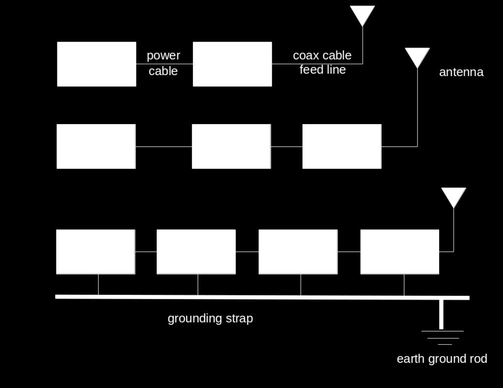
5 Station Block Diagrams
6 Basic Measuring Tools SWR / Watt Meter Antenna Analyzer Volt / Amp and Ohm Meter RF Loads, Reference and or Dummy Load Short pieces of Coax cables with quality connectors/adapters All measuring tools have an accuracy factor and a +/- 5% to 10% not uncommon for consumer grade tools. Commercial / Professional gear can still be 1%

7 Volt Meter / Amp Meter

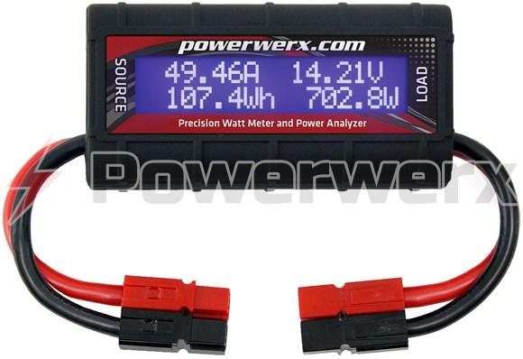
8 Watt Meter / SWR Meter Cross Needle meters fast measurements RF Power Forward vs. RF Power Reflected Wide range from QRP ranges to 2KW HF vs VHF/UHF

9 Antenna Analyzer Useful tool to measure SWR over range of frequencies Some have nice Plotting capabilities Portable so you can measure right at an antenna Can read Impedance in Ohms as well as SWR Utilizes low power RF signal so not used for Watt measurements! ie: Do not connect to your Tx!


10 RF Loads Precision 50 ohm loads With or Without Metering Can operate over very wide frequency range Dummy loads are very useful to test without an Antenna
11 Equipment Age Considerations Electronic Components age Performance of components can degrade over time Old Coax, weathered Coax cuts in coax, breaks, water intrusion Poor Connections tarnish / oxidization soldering or crimp quality Capacitors are big culprit Semi-conductors typically do not degrade, they Fail and stop working. Tubes however can degrade with age Solder or Crimp connections can break down due to stress, heat Be forewarned buying old gear, esp rigs 20+yrs or older Old gear is great, you just might need to upgrade components before putting it on the air Old Microphones, elements can impact your audio quality

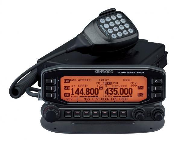
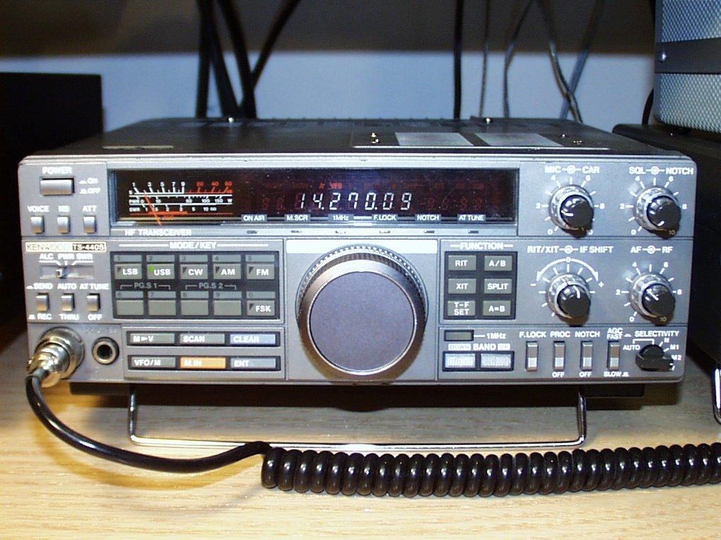
12 The Transmitter / Receiver


13 Power Supplies Linear vs. Switched Make sure capacity is greater than your load Use proper gauge wire Not all ports created equal Voltage/Current sagging can cause rig to cut out, reboot... or worse Make good connections; power poles for instance
14 Grounding Lightning protection Electrical Safety RF Ground Especially important for certain types of antenna ¼ λ Verticals, end fed long wires, unbalanced Helps eliminate common mode currents, RFI, noise from ground loops

15 Antennas Many Many Types Basic Forms Dipoles Verticals Loops Yagi Have Gain factor in db Generally larger and higher performs better
16 High Frequency - HF Height above ground for Dipoles varies w/ frequency; higher is better Dipole Element Lengths cut elements accurately Pattern and performance can be impacted by placement to nearby metal objects Low dipoles can help optimize signals within 600 mi. Verticals can lower the take off angle of RF on lower frequencies, 160m/80m for instance for greater distance


17 VHF/UHF Rubber Duck antenna, not very efficient Hand-held antenna pattern sensitive to placement Line of Sight comms. Polarization, Horiz vs. Vertical Mobile Antenna Placement can have big impact
18 Coaxial Cable Most common feed line Easy to use Not affected by nearby materials Has higher loss than open-wire line at most frequencies Air-insulated hard line has lowest loss Cheap versions of coax have braid that has been reduced to the point that any bend can cause a gap in the braid. This results in RF leaking and loss Technician License Course


19 Open-Wire Line Lighter and less expensive than coax Has lower loss than coax at most frequencies More difficult to use since it is affected by nearby materials Requires impedance matching equipment to use with most transceivers

20 Coaxial Transmission Lines

21 Coaxial Cable Loss Many types of Coax Not all created equal Impedance, 50 vs 75 vs xx That which works at HF may not work well at VHF/UHF Loss means less RF power makes it to the Antenna Loss is directly proportional to coax length. Minimize excessive lengths

22 Hard-line Coax For very long runs of coax Used at repeater sites and very large antenna installations Lower loss factor

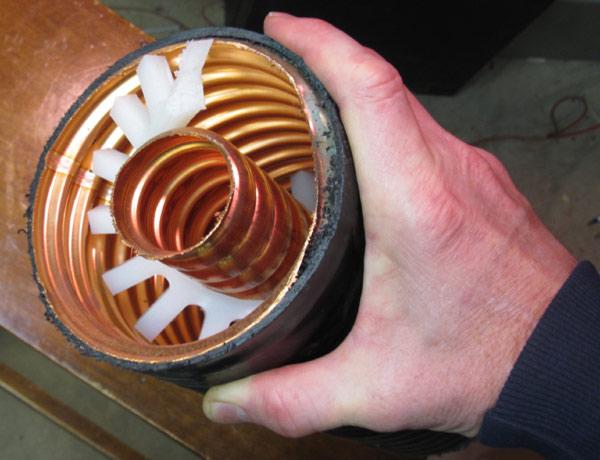
23 Low Loss Coax Yikes!

24 Double Shielded RG-214/U Reduces RF leakage Reduces Noise from getting into cable Less susceptible to shield braid opening up during bending of cable
25 Practical Feed Lines Coaxial cables Larger diameter cables have lower loss Loss is measured in db/foot Loss increases with frequency Keep water out! Protect the jacket from cuts and cracks and ultraviolet exposure. Some cable is UV-rated
26 The effect that feedline selection can make on station performance can be quickly appreciated by reviewing the chart below: It is important to note that the choice of feedline also has an impact on your station s receive performance. Without a preamp at the antenna, the line loss is the equivalent of adding an attenuator equal to the feedline loss in the receive path. Assume 100 watts input to 100 feet of the following coaxial cables; Pout (Power out in Watts) Pout@ Pout@ 50 MHz 144 MHz Pout@ 432 MHz Pout@ 902 MHz Pout@ 1296 MHz RG W 24 W 9W 2W <1 W RG W 53 W 30 W 16 W <1 W LMR W 71 W 54 W 41 W 31 W 1 5/8 in Hardline 97 W 94 W 89 W 83 W 81 W

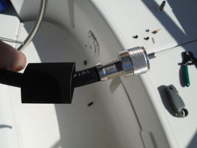
27 Coaxial Connectors UHF SO-239/PL-259 BNC N SMA F (cable TV)
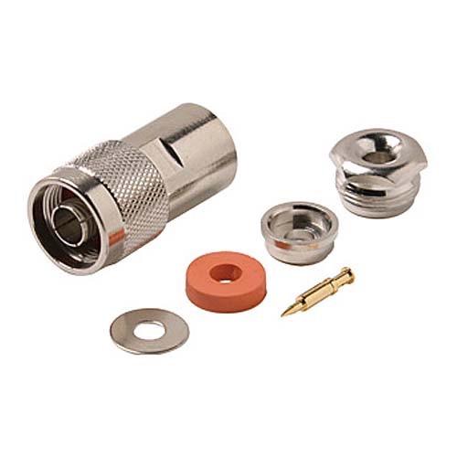
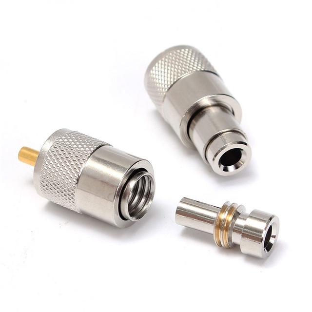
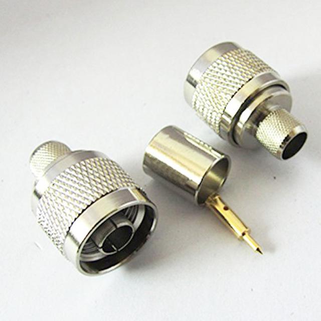
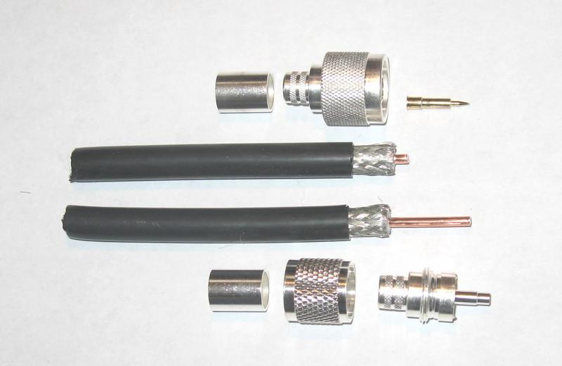
28 Connectors


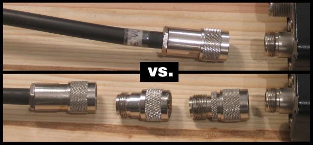
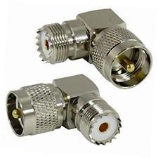
29 Adapters Minimize if possible
30 Installing Coaxial Connectors Soldering is the traditional way Use rosin-core solder and avoid cold solder joints See The Art of Soldering on the ARRL website Crimp connectors are becoming widely used by hams Obtain and learn to use proper crimping tools
31 Waterproofing Connectors MUST be waterproofed for use outdoors Type N are waterproof but still usually protected anyway Use good-quality electrical tape first, then a layer of self-vulcanizing tape, then another covering of electrical tape Air-core coaxial cable requires special connectors and techniques to waterproof
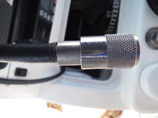
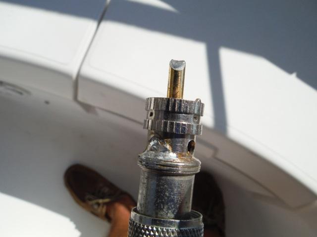
32 Connections - Trust but Verify


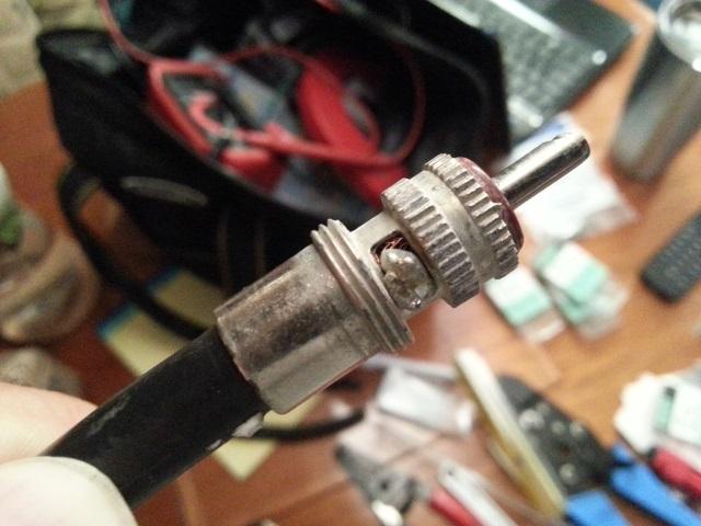
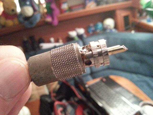
33 Too Much Heat!
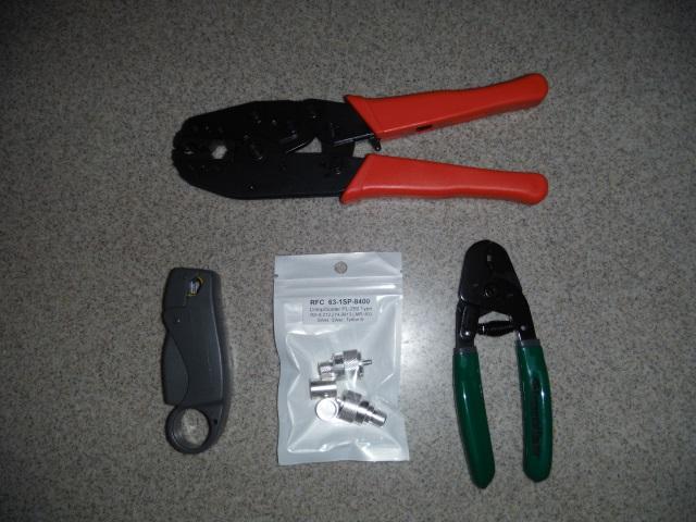
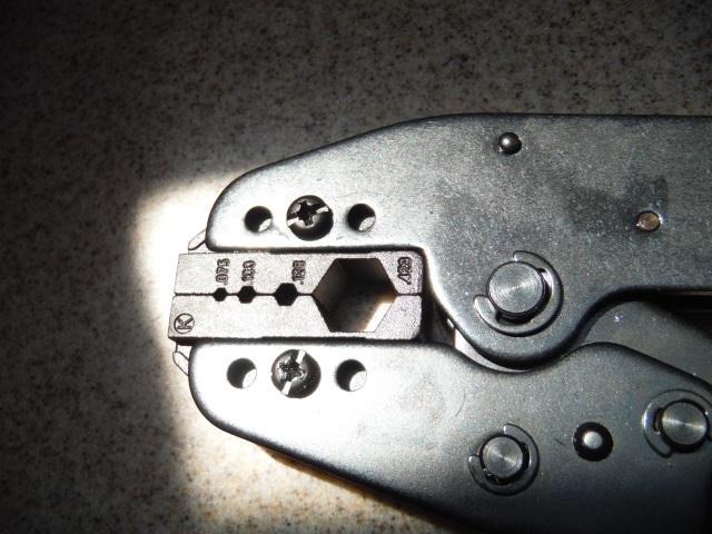
34 Crimped Connectors work If you use right tools
35 Measuring Techniques Measure individual components to avoid interaction and confusing results Transmit Power Tx into Watt Meter into Dummy Load Coax Feed-Line(s) Tx or Analyzer to Feedline and into Watt Meter/Load. Antenna Analyzer to measure SWR against frequencies plan on using Take Notes, record losses, add them up Measure with connectors and all cables you plan on using in your final configuration


36 Transmit RF Power Verify your rig is producing RF output it should Watt Meter to measure Eliminate Feed line and Antenna SWR Good time to validate power supply is not sagging during Tx
) * 100 With Analyzer, measuring SWR or coax loss in db Measure across multiple frequencies you intend to use Measure all interconnect")
37 Calculate Feed-Line Losses Measure w/o antenna, just RF Load and Coax Use your Transmitter or Antenna Analyzer With Tx, use Watt Meter; Loss % = (1 - (Pout / Pin)) * 100 With Analyzer, measuring SWR or coax loss in db Measure across multiple frequencies you intend to use Measure all interconnect cables

38 Antenna SWR Measurement Ideally want to measure at connector of antenna where feed line goes into If you measure with feed line, make sure its integer multiple half wavelength at frequency being measured. Velocity factor in Coax must be considered when calculating length of half wavelength.
39 Tx Power What s Acceptable? Minimize where you can Loss means less RF radiates at Antenna Also can generate Heat which is wasted energy High SWR, Loss, can damage your finals on some rigs. There will always some loss in your system. But with good antenna, you can also add some gain W VSWR % Reflected Wasted Watts At Antenna db Loss 1: : : : : : : : : : : : : : : : Err:502
40 Identify Areas of Possible Loss (1 or 2 db) Old Coaxial cable Coaxial lengths longer than required Poor coaxial connections (solder or crimping) Coaxial switches can lead to loss. Use only good switches Minor issues can add up to station db loss. Just take a step back and look at your station
41 What a difference a decibel can make! Many Hams will say Oh well, it s only a decibel (db) or 2 - or 3. That is not very significant so who cares! Well, true it is a very small number, but it amounts to one half (1/2) of the power to your station. Every db is important! You spend a lot of money to create power to your Station, so you don t want to lose it to leaks and loss.
42 New Ham: What s the difference between a 3element Yagi and a dipole antenna? Elmer: About 6 db. In the Technician License Course you learn two rules of thumb about decibels that get you through the exam and provide a rudimentary understanding of their use: 1)A doubling or halving of power equals a change of approximately 3 db. 2)A 10X change of power equals a change of 10 db. 3 db equates to about a 2:1 power ratio 10 db (aka 1 bel, or 1 10) equates to a 10:1 power ratio 20 db (aka 2 bel, or 1x10x10) equates to a 100:1 power ratio 30 db (aka 3 bel, or 1x10x10x10) equates to a 1000:1 power ratio and so on
43 How to calculate Decibels (db) A ratio expressed as an power of 10 to make large numbers easier to work with. db = 10 log (power ratio) db = 20 log (voltage ratio) Positive values in db indicate ratios > 1 and negative values of db are for ratios < 1. Antenna gain is discussed in terms of db Technician License Course
44 Loss in db is directly proportional to coaxial length. Be sure to cut the coax to the proper length. Don t leave excess coax just to save the coax for a later project. It will cost you in signal loss. Standing Wave Ratio (SWR) and coax line loss, i.e. mismatch load Since reflected power makes two (2) complete trips through the line (coax) each with attenuation it receives twice as much loss as that portion of the power that makes only 1 trip down the line.
45 Closing Thoughts If there is interest, we can setup demonstration perhaps in breakout session in future meeting: Connector installations Verifying your coax cables Many of topics touched on tonight can be greatly expanded upon; let club know what you want to see in future talks Elmer group does great job at getting your station up and running; as a New Ham you should gain knowledge to maintain / debug for peak performance.
46 UHF: Mt. Union, PL IRLP: 7100
Technician License. Course
 Technician License Course Technician License Course Chapter 4 Lesson Plan Module - 10 Practical Antennas The Dipole Most basic antenna The Dipole Most basic antenna The Dipole Total length is ½ wavelength
Technician Licensing Class T9
 Technician Licensing Class T9 Amateur Radio Course Monroe EMS Building Monroe, Utah January 11/18, 2014 January 22, 2014 Testing Session Valid dates: July 1, 2010 June 30, 2014 Amateur Radio Technician
4/25/2012. Supplement T9. 2 Exam Questions, 2 Groups. Amateur Radio Technician Class T9A: T9A: T9A: T9A:
 Amateur Radio Technician Class Element 2 Course Presentation ti ELEMENT 2 SUB-ELEMENTS Technician Licensing Class Supplement T9 Antennas, Feedlines 2 Exam Questions, 2 Groups T1 - FCC Rules, descriptions
Technician Licensing Class. Antennas
 Technician Licensing Class Antennas Antennas A simple dipole mounted so the conductor is parallel to the Earth's surface is a horizontally polarized antenna. T9A3 Polarization is referenced to the Earth
Technician License Course Chapter 4. Lesson Plan Module 10 Practical Antennas
 Technician License Course Chapter 4 Lesson Plan Module 10 Practical Antennas The Dipole Most basic antenna Total length is ½ wavelength (½ λ) Usual construction: Two equal halves of wire, rod, or tubing
Milton Keynes Amateur Radio Society (MKARS)
") Milton Keynes Amateur Radio Society (MKARS) Intermediate Licence Course Feeders Antennas Matching (Worksheets 31, 32 & 33) MKARS Intermediate Licence Course - Worksheet 31 32 33 Antennas Feeders Matching
Milton Keynes Amateur Radio Society (MKARS) Intermediate Licence Course Feeders Antennas Matching (Worksheets 31, 32 & 33) MKARS Intermediate Licence Course - Worksheet 31 32 33 Antennas Feeders Matching
Least understood topics by most HAMs RF Safety Ground Antennas Matching & Feed Lines
 Least understood topics by most HAMs RF Safety Ground Antennas Matching & Feed Lines Remember this question from the General License Exam? G0A03 (D) How can you determine that your station complies with
Welcome to Ham Radio 201 New General / Extra Session
 Welcome to Ham Radio 201 New General / Extra Session Sponsored by Agenda New Technician / New Licensee 8:00 Kickoff 8:15 VHF/UHF Gear - George 9:00 VHF/UHF Operating - Beric 9:45 VHF Digital Voice George
Technician License. Course
 Technician License Course Technician License Course Chapter 4 Lesson Plan Module - 9 Antenna Fundamentals Feed Lines & SWR The Antenna System The Antenna System Antenna: Transforms current into radio waves
Technician License Course Chapter 4. Lesson Plan Module 9 Antenna Fundamentals, Feed Lines & SWR
 Technician License Course Chapter 4 Lesson Plan Module 9 Antenna Fundamentals, Feed Lines & SWR The Antenna System Antenna: Transforms current into radio waves (transmit) and vice versa (receive). Feed
Technician Licensing Class. Lesson 4. presented by the Arlington Radio Public Service Club Arlington County, Virginia
 Technician Licensing Class Lesson 4 presented by the Arlington Radio Public Service Club Arlington County, Virginia 1 Quiz Sub elements T6 & T7 2 Good Engineering Practice Sub element T8 3 A Basic Station
Antennas and Propagation Chapters T4, G7, G8 Antenna Fundamentals, More Antenna Types, Feed lines and Measurements, Propagation
 Antennas and Propagation Chapters T4, G7, G8 Antenna Fundamentals, More Antenna Types, Feed lines and Measurements, Propagation =============================================================== Antenna Fundamentals
db = 10 log10 (P1/P2) where P1 and P2 are two power levels
 where P1 and P2 are two power levels") A Quick Introduction to Decibels (db) Unit is the Bel: named after A.G. Bell who devised it for his work with deafness and audio sound levels. Now used for all frequencies of AC power. Decibel (db): -1
A Quick Introduction to Decibels (db) Unit is the Bel: named after A.G. Bell who devised it for his work with deafness and audio sound levels. Now used for all frequencies of AC power. Decibel (db): -1
FCC Technician License Course
 FCC Technician License Course 2014-2018 FCC Element 2 Technician Class Question Pool Presented by: Tamiami Amateur Radio Club (TARC) WELCOME To the third of 4, 3-hour classes presented by TARC to prepare
4 Antennas as an essential part of any radio station
 4 Antennas as an essential part of any radio station 4.1 Choosing an antenna Communicators quickly learn two antenna truths: Any antenna is better than no antenna. Time, effort and money invested in the
Intermediate Course (5) Antennas and Feeders
 Antennas and Feeders") Intermediate Course (5) Antennas and Feeders 1 System Transmitter 50 Ohms Output Standing Wave Ratio Meter Antenna Matching Unit Feeder Antenna Receiver 2 Feeders Feeder types: Coaxial, Twin Conductors
Intermediate Course (5) Antennas and Feeders 1 System Transmitter 50 Ohms Output Standing Wave Ratio Meter Antenna Matching Unit Feeder Antenna Receiver 2 Feeders Feeder types: Coaxial, Twin Conductors
TWO METER HOMEMADE SLIM JIM ANTENNA
 Gordon Gibby July 15, 2016 TWO METER HOMEMADE SLIM JIM ANTENNA WIRE: Start with a piece of solid #14 AWG household wire approximately 3 yards and 9 inches long (117 ) (It is easier to be a couple inches
COAXIAL TRANSMISSION LINE COMMON-MODE CURRENT
 COAXIAL TRANSMISSION LINE COMMON-MODE CURRENT Introduction Coaxial transmission lines are popular for their wide frequency bandwidth and high resistance to electromagnetic interference (EMI). Coax cables
Antenna Design for FM-02
 Antenna Design for FM-02 I recently received my FM-02 FM transmitter which I purchased from WLC. I researched the forum on what antennas where being used by the DIY community and found a nice write-up
General License Class Chapter 6 - Antennas. Bob KA9BHD Eric K9VIC
 General License Class Chapter 6 - Antennas Bob KA9BHD Eric K9VIC Learning Objectives Teach you enough to get all the antenna questions right during the VE Session Learn a few things from you about antennas
Chapter 6 Antenna Basics. Dipoles, Ground-planes, and Wires Directional Antennas Feed Lines
 Chapter 6 Antenna Basics Dipoles, Ground-planes, and Wires Directional Antennas Feed Lines Some General Rules Bigger is better. (Most of the time) Higher is better. (Most of the time) Lower SWR is better.
Technician License Course Chapter 4
 Technician License Course Chapter 4 Propagation, Basic Antennas, Feed lines & SWR K0NK 26 Jan 18 The Antenna System Antenna: Facilitates the sending of your signal to some distant station. Feed line: Connects
SWR myths and mysteries.
 SWR myths and mysteries. By Andrew Barron ZL3DW September 2012 This article will explain some of the often misunderstood facts about antenna SWR at HF and uncover some popular misconceptions. The questions
4/29/2012. General Class Element 3 Course Presentation. Ant Antennas as. Subelement G9. 4 Exam Questions, 4 Groups
 General Class Element 3 Course Presentation ti ELEMENT 3 SUB ELEMENTS General Licensing Class Subelement G9 Antennas and Feedlines 4 Exam Questions, 4 Groups G1 Commission s Rules G2 Operating Procedures
L. B. Cebik, W4RNL. Basic Transmission Line Properties
 L. B. Cebik, W4RNL In the course of developing this collection of notes, I have had occasion to use and to refer to both series and parallel coaxial cable assemblies. Perhaps a few notes specifically devoted
The J-Pole Antenna. Gary Wescom
 The J-Pole Antenna Gary Wescom - 2018 Much has been written about the J-Pole antenna. A simple Google search will net days worth of reading material on the subject. That would tend to indicate this paper
Improved Ionospheric Propagation With Polarization Diversity, Using A Dual Feedpoint Cubical Quad Loop
 Improved Ionospheric Propagation With Polarization Diversity, Using A Dual Feedpoint Cubical Quad Loop by George Pritchard - AB2KC ab2kc@optonline.net Introduction This Quad antenna project covers a practical
The Principle V(SWR) The Result. Mirror, Mirror, Darkly, Darkly
 The Result. Mirror, Mirror, Darkly, Darkly") The Principle V(SWR) The Result Mirror, Mirror, Darkly, Darkly 1 Question time!! What do you think VSWR (SWR) mean to you? What does one mean by a transmission line? Coaxial line Waveguide Water pipe Tunnel
The Principle V(SWR) The Result Mirror, Mirror, Darkly, Darkly 1 Question time!! What do you think VSWR (SWR) mean to you? What does one mean by a transmission line? Coaxial line Waveguide Water pipe Tunnel
SOME USES FOR RF1,RF5 and VA1 ANALYSTS. SWR Measurement
 SOME USES FOR RF1,RF5 and VA1 ANALYSTS THE HANDIEST INSTRUMENTS IN DECADES! When you put up an antenna in the the old days, it could be a real struggle. The only way to tell if it was tuned to the right
The Amazing MFJ 269 Author Jack Tiley AD7FO
 The Amazing MFJ 269 Author Jack Tiley AD7FO ARRL Certified Emcomm and license class Instructor, Volunteer Examiner, EWA Technical Coordinator and President of the Inland Empire VHF Club What Can be Measured?
Antennas Demystified Antennas in Emergency Communications. Scott Honaker N7SS
 Antennas Demystified Antennas in Emergency Communications Scott Honaker N7SS Importance of Antennas Antennas are more important than the radio A $5000 TV with rabbit ears will have a lousy picture Antennas
An Introduction to Radio Frequency Interference
 An Introduction to Radio Frequency Interference Ron Hranac, N0IVN Member, ARRL EMC Committee ARRL Colorado Section Technical Specialist What is RFI? RFI is an abbreviation for radio frequency interference
Amateur Extra Manual Chapter 9.4 Transmission Lines
 9.4 TRANSMISSION LINES (page 9-31) WAVELENGTH IN A FEED LINE (page 9-31) VELOCITY OF PROPAGATION (page 9-32) Speed of Wave in a Transmission Line VF = Velocity Factor = Speed of Light in a Vacuum Question
Practical Antennas and. Tuesday, March 4, 14
 Practical Antennas and Transmission Lines Goals Antennas are the interface between guided waves (from a cable) and unguided waves (in space). To understand the various properties of antennas, so as to
The DBJ-1: A VHF-UHF Dual-Band J-Pole
 By Edison Fong, WB6IQN The DBJ-1: A VHF-UHF Dual-Band J-Pole Searching for an inexpensive, high-performance dual-band base antenna for VHF and UHF? Build a simple antenna that uses a single feed line for
Back to the Basics Setting up a VHF/UHF Station
 Back to the Basics Setting up a VHF/UHF Station Back to The Basics Your First VHF/UHF Station Topics that will be covered: Radios l Base/mobile vs. Hand Held l Pluses and minuses of each l Antennas l Vertical
MFJ Balanced Line Tuner
 MFJ Balanced Line Tuner Introduction The MFJ-974H balanced line antenna tuner is a fully balanced true balanced line antenna tuner, providing superb current balance throughout a very wide matching range
Colubris Networks. Antenna Guide
 Colubris Networks Antenna Guide Creation Date: February 10, 2006 Revision: 1.0 Table of Contents 1. INTRODUCTION... 3 2. ANTENNA TYPES... 3 2.1. OMNI-DIRECTIONAL ANTENNA... 3 2.2. DIRECTIONAL ANTENNA...
Portable Magnetic Loop Antenna. KG5EAO Rick Bono
 Portable Magnetic Loop Antenna KG5EAO Rick Bono April 2, 2016 Overview Develop a Portable magnetic loop antenna for use on HF bands running QRP. Portable and easy to deploy Ideally run on the 40m through
Observations Regarding Selection and Installation of Masthead VHF whip antennas:
 VHF AIS masthead antenna and coax installation, selection, and test. Stan Honey and Dan Jowett 28 August 2018 Observations Regarding Selection and Installation of Masthead VHF whip antennas: Whip Antennas
Transmission lines. Characteristics Applications Connectors
 Transmission lines Characteristics Applications Connectors Transmission Lines Connect They allow us to conduct RF Signals between our station components, they connect: Transceivers Antennas Tuners Amplifiers
Ameritron RCS-10 INTRODUCTION
 Ameritron RCS-10 INTRODUCTION The RCS-10 is a versatile antenna switch designed for 50-ohm systems. It handles high power, and sealed relays offer excellent life and connection reliability. It requires
How to use your antenna tuner.
 How to use your antenna tuner. There's more to it than what is in your manual or on most how to do it websites! http://www.arrl.org/tis/info/ant-tuner-op.html Here is a neat site with a "T" network simulator.
Amateur Radio License. Propagation and Antennas
 Amateur Radio License Propagation and Antennas Todays Topics Propagation Antennas Propagation Modes Ground wave Low HF and below, ground acts as waveguide Line-of-Sight (LOS) VHF and above, radio waves
Range Considerations for RF Networks
 TI Technology Days 2010 Range Considerations for RF Networks Richard Wallace Abstract The antenna can be one of the most daunting components of wireless designs. Most information available relates to large
Portable or Emergency VHF Antennas Paul R. Jorgenson KE7HR
 For emergency or public service events it is often necessary to have more antenna than the rubber duck on your handheld VHF radio. Nearly ANY external antenna will provide more coverage for your handheld
The first thing to realize is that there are two types of baluns: Current Baluns and Voltage Baluns.
 Choosing the Correct Balun By Tom, W8JI General Info on Baluns Balun is an acronym for BALanced to UNbalanced, which describes certain circuit behavior in a transmission line, source or load. Most communications
Lesson 11: Antennas. Copyright Winters Version 1.0. Preparation for Amateur Radio Technician Class Exam
 Lesson 11: Antennas Preparation for Amateur Radio Technician Class Exam Topics Antenna ½ wave Dipole antenna ¼ wave Vertical antenna Antenna polarization Antenna location Beam antennas Test Equipment Exam
1) Transmission Line Transformer a. First appeared on the scene in 1944 in a paper by George Guanella as a transmission line transformer, the 1:1
 Transmission Line Transformer a. First appeared on the scene in 1944 in a paper by George Guanella as a transmission line transformer, the 1:1") 1) Transmission Line Transformer a. First appeared on the scene in 1944 in a paper by George Guanella as a transmission line transformer, the 1:1 Guanella Balun is the basic building Balun building block.
1) Transmission Line Transformer a. First appeared on the scene in 1944 in a paper by George Guanella as a transmission line transformer, the 1:1 Guanella Balun is the basic building Balun building block.
MFJ-219/219N 440 MHz UHF SWR Analyzer TABLE OF CONTENTS
 MFJ-219/219N 440 MHz UHF SWR Analyzer TABLE OF CONTENTS Introduction...2 Powering The MFJ-219/219N...3 Battery Installation...3 Operation Of The MFJ-219/219N...4 SWR and the MFJ-219/219N...4 Measuring
ANTENNAS. I will mostly be talking about transmission. Keep in mind though, whatever is said about transmission is true of reception.
 Reading 37 Ron Bertrand VK2DQ http://www.radioelectronicschool.com ANTENNAS The purpose of an antenna is to receive and/or transmit electromagnetic radiation. When the antenna is not connected directly
Antenna Systems for the Recently Licensed Ham --3 Talks-- BVARC Meeting May 10 th, 2012
 Antenna Systems for the Recently Licensed Ham --3 Talks-- BVARC Meeting May 10 th, 2012 Understanding the Cardinal Rules of the Ham Radio Antenna System Rick Hiller -- W5RH Utilizing Your New Found Practical
MFJ-208 VHF SWR Analyzer
 MFJ-208 VHF SWR Analyzer Thank you for purchasing the MFJ-208 VHF SWR Analyzer. The MFJ-208 gives you a direct readout of your antenna's SWR without the need for formulas or indirect readings. The MFJ-
Newcomers And Elmers Net: Wire Antennas Robert AK3Q
 Newcomers And Elmers Net: Wire Antennas 02-07-16 Robert AK3Q Wire antennas represent one of the greatest values in the radio hobby world. For less than the cost of a good meal out on the town you can buy
Introduction. Understanding Power Ratings. Peak Reading SWR/Wattmeter
 Introduction The MFJ-962D is a "T" network roller inductor tuner with built-in antenna switching, RF power and SWR metering and a 1:1 balun. The largest amplifiers that can safely be used include the Heathkit
Chapter 4. Propagation, Antennas and Feed Lines. Propagation Black magic topic #1. How do radio waves get from point A to point B?
 Chapter 4 Propagation, Antennas and Feed Lines Propagation Black magic topic #1. How do radio waves get from point A to point B? 1 Radio Wave Propagation Normally radio waves travel in a straight line,
A Tri Band Antenna for 2 meters, 220 MHz, and 70cm Antenna Without Radials. By: Edison Fong (WB6IQN)
") A Tri Band Antenna for 2 meters, 220 MHz, and 70cm Antenna Without Radials By: Edison Fong (WB6IQN) Twenty years ago a single band handie talkie would have been adequate for emergency use since almost
A Tri Band Antenna for 2 meters, 220 MHz, and 70cm Antenna Without Radials By: Edison Fong (WB6IQN) Twenty years ago a single band handie talkie would have been adequate for emergency use since almost
1997 MFJ ENTERPRISES, INC.
 INSTRUCTION MANUAL CAUTION: Read All Instructions Before Operating Equipment MFJ ENTERPRISES, INC. 300 Industrial Park Road Starkville, MS 39759 USA Tel: 601-323-5869 Fax: 601-323-6551 VERSION 6C COPYRIGHT
Emergency Antennas. Presented by Ham Hilliard W4GMM
 Emergency Antennas Presented by Ham Hilliard W4GMM Dipole antenna Vertical antenna Random wire antenna Dipole antenna The half wave dipole antenna consists of a conductive wire or rod that is half the
VHF/UHF Dual Band J-Pole. By: Ed Fong WB6IQN
 VHF/UHF Dual Band J-Pole By: Ed Fong WB6IQN email: edison_fong@hotmail.com ARRL VHF/UHF Antenna Classics ARRL Vol. 8 Antenna Compendium ARRL Vol. 3 Antenna Compendium QST March 2007 QST February 2003 QST
Jacques Audet VE2AZX. Nov VE2AZX 1
 Jacques Audet VE2AZX VE2AZX@amsat.org Nov. 2006 VE2AZX 1 - REASONS FOR USING A BALUN - TYPES OF BALUNS - CHECK YOUR BALUN WITH AN SWR ANALYZER - MEASURING THE IMPEDANCE OF A NUMBER OF FERRITES - IMPEDANCE
87.5 TO MHz BAND II 2 WAY 4.8dBi STACKED DIPOLE ANTENNA
 87.5 TO 108.0 MHz BAND II 2 WAY 4.8dBi STACKED DIPOLE ANTENNA 1. INTRODUCTION 3 1.1. GENERAL INFORMATION 3 1.2. UNPACKING AND CHECKING 3 1.3. WARRANTY 3 1.4. USER SAFETY RESPONSIBILITY 4 1.5. INSTALLATION
Plotting all this data got old using a chart to look up VSWR each time. Here is a formula I found rooting around the web. Let Excel do the work
 My compliments to John, K5GD for heading up the antenna building sessions, and thanks to Ron, N5QV for providing the antenna comparison data. I wanted to share my experience with this project. First of
Exploring the HF Bands
 Exploring the HF Bands By Frank Tomkins, W8EZT Cuyahoga Falls Amateur Radio Club What You Need to Get There, What To Do Once You Are There, and Some Useful Operating Tips 1 The HF Bands As Technicians
Cray Valley Radio Society. Real Life Wire Antennas
 Cray Valley Radio Society Real Life Wire Antennas 1 The basic dipole The size of an antenna is determined by the wavelength of operation In free space: ~3x10 8 m/s Frequency x Wavelength = Speed of Light,
MFJ-249B HF/VHF SWR ANALYZER
 TABLE OF CONTENTS MFJ-249B... 2 Introduction... 2 Powering The MFJ-249B... 3 Battery Installation... 3 Alkaline Batteries... 3 NiCd Batteries... 4 Power Saving Mode... 4 Operation Of The MFJ-249B...5 SWR
A TRANSMISSION LINE BALANCE TEST METER
 by Lloyd Butler VK5BR with modifications by Phil Storr VK5SRP. Here is a simple meter to check the balance of currents running in the two legs of a transmission line. It can be used to check the balance
MFJ-835 RF Ammeter. Introduction. Uses
 MFJ-835 RF Ammeter Introduction Congratulations on purchasing the MFJ-835 Balanced Line RF Ammeter. The MFJ-835 is designed for measuring balanced RF feedline current on 1.8-30 MHz while having low interaction
MFJ-949E. tuner antenowy skrzynka antenowa. Instrukcja obsługi. importer:
 Instrukcja obsługi MFJ-949E tuner antenowy skrzynka antenowa importer: PRO-FIT Centrum Radiokomunikacji InRadio ul. Puszkina 80 92-516 Łódź tel: 42 649 28 28 e-mail: biuro@inradio.pl www.inradio.pl MFJ-949E
Users Manual. 200W HF/50MHz Band Auto Antenna Tuner. Model HC-200AT
 Users Manual 200W HF/50MHz Band Auto Antenna Tuner Model HC-200AT Caution 1. Never remove or open the tuner cover while transmitting. When there is RF in the circuits of the tuner, there will be high voltage
Feed Line Currents for Neophytes.
 Feed Line Currents for Neophytes. This paper discusses the sources of feed line currents and the methods used to control them. During the course of this paper two sources of feed line currents are discussed:
Using High Performance Multiplexer Technology to Improve Your HF Station Capability. by Andrei Fedorishchev RA6LBS
 Using High Performance Multiplexer Technology to Improve Your HF Station Capability by Andrei Fedorishchev RA6LBS Agenda A bit of history What is a multiplexer? Can I fry my radios? Specifications of multiplexers
MFJ-941E Versa Tuner II GENERAL INFORMATION:
 GENERAL INFORMATION: MFJ VERSA TUNER II The MFJ-941E is designed to match virtually any transmitter to any antenna, including dipoles, inverted-vees, verticals, mobile whips, beams, random wires, and others
Chapter 12: Transmission Lines. EET-223: RF Communication Circuits Walter Lara
 Chapter 12: Transmission Lines EET-223: RF Communication Circuits Walter Lara Introduction A transmission line can be defined as the conductive connections between system elements that carry signal power.
MIRAGE BD-35 DUAL BAND POWER AMPLIFIER
 MIRAGE BD-35 DUAL BAND POWER AMPLIFIER INTRODUCTION: The Mirage BD-35 is a 45/35 watt dual band power amplifier for use with today's dual band handie talkies operating in the 144/440MHz bands. We have
MFJ-969 Versa Tuner II Instruction Manual
 MFJ-969 Versa Tuner II Instruction Manual General Information The MFJ-969 is a 300 watt RF output power antenna tuner that will match any transmitter or transceiver to virtually any antenna. Peak or average
A short, off-center fed dipole for 40 m and 20 m by Daniel Marks, KW4TI
 A short, off-center fed dipole for 40 m and 20 m by Daniel Marks, KW4TI Version 2017-Nov-7 Abstract: This antenna is a 20 to 25 foot long (6.0 m to 7.6 m) off-center fed dipole antenna for the 20 m and
MFJ-834 RF Ammeter. Introduction. Uses
 MFJ-834 RF Ammeter Introduction Congratulations on purchasing the MFJ-834 RF Ammeter. The MFJ-834 is designed for measuring in-line RF feedline current on 1.8-30 MHz while having low interaction on the
Tuning a 160M full sized vertical with strong AM broadcast RF present on the antenna. Jay Terleski, WX0B
 Tuning a 160M full sized vertical with strong AM broadcast RF present on the antenna. Jay Terleski, WX0B I often get asked about how to match a ¼ WL vertical to a 50 ohm transmission line and what to do
Lesson 9: Base Stations
 Lesson 9: Base Stations Preparation for Amateur Radio Technician Class Exam Topics Home Stations Basic Station Layout RTTY and Data Communications Station Accessories Wavelengths Feed Lines Impedance-matching
ALWAYS ATTACH THE SAFETY ROPE TO A STABLE SUPPORT BEFORE ATTEMPTING TO ATTACH THE UNIVERSAL MOUNT TO A WINDOW FRAME OR RAIL.
 MFJ-1623 Introduction The MFJ-1623 was designed to provide portable or permanent HF communications on 30 through 10 meters and VHF on 6 meters. The universal mount design allows the user to install the
Array Solutions Four Square Array Manual and User s Guide
 Array Solutions Four Square Array Manual and User s Guide Array Solutions Four Square Array Pattern Steering System Congratulations! You have selected one of the finest phased array steering systems made.
FM BROADCASTING BAND II 4 WAY dbi STACKED CIRCULAR ANTENNA
 FM BROADCASTING BAND II 4 WAY + 5.8 dbi STACKED CIRCULAR ANTENNA Please read this manual carefully. To avoid harmful interference to other users of the electromagnetic spectrum, do not power up the antenna
Computer Networks Lecture -4- Transmission Media. Dr. Methaq Talib
 Computer Networks Lecture -4- Transmission Media Dr. Methaq Talib Transmission Media A transmission medium can be broadly defined as anything that can carry information from a source to a destination.
EVERY rotor control, remote antenna selector also has a common mode choke at each end of the cable!
 Radio Communication Choosing a Coax Feed Line Choke By Bob Brehm, AK6R RFI Tip Sheet #RC-1 How to choose feed line chokes, line isolators, baluns, or ununs for coax fed dipoles, verticals, hex beams, slopers,
VSWR Page 1 of 7. The Effects of VSWR on Transmitted Power. P =(Z1-Z o. +Z o )/(Z 1. are complex numbers so "p" is also a complex number.
/(Z 1. are complex numbers so p is also a complex number.") VSWR Page 1 of 7 The Effects of VSWR on Transmitted Power By James G. Lee, W6VAT No matter how long you have been a ham, sooner of later you will be involved in at least one discussion of something called
VSWR Page 1 of 7 The Effects of VSWR on Transmitted Power By James G. Lee, W6VAT No matter how long you have been a ham, sooner of later you will be involved in at least one discussion of something called
WRAPS Rotor Enhancements Add a Second Beam and Circular Polarization
 WRAPS Rotor Enhancements Add a Second Beam and Circular Polarization Mark Spencer, WA8SME (mspencer@arrl.org) ARRL Education and Technology Program Part 1: Tricked-Out WRAPS Satellite Antenna Rotator Adds
Basic Wire Antennas. Part II: Loops and Verticals
 Basic Wire Antennas Part II: Loops and Verticals A loop antenna is composed of a single loop of wire, greater than a half wavelength long. The loop does not have to be any particular shape. RF power can
Nick Garner N3WG and George Zafiropoulos KJ6VU
 Nick Garner N3WG and George Zafiropoulos KJ6VU Introduction Over the last few years, there has been a significant increase in the number of radio amateurs interested in portable operating. This is due
INTERNATIONAL ELECTRICAL WIRE & CABLE, INC.
 Catalog #204 INTERNATIONAL ELECTRICAL WIRE & CABLE, INC. Marine Cable Products Made in the U.S.A. Phone: 800-323-0210 Fax: 630-860-0305 E-Mail: KevinM@wiresales.net Website: wiresales.net TRUTHS AND MYTHS
VHF and UHF Antennas for QRP Portable Operation. Prepared for the QRP forum at Pacificon2011 by KK6MC James Duffey October 15, 2011
 VHF and UHF Antennas for QRP Portable Operation Prepared for the QRP forum at Pacificon2011 by KK6MC James Duffey October 15, 2011 Overview Get on the air from portable locations with simple and effective
SCARS Technician / General License Course Week 4
 SCARS Technician / General License Course Week 4 Radio Wave Propagation: Getting from Point A to Point B Radio waves propagatein many ways depending on Frequency of the wave Characteristics of the environment
VHF/UHF Beyond FM Bob Witte KØNR Page 1
 VHF/UHF Beyond FM Technical Coordinator Colorado Section Page 1 Objective The objective of this presentation is to provide an introduction to operating on VHF/UHF, going beyond the usual FM / Repeater
A Folding 5-Element Yagi for 144 MHz
 A Folding 5-Element Yagi for 144 MHz Steve Kavanagh, VE3SMA, April 2017 1. Introduction I have found antennas which fold up quickly to take less space in the car to be useful in VHF/UHF portable operating.
MAGNETIC LOOP SYSTEMS SIMPLIFIED
 MAGNETIC LOOP SYSTEMS SIMPLIFIED By Lez Morrison VK2SON Many articles have been published and made available on websites recently. Unfortunately they have tended to make construction sound complicated
August, Antennas 101: A Course in RF Basics
 August, 2012 Antennas 101: A Course in RF Basics Antenna Basics Agenda: In today s training, we will go over a brief summary of the following topics at a basic level: Electromagnetic Waves Frequency and
ANTENNAS Wires, Verticals and Arrays
 ANTENNAS Wires, Verticals and Arrays Presented by Pete Rimmel N8PR 2 1 Tonight we are going to talk about antennas. Anything that will conduct electricity can be made to radiate RF can be called an antenna.
CHAPTER 8 ANTENNAS 1
 CHAPTER 8 ANTENNAS 1 2 Antennas A good antenna works A bad antenna is a waste of time & money Antenna systems can be very inexpensive and simple They can also be very expensive 3 Antenna Considerations
High-Power Directional Couplers with Excellent Performance That You Can Build
 High-Power Directional Couplers with Excellent Performance That You Can Build Paul Wade W1GHZ 2010 w1ghz@arrl.net A directional coupler is used to sample the RF energy travelling in a transmission line
Device Interconnection
 Device Interconnection An important, if less than glamorous, aspect of audio signal handling is the connection of one device to another. Of course, a primary concern is the matching of signal levels and