VHF and UHF Antennas for QRP Portable Operation. Prepared for the QRP forum at Pacificon2011 by KK6MC James Duffey October 15, 2011
|
|
|
- Marian Knight
- 6 years ago
- Views:
Transcription
1 VHF and UHF Antennas for QRP Portable Operation Prepared for the QRP forum at Pacificon2011 by KK6MC James Duffey October 15, 2011
2 Overview Get on the air from portable locations with simple and effective homebrew antennas Aimed at FT-817 style portable operator, but applicable to anyone Antennas easily assembled and disassembled for transport No special tools required Supports QRP Portable class in ARRL contests and Hilltopper category in CQ contest Versatile designs can be adapted to materials at hand Easy to build
3 Broadband designs Overall Design Drivers Minimize detuning with weather/proximity effects Eliminates precision assembly some slop is OK Makes in-field repairs/modifications easier Front-to-back ratio & sidelobes are secondary considerations Same, manageable boom length on all bands Gives roughly equal signal strength on all bands at the same distance big help in QSYing with same station Easy to carry Gain increases with increasing frequency Path loss increases with increasing frequency Assembly and disassembly without tools Wing nuts Friction fit
4 Moxon Good Candidate for Portable Operations 2 element Yagi with optimum spacing 50 Ohm feedpoint 4.1 db gain over dipole High front to side, front-to-back ratio Broadband Dimensions not critical for good gain & 50 Ohm impedance Going from loop to Moxon yields big difference in performance
5 WA5VJB Easy Yagis Easy antennas to build and get operating Readily available parts hardware store and Radio Shack Little or no tuning required if reasonable care is used in cutting elements Good for single band use Proven design < > Easily modified for disassembly/assembly to use portable Lay driven element over horizontally and place on top of boom Skews pattern slightly, but gain remains the same
6 Partitioning Antennas FT 817 and similar rigs have 2 antenna connectors; set up as 6M on one and 144/432 on the other Makes sense to have two antennas, one on 6M and one for 432/144 MHz Moxon on 6M, DK7ZB on 432/144 MHz With single band rigs, or rigs with antenna connectors for each band, single band antennas make more sense
7 Building Yagis Cut and measured to achievable tolerances, good Yagis will perform as designed 1/16 easy; 1/32 or 1mm possible with care Band Tolerance 6m +/- 1.7 cm +/- 5/8 inch 2m +/- 0.5 cm +/- 3/16 70 cm +/- 0.2 cm +/- 1/16 Tolerance should be less than 1 degree of phase shift for minimum effect, but really should be as low as you can easily achieve +/- wavelength/360

8 It is better to cut too short rather than too long Yagis have low pass response Cutting long will push the frequency response down
9 Rapid assembly and disassembly of portable Yagis Color code elements and boom location Colored electrical tape Place stop on one side of element Tape, retaining ring, or solder blob Use toggle/cordlock on the other side to keep in place Velcro straps hold elements to boom when transporting, or use PVC and store inside
10 Moxon Geometry A B 50 Ω Feed point Maximum Radiation C D Compact, easy to feed gain antenna Initial design by Moxon G6XN, design formalized and popularized by W4RNL Two element Yagi in which driven element/reflector current and spacing can be independently set Design calculators available on net see < > for example Insulated wire requires some cut and try
11 Easy Moxon Bracket 40 degrees, 140 degrees not typical angles in miter box Start with bracket material I used wood, same relative dimensions as Moxon 2. Draw diagonals, 1 and 2 3. These will be where spreaders go 4. Dimensions for center bracket from 2 x 4 with A= 76.5 and B+C+D = 27
12 K8DU Design for Collapsible Moxon Collapsible design < > Elements and spreaders under stress (tension) spreaders free to rotate so antenna is self aligning to correct angles Wire elements must be assembled accurately But only once Easy to fabricate with hand tools from commonly available materials Easy to assemble in field For rigid alternate made of Al angle < >
13 Moxon Performance SWR Frequency (MHz) High front to back ratio and deep side lobes require close attention to end-to-end spacing Gain, SWR, bandwidth do not This is OK, particularly for portable operations
14 Simple Solution For 144/432 - Use 144 MHz Yagi on 432 MHz Pattern split and SWR maybe above 2:1, but works
15 DK7ZB Closely Coupled Resonator Dual Band Antennas Single feed line for two bands Two dipoles act as coupled resonators 144 MHz dipole Feed point for 144 MHz & 432 MHz 432 MHz driven element 144 MHz impedance depends on length 432 MHz impedance depends on length and spacing
16 DK7ZB 144MHz/432MHz Yagi - English El Len Pos Dia Material Brass Brass Brass Brass Brass Brass Brass Brass Brass Dimensions in inches, with position measured from the first element 0.16 inch driven element from 6 gauge Cu wire - use 1/8 inch and SWR on 432 will be a bit high Modeled with YagiCAD6 6.1 Copyright Paul McMahon VK3DIP
17 ) DK7ZB 144MHz/432MHz Dual Band Metric All elements made with 3,2mm welding rods, except the radiator (4mm) El.-Nr. Element Length Position 1 Reflector for 2m 1022 mm 0 mm 2 Reflector for 70cm 329 mm 110mm 3 Radiator 2m and 70cm 977 mm (4mm) 260 mm 4 Director 1 für 70cm 322 mm 300 mm 5 Director 2 für 70cm 320 mm 440 mm 6 Director 1 für 2m 935 mm 470 mm 7 Director 3 für 70cm 285 mm 750 mm 8 Director 4 für 70cm 297 mm 965 mm 9 Director 2 für 2m 915 mm 985 mm 3.2 mm welding rod = 1/8 inch 4mm driven element = inch = 6 gauge wire 3.2 mm will work for driven element, but SWR will be a bit high on 432 MHZ From < >

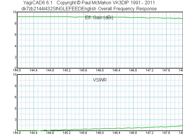
18 Performance Of DK7ZB Dual Band
19 Feedline Low loss feedline important at VHF/UHF Low loss = large diameter RG-8X is OK on 6M for short runs and easily transported Really should use RG-213 or equivalent on 2M and 432 MHz, but bulky and heavy Alternate is to use RG-6, which is low loss and inexpensive 75 Ohms so need to handle mismatch Accept as is Use integer multiples of half wavelengths (remember velocity factor) for feed line length, same on 432 MHz and 144 MHz Make transformers to match 75 Ohm to 50 Ohm
20 Masts Aluminum Painter s Poles Telescope and collapsible Lightweight Camouflage netting support poles Lightweight, but bulky 5 foot TV mast sections Heavy, bulky Keep U-bolts on mast, attach antennas with second set of nuts Bungee cord to available supports Drive on support 2 x 6, floor flange, and nipple to fit inside mast
21 Extra wing nuts Screwdriver Electrical tape Duct tape Hefty diagonal cutters Weld rod Rule Bungee cords Utility cord Velcro ties Spares and Tools
22 Commercial Antennas PAR SM50 stressed Moxon excellent performer and portable Super Yagi 2 element good performer and assembles easily in field Elk 144/432 good performer and has single feedline Arrow Portable satellite antenna has orthogonal polarizations on 144 MHz and 432 MHz, so not as useful Other VHF UHF antennas not really designed for easy assesmbly/disassembly
Inexpensive Lightweight High-Performance Small Yagi Antennas for VHF-UHF Portable Operation
 Inexpensive Lightweight High-Performance Small Yagi Antennas for VHF-UHF Portable Operation Rick Campbell KK7B Pacific Northwest VHF Conference Bend, Oregon October 8 2016 But why? We already have: Inexpensive
Constructing VHF/UHF Antennas WB5CXC Larry Brown W5WF Charles Webb
 Constructing VHF/UHF Antennas WB5CXC Larry Brown W5WF Charles Webb We will be discussing construction of VHF/UHF antenna for portable and home use using common available materials. Our favorite supplies
Portable or Emergency VHF Antennas Paul R. Jorgenson KE7HR
 For emergency or public service events it is often necessary to have more antenna than the rubber duck on your handheld VHF radio. Nearly ANY external antenna will provide more coverage for your handheld
A Folding 5-Element Yagi for 144 MHz
 A Folding 5-Element Yagi for 144 MHz Steve Kavanagh, VE3SMA, April 2017 1. Introduction I have found antennas which fold up quickly to take less space in the car to be useful in VHF/UHF portable operating.
Chapter 6 Antenna Basics. Dipoles, Ground-planes, and Wires Directional Antennas Feed Lines
 Chapter 6 Antenna Basics Dipoles, Ground-planes, and Wires Directional Antennas Feed Lines Some General Rules Bigger is better. (Most of the time) Higher is better. (Most of the time) Lower SWR is better.
INSTRUCTION MANUAL. Specifications Electrical. Front-To-Back Ratio VSWR at Resonance Less than 1.5:1 Nominal Impedance. Mechanical
 300 Industrial Park Road, Starkville, MS 39759 Ph: (662) 323-8538 FAX: (662) 323-6551 TH-3JRS Tri-band HF 3 Elements Beam Covers 10, 15 and 20 Meters INSTRUCTION MANUAL WARNING Installation of this product
BUILD A HIGH PERFORMANCE TWO ELEMENT TRI-BAND CUBICAL QUAD. By Bob Rosier K4OCE INTRODUCTION THEORY AND GENERAL INFORMATION
 BUILD A HIGH PERFORMANCE TWO ELEMENT TRI-BAND CUBICAL QUAD INTRODUCTION By Bob Rosier K4OCE Lots of DX can be worked with a dipole at the QRP level, however, a beam will obviously give you additional gain
4 Antennas as an essential part of any radio station
 4 Antennas as an essential part of any radio station 4.1 Choosing an antenna Communicators quickly learn two antenna truths: Any antenna is better than no antenna. Time, effort and money invested in the
L. B. Cebik, W4RNL. Basic Transmission Line Properties
 L. B. Cebik, W4RNL In the course of developing this collection of notes, I have had occasion to use and to refer to both series and parallel coaxial cable assemblies. Perhaps a few notes specifically devoted
M2 Antenna Systems, Inc. Model No: 2M7
 M2 Antenna Systems, Inc. Model No: 2M7 SPECIFICATIONS: Model... 2M7 Frequency Range... 144 To 148 MHz *Gain... 12.3 dbi Front to back... 20 db Typical Beamwidth... E=43 H=50 Feed type... T Match Feed Impedance....
INSTRUCTION MANUAL. Specifications Mechanical. 1 5/8 to 2 1/16 O.D. (41mm to 52mm)
") 308 Industrial Park Road Starkville, MS 39759 USA Ph: (662) 323-9538 FAX: (662) 323- General Description Model VB-25FM 2-Meter 5 Elements Beam INSTRUCTION MANUAL This antenna is a 5-element, 2-meter beam
308 Industrial Park Road Starkville, MS 39759 USA Ph: (662) 323-9538 FAX: (662) 323- General Description Model VB-25FM 2-Meter 5 Elements Beam INSTRUCTION MANUAL This antenna is a 5-element, 2-meter beam
The EMCOMM Easytenna
 The EMCOMM Easytenna This document will detail how to build an easy to install multiband dipole type antenna for emergency communications using the NVIS propagation mode. History The NVIS mode is one in
Cushcraft. Amateur Radio Antennas LFA-6M5EL. 6 Meter 5 Element Loop Feed Antenna INSTRUCTION MANUAL
 Cushcraft Amateur Radio Antennas LFA-6M5EL 6 Meter 5 Element Loop Feed Antenna INSTRUCTION MANUAL CAUTION: Read All Instructions Before Operating Equipment VERSION 1A Cushcraft Amateur Radio Antennas 308
Antennas Demystified Antennas in Emergency Communications. Scott Honaker N7SS
 Antennas Demystified Antennas in Emergency Communications Scott Honaker N7SS Importance of Antennas Antennas are more important than the radio A $5000 TV with rabbit ears will have a lousy picture Antennas
simple and robust feeding system. No phasing lines or matching devices to worry about. spiderbeam on 10m aluminium push-up pole
 The spiderbeam was developed as a DXpeditioner's dream antenna. It is a full size lightweight tribander yagi made of fiberglass and wire. The whole antenna weight is only kg (lbs), making it ideally suited
Model VB-23FM 2-Meter 3-Element Beam
 308 Industrial Park Road Starkville, MS 39759 USA Ph: (662) 323-9538 FAX: (662) Model VB-23FM 2-Meter 3-Element Beam [ INSTRUCTION MANUAL Figure 1 Overall View and Boom Detail GENERAL DESCRIPTION This
Portable Magnetic Loop Antenna. KG5EAO Rick Bono
 Portable Magnetic Loop Antenna KG5EAO Rick Bono April 2, 2016 Overview Develop a Portable magnetic loop antenna for use on HF bands running QRP. Portable and easy to deploy Ideally run on the 40m through
M2 Antenna Systems, Inc. Model No: 20M5LD
 M2 Antenna Systems, Inc. Model No: 20M5LD SPECIFICATIONS: Model... 20M5LD Frequency Range... 14.0 14.350 MHz *Gain (Full Band)... 10.2 dbi Typical Front to back... 23 db Typical Beamwidth... E=50 / H=66
General License Class Chapter 6 - Antennas. Bob KA9BHD Eric K9VIC
 General License Class Chapter 6 - Antennas Bob KA9BHD Eric K9VIC Learning Objectives Teach you enough to get all the antenna questions right during the VE Session Learn a few things from you about antennas
Traveling Wave Antennas
 Traveling Wave Antennas Antennas with open-ended wires where the current must go to zero (dipoles, monopoles, etc.) can be characterized as standing wave antennas or resonant antennas. The current on these
Construction manual for 50 MHz XL design yagi-kits
 Construction manual for 50 MHz XL design yagi-kits Source: http://www.nuxcom.de/pdf/nuxcom_construction-manual_6m-xl.pdf Please check if all parts listed in the invoice are delivered with the kit. In the
Weekend Antennas No. 5 The "Compact Quad" Multiband Antenna
 Weekend Antennas No. 5 The "Compact Quad" Multiband Antenna When I relocated to Johannesburg I needed a new multiband HF antenna. Since I was staying in a rented house a tower was out of the question,
INSTRUCTION MANUAL. Model VB-215DX MECHANICAL DESIGN GENERAL DESCRIPTION ELECTRICAL DESIGN. 2 Meter 15 Element Yagi for SSB/CW
 Model VB-215DX 2 Meter 15 Element Yagi for SSB/CW INSTRUCTION MANUAL GENERAL DESCRIPTION The Hy-Gain Model 215DX is a high performance yagi antenna for SSB/CW DXing in the Amateur 2 meter band. It features
M2 Antenna Systems, Inc. Model No: 2M5WL
 M2 Antenna Systems, Inc. Model No: 2M5WL SPECIFICATIONS: Model... 2M5WL Frequency Range... 144 To 148 MHz *Gain... 16.84 dbi Front to back... 22 db Typical Beamwidth... E=26 H=29 Feed type... T Match Feed
Intermediate Course (5) Antennas and Feeders
 Antennas and Feeders") Intermediate Course (5) Antennas and Feeders 1 System Transmitter 50 Ohms Output Standing Wave Ratio Meter Antenna Matching Unit Feeder Antenna Receiver 2 Feeders Feeder types: Coaxial, Twin Conductors
Intermediate Course (5) Antennas and Feeders 1 System Transmitter 50 Ohms Output Standing Wave Ratio Meter Antenna Matching Unit Feeder Antenna Receiver 2 Feeders Feeder types: Coaxial, Twin Conductors
THE HENTENNA RE-VISITED
 THE HENTENNA RE-VISITED "The following article has been re-edited for the English language from the Japanese site. Minor errors and corrections have been made." The Hentenna was developed by Japanese 6
CHAPTER 8 ANTENNAS 1
 CHAPTER 8 ANTENNAS 1 2 Antennas A good antenna works A bad antenna is a waste of time & money Antenna systems can be very inexpensive and simple They can also be very expensive 3 Antenna Considerations
M2 Antenna Systems, Inc. Model No: 2M4
 M2 Antenna Systems, Inc. Model No: 2M4 SPECIFICATIONS: Model... 2M4 Frequency Range... 144 To 148 MHz *Gain... 9.6 dbi Front to back... 20 db Typical Beamwidth... E=54 H=74 Feed type... T Match Feed Impedance....
The J-Pole Antenna. Gary Wescom
 The J-Pole Antenna Gary Wescom - 2018 Much has been written about the J-Pole antenna. A simple Google search will net days worth of reading material on the subject. That would tend to indicate this paper
Performance Predicted by YAGI-CAD
 1 of 7 11/16/2010 2:02 PM Joe Leggio WB2HOL Description This antenna evolved during my search for a beam with a really great front-to-back ratio to use in hidden transmitter hunts. This design exhibits
Optimizing Your Stations Performance
 Optimizing Your Stations Performance A few hints / techniques, recommendations for getting the most RF out to the Antenna from your HF, VHF / UHF station. Tonights Presenters: Doug Theriault NO1D John
The DBJ-1: A VHF-UHF Dual-Band J-Pole
 By Edison Fong, WB6IQN The DBJ-1: A VHF-UHF Dual-Band J-Pole Searching for an inexpensive, high-performance dual-band base antenna for VHF and UHF? Build a simple antenna that uses a single feed line for
M2 Antenna Systems, Inc. Model No: 2MCP22
 M2 Antenna Systems, Inc. Model No: 2MCP22 SPECIFICATIONS: Model... 2MCP22 Frequency Range... 144 To 148 MHz *Gain... 14.39 dbic Front to back... 25 db Typical Elipticity... >3db Beamwidth... 38 Feed type...
M2 Antenna Systems, Inc. Model No: 20M6-125
 M2 Antenna Systems, Inc. Model No: 20M6-125 SPECIFICATIONS: Model... 20M6-125 Frequency Range... 14.0 14.350 MHz *Gain, (FS) / Over gnd... 11.19dBi / 16.6dBi @70 Front to back... 25 db Typical Beamwidth...
TZ-RD-1740 Rotary Dipole Instruction Manual
 TZ-RD-1740 17/40m Rotary Dipole Instruction Manual The TZ-RD-1740 is a loaded dipole antenna for the 40m band and a full size rotary dipole for the 17m band. The antenna uses an aluminium radiating section
Resonant Antennas: Wires and Patches
 Resonant Antennas: Wires and Patches Dipole Antennas Antenna 48 Current distribution approximation Un-normalized pattern: and Antenna 49 Radiating power: For half-wave dipole and,, or at exact resonance.
MFJ-1762 Instruction Manual
 MFJ-1762 Instruction Manual INTRODUCTION Thank you for purchasing the MFJ-1762 three-element six-meter Yagi. The MFJ-1762 is a light-weight directional antenna especially designed for installation with
PAC-12 Kit Contents. Tools Needed Soldering iron Phillips screwdriver Wire stripper Wrenches, 7/16 and 1/2 Terminal crimp tool Pliers Solder
 PAC-2 Kit Contents Part Quantity Screws: 8/32 x 3/8 Screws: 8-32 x 5/6 Screw: 8-32 x /4 #8 internal tooth washers #8 solder lug ring terminals Bolt: Aluminum, /4-20 x.5 /4 internal tooth washer Nut: Aluminum
Technician Licensing Class. Lesson 4. presented by the Arlington Radio Public Service Club Arlington County, Virginia
 Technician Licensing Class Lesson 4 presented by the Arlington Radio Public Service Club Arlington County, Virginia 1 Quiz Sub elements T6 & T7 2 Good Engineering Practice Sub element T8 3 A Basic Station
Nick Garner N3WG and George Zafiropoulos KJ6VU
 Nick Garner N3WG and George Zafiropoulos KJ6VU Introduction Over the last few years, there has been a significant increase in the number of radio amateurs interested in portable operating. This is due
The Quagi Antenna Turns 30
 The Quagi Antenna Turns 30 By Wayne Overbeck, N6NB www.n6nb.com It has been 30 years since the VHF-UHF Quagi antenna--a combination of the desirable features of a Yagi and a cubical quad--was developed
A Reversible Vertical Moxon for 20M
 A Reversible Vertical Moxon for 20M I decided to try a vertical moxon rectangle at my new QTH which has limited rear garden space. The rear garden runs roughly NW to SE, so a reversible moxon gives useful
M2 Antenna Systems, Inc. Model No: 2M HO LOOP
 M2 Antenna Systems, Inc. Model No: 2M HO LOOP SPECIFICATIONS: Model... 2M HO LOOP Frequency Range... 144 To 144.5 MHz Gain, Typical @ 10 ft.... 4 dbd @ 10 deg. Gain, 2 STK @ 82 & 132... 8 dbd @ 9 deg.
A IVE-BAND, TWO-ELEMENT H QUAD
 A IVE-BAND, TWO-ELEMENT H QUAD Two quad designs are described in this article, both nearly identical. One was constructed by KC6T from scratch, and the other was built by Al Doig, W6NBH, using modified
9 Element Yagi for 2304 MHz
 9 Element Yagi for 2304 MHz Steve Kavanagh, VE3SMA Design Dipole-based Yagi designs for 2304 MHz are rare, partly because they are a bit tricky to build and partly because the loop yagi has completely
CP6 6 Band Trap Vertical 80-6m
 CP6 6 Band Trap Vertical 80-6m Instruction Sheet The CP6 is a multi-band trap-vertical antenna for HF bands, covering the 80*, 40, 20, 15, 10m & 6m amateur bands. Made from heavy duty aluminum, the CP6
VHF/UHF Beyond FM Bob Witte KØNR Page 1
 VHF/UHF Beyond FM Technical Coordinator Colorado Section Page 1 Objective The objective of this presentation is to provide an introduction to operating on VHF/UHF, going beyond the usual FM / Repeater
M2 Antenna Systems, Inc. Model No: 436CP30
 M2 Antenna Systems, Inc. Model No: 436CP30 SPECIFICATIONS: Model... 436CP30 Frequency Range... 432 To 440 MHz *Gain... 15.50 dbic Front to back... 18 db Typical Elipticity... 1.5 db Typical Beamwidth...
Least understood topics by most HAMs RF Safety Ground Antennas Matching & Feed Lines
 Least understood topics by most HAMs RF Safety Ground Antennas Matching & Feed Lines Remember this question from the General License Exam? G0A03 (D) How can you determine that your station complies with
9el 144MHZ LFA YAGI ASSEMBLY & INSTALLATION MANUAL
 1 9el 144MHZ LFA YAGI ASSEMBLY & INSTALLATION MANUAL 2 WARNING EXTREME CAUTION SHOULD BE TAKEN WHEN CONSTRUCTING AND ERECTING ANTENNA SYSTEMS NEAR POWER AND TELEPHONE LINES. SERIOUS INJURY OR DEATH CAN
A 6-Meter Quad-Turnstile
 By L. B. Cebik, W4RNL A 6-Meter Quad-Turnstile Looking for improved omnidirectional, horizontally polarized performance? This 6-meter turnstile uses the quad loop as a foundation. Turnstile Principles
Last year I described several Low Band RX antennas that would enable you to hear DX stations on 160, 80 and 40M. This will show you how to build
 Last year I described several Low Band RX antennas that would enable you to hear DX stations on 160, 80 and 40M. This will show you how to build transmit antennas that will help you break the pileups!
UNIVERSITI MALAYSIA PERLIS
 UNIVERSITI MALAYSIA PERLIS SCHOOL OF COMPUTER & COMMUNICATIONS ENGINEERING EKT 341 LABORATORY MODULE LAB 2 Antenna Characteristic 1 Measurement of Radiation Pattern, Gain, VSWR, input impedance and reflection
NVIS, Another Look. Tom Sanders, W6QJI Ed Bruette, N7NVP
 NVIS, Another Look Tom Sanders, W6QJI Ed Bruette, N7NVP Regional Communications N.V.I.S. Near Vertical Incidence Skywave What is NVIS? Near Vertical Incident Skywave Cloud Warmer Propagation Theory NVIS
Technician Licensing Class T9
 Technician Licensing Class T9 Amateur Radio Course Monroe EMS Building Monroe, Utah January 11/18, 2014 January 22, 2014 Testing Session Valid dates: July 1, 2010 June 30, 2014 Amateur Radio Technician
TELEX, liutiiilio"i TELEX COMMUNICATIONS, INC ALDRICH AVE. SO. MINNEAPOLIS. MN USA
 TELEX, liutiiilio"i TELEX COMMUNICATIONS, INC. 9600 ALDRICH AVE. SO. MINNEAPOLIS. MN 55420 USA INSTRUCTION MANUAL ORDER NO. 410 General This antenna is a five-element, Citizens Band beam with a forward
2.3GHz Dish Feed Antenna
 I have not been convinced my very old 2.3GHz 44 element Loop Yagi has been working as well as it should do, particularly as the elements have become severely corroded over the years. I decided to see if
M2 Antenna Systems, Inc. Model No: 456CP34
 M2 Antenna Systems, Inc. Model No: 456CP34 SPECIFICATIONS: Model... 456CP34 Frequency Range... 435 To 470 mhz *Gain... 16.0 dbi Front to back... 23 db Typical Beamwidth... 30 Circular Feed type... T Match
4/25/2012. Supplement T9. 2 Exam Questions, 2 Groups. Amateur Radio Technician Class T9A: T9A: T9A: T9A:
 Amateur Radio Technician Class Element 2 Course Presentation ti ELEMENT 2 SUB-ELEMENTS Technician Licensing Class Supplement T9 Antennas, Feedlines 2 Exam Questions, 2 Groups T1 - FCC Rules, descriptions
Milton Keynes Amateur Radio Society (MKARS)
") Milton Keynes Amateur Radio Society (MKARS) Intermediate Licence Course Feeders Antennas Matching (Worksheets 31, 32 & 33) MKARS Intermediate Licence Course - Worksheet 31 32 33 Antennas Feeders Matching
Milton Keynes Amateur Radio Society (MKARS) Intermediate Licence Course Feeders Antennas Matching (Worksheets 31, 32 & 33) MKARS Intermediate Licence Course - Worksheet 31 32 33 Antennas Feeders Matching
M2 Antenna Systems, Inc. Model No: 435XP50
 M2 Antenna Systems, Inc. Model No: 435XP50 SPECIFICATIONS: Model... 435XP50 Frequency Range... 430 To 436 MHz *Gain... 19.2 dbi Front to back... 22 db Typical Cross pol. isolation... >20 db Typical Beamwidth...
Yagi beam antennas CHAPTER 10 COMPOSITION OF A BEAM ANTENNA _
 CHAPTER 10 Yagi beam antennas The Yagi beam antenna (more correctly, the Yagi Uda antenna, after both of the designers of Tohoku University in Japan 1926) is unidirectional. It can be vertically polarized
Build the PAC-12 Antenna
 Build the PAC-12 Antenna a multi-band portable vertical designed by KA5DVS Here s an award-winning, easy-to-homebrew, multi-band portable vertical antenna designed by long-time antenna aficionado James
Antenna Circular Polarization
 Antenna Circular Polarization Space communication has forced the use of Circular polarization. The fundamental advantage of circular polarization is that all reflections change the direction of polarization,
INSTRUCTION MANUAL ORDER NO. V3R MODEL V3R. Collinear Gain Vertical for MHz
 ORDER NO. V3R MODEL V3R Collinear Gain Vertical for 216-225 MHz INSTRUCTION MANUAL General Description The new Hy-Gain V3R VHF antenna is a collinear 5/8-wave omnidirectional vertical antenna for the 216-225
Antenna Design for FM-02
 Antenna Design for FM-02 I recently received my FM-02 FM transmitter which I purchased from WLC. I researched the forum on what antennas where being used by the DIY community and found a nice write-up
M2 Antenna Systems, Inc. Model No: 450CP34
 M2 Antenna Systems, Inc. Model No: 450CP34 SPECIFICATIONS: Model... 450CP34 Frequency Range... 435 To 455 mhz *Gain... 16.0 dbi Front to back... 22 db Typical Beamwidth... 28 Circular Feed type... T Match
Directive Systems & Engineering 2702 Rodgers Terrace Haymarket, VA
 Directive Systems & Engineering 2702 Rodgers Terrace Haymarket, VA 20169 1628 www.directivesystems.com 703 754 3876 K1JX DESIGNED 6 ELEMENT 50 MHZ YAGI, DSEJX6 50 INTRODUCTION The Directive Systems DSEJX6-50
THE W3FF HOMEBREW BUDDIPOLE
 THE W3FF HOMEBREW BUDDIPOLE A PORTABLE ANTENNA DESIGN FOR AMATEUR RADIO History of the Buddipole In January of 2000, I began experimenting with a walking portable ham station. Since then, thousands of
Pacific Antenna 20 and 40M Lightweight Dipole Kit
 Pacific Antenna 20 and 40M Lightweight Dipole Kit Diagram showing configuration and approximate lengths 8 3 16 9 16 9 8 3 Description The Pacific Antenna lightweight dual band, trap dipole kit provides
M2 Antenna Systems, Inc. Model No: KT31WARC
 M2 Antenna Systems, Inc. Model No: KT31WARC SPECIFICATIONS: Model... KT31WARC Frequency Range... 10.1-10.15 MHz **Selectable Frequency Range... 14.0-14.35 MHz **Selectable... (175 KHz / 2:1 VSWR Nominal)
Newsletter of the Aberdeen Amateur Radio Society CARRIER WAVE. We start this newsletter with some not so good news.
 CARRIER WAVE October 2005 Aberdeen Amateur Radio Society We start this newsletter with some not so good news. Stuart McNicol GM3UU is now a silent key. He passed away on the 11th August in his 99th year
M2 Antenna Systems, Inc. Model No: 450CP26
 M2 Antenna Systems, Inc. Model No: 450CP26 SPECIFICATIONS: Model... 450CP26 Frequency Range... 445 To 455 mhz *Gain... 16.5 dbi Front to back... 21 db Typical Beamwidth... 30 Circular Feed type... T Match
TELEX. iiilhiijiri INSTRUCTION MANUAL ORDER NO. 411 TELEX COMMUNICATIONS, INC ALDRICH AVE SO. MINNEAPOLIS. MN U.SA.
 TELEX. iiilhiijiri TELEX COMMUNICATIONS, INC. 9600 ALDRICH AVE SO. MINNEAPOLIS. MN 55420 U.SA. INSTRUCTION MANUAL ORDER NO. 411 Base Station, 5-Element Beam Antenna This antenna is a five element, Citizens
DB Duo-Monoband Beam 7 - Element, 12 and 17 Meter INSTRUCTION MANUAL. General Description
 308 Industrial Park Road Starkville, MS 39759 USA Ph: (662) 323-9538 FAX: (662) 323-6551 DB- 1217 Duo-Monoband Beam 7 - Element, 12 and 17 Meter INSTRUCTION MANUAL General Description The Hy-Gain DB-1217
Adjust Antenna Tuners Antenna Measurements Capacitor Measurement Measure Feed Point Impedance Measure Ground Loss Inductor Measurement
 The Micro908 antenna analyzer is an extremely useful instrument to have around the ham shack or homebrewer s workbench. This section describes the basic uses, as well as some advanced techniques for which
INSTRUCTION MANUAL V-42R. Dual Band Collinear Gain Vertical for MHz and GENERAL DESCRIPTION
 308 Industrial Park Road, Starkville, MS 39759 USA Ph: (662) 323-9538 FAX: (662) 323-6551 V-42R Dual Band Collinear Gain Vertical for 144-148 MHz and 436-450 INSTRUCTION MANUAL GENERAL DESCRIPTION The
Band I (Low VHF) TV Panel Arrays MHz. 606L Series BROADCAST ANTENNA SYSTEMS
 TV Panel Arrays MHz. 606L Series BROADCAST ANTENNA SYSTEMS") Band I (Low VHF) TV Panel Arrays 44-88 MHz L Series The L series of panels are low wind load antennas suitable to provide a customized coverage for any single TV channel in Band I. Low wind load Pressurizable
Band I (Low VHF) TV Panel Arrays 44-88 MHz L Series The L series of panels are low wind load antennas suitable to provide a customized coverage for any single TV channel in Band I. Low wind load Pressurizable
N5PUV s 4 Band Fan Dipole Experiment. Using the New SRI (Stanford Research Institute) Method
 Method") N5PUV s 4 Band Fan Dipole Experiment Using the New SRI (Stanford Research Institute) Method Goals of Experiment Develop a Multi-band Antenna that does NOT require a tuner Build using the new, easier tuning
N5PUV s 4 Band Fan Dipole Experiment Using the New SRI (Stanford Research Institute) Method Goals of Experiment Develop a Multi-band Antenna that does NOT require a tuner Build using the new, easier tuning
K1FO 12 ELEMENT 144/147 MHz YAGI
 K1FO 12 ELEMENT 144/147 MHz YAGI WARNING: INSTALLATION OF THIS PRODUCT NEAR POWER LINES IS DANGEROUS. FOR YOUR SAFETY FOLLOW THE INSTALLATION DIRECTIONS. Ariane Arrays, Inc. Copyright 2006 201 Hopedale
A Triangle for the Short Vertical
 1 von 11 03.03.2015 12:37 A Triangle for the Short Vertical Operator L. B. Cebik, W4RNL Last month, I described a triangle array of three full-size vertical dipoles for 40 meters (with 30 meters as a bonus).
Ten-Tec Model 3402 and 3403 Broadband Antennas Installation and Operation Manual PN 74393
 1. Introduction Ten-Tec Model 3402 and 3403 Broadband Antennas Installation and Operation Manual PN 74393 The Ten-Tec Model 3402 Broadband Terminated Vee Beam Antenna offers continuous coverage between
By Paul Melbourne G8GML and Ian Waters G3KKD.
 23cm Panel Antennas By Paul Melbourne G8GML and Ian Waters G3KKD. This article describes a range of panel antennas developed by G8GML. It is a sequel to an article by John Stockley, G8MMY, published in
LJ element beam for 10 or 12 meters INSTRUCTION MANUAL. CAUTION: Read All Instructions Before Operating Equipment
 LJ-113 3 element beam for 10 or 1 meters INSTRUCTION MANUAL CAUTION: Read All Instructions Before Operating Equipment 308 Industrial Park Road Starkville, MS 39759 USA Tel: 66-33-9538 Fax: 66-33-6551 VERSION
4/29/2012. General Class Element 3 Course Presentation. Ant Antennas as. Subelement G9. 4 Exam Questions, 4 Groups
 General Class Element 3 Course Presentation ti ELEMENT 3 SUB ELEMENTS General Licensing Class Subelement G9 Antennas and Feedlines 4 Exam Questions, 4 Groups G1 Commission s Rules G2 Operating Procedures
Improved Ionospheric Propagation With Polarization Diversity, Using A Dual Feedpoint Cubical Quad Loop
 Improved Ionospheric Propagation With Polarization Diversity, Using A Dual Feedpoint Cubical Quad Loop by George Pritchard - AB2KC ab2kc@optonline.net Introduction This Quad antenna project covers a practical
The Fabulous Dipole. Ham Radio s Most Versatile Antenna
 The Fabulous Dipole Ham Radio s Most Versatile Antenna 1 What is a Dipole? Gets its name from its two halves One leg on each side of center Each leg is the same length It s a balanced antenna The voltages
Cushcraft. Amateur Radio Antennas DB-46M8EL. Dual band 6 and 4 Meter, 8 Element Beam Antenna INSTRUCTION MANUAL
 Cushcraft Amateur Radio Antennas DB-46M8EL Dual band 6 and 4 Meter, 8 Element Beam Antenna INSTRUCTION MANUAL CAUTION: Read All Instructions Before Operating Equipment VERSION 1B Cushcraft Amateur Radio
ANTENNA DESIGN FOR FREE USING MMANA-GAL SOFTWARE
 ANTENNA DESIGN FOR FREE USING MMANA-GAL SOFTWARE 1. AVAILABLE ANTENNA DESIGN SOFTWARE EZNEC and 4nec2 are based upon the Numerical Electromagnetics Code, or NEC, which is a popular antenna modelling system
MQ-24SR Miniature Four band Hybrid Quad Antenna
 MQ-24SR Miniature Four band Hybrid Quad Antenna Most antennas are large heavy structures requiring heavy duty structures, rotors and lots of extra muscle during installation and lots of extra dollars before
THIS SHOULD TWEAK YOUR IMAGINATION
 10-27-05 THIS SHOULD TWEAK YOUR IMAGINATION SPECIFICATIONS FOR SINGLE ANTENNA MODEL NUMBER... 432EME-12 FREQUENCY... 430-436 MHz GAIN... 14.4 dbd FRONT TO BACK... 23 db VSWR... 1.2:1 TYPICAL BEAMWIDTH...
MOUNTING INSTRUCTIONS
 Standard Mounting Bracket Tilting Bracket* Mounting example Right side for upper tilt from 0 to 20 20 Spare parts: p/n SA197 Materials: extruded aluminum Hardware: stainless & zinc plated steel Dimensions
Travelling Wave, Broadband, and Frequency Independent Antennas. EE-4382/ Antenna Engineering
 Travelling Wave, Broadband, and Frequency Independent Antennas EE-4382/5306 - Antenna Engineering Outline Traveling Wave Antennas Introduction Traveling Wave Antennas: Long Wire, V Antenna, Rhombic Antenna
M2 Antenna Systems, Inc. Model No: YAGI ANTENNA
 M Antenna Systems, Inc. Model No: 4.5-7 YAGI ANTENNA SPECIFICATIONS: Model... 4.5-7 Frequency Range... 4.0 To 4.5 MHz *Gain... 0 To 7 dbi Front to back... 0 db over the rear 80 Beamwidth... E=44 H=50 typical
Portable Vertical Antenna Counterpoise Kit (CHA COUNTERPOISE KIT) Operator s Manual
 Operator s Manual") Portable Vertical Antenna Counterpoise Kit (CHA COUNTERPOISE KIT) Operator s Manual Nevada - USA WWW.CHAMELEONANTENNA.COM VERSATILE DEPENDABLE STEALTH BUILT TO LAST Table of Contents Introduction... 3
Portable Vertical Antenna Counterpoise Kit (CHA COUNTERPOISE KIT) Operator s Manual Nevada - USA WWW.CHAMELEONANTENNA.COM VERSATILE DEPENDABLE STEALTH BUILT TO LAST Table of Contents Introduction... 3
J-Poles. Mythbusting J-Pole Antennas
 Mythbusting J-Pole Antennas For an antenna to work correctly, it must do two things well 1) Accept power from the feed line impedance match, SWR (ideally) 1:1 2) Radiate power in a pattern that is useful
New Antenna Designs for DTV Implementation
 New Antenna Designs for DTV Implementation JOHN L. SCHADLER and KERRY COZAD Dielectric Communications Raymond, Maine ABSTRACT WIDE BAND CAVITY ANTENNA (TFU-WB) Over the past few years the implementation
EE 172 Final Project Report. 915 MHz Cantenna and Patch Antennas Design. By: Sawson Teheri Jared Buckley Ramon Alvarado
 EE 172 Final Project Report 915 MHz Cantenna and Patch Antennas Design By: Sawson Teheri Jared Buckley Ramon Alvarado May 25, 2004 Abstract: A 915 MHz antennas will be designed, constructed, measured and
MFJ-219/219N 440 MHz UHF SWR Analyzer TABLE OF CONTENTS
 MFJ-219/219N 440 MHz UHF SWR Analyzer TABLE OF CONTENTS Introduction...2 Powering The MFJ-219/219N...3 Battery Installation...3 Operation Of The MFJ-219/219N...4 SWR and the MFJ-219/219N...4 Measuring
Portable Antenna Spike Mount (CHA SPIKE MOUNT) Operator s Manual
 Operator s Manual") Portable Antenna Spike Mount (CHA SPIKE MOUNT) Operator s Manual Nevada - USA WWW.CHAMELEONANTENNA.COM VERSATILE DEPENDABLE STEALTH BUILT TO LAST Table of Contents Introduction... 3 Parts of the Spike
Portable Antenna Spike Mount (CHA SPIKE MOUNT) Operator s Manual Nevada - USA WWW.CHAMELEONANTENNA.COM VERSATILE DEPENDABLE STEALTH BUILT TO LAST Table of Contents Introduction... 3 Parts of the Spike