M2 Antenna Systems, Inc. Model No: 2M4
|
|
|
- Moses George
- 5 years ago
- Views:
Transcription


1 M2 Antenna Systems, Inc. Model No: 2M4 SPECIFICATIONS: Model... 2M4 Frequency Range To 148 MHz *Gain dbi Front to back db Typical Beamwidth... E=54 H=74 Feed type... T Match Feed Impedance Ohms Unbalanced Maximum VSWR :1 Input Connector... N Female Power Handling kw Boom Length / Dia / 1 Maximum Element Length /2 Turning Radius: Stacking Distance High & 80 Wide Mast Size /2 to 2 Nom. Wind area / Survival Sq. Ft. / 100 MPH Weight / Ship Wt Lbs. / 4 Lbs. *Subtract 2.14 from dbi for dbd FEATURES: Clean mechanical design, full band coverage and computer optimized performance make the 2M4 an exceptional antenna. A totally sealed and grounded driven element design with a unique internal balun provides the heart that will beat for years to come. It is perfect for base and portable use, with FM, Packet or SSB. Every station needs one!!! M2 Antenna Systems, Inc N. Selland Ave. Fresno, CA Tel: (559) Fax: (559) Web: M2 Antenna Systems Incoporated 05/26/15 Rev.01
 element. Balance on finger to find rough center and push on a black button insulator to about 1/2 from center.")

2 2M4 ASSEMBLY MANUAL Tools handy for assembly process: screwdriver, 11/32 spin-tite or socket, 7/16 and 1/2 end wrenches / sockets, measuring tape. 1. Lay out the elements by length and position as shown the DIMENSION sheet. Start with the REFLECTOR (longest) element. Balance on finger to find rough center and push on a black button insulator to about 1/2 from center. Push the element through the holes 10" from the rear of the boom and install the second button, snugging it up into boom. DO NOT BOTHER WITH ACCURATELY CENTERING the element at this time and DO NOT INSTALL the stainless steel SHAFT RETAINERS yet. This is easier to do after all the elements are installed in the boom. Install the 3/16 rod DRIVEN ELEMENT as you did the reflector and then the DIRECTORS. 2. Now accurately center the elements. Use a tape measure to EQUALIZE the amount the element sticking out on each side of the boom. Begin installing the stainless SHAFT RETAINERS. Use thumb and index finger to hold a retainer over end of the 3/8 x 3 push tube (retainer dished into tube). Hold the element firmly and start the retainer onto the rod by applying pressure with the push tube. Push the retainer until up tight against the button insulator (Locking pliers, lightly clamped up against opposite button insulator will help maintain center reference and keep you from pushing the first retainer too far). Repeat for the opposite side. Continue installing retainers until all elements are locked in place. 3. Mount the T MATCH BLOCK ASSEMBLY to the top of the boom using a single 8-32 X 1-1/4" screw. Orient the block with feed connector facing the rear and balun connectors facing forward. 4. Before installing the balun, thread a 3/8 SEAL NUT all the way onto each connector, with the black Neoprene face of the nuts facing out. Attach balun to the Block and tighten the connectors gently using a 7/16" end wrench. Once the connectors are tight, back the Seal Nuts out and finger-tighten firmly up against the face of the connectors (or tighten gently with 1/2 end wrench). A lot of torque is unnecessary. Form the balun close to the boom and secure with a nylon cable tie. Tie should be snug but not crushing or kinking the coax.
3 2M4 ASSEMBLY MANUAL 5. Install the 8-32 x 1/4 set screws (internal Allen head - tool supplied) into the SHORTING BARS. Slide the bars onto the 3/16 rod driven element tips and then onto the Driven Element Block Rods. Position the Shorting Bars as specified on the Dimension Sheet: 1-3/4. Align the bars and rods with each other and tighten the setscrews. 6. Insert the 7/8 x 9 REINFORCING SLEEVE into the rear of boom, flush with end. The boom to mast plate is normally mounted at the rear. Use two 1" U-bolts and the stainless nuts and lock washers provided (cradles are not used). DO NOT OVER TIGHTEN. 2 U-bolts are provided for mounting the antenna to your mast. THIS COMPLETES THE ANTENNA ASSEMBLY. 7. INSTALLATION AND STACKING INFORMATION A. To protect your investment in this high performance antenna, always use high quality coax and connectors. Old, corroded, or poor quality materials are common sources of serious performance losses. B. If possible, test the antenna, connectors and feedline BEFORE installing to your mast or tower. At 6 feet or more the antenna will exhibit VSWR similar to higher mounting heights. Set antenna on a ladder or temporary mast. Check for continuity and match across the rated bandwidth. C. REAR MOUNTING: The 2M4 is easily rear-mounted in either horizontal or vertical polarity. A metal mast or crossboom will have no effect on performance. D. CENTER MOUNTING: Metal masts or crossbooms are OK for center mounting the antenna IF they are at right angles to the element plane. ALWAYS use a NON-CONDUCTIVE mast or crossboom IF it will be in the element plane. A metal mast in the element plane WILL adversely affect performance. The feed coax, too, if routed to the center, must exit the boom at right angles to the element plane. For example, with a vertically polarized antenna on a vertical nonconductive mast, loop the coax out at a right angle from the elements and reattach to mast at least 6 below the element tips. Or, the coax can exit the rear of the boom and loop back to the mast. Fiberglass is the prime material for a non-conductive mast because of it s strength and weather resistance. Wooden rod can also be used or thick-wall PVC pipe with a wooden rod inside for support. Carefully manufactured by: M 2 ANTENNA SYSTEMS, INC N. Selland Ave. Fresno, CA (559) Fax: sales@m2inc.com

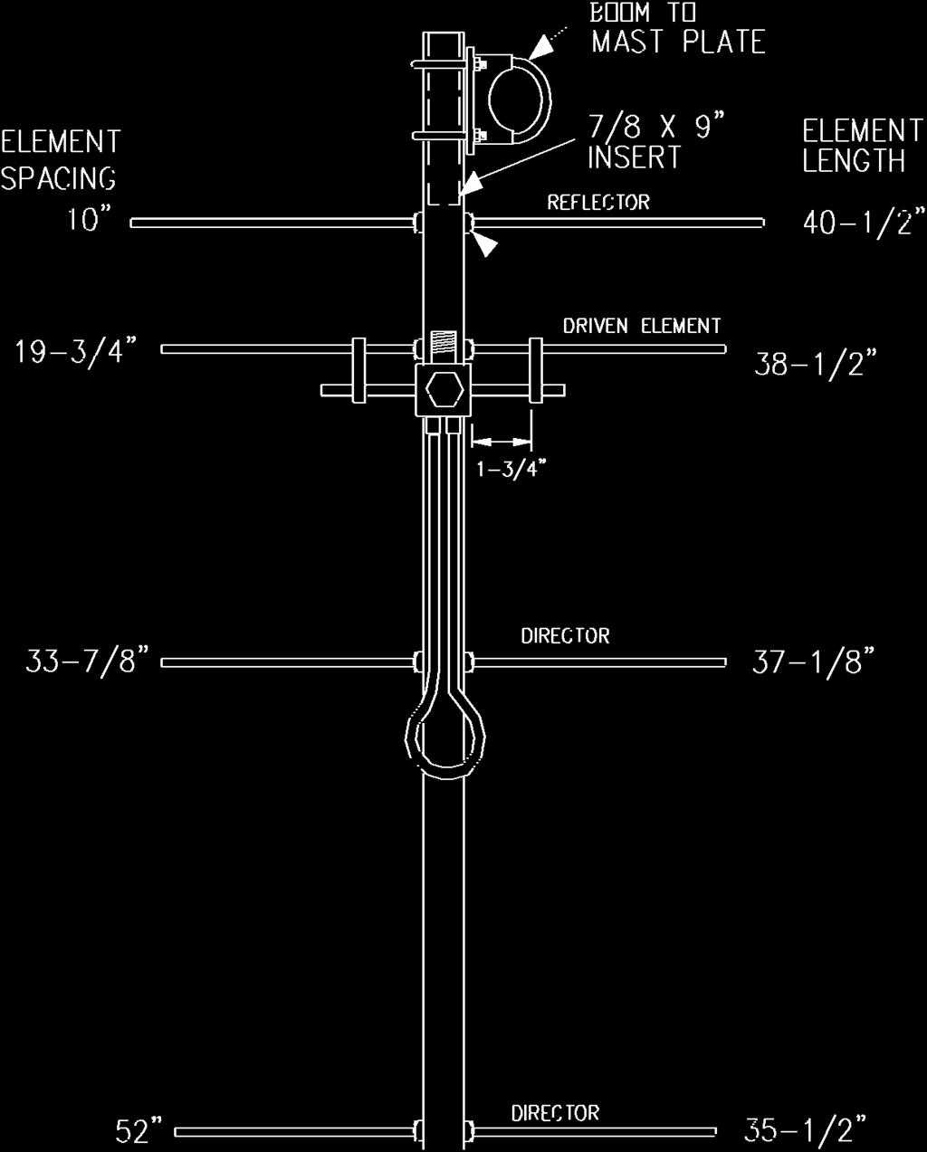
4 2M4 DIMENSION SHEET
5 2M4 PARTS & HARDWARE Description Qty Boom, 1 x.058 x 53" alum Boom insert, 7/8 x.058 x 9.0" alum Elements, 3/16" rod alum T match block &1/4 rods... 1 BTM plate, 3 x 4 x 1/8 (M2APT0019)... 1 Balun, RG U-bolt and cradle, 2"... 2 U-bolt, 1"... 2 Assembly instructions... 1 Hardware Bag Shorting Bar (M2ASB0090)... 2 Nut, 5/16-18 ss... 4 Lock washer, 5/16" split ring ss... 4 Nut, 1/4-20 ss... 4 Lock washer, 1/4" split ring ss... 4 Setscrew, 8-32 x 1/4 int. Allen head, ss... 4 Screw, 8-32 x 1-1/4" pan head ss... 1 Seal Nut... 2 Button insulator 3/16" black polyethylene... 8 Shaft retainer, 3/16" ss... 8 Push tube, 3 x 3/16" (retainer tool)... 1 Allen wrench, 5/64"... 1 Cable tie... 3 M 2 ANTENNA SYSTEMS, INC N. Selland Ave. Fresno, CA (559) Fax: sales@m2inc.com
M2 Antenna Systems, Inc. Model No: 2M7
 M2 Antenna Systems, Inc. Model No: 2M7 SPECIFICATIONS: Model... 2M7 Frequency Range... 144 To 148 MHz *Gain... 12.3 dbi Front to back... 20 db Typical Beamwidth... E=43 H=50 Feed type... T Match Feed Impedance....
M2 Antenna Systems, Inc. Model No: 450CP26
 M2 Antenna Systems, Inc. Model No: 450CP26 SPECIFICATIONS: Model... 450CP26 Frequency Range... 445 To 455 mhz *Gain... 16.5 dbi Front to back... 21 db Typical Beamwidth... 30 Circular Feed type... T Match
M2 Antenna Systems, Inc. Model No: 456CP34
 M2 Antenna Systems, Inc. Model No: 456CP34 SPECIFICATIONS: Model... 456CP34 Frequency Range... 435 To 470 mhz *Gain... 16.0 dbi Front to back... 23 db Typical Beamwidth... 30 Circular Feed type... T Match
M2 Antenna Systems, Inc. Model No: 436CP30
 M2 Antenna Systems, Inc. Model No: 436CP30 SPECIFICATIONS: Model... 436CP30 Frequency Range... 432 To 440 MHz *Gain... 15.50 dbic Front to back... 18 db Typical Elipticity... 1.5 db Typical Beamwidth...
M2 Antenna Systems, Inc. Model No: 450CP34
 M2 Antenna Systems, Inc. Model No: 450CP34 SPECIFICATIONS: Model... 450CP34 Frequency Range... 435 To 455 mhz *Gain... 16.0 dbi Front to back... 22 db Typical Beamwidth... 28 Circular Feed type... T Match
M2 Antenna Systems, Inc. Model No: 2MCP22
 M2 Antenna Systems, Inc. Model No: 2MCP22 SPECIFICATIONS: Model... 2MCP22 Frequency Range... 144 To 148 MHz *Gain... 14.39 dbic Front to back... 25 db Typical Elipticity... >3db Beamwidth... 38 Feed type...
THIS SHOULD TWEAK YOUR IMAGINATION
 10-27-05 THIS SHOULD TWEAK YOUR IMAGINATION SPECIFICATIONS FOR SINGLE ANTENNA MODEL NUMBER... 432EME-12 FREQUENCY... 430-436 MHz GAIN... 14.4 dbd FRONT TO BACK... 23 db VSWR... 1.2:1 TYPICAL BEAMWIDTH...
M2 Antenna Systems, Inc. Model No: 2M5WL
 M2 Antenna Systems, Inc. Model No: 2M5WL SPECIFICATIONS: Model... 2M5WL Frequency Range... 144 To 148 MHz *Gain... 16.84 dbi Front to back... 22 db Typical Beamwidth... E=26 H=29 Feed type... T Match Feed
M2 Antenna Systems, Inc. Model No: 435XP50
 M2 Antenna Systems, Inc. Model No: 435XP50 SPECIFICATIONS: Model... 435XP50 Frequency Range... 430 To 436 MHz *Gain... 19.2 dbi Front to back... 22 db Typical Cross pol. isolation... >20 db Typical Beamwidth...
M2 Antenna Systems, Inc. Model No: 20M6-125
 M2 Antenna Systems, Inc. Model No: 20M6-125 SPECIFICATIONS: Model... 20M6-125 Frequency Range... 14.0 14.350 MHz *Gain, (FS) / Over gnd... 11.19dBi / 16.6dBi @70 Front to back... 25 db Typical Beamwidth...
M2 Antenna Systems, Inc. Model No: YAGI ANTENNA
 M Antenna Systems, Inc. Model No: 4.5-7 YAGI ANTENNA SPECIFICATIONS: Model... 4.5-7 Frequency Range... 4.0 To 4.5 MHz *Gain... 0 To 7 dbi Front to back... 0 db over the rear 80 Beamwidth... E=44 H=50 typical
M2 Antenna Systems, Inc. Model No: 20M5LD
 M2 Antenna Systems, Inc. Model No: 20M5LD SPECIFICATIONS: Model... 20M5LD Frequency Range... 14.0 14.350 MHz *Gain (Full Band)... 10.2 dbi Typical Front to back... 23 db Typical Beamwidth... E=50 / H=66
M2 Antenna Systems, Inc. Model No: KT31WARC
 M2 Antenna Systems, Inc. Model No: KT31WARC SPECIFICATIONS: Model... KT31WARC Frequency Range... 10.1-10.15 MHz **Selectable Frequency Range... 14.0-14.35 MHz **Selectable... (175 KHz / 2:1 VSWR Nominal)
M2 Antenna Systems, Inc. Model No: 10-30LP8
 M2 Antenna Systems, Inc. Model No: 10-30LP8 SPECIFICATIONS: Model... 10-30LP8 Frequency Range... 10-30 MHz Continuous *Gain free space / 65... 5.2 dbi / 10.5 dbi 10-30 Front to back... 15 db 10-30 MHz
M2 Antenna Systems, Inc. Model No: 10-30LP8
 M2 Antenna Systems, Inc. Model No: 10-30LP8 VSWR 2:1 TYPICAL VSWR @ 70 FT. 2:1 1.5:1 1.5:1 1.2:1 1.2:1 10 14 MHz 11 12 13 17 15 16 18 19 20 21 22 23 24 25 26 27 28 29 30 SPECIFICATIONS: Model...10-30LP8
M2 Antenna Systems, Inc. Model No: 40M3L
 M2 Antenna Systems, Inc. Model No: 40M3L SPECIFICATIONS: Model... 40M3L Frequency Range... 7.0-7.3 MHz X 150 khz Gain... 6.6 dbi Front to back... 23 db Beamwidth... E=62 Feed type... Hair pin match Feed
M2 Antenna Systems, Inc. Model No: 6M8GJ
 M2 Antenna Systems, Inc. Model No: 6M8GJ SPECIFICATIONS: Model... 6M8GJ Frequency Range... 50.0 To 50.4 mhz *Gain, (FS) / Over gnd... 14.2 dbi / 19 dbi @ 20 Front to back... 20 db Typical Beamwidth...
M2 Antenna Systems, Inc. Model No: 2M HO LOOP
 M2 Antenna Systems, Inc. Model No: 2M HO LOOP SPECIFICATIONS: Model... 2M HO LOOP Frequency Range... 144 To 144.5 MHz Gain, Typical @ 10 ft.... 4 dbd @ 10 deg. Gain, 2 STK @ 82 & 132... 8 dbd @ 9 deg.
M2 Antenna Systems, Inc. Model No: 10-30LP8-125
 M2 Antenna Systems, Inc. Model No: 10-30LP8-125 VSWR 2:1 TYPICAL VSWR @ 70 FT. 2:1 1.5:1 1.5:1 1.2:1 1.2:1 10 14 MHz 11 12 13 17 15 16 18 19 20 21 22 23 24 25 26 27 28 29 30 SPECIFICATIONS: Model...10-30LP8-125
M2 Antenna Systems, Inc. Model No:
 M2 Antenna Systems, Inc. Model No: 400-600-10 SPECIFICATIONS: Model... 400-600-10 Frequency Range... 390 To 650 MHz *Gain... 12 To 13 dbic Front to back... 20 db Nominal Beamwidth... 46 Nominal Feed Impedance....
M2 Antenna Systems, Inc. Model No: 40M2L
 M2 Antenna Systems, Inc. Model No: 40M2L SPECIFICATIONS: Model...40M2L Frequency Range...6.9-10 MHz X 150 khz Gain...5.5 dbi Front to back...13 15 db Beamwidth...E=74 Feed type...hair pin match Feed Impedance....50
M2 Antenna Systems, Inc. Model No: 7&10-30LP8
 M2 Antenna Systems, Inc. Model No: 7&10-30LP8 2:1 100KHz BANDWIDTH@ 1.8:1 VSWR 1.5:1 6.9 7.0 7.1 10 FREQUENCY (MHZ) 20 SPECIFICATIONS: Model...7&10-30LP8 Skip log Frequency Range...10-30 MHz Continuous
MI: (Secure this number someplace, for possible future need) SPECIFICATIONS:
 SPECIFICATIONS:") 6C ASSEMBLY INSTRUCTIONS ANTENNA MODEL T6 MI: 030927 (Secure this number someplace, for possible future need) SPECIFICATIONS: FORWARD GAIN 5.1 dbd F:B RATIO 15-25 db (Rises with frequency) FREQUENCY COVERAGE
6C ASSEMBLY INSTRUCTIONS ANTENNA MODEL T6 MI: 030927 (Secure this number someplace, for possible future need) SPECIFICATIONS: FORWARD GAIN 5.1 dbd F:B RATIO 15-25 db (Rises with frequency) FREQUENCY COVERAGE
M2 Antenna Systems, Inc. Model No: HFTB6MXP20-2X2
 M2 Antenna Systems, Inc. Model No: HFTB6MXP20-2X2 FRONT OF SYSTEM REAR OF SYSTEM SPECIFICATIONS: Model... HFTB6MXP20-2X2 Band... 6M Antenna... 6MXP20 T-Brace... Y Cross Boom Dia... 4.5 Wind Load w/o Ant.....
INSTRUCTION MANUAL. Specifications Mechanical. 1 5/8 to 2 1/16 O.D. (41mm to 52mm)
") 308 Industrial Park Road Starkville, MS 39759 USA Ph: (662) 323-9538 FAX: (662) 323- General Description Model VB-25FM 2-Meter 5 Elements Beam INSTRUCTION MANUAL This antenna is a 5-element, 2-meter beam
308 Industrial Park Road Starkville, MS 39759 USA Ph: (662) 323-9538 FAX: (662) 323- General Description Model VB-25FM 2-Meter 5 Elements Beam INSTRUCTION MANUAL This antenna is a 5-element, 2-meter beam
Model VB-23FM 2-Meter 3-Element Beam
 308 Industrial Park Road Starkville, MS 39759 USA Ph: (662) 323-9538 FAX: (662) Model VB-23FM 2-Meter 3-Element Beam [ INSTRUCTION MANUAL Figure 1 Overall View and Boom Detail GENERAL DESCRIPTION This
Directive Systems & Engineering 2702 Rodgers Terrace Haymarket, VA
 Directive Systems & Engineering 2702 Rodgers Terrace Haymarket, VA 20169 1628 www.directivesystems.com 703 754 3876 K1JX DESIGNED 6 ELEMENT 50 MHZ YAGI, DSEJX6 50 INTRODUCTION The Directive Systems DSEJX6-50
M2 Antenna Systems, Inc. Model No: HFTB2MXP X2-1K
 M2 Antenna Systems, Inc. Model No: HFTB2MXP28-32-2X2-1K FRONT OF SYSTEM REAR OF SYSTEM SPECIFICATIONS: Model... HFTB2MXP28-32-2X2-1K Band... 2M Antenna... 2MXP28-32 T-Brace... Y Cross Boom Dia... 3.0 Wind
JK-65 Five Element 6M Yagi
 JK-65 Five Element 6M Yagi PO Box 266, Croton Falls, NY 10519-0266 845.228.8700 (TEL) 845.279.5526 (FAX) info@jkantennas.com Page 1 of 8 JK Antennas Limited Warranty and Liability JK Antennas ( Manufacturer
M2 Antenna Systems, Inc. Model No: HFTB2MXP X2-3K
 M2 Antenna Systems, Inc. Model No: HFTB2MXP28-32-2X2-3K FRONT OF SYSTEM REAR OF SYSTEM SPECIFICATIONS: Model... HFTB2MXP28-32-2X2-3K Band... 2M Antenna... 2MXP28-32 T-Brace... Y Cross Boom Dia... 3.0 Wind
K1FO 12 ELEMENT 144/147 MHz YAGI
 K1FO 12 ELEMENT 144/147 MHz YAGI WARNING: INSTALLATION OF THIS PRODUCT NEAR POWER LINES IS DANGEROUS. FOR YOUR SAFETY FOLLOW THE INSTALLATION DIRECTIONS. Ariane Arrays, Inc. Copyright 2006 201 Hopedale
TZ-RD-1740 Rotary Dipole Instruction Manual
 TZ-RD-1740 17/40m Rotary Dipole Instruction Manual The TZ-RD-1740 is a loaded dipole antenna for the 40m band and a full size rotary dipole for the 17m band. The antenna uses an aluminium radiating section
Directive Systems & Engineering 2702 Rodgers Terrace Haymarket, VA
 Directive Systems & Engineering 2702 Rodgers Terrace Haymarket, VA 20169-1628 www.directivesystems.com 703-754-3876 25 Element 7.4 wl. K1FO Designed Yagi, Model DSEFO432-25 ELECTRICAL SPECIFICATIONS Frequency
M2 Antenna Systems, Inc. Model No: FGHFTB2MXP202X2
 M2 Antenna Systems, Inc. Model No: FGHFTB2MXP202X2 FRONT OF SYSTEM REAR OF SYSTEM SPECIFICATIONS: Model... HFTB2MXP20-2X2 Band... 2M Antenna... 2MXP20 T-Brace... Y Cross Boom Dia... 3.0 Wind Load w/o Ant.....
MOUNTING INSTRUCTIONS
 Standard Mounting Bracket Tilting Bracket* Mounting example Right side for upper tilt from 0 to 20 20 Spare parts: p/n SA197 Materials: extruded aluminum Hardware: stainless & zinc plated steel Dimensions
INSTRUCTION MANUAL. Model VB-215DX MECHANICAL DESIGN GENERAL DESCRIPTION ELECTRICAL DESIGN. 2 Meter 15 Element Yagi for SSB/CW
 Model VB-215DX 2 Meter 15 Element Yagi for SSB/CW INSTRUCTION MANUAL GENERAL DESCRIPTION The Hy-Gain Model 215DX is a high performance yagi antenna for SSB/CW DXing in the Amateur 2 meter band. It features
Assembly Instructions: Bencher Skylark
 Assembly Instructions: Bencher Skylark Tools Required: Pop Rivet Tool Tape Measure Hex Wrenches Screwdriver Several Disposable Rags Two Saw Horses Several boxes or bowls to hold fasteners and small parts
INSTRUCTION MANUAL. Specifications Electrical. Front-To-Back Ratio VSWR at Resonance Less than 1.5:1 Nominal Impedance. Mechanical
 300 Industrial Park Road, Starkville, MS 39759 Ph: (662) 323-8538 FAX: (662) 323-6551 TH-3JRS Tri-band HF 3 Elements Beam Covers 10, 15 and 20 Meters INSTRUCTION MANUAL WARNING Installation of this product
TELEX, liutiiilio"i TELEX COMMUNICATIONS, INC ALDRICH AVE. SO. MINNEAPOLIS. MN USA
 TELEX, liutiiilio"i TELEX COMMUNICATIONS, INC. 9600 ALDRICH AVE. SO. MINNEAPOLIS. MN 55420 USA INSTRUCTION MANUAL ORDER NO. 410 General This antenna is a five-element, Citizens Band beam with a forward
M2 Antenna Systems, Inc. Model No: KT34XA TO KT36XA UPGRADE KIT
 M2 Antenna Systems, Inc. Model No: KT34XA TO KT36XA UPGRADE KIT SPECIFICATIONS: SPECIFICATIONS for the KT34-6XA MODEL NUMBER...KT36XA FREQ. RANGE...14.0-14.35 MHz 21.0-21.45 MHz 28.0-29.0 MHz GAIN (Free
JK-404 GRANDE Four Element Full Size 40M Yagi
 JK-404 GRANDE Four Element Full Size 40M Yagi PO Box 266, Croton Falls, NY 10519-0266 845.228.8700 (TEL) 845.279.5526 (FAX) info@jkantennas.com JK Antennas Limited Warranty and Liability JK Antennas (
CP6 6 Band Trap Vertical 80-6m
 CP6 6 Band Trap Vertical 80-6m Instruction Sheet The CP6 is a multi-band trap-vertical antenna for HF bands, covering the 80*, 40, 20, 15, 10m & 6m amateur bands. Made from heavy duty aluminum, the CP6
Cushcraft. Amateur Radio Antennas DB-46M8EL. Dual band 6 and 4 Meter, 8 Element Beam Antenna INSTRUCTION MANUAL
 Cushcraft Amateur Radio Antennas DB-46M8EL Dual band 6 and 4 Meter, 8 Element Beam Antenna INSTRUCTION MANUAL CAUTION: Read All Instructions Before Operating Equipment VERSION 1B Cushcraft Amateur Radio
MODEL DB-1015A 10- and 15-Meter Duo-Band Antenna Order No. 330
 MODEL DB-1015A 10- and 15-Meter Duo-Band Antenna Order No. 330 HY-GAIN ELECTRONICS CORPORATION 8601 Northeast Highway 6 Lincoln, Nebraska 68505 Telephone 464-9151 Area Code 402 TABLE OF CONTENTS page SECTION
MHz. ANT150D, D3, D6-9 DIPOLE AND DIPOLE ARRAY 1 TO 9 dbd
 138-174 MHz ANTD, D3, D6-9 DIPOLE AND DIPOLE ARRAY 1 TO 9 dbd The Telewave ANTD series consists of single, dual, and 4-element di pole array antennas with a precision phasing harness for optimum per formance.
CP6A. 6 Band Trap Vertical 75-6m
 CP6A 6 Band Trap Vertical 75-6m Instruction Sheet The CP6A is a multi-band trap-vertical antenna for HF bands, covering the 75*, 40, 20, 15, 10m & 6m amateur bands. Made from heavy duty aluminum, the CP6A
TENNADYNE. Aluminum with a PhD. Tennadyne ASSEMBLY INSTRUCTIONS MODEL: T Log Periodic Antennas SPECIFICATIONS:
 TENNADYNE Aluminum with a PhD ASSEMBLY INSTRUCTIONS MODEL: T10-100224 SPECIFICATIONS: FREQUENCY COVERAGE 13-33 MHz FORWARD GAIN 6.1 dbd ½ POWER BEAMWIDTH 52 DEGREES F:B RATIO To 25 Db (Rises with frequency)
JK M Hi-Q Coil Loaded Rotatable Dipole Version
 JK-401 40M Hi-Q Coil Loaded Rotatable Dipole 2018 Version 72 Grays Bridge Road, Unit D, Brookfield, CT 06804 845.228.8700 (TEL) 845.279.5526 (FAX) info@jkantennas.com LAST UPDATED: 02-01-2018 JK Antennas
Cushcraft. Amateur Radio Antennas LFA-6M5EL. 6 Meter 5 Element Loop Feed Antenna INSTRUCTION MANUAL
 Cushcraft Amateur Radio Antennas LFA-6M5EL 6 Meter 5 Element Loop Feed Antenna INSTRUCTION MANUAL CAUTION: Read All Instructions Before Operating Equipment VERSION 1A Cushcraft Amateur Radio Antennas 308
MFJ-1762 Instruction Manual
 MFJ-1762 Instruction Manual INTRODUCTION Thank you for purchasing the MFJ-1762 three-element six-meter Yagi. The MFJ-1762 is a light-weight directional antenna especially designed for installation with
INSTRUCTION MANUAL V-42R. Dual Band Collinear Gain Vertical for MHz and GENERAL DESCRIPTION
 308 Industrial Park Road, Starkville, MS 39759 USA Ph: (662) 323-9538 FAX: (662) 323-6551 V-42R Dual Band Collinear Gain Vertical for 144-148 MHz and 436-450 INSTRUCTION MANUAL GENERAL DESCRIPTION The
JK NAVASSA-5. 5-Band Yagi (20M/17M/15M/12M/10M) Optional 6M Add-on Kit Available
 Optional 6M Add-on Kit Available") JK NAVASSA-5 5-Band Yagi (20M/17M/15M/12M/10M) Optional 6M Add-on Kit Available 72 Grays Bridge Road, Unit D, Brookfield, CT 06804 845.228.8700 (TEL) 845.279.5526 (FAX) info@jkantennas.com Last Updated:
JK NAVASSA-5 5-Band Yagi (20M/17M/15M/12M/10M) Optional 6M Add-on Kit Available 72 Grays Bridge Road, Unit D, Brookfield, CT 06804 845.228.8700 (TEL) 845.279.5526 (FAX) info@jkantennas.com Last Updated:
MPA-9000 Universal Ceiling Projector Mount Kit
 I N S T R U C T I O N M A N U A L Universal Ceiling Projector Mount Kit The Universal Ceiling Projector Mount provides a unique, simplified method of ceiling mounting your inverted projector. This low
Model CR146. ArrowAntennas.com Simply the Best. Corner Reflector for 146 MHz. (307)
") 911 E. Fox Farm Rd. #2 Cheyenne, WY 82007 ArrowAntennas.com Simply the Best (307) 222-4712 info@arrowantennas.com Corner Reflector for 146 MHz Guarantee No hassle refund If you are not completely satisfied
911 E. Fox Farm Rd. #2 Cheyenne, WY 82007 ArrowAntennas.com Simply the Best (307) 222-4712 info@arrowantennas.com Corner Reflector for 146 MHz Guarantee No hassle refund If you are not completely satisfied
LIGHT BEAM ANTENNA MaxRange Antenna Series Assembly Instructions MaxRange Plus Digital / High Definition Television Antennas
 LIGHT BEAM ANTENNA MaxRange Antenna Series Assembly Instructions MaxRange Plus Digital / High Definition Television Antennas Assembly Instructions 1 MaxRange Plus Antenna These instructions will lead you
7878 K940. Checkpoint Antenna. Kit Instructions. Issue B
 7878 K940 Checkpoint Antenna Kit Instructions Issue B Revision Record Issue Date Remarks A July 7, 2009 First issue B Nov2013 Revised the Checkpoint installation procedures for 7878 and 7874 scanners Added
Cisco Aironet 2.4-GHz/5-GHz 8-dBi Directional Antenna (AIR-ANT2588P3M-N)
") Cisco Aironet.4-GHz/5-GHz 8-dBi Directional Antenna (AIR-ANT588P3M-N) This document outlines the specifications for the Cisco Aironet AIR-ANT588P3M-N.4/5-GHz 8-dBi 3-Port Directional Antenna with N-connectors
Cisco Aironet.4-GHz/5-GHz 8-dBi Directional Antenna (AIR-ANT588P3M-N) This document outlines the specifications for the Cisco Aironet AIR-ANT588P3M-N.4/5-GHz 8-dBi 3-Port Directional Antenna with N-connectors
LJ element beam for 10 or 12 meters INSTRUCTION MANUAL. CAUTION: Read All Instructions Before Operating Equipment
 LJ-113 3 element beam for 10 or 1 meters INSTRUCTION MANUAL CAUTION: Read All Instructions Before Operating Equipment 308 Industrial Park Road Starkville, MS 39759 USA Tel: 66-33-9538 Fax: 66-33-6551 VERSION
TW4040. The Adventurer Monobander INSTRUCTION MANUAL. TransWorld Antennas
 TW4040 The Adventurer Monobander TransWorld Antennas INSTRUCTION MANUAL Contents 1 Limited Warranty 3 2 Important Safety Information 4 3 Specifications 3.1 Mechanical 4 3.2 Electrical 4 3.3 VSWR Performance
The W3FF Portable Dipole
 The W3FF Portable Dipole This is the antenna I designed for my 'walking portable' station. It is a dipole constructed out of the plastic plumbing pipe CPVC. There are telescoping whips at the ends of each
LIGHT BEAM ANTENNA MaxRange Antenna Series Assembly Instructions MaxRange Ultra Digital / High Definition Television Antennas
 LIGHT BEAM ANTENNA MaxRange Antenna Series Assembly Instructions MaxRange Ultra Digital / High Definition Television Antennas Assembly Instructions 1 MaxRange Ultra Antenna These instructions will lead
DB Duo-Monoband Beam 7 - Element, 12 and 17 Meter INSTRUCTION MANUAL. General Description
 308 Industrial Park Road Starkville, MS 39759 USA Ph: (662) 323-9538 FAX: (662) 323-6551 DB- 1217 Duo-Monoband Beam 7 - Element, 12 and 17 Meter INSTRUCTION MANUAL General Description The Hy-Gain DB-1217
Constructing VHF/UHF Antennas WB5CXC Larry Brown W5WF Charles Webb
 Constructing VHF/UHF Antennas WB5CXC Larry Brown W5WF Charles Webb We will be discussing construction of VHF/UHF antenna for portable and home use using common available materials. Our favorite supplies
INSTRUCTION MANUAL. Model 18AVQII Five Band Vertical Antenna 10, 15, 20, 40, 80 Meter. General Description. Theory of Operation
 Model 18AVQII Five Band Vertical Antenna 10, 15, 20, 40, 80 Meter 308 Industrial Park Road Starkville, MS 39759 (662) 323-9538 Fax: (662) 323-5803 INSTRUCTION MANUAL General Description The Hy-Gain 18AVQII
TELEX. iiilhiijiri INSTRUCTION MANUAL ORDER NO. 411 TELEX COMMUNICATIONS, INC ALDRICH AVE SO. MINNEAPOLIS. MN U.SA.
 TELEX. iiilhiijiri TELEX COMMUNICATIONS, INC. 9600 ALDRICH AVE SO. MINNEAPOLIS. MN 55420 U.SA. INSTRUCTION MANUAL ORDER NO. 411 Base Station, 5-Element Beam Antenna This antenna is a five element, Citizens
Cisco Aironet 13.5-dBi Yagi Mast Mount Antenna (AIR-ANT1949)
") Cisco Aironet 13.5-dBi Yagi Mast Mount Antenna (AIR-ANT1949) Overview This document describes the 13.5-dBi Yagi mast mount antenna and provides instructions for mounting it. The antenna operates in the
Cisco Aironet 13.5-dBi Yagi Mast Mount Antenna (AIR-ANT1949) Overview This document describes the 13.5-dBi Yagi mast mount antenna and provides instructions for mounting it. The antenna operates in the
Installation Guide. 2x2 MIMO Dish Antenna TL-ANT2424MD & TL-ANT5830MD
 Installation Guide 2x2 MIMO Dish Antenna TL-ANT2424MD & TL-ANT5830MD Contents Introduction 1 Specifications 1 Safety Notice 2 Package Contents 2 Installation Requirements 3 Hardware Overview 3 Hardware
MQ-24SR Miniature Four band Hybrid Quad Antenna
 MQ-24SR Miniature Four band Hybrid Quad Antenna Most antennas are large heavy structures requiring heavy duty structures, rotors and lots of extra muscle during installation and lots of extra dollars before
WARNING EXTREME CARE MUST BE USED FOR YOUR SAFETY
 WARNING EXTREME CARE MUST BE USED FOR YOUR SAFETY PLANNING Plan your installation carefully. If you use volunteer helpers be sure that they are qualified to assist you. Make certain that everyone involved
Model CR 146/440. ArrowAntennas.com Simply the Best. Corner Reflector for 146 & 440 MHz. (307)
") 911 E. Fox Farm Rd. #2 Cheyenne, WY 82007 ArrowAntennas.com Simply the Best (307) 222-4712 info@arrowantennas.com Corner Reflector for 146 & 440 MHz Guarantee No hassle refund If you are not completely
911 E. Fox Farm Rd. #2 Cheyenne, WY 82007 ArrowAntennas.com Simply the Best (307) 222-4712 info@arrowantennas.com Corner Reflector for 146 & 440 MHz Guarantee No hassle refund If you are not completely
Spiderbeam Balun Construction Guide
 BALUN CONSTRUCTION GUIDE Ver. 1.0 1 The components of the Balun Kit are in a plastic bag. Most of the components are inside the plastic case of the balun. The aluminum U-profile and the RG-142 Teflon Coax
The quality you expect at the price you want to pay. Available at: 1 (888) (866)
 (866)") The quality you expect at the price you want to pay Available at: www.wirelessource.ca 1 (888) 430-0660 1 (866) 244-4844 October 2014 VHF Mobile Antennas... P1-5 UHF Mobile Antennas... P6-9 CB Mobile Antennas...
The quality you expect at the price you want to pay Available at: www.wirelessource.ca 1 (888) 430-0660 1 (866) 244-4844 October 2014 VHF Mobile Antennas... P1-5 UHF Mobile Antennas... P6-9 CB Mobile Antennas...
RBP-1215B-RX DODGE RAM QUAD CAB RX3
 RBP-1215B-RX3 2002-2017 DODGE RAM 15-3500 QUAD CAB RX3 Passenger side RX-3 Side Step Drill Template Passenger side rear Modular Bracket (6) L Support Brackets Driver side rear Modular Bracket Driver side
Standard Pole Mount Parabolic Antenna Mounting Instructions 3 ft. (90cm) & 4 ft. (120cm)
 & 4 ft. (120cm)") 495 R Billerica Ave. N. Billerica, MA 01862 USA Tel: (978) 459-8800 Fax: (978) 459-3310 / 8814 www.radiowavesinc.com email: sales@radiowavesinc.com Standard Pole Mount Parabolic Antenna Mounting Instructions
495 R Billerica Ave. N. Billerica, MA 01862 USA Tel: (978) 459-8800 Fax: (978) 459-3310 / 8814 www.radiowavesinc.com email: sales@radiowavesinc.com Standard Pole Mount Parabolic Antenna Mounting Instructions
INSTRUCTION BOOKLET #C20
 INSTRUCTION BOOKLET #C0 WARNING! ALL MURPHY/WALLBED SYSTEMS CONTAIN STORED ENERGY. FAILURE TO USE AND FOLLOW THESE INSTRUCTIONS DURING THE INSTALLATION PROCESS COULD RESULT IN SEVERE PERSONAL INJURY TO
HILGARD Part Number Spectrum Lane ~ Missoula MT ~
 HILGARD Part Number 20121 7100 Spectrum Lane ~ Missoula MT 59808 800.791.8056 ~ www.spectrumproducts.com 20121 Rev A You have purchased a Spectrum Products Hilgard Guard Chair. Providing the unit is installed
SINCE 1922 P UBLICATION N O
 SINCE 1922 GARED SPORTS MICRO-Z SET-UP INSTRUCTIONS VERY IMPORTANT! READ INSTRUCTIONS CAREFULLY AND FOLLOW STEP BY STEP SET-UP PROCEDURE P UBLICATION N O. 5 5 1 7 5 2 9 1 6 Recommended tools and accessories.
PERSONAL RECORD KEEPING
 2 P R O 3 7 0 A s s e m b l y i n s t r u c t i o n s PERSONAL RECORD KEEPING Tip: Record the serial numbers of your Octane Fitness elliptical in the spaces below. This will make it easier for you to obtain
Cisco Aironet 12 dbi High Gain Omnidirectional Antenna (AIR-ANT24120)
") Cisco Aironet 12 dbi High Gain Omnidirectional Antenna (AIR-ANT24120) Overview This document outlines the specifications and description of the 12-dBi high gain omnidirectional antenna. This antenna operates
Cisco Aironet 12 dbi High Gain Omnidirectional Antenna (AIR-ANT24120) Overview This document outlines the specifications and description of the 12-dBi high gain omnidirectional antenna. This antenna operates
ALWAYS ATTACH THE SAFETY ROPE TO A STABLE SUPPORT BEFORE ATTEMPTING TO ATTACH THE UNIVERSAL MOUNT TO A WINDOW FRAME OR RAIL.
 MFJ-1622 Introduction The MFJ-1622 Antenna was designed to provide portable or permanent HF communications on 40 through 10 meters and VHF on 6 and 2 meters. The universal mount design allows the user
INSTRUCTION MANUAL. Model 18AVQII Five Band Vertical Antenna 10, 15, 20, 40, 80 Meter
 Model 18AVQII Five Band Vertical Antenna 10, 15, 20, 40, 80 Meter 308 Industrial Park Road Starkville, MS 39759 (662) 323-9538 Fax: (662) 323-5803 INSTRUCTION MANUAL General Description The Hy-Gain 18AVQII
TELEX COMMUNICATIONS, INC ALDRICH LIVE SO. MINNEAPOLIS. MN U S A. /~g-~~~~r iu IORDER NO. 337s
 IkEfEX N TELEX COMMUNICATIONS, INC. 300 ALDRICH LIVE SO. MINNEAPOLIS. MN 55420 U S A /~g-~~~~r iu IORDER NO. 337s MAN A I MODEL V4S Collinear Gain Vertical for 420450 MHz PN801910 General Description The
Side Mount INSTRUCTION BOOKLET #C122 BED STYLE: PARK CITY
 Side Mount BED STYLE: PARK CITY INSTRUCTION BOOKLET #C1 WARNING! ALL MURPHY/WALLBED SYSTEMS CONTAIN STORED ENERGY. FAILURE TO USE AND FOLLOW THESE INSTRUCTIONS DURING THE INSTALLATION PROCESS COULD RESULT
JK BigTri. 3-Band Yagi (20M/15M/10M) 36Ft Boom
 36Ft Boom") JK BigTri 3-Band Yagi (20M/15M/10M) 36Ft Boom 72 Grays Bridge Road, Unit D, Brookfield, CT 06804 845.228.8700 (TEL) 845.279.5526 (FAX) info@jkantennas.com UPDATED : FEB 2017 JK Antennas Limited Warranty
JK BigTri 3-Band Yagi (20M/15M/10M) 36Ft Boom 72 Grays Bridge Road, Unit D, Brookfield, CT 06804 845.228.8700 (TEL) 845.279.5526 (FAX) info@jkantennas.com UPDATED : FEB 2017 JK Antennas Limited Warranty
DB-2345 INSTRUCTION MANUAL. 308 Industrial Park Road Starkville, MS USA ph:(662) Fax: (662) Made in USA
 Fax: (662) Made in USA") 308 Industrial Park Road Starkville, MS 39759 USA ph:(662) 323-9538 Fax: (662) 323-5803 DB-2345 INSTRUCTION MANUAL Made in USA Hy-Gain DB2345 Dual-Band Beam INTRODUCTION The Hy-Gain DB2345 is a compact
308 Industrial Park Road Starkville, MS 39759 USA ph:(662) 323-9538 Fax: (662) 323-5803 DB-2345 INSTRUCTION MANUAL Made in USA Hy-Gain DB2345 Dual-Band Beam INTRODUCTION The Hy-Gain DB2345 is a compact
Installation Manual for the Rockmeister Roof Ladder
 Installation Manual for the Rockmeister Roof Ladder Exclusively for Mercedes-Benz Geländewagen W460, W461 & W463 with single rear door NOTE: W460 & W461 models have a different Frame Bracket than the W463.
Star Trac Turbo Trainer Assembly & Setup
 Star Trac Turbo Trainer Use the following procedures to unpack and assemble your Turbo Trainer manufactured by Star Trac. UNPACKING AND PARTS LIST Position the shipping carton so the Heavy End logo is
ASSEMBLY INSTRUCTIONS JK270
 TOOLS REQUIRED: One knife to open packaging Two ½ wrench or socket (metric 13) One 9/16 wrench or socket (metric 14) One #2 Philips (+) screwdriver NOTE: All bolts are 9/16 (metric 14) and nuts are ½ (metric
INSTRUCTION MANUAL VB-66DX. 6-Meter 6-Element Beam. Preparation For Assembly. General Description
 VB-66DX 308 Industrial Park Road Starkville, MS 39759 USA Ph: (662) 323-9538 FAX: (662) 323-6551 6-Meter 6-Element Beam INSTRUCTION MANUAL General Description The Hy-Gain Model 66DX is a full sized 6-
INSTRUCTION MANUAL ORDER NO. V3R MODEL V3R. Collinear Gain Vertical for MHz
 ORDER NO. V3R MODEL V3R Collinear Gain Vertical for 216-225 MHz INSTRUCTION MANUAL General Description The new Hy-Gain V3R VHF antenna is a collinear 5/8-wave omnidirectional vertical antenna for the 216-225
INSTRUCTION MANUAL for MODEL TH6-DX "THUNDERBIRD" (389)
") INSTRUCTION MANUAL for MODEL TH6-DX "THUNDERBIRD" (389) HY-GAIN ELECTRONICS CORPORATION, N. E. Hwy #6 at Stevens Creek, Lincoln, Nebraska 65801 Telephone 434-6331 INTRODUCTION Ely-Gain's new Model TH6-DX
INSTRUCTION MANUAL for MODEL TH6-DX "THUNDERBIRD" (389) HY-GAIN ELECTRONICS CORPORATION, N. E. Hwy #6 at Stevens Creek, Lincoln, Nebraska 65801 Telephone 434-6331 INTRODUCTION Ely-Gain's new Model TH6-DX
installation guide 1 GUIDE#: pwb-assault-001
 assault WAKEBOARD tower installation guide INSTALLATION SUPPORT 1 important information This Aerial wakeboard tower fits motor boats with 76-108 inch wide beam widths. This measurement is taken from the
9el 144MHZ LFA YAGI ASSEMBLY & INSTALLATION MANUAL
 1 9el 144MHZ LFA YAGI ASSEMBLY & INSTALLATION MANUAL 2 WARNING EXTREME CAUTION SHOULD BE TAKEN WHEN CONSTRUCTING AND ERECTING ANTENNA SYSTEMS NEAR POWER AND TELEPHONE LINES. SERIOUS INJURY OR DEATH CAN
Model 3104C. Biconical Antenna. User Manual
 Model 3104C Biconical Antenna User Manual ETS-Lindgren L.P. reserves the right to make changes to any product described herein in order to improve function, design, or for any other reason. Nothing contained
AR-15 Lower Receiver Assembly Instructions
 AR-15 Lower Receiver Assembly Instructions Tools There are a few tools that make it easier to put together these kits, but none of them are necessary. Minimum requirements include a hammer and punch to
INSTRUCTION BOOKLET #34. For Wallbed models: KING SIZE SIERRA WITH STORAGE HEADBOARD
 For Wallbed models: KING SIZE SIERRA WITH STORAGE HEADBOARD INSTRUCTION BOOKLET #34 WARNING! ALL MURPHY/WALLBED SYSTEMS CONTAIN STORED ENERGY. FAILURE TO USE AND FOLLOW THESE INSTRUCTIONS DURING THE INSTALLATION
6BA-JK 2017 Edition. 6-Band Yagi (40M/20M/17M/15M/12M/10M) Optional 6M Add-on Kit Available
 Optional 6M Add-on Kit Available") 6BA-JK 2017 Edition 6-Band Yagi (40M/20M/17M/15M/12M/10M) Optional 6M Add-on Kit Available 72 Grays Bridge Road, Brookfield, CT 06804 845.228.8700 (TEL) 845.279.5526 (FAX) info@jkantennas.com Last Updated:
6BA-JK 2017 Edition 6-Band Yagi (40M/20M/17M/15M/12M/10M) Optional 6M Add-on Kit Available 72 Grays Bridge Road, Brookfield, CT 06804 845.228.8700 (TEL) 845.279.5526 (FAX) info@jkantennas.com Last Updated:
INSTALLATION INSTRUCTIONS
 INSTALLATION INSTRUCTIONS For Wallbed models: Do-It-Yourself BOOKLET #C90 WARNING! ALL MURPY/WALLBED SYSTEMS CONTAIN STORED ENERGY. FAILURE TO USE AND FOLLOW THESE INSTRUCTIONS DURING THE INSTALLATION
 INSTRUCTION BOOKLET #C10 Watch step by step installation instructions at: https://www.wallbedsbywilding.com/wallbed-installation-studio-series/ WARNING! ALL MURPHY/WALLBED SYSTEMS CONTAIN STORED ENERGY.
Tarheel Antennas, Inc.
 Tarheel Antennas, Inc. Instruction Manual for the Model 300A Continuous Coverage HF Antenna PROUDLY MADE IN THE UNITED STATES OF AMERICA 18511 CR 304 St. Joseph, MO 64505 816-671-9409 / 816-364-2619 Fax