Amateur Radio License. Propagation and Antennas
|
|
|
- Arlene Hoover
- 6 years ago
- Views:
Transcription
1 Amateur Radio License Propagation and Antennas
2 Todays Topics Propagation Antennas
3 Propagation Modes Ground wave Low HF and below, ground acts as waveguide Line-of-Sight (LOS) VHF and above, radio waves only slightly refracted or reflected by the atmosphere Sky wave For HF, and sometimes VHF, the upper atmosphere acts as a reflector, bouncing radio waves back to earth far from the source
4 Line-of-Sight At VHF and UHF radio waves effectively travel in straight lines Limited by radio horizon Slightly refracted by the atmosphere Effective earth radius 4/3 the true radius From a radio perspective, the earth is slightly flatter


5 LOS coverage from Packard Packard EE to Cory Hall, UCB Cory Hall Packard EE Propagation Path
6 Multipath Radio waves often travel by multiple paths, which can constructively or destructively interfere Airplane Transmitter Receiver Building Small changes in location can result in large changes in signal: picket fencing
7 Tropospheric Ducting Temperature and humidity inversions can cause the atmosphere to act as a wave guide Frequently in August VHF is ducted from California as far as Hawaii Tropospheric Ducting LOS Atmosphere Earth Hawaii California
8 Knife-Edge Diffraction Radio waves will diffract from sharp edges, some power will be delivered behind the obstruction Diffraction Lobes Transmitter Mountains Receiver
9 Ionospheric Propagation Sun ionizes the upper levels of the atmosphere Some layers attenuate, others reflect radio waves Varies day to night Driven by solar activity, number of sunspots (space weather), which varies periodically over a 11 (or 22) year cycle Sun has been extraordinarily inactive this cycle

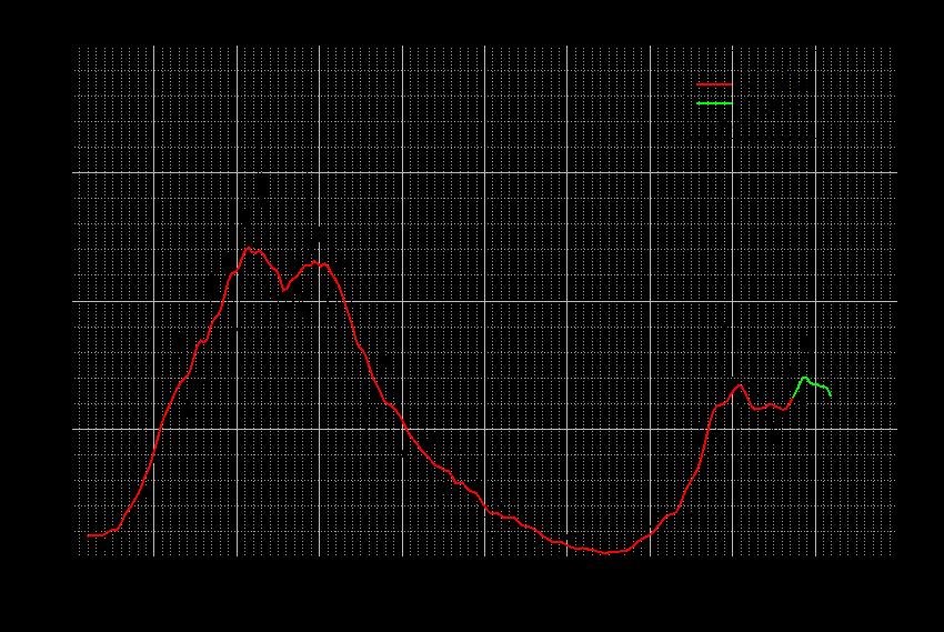


10 Solar Activity Recent Solar Activity
, some layers absorb")
11 Ionosphere Sun ionizes atmosphere during daytime Layers dissipate and combine at night Some layers reflect (E, F), some layers absorb (D)
: no reflection")

12 Usable Frequencies Lowest usable frequency (LUF): absorption Maximum usable frequency (MUF): no reflection Web sites calculate these for you for any day or time Frequency Too Low Absorbed Frequency Too High Not Reflected Earth

13

14 10 m, 28 MHz : Day

15 20 m, 14 MHz : Grayline

16 40 m, 7 MHz : Night

17 The World Seen From California!
18 Other Radio Reflectors Meteor trails Aurora Satellites Moon


19 Aurora Aurora is due to charged particles from the sun following the earth s magnetic field lines These reflect radio waves over thousands of miles
20 Antennas
21 Antenna Couples amplifier to propagating waves Currents on the antenna elements produce electric and magnetic fields in space Antenna dimensions matched to dimensions of the electromagnetic wave you want to generate
22 Types of Antennas Omni-directional: no direction preference Directional beam: Focuses energy in one direction Gain: How much the signal is enhanced in one direction, compared to a reference antenna. Measured in db, i.e. 10 log10 (P/Pr) dbi : compared to an ideal isotropic antenna dbd : compared to a dipole antenna
23 Radiation Patterns
24 Current in a Conductor Current flows along conductor Electric fields parallel Magnetic fields perpendicular E(t) i(t) H(t)
25 Dipole Antenna Drive the antenna at center, offset Sets the input impedance Shield Center Coax Cable
26 Dipole Antenna Sinusoidal input sets up half cycle of current along antenna Length should be 1/2 wavelength for the frequency i(t,x) Shield Center Coax Cable Input, s(t)
27 Dipole Antenna Oscillating electric field propagates away from antenna Propagation Direction Shield Electric Field Center Coax Cable Input, s(t)
28 Dipole Antenna Length is 1/2 wavelength of the transmit carrier frequency For 150 MHz one wavelength is 2 m, and the antenna should be 1 m long For 450 MHz, one wavelength is 67 cm, and the antenna should be 33 cm long
29 Dipole Radiation Pattern Horizontal Horizontal Vertical
30 Polarization Polarization is the direction of the electric field (horizontal, vertical, circular) A horizontal dipole has a horizontal polarization A vertical dipole has a vertical polarization If the transmitting and receiving antennas have different polarizations, there can be a very large signal loss
31 1/4 Wave Vertical Antennas Conducting surfaces (the earth, your car roof) act as current mirrors Conducting Plane Conducting Plane You get the second half of the antenna for free! Antenna above Conducting Plane Effective Antenna
32 1/4 Wave Antennas
33 Beam Antennas Yagi Delta Quad Generally one driven element Directors to focus energy forward Reflectors to cancel out pattern to the rear
34 Feed Lines Balun Duplexer Antenna switch SWR meter Antenna analyzer Antenna tuner
35 Types of Coax RG-58 : most common RG-8 : low loss, large RG-8x : between RG-58 and RG-8 in size and loss RG-213 : low loss, large RG-174: micro coax, high loss Hardline : very low loss
36 Coax Most common feed lines Commonly 50 Ohm impedance (there are others) Loss depends on frequency (in db/100 ft)
37 Coax Cable Loss Type Impedance 30 MHz (db/100ft) MHz (db/100ft) RG RG RG RG

38 Connectors SO-259, UHF Common for HF Up to 450 MHz N Common above 400 MHz BNC up to GHz SMA GHz and above

39 Connectors
40 Connection to the Antenna Ideally, all the power from the feed line ends up in the antenna The feed line impedance and the antenna input impedance should be matched If the impedances are mismatched, some of the power is reflected back to the amplifier Reduces transmit power Increases line losses Reduces amplifier output, can damage the amplifier
41 Standing Wave Ratio (SWR) Ratio of total to forward power Always in the for X:1, where X is greater than 1 Perfect SWR is 1:1 Semiconductor amps begin have trouble at SWR of 2:1
42 Antenna Matching Matching Network : built into the antenna Antenna Tuner : adjustable matching network Doesn t really tune the antenna Antenna Analyzer : measures the antenna input impedance, frequency response SWR Meter : measures SWR Directional Watt Meter : measures power in one direction, can be used to compute SWR


43 SWR / Directional Wattmeter Antenna Analyzer Antenna Tuner
Antennas and Propagation Chapters T4, G7, G8 Antenna Fundamentals, More Antenna Types, Feed lines and Measurements, Propagation
 Antennas and Propagation Chapters T4, G7, G8 Antenna Fundamentals, More Antenna Types, Feed lines and Measurements, Propagation =============================================================== Antenna Fundamentals
FCC Technician License Course
 FCC Technician License Course 2014-2018 FCC Element 2 Technician Class Question Pool Presented by: Tamiami Amateur Radio Club (TARC) WELCOME To the third of 4, 3-hour classes presented by TARC to prepare
Technician License Course Chapter 4
 Technician License Course Chapter 4 Propagation, Basic Antennas, Feed lines & SWR K0NK 26 Jan 18 The Antenna System Antenna: Facilitates the sending of your signal to some distant station. Feed line: Connects
Technician Licensing Class T9
 Technician Licensing Class T9 Amateur Radio Course Monroe EMS Building Monroe, Utah January 11/18, 2014 January 22, 2014 Testing Session Valid dates: July 1, 2010 June 30, 2014 Amateur Radio Technician
4/25/2012. Supplement T9. 2 Exam Questions, 2 Groups. Amateur Radio Technician Class T9A: T9A: T9A: T9A:
 Amateur Radio Technician Class Element 2 Course Presentation ti ELEMENT 2 SUB-ELEMENTS Technician Licensing Class Supplement T9 Antennas, Feedlines 2 Exam Questions, 2 Groups T1 - FCC Rules, descriptions
Lesson 12: Signal Propagation
 Lesson 12: Signal Propagation Preparation for Amateur Radio Technician Class Exam Topics HF Propagation Ground-wave Sky-wave Ionospheric regions VHF/UHF Propagation Line-of-sight Tropospheric Bending and
Technician License. Course
 Technician License Course Technician License Course Chapter 4 Lesson Plan Module - 9 Antenna Fundamentals Feed Lines & SWR The Antenna System The Antenna System Antenna: Transforms current into radio waves
Technician License Course Chapter 4. Lesson Plan Module 9 Antenna Fundamentals, Feed Lines & SWR
 Technician License Course Chapter 4 Lesson Plan Module 9 Antenna Fundamentals, Feed Lines & SWR The Antenna System Antenna: Transforms current into radio waves (transmit) and vice versa (receive). Feed
Chapter 15: Radio-Wave Propagation
 Chapter 15: Radio-Wave Propagation MULTIPLE CHOICE 1. Radio waves were first predicted mathematically by: a. Armstrong c. Maxwell b. Hertz d. Marconi 2. Radio waves were first demonstrated experimentally
Chapter 4. Propagation, Antennas and Feed Lines. Propagation Black magic topic #1. How do radio waves get from point A to point B?
 Chapter 4 Propagation, Antennas and Feed Lines Propagation Black magic topic #1. How do radio waves get from point A to point B? 1 Radio Wave Propagation Normally radio waves travel in a straight line,
Chapter 6 Antenna Basics. Dipoles, Ground-planes, and Wires Directional Antennas Feed Lines
 Chapter 6 Antenna Basics Dipoles, Ground-planes, and Wires Directional Antennas Feed Lines Some General Rules Bigger is better. (Most of the time) Higher is better. (Most of the time) Lower SWR is better.
Technician License. Course
 Technician License Course Technician License Course Chapter 4 Lesson Plan Module - 10 Practical Antennas The Dipole Most basic antenna The Dipole Most basic antenna The Dipole Total length is ½ wavelength
SCARS Technician / General License Course Week 4
 SCARS Technician / General License Course Week 4 Radio Wave Propagation: Getting from Point A to Point B Radio waves propagatein many ways depending on Frequency of the wave Characteristics of the environment
Technician Licensing Class. Antennas
 Technician Licensing Class Antennas Antennas A simple dipole mounted so the conductor is parallel to the Earth's surface is a horizontally polarized antenna. T9A3 Polarization is referenced to the Earth
Milton Keynes Amateur Radio Society (MKARS)
") Milton Keynes Amateur Radio Society (MKARS) Intermediate Licence Course Feeders Antennas Matching (Worksheets 31, 32 & 33) MKARS Intermediate Licence Course - Worksheet 31 32 33 Antennas Feeders Matching
Milton Keynes Amateur Radio Society (MKARS) Intermediate Licence Course Feeders Antennas Matching (Worksheets 31, 32 & 33) MKARS Intermediate Licence Course - Worksheet 31 32 33 Antennas Feeders Matching
CHAPTER 8 ANTENNAS 1
 CHAPTER 8 ANTENNAS 1 2 Antennas A good antenna works A bad antenna is a waste of time & money Antenna systems can be very inexpensive and simple They can also be very expensive 3 Antenna Considerations
3 Methods of radiocommunication
 + + & & * * ) ) From the ITU Emergency Telecommunications handbook; prepared for the 54 th JOTA 2011. 3 Methods of radiocommunication 3.1 Frequencies Radio frequencies should be selected according to propagation
Antennas Demystified Antennas in Emergency Communications. Scott Honaker N7SS
 Antennas Demystified Antennas in Emergency Communications Scott Honaker N7SS Importance of Antennas Antennas are more important than the radio A $5000 TV with rabbit ears will have a lousy picture Antennas
4/18/2012. Supplement T3. 3 Exam Questions, 3 Groups. Amateur Radio Technician Class
 Amateur Radio Technician Class Element 2 Course Presentation ti ELEMENT 2 SUB-ELEMENTS Technician Licensing Class Supplement T3 Radio Wave Characteristics 3 Exam Questions, 3 Groups T1 - FCC Rules, descriptions
4/29/2012. General Class Element 3 Course Presentation. Ant Antennas as. Subelement G9. 4 Exam Questions, 4 Groups
 General Class Element 3 Course Presentation ti ELEMENT 3 SUB ELEMENTS General Licensing Class Subelement G9 Antennas and Feedlines 4 Exam Questions, 4 Groups G1 Commission s Rules G2 Operating Procedures
Sw earth Dw Direct wave GRw Ground reflected wave Sw Surface wave
 WAVE PROPAGATION By Marcel H. De Canck, ON5AU Electromagnetic radio waves can propagate in three different ways between the transmitter and the receiver. 1- Ground waves 2- Troposphere waves 3- Sky waves
VHF/UHF Beyond FM Bob Witte KØNR Page 1
 VHF/UHF Beyond FM Technical Coordinator Colorado Section Page 1 Objective The objective of this presentation is to provide an introduction to operating on VHF/UHF, going beyond the usual FM / Repeater
4/29/2012. General Class Element 3 Course Presentation. Radio Wave Propagation. Radio Wave Propagation. Radio Wave Propagation.
 General Class Element 3 Course Presentation ti ELEMENT 3 SUB ELEMENTS General Licensing Class Subelement G3 3 Exam Questions, 3 Groups G1 Commission s Rules G2 Operating Procedures G3 G4 Amateur Radio
Amateur Radio Service Technician Class
 Amateur Radio Service Technician Class Exam Preparation Class January 2019 Session 2 Roland K. Smith K7OJL Phone: (435) 849-1946 Email: rolandksmith@gmail.com 1 TechClass-Session2.key - January 11, 2019
Chapter 6 Propagation
 Chapter 6 Propagation Al Penney VO1NO Objectives To become familiar with: Classification of waves wrt propagation; Factors that affect radio wave propagation; and Propagation characteristics of Amateur
General Class License Theory III. Dick Grote K6PBF
 General Class License Theory III Dick Grote K6PBF K6pbfdick@gmail.com 1 Introduction In this session we will learn about: Feed Lines Antennas Safety As in the other theory classes, we will try to present
Polarization orientation of the electric field vector with respect to the earth s surface (ground).
.") Free space propagation of electromagnetic waves is often called radio-frequency (rf) propagation or simply radio propagation. The earth s atmosphere, as medium introduces losses and impairments to the
Free space propagation of electromagnetic waves is often called radio-frequency (rf) propagation or simply radio propagation. The earth s atmosphere, as medium introduces losses and impairments to the
Technician Licensing Class. Lesson 4. presented by the Arlington Radio Public Service Club Arlington County, Virginia
 Technician Licensing Class Lesson 4 presented by the Arlington Radio Public Service Club Arlington County, Virginia 1 Quiz Sub elements T6 & T7 2 Good Engineering Practice Sub element T8 3 A Basic Station
Colubris Networks. Antenna Guide
 Colubris Networks Antenna Guide Creation Date: February 10, 2006 Revision: 1.0 Table of Contents 1. INTRODUCTION... 3 2. ANTENNA TYPES... 3 2.1. OMNI-DIRECTIONAL ANTENNA... 3 2.2. DIRECTIONAL ANTENNA...
The A-B-C's of Radio Waves and Antennas
 The A-B-C's of Radio Waves and Antennas By Greg S. Carpenter GregsBasicElectronics.com What is the most important thing in common with both the transmitter and receiver? It's the antenna and without a
RF Propagation. By Tim Kuhlman, PE KD7RUS
 RF Propagation By Tim Kuhlman, PE KD7RUS Purpose of this Seminar In this seminar we will attempt to answer the following questions: What is RF propagation? What are the different types of propagation?
RF Propagation. By Tim Kuhlman, PE KD7RUS
 RF Propagation By Tim Kuhlman, PE KD7RUS Purpose of this Seminar In this seminar we will attempt to answer the following questions: What is RF propagation? What are the different types of propagation?
Chapter 7 HF Propagation. Ionosphere Solar Effects Scatter and NVIS
 Chapter 7 HF Propagation Ionosphere Solar Effects Scatter and NVIS Ionosphere and Layers Radio Waves Bent by the Ionosphere Daily variation of Ionosphere Layers Ionospheric Reflection Conduction by electrons
Technician License Course Chapter 2 Radio and Electronics Fundamentals. PHYS 401 Spring 2009 P. Reiff, Rice University
 Technician License Course Chapter 2 Radio and Electronics Fundamentals PHYS 401 Spring 2009 P. Reiff, Rice University Basic Station Organization Station Equipment Receiver Transmitter Antenna Power Supply
UNIT Derive the fundamental equation for free space propagation?
 UNIT 8 1. Derive the fundamental equation for free space propagation? Fundamental Equation for Free Space Propagation Consider the transmitter power (P t ) radiated uniformly in all the directions (isotropic),
Antennas and Propagation. Prelude to Chapter 4 Propagation
 Antennas and Propagation Prelude to Chapter 4 Propagation Introduction An antenna is an electrical conductor or system of conductors for: Transmission - radiates electromagnetic energy into space (involves
This Antenna Basics reference guide includes basic information about antenna types, how antennas work, gain, and some installation examples.
 Antenna Basics This Antenna Basics reference guide includes basic information about antenna types, how antennas work, gain, and some installation examples. What Do Antennas Do? Antennas transmit radio
Technician License Course Chapter 4. Lesson Plan Module 10 Practical Antennas
 Technician License Course Chapter 4 Lesson Plan Module 10 Practical Antennas The Dipole Most basic antenna Total length is ½ wavelength (½ λ) Usual construction: Two equal halves of wire, rod, or tubing
BHARATHIDASAN ENGINEERING COLLEGE NATTARAMPALLI Frequently Asked Questions (FAQ) Unit 1
 Unit 1") BHARATHIDASAN ENGINEERING COLLEGE NATTARAMPALLI 635854 Frequently Asked Questions (FAQ) Unit 1 Degree / Branch : B.E / ECE Sem / Year : 3 rd / 6 th Sub Name : Antennas & Wave Propagation Sub Code : EC6602
BHARATHIDASAN ENGINEERING COLLEGE NATTARAMPALLI 635854 Frequently Asked Questions (FAQ) Unit 1 Degree / Branch : B.E / ECE Sem / Year : 3 rd / 6 th Sub Name : Antennas & Wave Propagation Sub Code : EC6602
General License Class Chapter 6 - Antennas. Bob KA9BHD Eric K9VIC
 General License Class Chapter 6 - Antennas Bob KA9BHD Eric K9VIC Learning Objectives Teach you enough to get all the antenna questions right during the VE Session Learn a few things from you about antennas
Topics in Propagation
 Topics in Propagation Extra Class Course Spring 2013 Andy Durbin k3wyc Propagation The magic that allows a signal to travel between the transmitting antenna and the receiving antenna. This course is limited
Least understood topics by most HAMs RF Safety Ground Antennas Matching & Feed Lines
 Least understood topics by most HAMs RF Safety Ground Antennas Matching & Feed Lines Remember this question from the General License Exam? G0A03 (D) How can you determine that your station complies with
4 Antennas as an essential part of any radio station
 4 Antennas as an essential part of any radio station 4.1 Choosing an antenna Communicators quickly learn two antenna truths: Any antenna is better than no antenna. Time, effort and money invested in the
Definitions of Technical Terms
 Definitions of Technical Terms Terms Ammeter Amperes, Amps Band Capacitor Carrier Squelch Diode Dipole Definitions How is an ammeter usually connected = In series with the circuit What instrument is used
Intermediate Course (5) Antennas and Feeders
 Antennas and Feeders") Intermediate Course (5) Antennas and Feeders 1 System Transmitter 50 Ohms Output Standing Wave Ratio Meter Antenna Matching Unit Feeder Antenna Receiver 2 Feeders Feeder types: Coaxial, Twin Conductors
Intermediate Course (5) Antennas and Feeders 1 System Transmitter 50 Ohms Output Standing Wave Ratio Meter Antenna Matching Unit Feeder Antenna Receiver 2 Feeders Feeder types: Coaxial, Twin Conductors
Antennas 101 Don t Be a 0.97 db Weakling! Ward Silver NØAX
 Antennas 101 Don t Be a 0.97 db Weakling! Ward Silver NØAX Overview Antennas 101 2 Overview Basic Antennas: Ground Plane / Dipole How Gain and Nulls are Formed How Phased Arrays Work How Yagis Work (simplified)
Practical Antennas and. Tuesday, March 4, 14
 Practical Antennas and Transmission Lines Goals Antennas are the interface between guided waves (from a cable) and unguided waves (in space). To understand the various properties of antennas, so as to
AN INTRODUCTION TO VHF/ UHF PROPAGATION. Paul Wilton, M1CNK
 AN INTRODUCTION TO VHF/ UHF PROPAGATION Paul Wilton, M1CNK OVERVIEW Introduction Propagation Basics Propagation Modes Getting Started in 2m DX INTRODUCTION QRV on 2m SSB since Aug 1998, on 6m since Jan
right during the VE Session Have fun Bob, KA9BH Eric, K9VIC
 Radio Wave Propagation Teach you enough to get all right during the VE Session Learn a few things from you Have fun Finish everything on time (if the propagation questions about your experiences not a
Chapter 5.0 Antennas Section 5.1 Theory & Principles
 Chapter 5.0 Antennas Section 5.1 Theory & Principles G3C11 (B) p.135 Which of the following antenna types will be most effective for skip communications on 40-meters during the day? A. A vertical antenna
ANTENNA THEORY WAVE PROPAGATION HF ANTENNAS
 ANTENNA THEORY WAVE PROPAGATION & HF ANTENNAS FREQUENCY SPECTRUM INFORMATION Frequency range American designator below 300 Hz..ELF (extremely Low Frequency) 300-3000 Hz..ILF (Intermediate Low Frequency)
Basic Radio Physics. Developed by Sebastian Buettrich. ItrainOnline MMTK 1
 Basic Radio Physics Developed by Sebastian Buettrich 1 Goals Understand radiation/waves used in wireless networking. Understand some basic principles of their behaviour. Apply this understanding to real
6 Radio and RF. 6.1 Introduction. Wavelength (m) Frequency (Hz) Unit 6: RF and Antennas 1. Radio waves. X-rays. Microwaves. Light
 Frequency (Hz) Unit 6: RF and Antennas 1. Radio waves. X-rays. Microwaves. Light") 6 Radio and RF Ref: http://www.asecuritysite.com/wireless/wireless06 6.1 Introduction The electromagnetic (EM) spectrum contains a wide range of electromagnetic waves, from radio waves up to X-rays (as
6 Radio and RF Ref: http://www.asecuritysite.com/wireless/wireless06 6.1 Introduction The electromagnetic (EM) spectrum contains a wide range of electromagnetic waves, from radio waves up to X-rays (as
Chapter 13: Wave Propagation. EET-223: RF Communication Circuits Walter Lara
 Chapter 13: Wave Propagation EET-223: RF Communication Circuits Walter Lara Electrical to Electromagnetic Conversion Since the atmosphere is not a conductor of electrons (instead a good insulator), electrical
Antennas and Propagation
 Antennas and Propagation Chapter 5 Introduction An antenna is an electrical conductor or system of conductors Transmission - radiates electromagnetic energy into space Reception - collects electromagnetic
Session2 Antennas and Propagation
 Wireless Communication Presented by Dr. Mahmoud Daneshvar Session2 Antennas and Propagation 1. Introduction Types of Anttenas Free space Propagation 2. Propagation modes 3. Transmission Problems 4. Fading
Antennas and Propagation
 CMPE 477 Wireless and Mobile Networks Lecture 3: Antennas and Propagation Antennas Propagation Modes Line of Sight Transmission Fading in the Mobile Environment Introduction An antenna is an electrical
Data and Computer Communications. Tenth Edition by William Stallings
 Data and Computer Communications Tenth Edition by William Stallings Data and Computer Communications, Tenth Edition by William Stallings, (c) Pearson Education - Prentice Hall, 2013 Wireless Transmission
Space Weather and Propagation JANUARY 14, 2017
 Space Weather and Propagation MARTIN BUEHRING -KB4MG ELEC T R ICAL ENGINEER, A M AT EUR EXTRA CLASS LICENSE HOLDER JANUARY 14, 2017 Why know about Space Weather? Our SUN has an enormous affect not only
Lesson 11: Antennas. Copyright Winters Version 1.0. Preparation for Amateur Radio Technician Class Exam
 Lesson 11: Antennas Preparation for Amateur Radio Technician Class Exam Topics Antenna ½ wave Dipole antenna ¼ wave Vertical antenna Antenna polarization Antenna location Beam antennas Test Equipment Exam
OBJECTIVES: PROPAGATION INTRO RADIO WAVES POLARIZATION LINE OF SIGHT, GROUND WAVE, SKY WAVE IONOSPHERE REGIONS PROPAGATION, HOPS, SKIPS ZONES THE
 WAVE PROPAGATION OBJECTIVES: PROPAGATION INTRO RADIO WAVES POLARIZATION LINE OF SIGHT, GROUND WAVE, SKY WAVE IONOSPHERE REGIONS PROPAGATION, HOPS, SKIPS ZONES THE IONOSPHERIC LAYERS ABSORPTION AND FADING
Project = An Adventure : Wireless Networks. Lecture 4: More Physical Layer. What is an Antenna? Outline. Page 1
 Project = An Adventure 18-759: Wireless Networks Checkpoint 2 Checkpoint 1 Lecture 4: More Physical Layer You are here Done! Peter Steenkiste Departments of Computer Science and Electrical and Computer
Antennas and Propagation. Chapter 5
 Antennas and Propagation Chapter 5 Introduction An antenna is an electrical conductor or system of conductors Transmission - radiates electromagnetic energy into space Reception - collects electromagnetic
Radio Communication. Presentation created by: András Balogh
 Radio Communication Presentation created by: András Balogh AM and FM The goal is to transmit a modulating signal S(t) via a wave sin(ωt). In case of AM, the product of the modulation is f(t)=(a+s(t))*sin(ωt);
Antenna Fundamentals
 HTEL 104 Antenna Fundamentals The antenna is the essential link between free space and the transmitter or receiver. As such, it plays an essential part in determining the characteristics of the complete
Reading 28 PROPAGATION THE IONOSPHERE
 Reading 28 Ron Bertrand VK2DQ http://www.radioelectronicschool.com PROPAGATION THE IONOSPHERE The ionosphere is a region of the upper atmosphere extending from a height of about 60 km to greater than 500
# DEFINITIONS TERMS. 2) Electrical energy that has escaped into free space. Electromagnetic wave
 Electrical energy that has escaped into free space. Electromagnetic wave") CHAPTER 14 ELECTROMAGNETIC WAVE PROPAGATION # DEFINITIONS TERMS 1) Propagation of electromagnetic waves often called radio-frequency (RF) propagation or simply radio propagation. Free-space 2) Electrical
CHAPTER 14 ELECTROMAGNETIC WAVE PROPAGATION # DEFINITIONS TERMS 1) Propagation of electromagnetic waves often called radio-frequency (RF) propagation or simply radio propagation. Free-space 2) Electrical
Chapter-15. Communication systems -1 mark Questions
 Chapter-15 Communication systems -1 mark Questions 1) What are the three main units of a Communication System? 2) What is meant by Bandwidth of transmission? 3) What is a transducer? Give an example. 4)
ANTENNAS. I will mostly be talking about transmission. Keep in mind though, whatever is said about transmission is true of reception.
 Reading 37 Ron Bertrand VK2DQ http://www.radioelectronicschool.com ANTENNAS The purpose of an antenna is to receive and/or transmit electromagnetic radiation. When the antenna is not connected directly
Chapter 4 The RF Link
 Chapter 4 The RF Link The fundamental elements of the communications satellite Radio Frequency (RF) or free space link are introduced. Basic transmission parameters, such as Antenna gain, Beamwidth, Free-space
Antenna Basics. Antennas. A guide to effective antenna use
 A guide to effective antenna use Antennas Antennas transmit radio signals by converting radio frequency electrical currents into electromagnetic waves. Antennas receive the signals by converting the electromagnetic
Antennas and Propagation. Chapter 5
 Antennas and Propagation Chapter 5 Introduction An antenna is an electrical conductor or system of conductors Transmission - radiates electromagnetic energy into space Reception - collects electromagnetic
Radio Propagation Fundamentals
 Radio Propagation Fundamentals Concept of Electromagnetic Wave Propagation Mechanisms Modes of Propagation Propagation Models Path Profiles Link Budget Fading Channels Electromagnetic (EM) Waves EM Wave
Half-Wave Dipole. Radiation Resistance. Antenna Efficiency
 Antennas Simple Antennas Isotropic radiator is the simplest antenna mathematically Radiates all the power supplied to it, equally in all directions Theoretical only, can t be built Useful as a reference:
D. Frequency. C. 1,500 milliamperes. A khz. C. One thousand volts T5A12
 T5A12 What term describes the number of times per second that an alternating current reverses direction? A. Pulse rate B. Speed C. Wavelength D. Frequency T5A12 D. Frequency ARRL Tech Manual: Page 2-1
RADIO WAVE PROPAGATION
 CHAPTER 2 RADIO WAVE PROPAGATION Radio direction finding (RDF) deals with the direction of arrival of radio waves. Therefore, it is necessary to understand the basic principles involved in the propagation
Back to the Basics Setting up a VHF/UHF Station
 Back to the Basics Setting up a VHF/UHF Station Back to The Basics Your First VHF/UHF Station Topics that will be covered: Radios l Base/mobile vs. Hand Held l Pluses and minuses of each l Antennas l Vertical
General Classs Chapter 7
 General Classs Chapter 7 Radio Wave Propagation Bob KA9BHD Eric K9VIC Learning Objectives Teach you enough to get all the propagation questions right during the VE Session Learn a few things from you about
Antenna. Wave length Km/s
 Antenna 5% Wave length 300 000 Km/s 066 velocity factor RG-58 = C = = F : 120 Impedance 50 50 50 VSWR and Reflected Power SWR VSWR VSWR 2:1 Voltage Standing Wave Ratio VSWR 15:1 15:1 VSWR 100 Watt 1:1
Maximum Usable Frequency
 Maximum Usable Frequency 15 Frequency (MHz) 10 5 0 Maximum Usable Frequency Usable Frequency Window Lowest Usable Frequency Solar Flare 6 12 18 24 Time (Hours) Radio Blackout Usable Frequency Window Ken
Chapter 9 Antennas and Feedlines
 Chapter 9 Antennas and Feedlines Basics of Antennas Antenna Radiation Patterns. Graphical representation of spatial distribution of energy around an antenna. 3D = Full representation. 2D = Slice through
UNDER STANDING RADIO FREQUENCY Badger Meter, Inc.
 UNDER STANDING RADIO FREQUENCY UNDERSTANDING RADIO FREQUENCY Regional Sales Meeting March 1-2, 2011 Brian Fiut Sr. Product Manager Itron Inc. Liberty Lake, WA August 25, 2010 RADIO PROPAGATION Radio consists
INTRODUCTION TO RF PROPAGATION
 INTRODUCTION TO RF PROPAGATION John S. Seybold, Ph.D.,WILEY- 'interscience JOHN WILEY & SONS, INC. Preface XIII 1. Introduction 1.1 Frequency Designations 1 1.2 Modes of Propagation 3 1.2.1 Line-of-Sight
INSTITUTE OF AERONAUTICAL ENGINEERING Dundigal, Hyderabad ELECTRONICS AND COMMUNIACTION ENGINEERING QUESTION BANK
 INSTITUTE OF AERONAUTICAL ENGINEERING Dundigal, Hyderabad - 500 04 ELECTRONICS AND COMMUNIACTION ENGINEERING QUESTION BANK Course Name : Antennas and Wave Propagation (AWP) Course Code : A50418 Class :
S.R.M. Institute of Science & Technology Deemed University School of Electronics & Communication Engineering
 S.R.M. Institute of Science & Technology Deemed University School of Electronics & Communication Engineering Question Bank Subject Code : EC401 Subject Name : Antennas and Wave Propagation Year & Sem :
Antennas and Propagation
 Mobile Networks Module D-1 Antennas and Propagation 1. Introduction 2. Propagation modes 3. Line-of-sight transmission 4. Fading Slides adapted from Stallings, Wireless Communications & Networks, Second
"Natural" Antennas. Mr. Robert Marcus, PE, NCE Dr. Bruce C. Gabrielson, NCE. Security Engineering Services, Inc. PO Box 550 Chesapeake Beach, MD 20732
 Published and presented: AFCEA TEMPEST Training Course, Burke, VA, 1992 Introduction "Natural" Antennas Mr. Robert Marcus, PE, NCE Dr. Bruce C. Gabrielson, NCE Security Engineering Services, Inc. PO Box
CHAPTER 6. Propagation
 CHAPTER 6 Propagation TOC: INTRO RADIO WAVES POLARIZATION LINE OF SIGHT, GROUND & SKY WAVES IONOSPHERE REGIONS IONOSPHERIC LAYERS PROPAGATION, HOPS, SKIPS ZONES ABSORPTION AND FADING SOLAR ACTIVITY AND
Antenna? What s That? Chet Thayer WA3I
 Antenna? What s That? Chet Thayer WA3I Space: The Final Frontier Empty Space (-Time) Four dimensional region that holds everything Is Permeable : It requires energy to set up a magnetic field within it.
Range Considerations for RF Networks
 TI Technology Days 2010 Range Considerations for RF Networks Richard Wallace Abstract The antenna can be one of the most daunting components of wireless designs. Most information available relates to large
UNIT V PROPAGATION The three basic types of propagation: Sky Wave Propagation: Space Wave Propagation: Ground Wave Propagation: Propagation of Waves
 UNIT V PROPAGATION The three basic types of propagation: Ground wave, space wave and sky wave propagation. Sky Wave Propagation: Structure of the ionosphere Effective dielectric constant of ionized region
Technical Note: Path Align-R Wireless Supporting Information
 Technical Note: Path Align-R Wireless Supporting Information Free-space Loss The Friis free-space propagation equation is commonly used to determine the attenuation of a signal due to spreading of the
Structure of the Lecture
 Structure of the Lecture Chapter 2 Technical Basics: Layer 1 Methods for Medium Access: Layer 2 Representation of digital signals on an analogous medium Signal propagation Characteristics of antennas Chapter
COAXIAL TRANSMISSION LINE COMMON-MODE CURRENT
 COAXIAL TRANSMISSION LINE COMMON-MODE CURRENT Introduction Coaxial transmission lines are popular for their wide frequency bandwidth and high resistance to electromagnetic interference (EMI). Coax cables
Data and Computer Communications Chapter 4 Transmission Media
 Data and Computer Communications Chapter 4 Transmission Media Ninth Edition by William Stallings Data and Computer Communications, Ninth Edition by William Stallings, (c) Pearson Education - Prentice Hall,
Basic radio physics. Sebastian Büttrich, NSRC/ITU/wire.less.dk edit: June
 Basic radio physics Sebastian Büttrich, NSRC/ITU/wire.less.dk edit: June 2011 http://creativecommons.org/licenses/by-nc-sa/3.0/ Electromagnetic Fields Electromagnetic forces act between electric charges
Chapter 1 Introduction
 Wireless Information Transmission System Lab. Chapter 1 Introduction National Sun Yat-sen University Table of Contents Elements of a Digital Communication System Communication Channels and Their Wire-line
Antennas & Propagation. CSG 250 Fall 2007 Rajmohan Rajaraman
 Antennas & Propagation CSG 250 Fall 2007 Rajmohan Rajaraman Introduction An antenna is an electrical conductor or system of conductors o Transmission - radiates electromagnetic energy into space o Reception
3C5 Telecommunications. what do radios look like? mobile phones. Linda Doyle CTVR The Telecommunications Research Centre
 3C5 Telecommunications what do radios look like? Linda Doyle CTVR The Telecommunications Research Centre ledoyle@tcd.ie Oriel/Dunlop House 2009 mobile phones talk is cheap.. bluetooth 3G WLAN/802.11 GSM
Satellite Signals and Communications Principles. Dr. Ugur GUVEN Aerospace Engineer (P.hD)
") Satellite Signals and Communications Principles Dr. Ugur GUVEN Aerospace Engineer (P.hD) Principle of Satellite Signals In essence, satellite signals are electromagnetic waves that travel from the satellite
Satellite Signals and Communications Principles Dr. Ugur GUVEN Aerospace Engineer (P.hD) Principle of Satellite Signals In essence, satellite signals are electromagnetic waves that travel from the satellite