db = 10 log10 (P1/P2) where P1 and P2 are two power levels
|
|
|
- Roxanne Carr
- 6 years ago
- Views:
Transcription
1 A Quick Introduction to Decibels (db) Unit is the Bel: named after A.G. Bell who devised it for his work with deafness and audio sound levels. Now used for all frequencies of AC power. Decibel (db): -1 db = 1/10 (0.1) Bel -roughly smallest change in sound power the human ear can hear -ear, eye have a logarithmic response to sound, light -db is a logarithmic unit -db is always a comparison to a reference value db = 10 log10 (P1/P2) where P1 and P2 are two power levels being compared Voltage or current levels can also be compared using db, but for our purposes and most radio work power levels will be assumed. Voltage equation: db= 20 log10 (V1/V2)
2 Practical power gain or loss relationships in db. Reference = 1.0 Wat Power compared to 1.0 W expressed as db 1.0 W (1kW) ,000 (10 kw) ,000 (20 kw) W (10 mw) (1mW) (100 μw) (50 μw) -43
 Balanced Coaxial de Fred Archibald VE1FA hfarchibald@ns.sympatico.")
3 Halifax Amateur Radio Club Basic Course Transmission Lines (Chapter 7) Balanced Coaxial de Fred Archibald VE1FA
4 Ideal transmission line: 1. No losses 2. No radiation (TX)/no reception (RX) 3. Constant characteristics
 Practical result: TX/RX Zout should match trans.")
5 Every transmission line has a characteristic impedance (Z0), measured in ohms (Ω) Z0 = complex sum of line s R + XL + XC Z0 :determined by spacing, thickness of wires, and dielectric between Z0: if used to terminate the line, will give an SWR of 1:1 and maximum power transfer distributed R + L + C (equivalent circuit) Practical result: TX/RX Zout should match trans. line Z0, which should match antenna Z Common trans. line Z: 50, 72, 300, 450, 600 Ω 50Ω co-ax: all amateur and most commercial radios 72Ω co-ax: most TV/video cellular phone radios
6 (V)SWR: (Voltage) Standing Wave Ratio VSWR = VF + VR/VF - VR A measure of Z mismatch or reflected RF power If Z0 = 50Ω and ZANT = 50Ω SWR = 1:1.0 ZANT = 100Ω SWR = 1:2.0 ZANT = 25Ω SWR = 1:2.0 ZANT = 12.5Ω SWR = 1:4.0 ZANT = 500Ω SWR = 1:10 Perfect! (efficient Z match) Very poor (inefficient Z match)


7 Antenna tuner: matches Z of transmission line + antenna to transmiter It DOES NOT tune the antenna! Often power/swr meter, dummy load, balun, and antenna switch in tuner
8 Common tuner circuits: the larger the values of C + L, the greater frequency and impedance matching ranges < or > 50Ω High-pass T tuner <50Ω High-pass L tuner >50Ω High-pass L tuner Ant. Z >50Ω Low-pass L tuner Will an internal transceiver auto-tuner replace a separate tuner??
9 Typical modern antenna tuner (radio to co-ax impedance (Z) matcher) Features included: RF power and SWR meters (M) Wide-match, high-pass T type tuner (CTX, L, CANT) Antenna selector switch (S2) Balun (4:1) for balanced transmission line (BAL) Resistive dummy load for testing and tuning (DL) M DL A1-4 = antenna choices S1 = tuner-bypass-dummy load switch
10 Loop HB Tuner Settings* rev. Oct. 28, 2004 Ant. Tuner preset sheet -allows fast tune-up with litle or no on-air tuning (QRM) -unique values for every station and antenna -you will make up your own -6m and above: tuners rarely used L Tx Band Freq. C C (meters) 10 m (MHz) m m m m m m m m m all with 550' loop, 60' ladder line, 4:1 current balun into T- tuner.

11 2017 Kenwood TS-590SG HF transceiver power/swr display

12 Analog power and SWR (standing wave ratio) meter for MHz. Has 3 ranges: 0-20, and W of RF power Point where needles cross gives the SWR. Power readout is only accurate when SWR is LOW!


13 Transceiver internal auto-tuners Analog-mechanical design Remote weatherproof tuner Great for high efficiency on the tower Z matching Digital fixed C+L values design
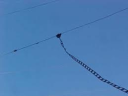
14 Balanced Transmission Lines -2 parallel wires, unshielded -signals 180 out-of phase Z0 = 276 log10 x 2(S/d) S = distance between 2 wires d = diameter of 2 wires Advantages -very low losses -takes high voltage, power, SWR -cheap Disadvantages -influenced by nearby metal -ant. tuner must be balanced or have balun -flaps/fatigues in wind
15 How a balanced transmission line rejects noise (and is prevented from being an antenna)!

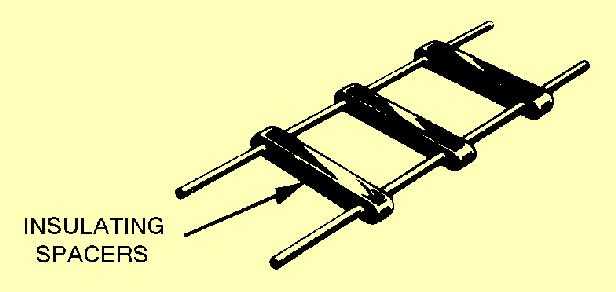
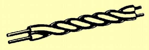
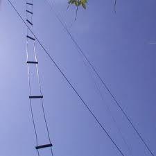
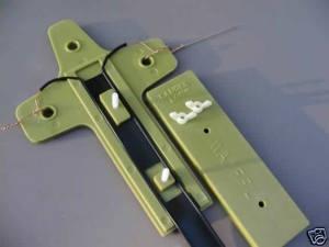
16 Balanced Feedline Types

17
 Unbalanced")
18 Balun (Balanced: Unbalanced) transformers) Balanced line (ferrite doughnut) Unbalanced (co-ax) line


 in both sides")
19 Balun may have: -air core -Ferrite toroidal core -Ferrite rod core Ferrite, powdered iron cores can saturate, overheat; air core cannot Big core, heavy wire for high power! Current balun: forces same current (I) in both sides of antenna or balanced line Voltage balun: forces same voltage (E) in both sides of antenna or balanced line

20 Coaxial cable choke balun -forces coax to be balanced -keeps RF off outside of coax shield -reduces RF in shack -maintains antenna patern -reduces transmission + reception by co-ax -sometimes these effects important, often not - scramble-wound coil not the best turns =>
, 0.")
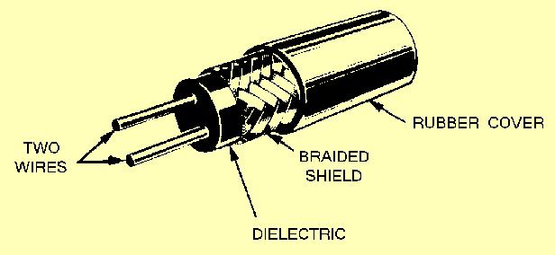
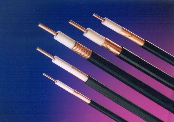
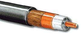
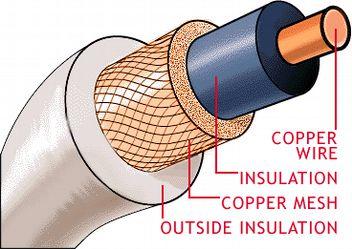
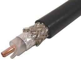
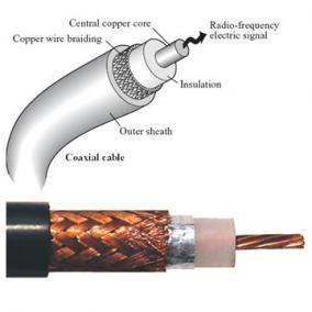
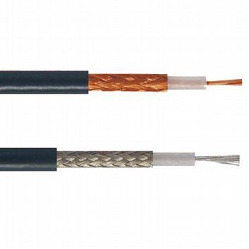
21 Unbalanced (Coaxial) Transmission Lines -2 conductors on same axis -center conductor + shield Z0 = 138/ e x log D/d e = dielectric constant D = outer conductor diameter d = inner conductor diameter Velocity factor: transmission speed in trans. line as a fraction of c : typical 0.66, 0.82 (coax), 0.99 (balanced line) Advantages Unaffected by nearby conductors Waterproof Easy to install Disadvantages More lossy than balanced Special connectors Ruined by water Z matching more important
22
23 El Cheapo!
24 Specific cable line losses. Losses greater with any mis-match!! per 100


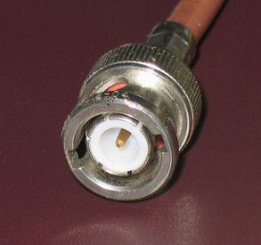
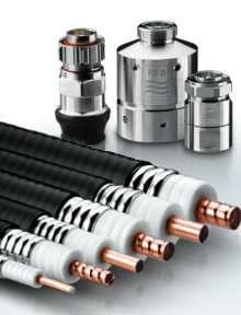
25 Common Coaxial Connector Types BNC SO-239 => UHF Type N Type PL-259 => UG adaptors


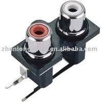

26 The F connector family (usually 72Ω) RCA connector family: now some for audio, some for RF SMA: most recent, small, good into UHF
Optimizing Your Stations Performance
 Optimizing Your Stations Performance A few hints / techniques, recommendations for getting the most RF out to the Antenna from your HF, VHF / UHF station. Tonights Presenters: Doug Theriault NO1D John
Milton Keynes Amateur Radio Society (MKARS)
") Milton Keynes Amateur Radio Society (MKARS) Intermediate Licence Course Feeders Antennas Matching (Worksheets 31, 32 & 33) MKARS Intermediate Licence Course - Worksheet 31 32 33 Antennas Feeders Matching
Milton Keynes Amateur Radio Society (MKARS) Intermediate Licence Course Feeders Antennas Matching (Worksheets 31, 32 & 33) MKARS Intermediate Licence Course - Worksheet 31 32 33 Antennas Feeders Matching
COAXIAL TRANSMISSION LINE COMMON-MODE CURRENT
 COAXIAL TRANSMISSION LINE COMMON-MODE CURRENT Introduction Coaxial transmission lines are popular for their wide frequency bandwidth and high resistance to electromagnetic interference (EMI). Coax cables
1) Transmission Line Transformer a. First appeared on the scene in 1944 in a paper by George Guanella as a transmission line transformer, the 1:1
 Transmission Line Transformer a. First appeared on the scene in 1944 in a paper by George Guanella as a transmission line transformer, the 1:1") 1) Transmission Line Transformer a. First appeared on the scene in 1944 in a paper by George Guanella as a transmission line transformer, the 1:1 Guanella Balun is the basic building Balun building block.
1) Transmission Line Transformer a. First appeared on the scene in 1944 in a paper by George Guanella as a transmission line transformer, the 1:1 Guanella Balun is the basic building Balun building block.
ARNSW Balun Day. Balun construction
 ARNSW Balun Day Balun construction Typical Baluns All built from locally available components. Balun uses Most baluns are used to match the 50Ω output of a transceiver to an antenna. A centre fed dipole
Jacques Audet VE2AZX. Nov VE2AZX 1
 Jacques Audet VE2AZX VE2AZX@amsat.org Nov. 2006 VE2AZX 1 - REASONS FOR USING A BALUN - TYPES OF BALUNS - CHECK YOUR BALUN WITH AN SWR ANALYZER - MEASURING THE IMPEDANCE OF A NUMBER OF FERRITES - IMPEDANCE
Technician License. Course
 Technician License Course Technician License Course Chapter 4 Lesson Plan Module - 9 Antenna Fundamentals Feed Lines & SWR The Antenna System The Antenna System Antenna: Transforms current into radio waves
Technician Licensing Class. Antennas
 Technician Licensing Class Antennas Antennas A simple dipole mounted so the conductor is parallel to the Earth's surface is a horizontally polarized antenna. T9A3 Polarization is referenced to the Earth
Technician License Course Chapter 4. Lesson Plan Module 9 Antenna Fundamentals, Feed Lines & SWR
 Technician License Course Chapter 4 Lesson Plan Module 9 Antenna Fundamentals, Feed Lines & SWR The Antenna System Antenna: Transforms current into radio waves (transmit) and vice versa (receive). Feed
and Related Topics W7KVI, HARC Original: 3/26/16
 Baluns, Ununs, and Related Topics W7KVI, HARC Original: 3/26/16 This Presentation Informal & brisk - 52 slides (too many unless you re an enthusiast!) Discussion encouraged if not extensive, interrupt
Cray Valley Radio Society. Real Life Wire Antennas
 Cray Valley Radio Society Real Life Wire Antennas 1 The basic dipole The size of an antenna is determined by the wavelength of operation In free space: ~3x10 8 m/s Frequency x Wavelength = Speed of Light,
A TRANSMISSION LINE BALANCE TEST METER
 by Lloyd Butler VK5BR with modifications by Phil Storr VK5SRP. Here is a simple meter to check the balance of currents running in the two legs of a transmission line. It can be used to check the balance
What is a BALUN or UNUN:
 What is a BALUN or UNUN: A device to connect different types of antennas to various feed lines. Can transform impedances, choke common mode or change balanced to unbalanced BALUN Balanced to Unbalanced
Technician License. Course
 Technician License Course Technician License Course Chapter 4 Lesson Plan Module - 10 Practical Antennas The Dipole Most basic antenna The Dipole Most basic antenna The Dipole Total length is ½ wavelength
Improved Ionospheric Propagation With Polarization Diversity, Using A Dual Feedpoint Cubical Quad Loop
 Improved Ionospheric Propagation With Polarization Diversity, Using A Dual Feedpoint Cubical Quad Loop by George Pritchard - AB2KC ab2kc@optonline.net Introduction This Quad antenna project covers a practical
Technician Licensing Class T9
 Technician Licensing Class T9 Amateur Radio Course Monroe EMS Building Monroe, Utah January 11/18, 2014 January 22, 2014 Testing Session Valid dates: July 1, 2010 June 30, 2014 Amateur Radio Technician
Antenna Design for FM-02
 Antenna Design for FM-02 I recently received my FM-02 FM transmitter which I purchased from WLC. I researched the forum on what antennas where being used by the DIY community and found a nice write-up
Transmission lines. Characteristics Applications Connectors
 Transmission lines Characteristics Applications Connectors Transmission Lines Connect They allow us to conduct RF Signals between our station components, they connect: Transceivers Antennas Tuners Amplifiers
4/29/2012. General Class Element 3 Course Presentation. Ant Antennas as. Subelement G9. 4 Exam Questions, 4 Groups
 General Class Element 3 Course Presentation ti ELEMENT 3 SUB ELEMENTS General Licensing Class Subelement G9 Antennas and Feedlines 4 Exam Questions, 4 Groups G1 Commission s Rules G2 Operating Procedures
RF Transmission Lines & SWR
 RF Transmission Lines & SWR After installing the Antenna and finding a place for the Transceiver, you must connect the two together and the Antenna is usually located at some distance away from the Transceiver.
4/25/2012. Supplement T9. 2 Exam Questions, 2 Groups. Amateur Radio Technician Class T9A: T9A: T9A: T9A:
 Amateur Radio Technician Class Element 2 Course Presentation ti ELEMENT 2 SUB-ELEMENTS Technician Licensing Class Supplement T9 Antennas, Feedlines 2 Exam Questions, 2 Groups T1 - FCC Rules, descriptions
WHY YOU NEED A CURRENT BALUN
 HF OPERATORS WHY YOU NEED A CURRENT BALUN by John White VA7JW NSARC HF Operators 1 What is a Balun? A BALUN is a device typically inserted at the feed point of a dipole-like antenna wire dipoles, Yagi
General License Class Chapter 6 - Antennas. Bob KA9BHD Eric K9VIC
 General License Class Chapter 6 - Antennas Bob KA9BHD Eric K9VIC Learning Objectives Teach you enough to get all the antenna questions right during the VE Session Learn a few things from you about antennas
The Amazing MFJ 269 Author Jack Tiley AD7FO
 The Amazing MFJ 269 Author Jack Tiley AD7FO ARRL Certified Emcomm and license class Instructor, Volunteer Examiner, EWA Technical Coordinator and President of the Inland Empire VHF Club What Can be Measured?
The Balun and The UNUN - page 1
 The Balun and The UNUN - page 1 When is a Balun, not a balun, when it is an UNUN! Balun = "BALanced-to-UNbalanced" Unun = "UNbalanced-to-UNbalanced" Looking at the two diagrams above you will see the common
QUICK REFERENCE GUIDE
 QUICK REFERENCE GUIDE Installation 1. Install a ground system for DC noise suppression and RFI suppression 2. Install your DC power supply 3. Install lightning protection. This will help protect more than
Least understood topics by most HAMs RF Safety Ground Antennas Matching & Feed Lines
 Least understood topics by most HAMs RF Safety Ground Antennas Matching & Feed Lines Remember this question from the General License Exam? G0A03 (D) How can you determine that your station complies with
Amateur Extra Manual Chapter 9.4 Transmission Lines
 9.4 TRANSMISSION LINES (page 9-31) WAVELENGTH IN A FEED LINE (page 9-31) VELOCITY OF PROPAGATION (page 9-32) Speed of Wave in a Transmission Line VF = Velocity Factor = Speed of Light in a Vacuum Question
SOME USES FOR RF1,RF5 and VA1 ANALYSTS. SWR Measurement
 SOME USES FOR RF1,RF5 and VA1 ANALYSTS THE HANDIEST INSTRUMENTS IN DECADES! When you put up an antenna in the the old days, it could be a real struggle. The only way to tell if it was tuned to the right
The Balun and The UnUn - page 1
 The Balun and The UnUn - page 1 When is a Balun, not a Balun, when it is an UnUn! Balun = "Balanced-to-Unbalanced" UnUn = "Unbalanced-to-Unbalanced" Looking at the two diagrams above you will see the common
The first thing to realize is that there are two types of baluns: Current Baluns and Voltage Baluns.
 Choosing the Correct Balun By Tom, W8JI General Info on Baluns Balun is an acronym for BALanced to UNbalanced, which describes certain circuit behavior in a transmission line, source or load. Most communications
Table of Contents. MFJ-1778 G5RV Multiband Antenna
 Table of Contents MFJ-1778 G5RV Multiband Antenna Introduction... 1 Theory Of Operation... 1 80 meter band:... 1 40 meter band:... 1 30 meter band:... 2 20 meter band:... 2 17 meter band:... 2 15 meter
FCC Technician License Course
 FCC Technician License Course 2014-2018 FCC Element 2 Technician Class Question Pool Presented by: Tamiami Amateur Radio Club (TARC) WELCOME To the third of 4, 3-hour classes presented by TARC to prepare
Technician License Course Chapter 4. Lesson Plan Module 10 Practical Antennas
 Technician License Course Chapter 4 Lesson Plan Module 10 Practical Antennas The Dipole Most basic antenna Total length is ½ wavelength (½ λ) Usual construction: Two equal halves of wire, rod, or tubing
WA4DXP. Mobile Antennas. Mounts, Antennas, Tuners (or not) & grounding Presented by M.D. Smith
 & grounding Presented by M.D. Smith") WA4DXP Mobile Antennas Mounts, Antennas, Tuners (or not) & grounding Presented by M.D. Smith Mounts Mobile Antennas WA4DXP Bolt on antenna mount... Same as used on heavy truck mirror mount Sheet metal
WA4DXP Mobile Antennas Mounts, Antennas, Tuners (or not) & grounding Presented by M.D. Smith Mounts Mobile Antennas WA4DXP Bolt on antenna mount... Same as used on heavy truck mirror mount Sheet metal
A Transmatch for Balanced or Unbalanced Lines
 A Transmatch for Balanced or Unbalanced Lines Most modern transmitters are designed to operate into loads of approximately 50 Ω. Solid-state transmitters produce progressively lower output power as the
MFJ-219/219N 440 MHz UHF SWR Analyzer TABLE OF CONTENTS
 MFJ-219/219N 440 MHz UHF SWR Analyzer TABLE OF CONTENTS Introduction...2 Powering The MFJ-219/219N...3 Battery Installation...3 Operation Of The MFJ-219/219N...4 SWR and the MFJ-219/219N...4 Measuring
MFJ-835 RF Ammeter. Introduction. Uses
 MFJ-835 RF Ammeter Introduction Congratulations on purchasing the MFJ-835 Balanced Line RF Ammeter. The MFJ-835 is designed for measuring balanced RF feedline current on 1.8-30 MHz while having low interaction
The design of Ruthroff broadband voltage transformers M. Ehrenfried G8JNJ
 The design of Ruthroff broadband voltage transformers M. Ehrenfried G8JNJ Introduction I started investigating balun construction as a result of various observations I made whilst building HF antennas.
Chapter 6 Antenna Basics. Dipoles, Ground-planes, and Wires Directional Antennas Feed Lines
 Chapter 6 Antenna Basics Dipoles, Ground-planes, and Wires Directional Antennas Feed Lines Some General Rules Bigger is better. (Most of the time) Higher is better. (Most of the time) Lower SWR is better.
4 Antennas as an essential part of any radio station
 4 Antennas as an essential part of any radio station 4.1 Choosing an antenna Communicators quickly learn two antenna truths: Any antenna is better than no antenna. Time, effort and money invested in the
Users Manual. 200W HF/50MHz Band Auto Antenna Tuner. Model HC-200AT
 Users Manual 200W HF/50MHz Band Auto Antenna Tuner Model HC-200AT Caution 1. Never remove or open the tuner cover while transmitting. When there is RF in the circuits of the tuner, there will be high voltage
Chapter 12: Transmission Lines. EET-223: RF Communication Circuits Walter Lara
 Chapter 12: Transmission Lines EET-223: RF Communication Circuits Walter Lara Introduction A transmission line can be defined as the conductive connections between system elements that carry signal power.
How to Blow Up Your Balun
 How to Blow Up Your Balun (and other things too ) By Dean Straw, N6BV Sea-Pac June 7, 2014 Photos courtesy Jim Brown, K9YC 1 This is What I Intend to do Today I will examine stresses placed on common-mode
Technician License Course Chapter 4
 Technician License Course Chapter 4 Propagation, Basic Antennas, Feed lines & SWR K0NK 26 Jan 18 The Antenna System Antenna: Facilitates the sending of your signal to some distant station. Feed line: Connects
The J-Pole Antenna. Gary Wescom
 The J-Pole Antenna Gary Wescom - 2018 Much has been written about the J-Pole antenna. A simple Google search will net days worth of reading material on the subject. That would tend to indicate this paper
L. B. Cebik, W4RNL. Basic Transmission Line Properties
 L. B. Cebik, W4RNL In the course of developing this collection of notes, I have had occasion to use and to refer to both series and parallel coaxial cable assemblies. Perhaps a few notes specifically devoted
MFJ-834 RF Ammeter. Introduction. Uses
 MFJ-834 RF Ammeter Introduction Congratulations on purchasing the MFJ-834 RF Ammeter. The MFJ-834 is designed for measuring in-line RF feedline current on 1.8-30 MHz while having low interaction on the
A short, off-center fed dipole for 40 m and 20 m by Daniel Marks, KW4TI
 A short, off-center fed dipole for 40 m and 20 m by Daniel Marks, KW4TI Version 2017-Nov-7 Abstract: This antenna is a 20 to 25 foot long (6.0 m to 7.6 m) off-center fed dipole antenna for the 20 m and
I recently came across a No-Counterpoise antenna described by designed by Peter Millis M3KXZ and based on an original design by K9ESE.
 M3KXZ 'no counterpoise' antenna I recently came across a No-Counterpoise antenna described by designed by Peter Millis M3KXZ and based on an original design by K9ESE. Details of the antenna can be found
EVERY rotor control, remote antenna selector also has a common mode choke at each end of the cable!
 Radio Communication Choosing a Coax Feed Line Choke By Bob Brehm, AK6R RFI Tip Sheet #RC-1 How to choose feed line chokes, line isolators, baluns, or ununs for coax fed dipoles, verticals, hex beams, slopers,
How to use your antenna tuner.
 How to use your antenna tuner. There's more to it than what is in your manual or on most how to do it websites! http://www.arrl.org/tis/info/ant-tuner-op.html Here is a neat site with a "T" network simulator.
Transmission Line Signal Sampling By Don Steinbach, AE6PM
 Transmission Line Signal Sampling By Don Steinbach, AE6PM When I was finalizing the mechanical layout of my remotely-operated 3-position coaxial antenna switch (Fig. 1), I wanted to include a way to bring
SWR myths and mysteries.
 SWR myths and mysteries. By Andrew Barron ZL3DW September 2012 This article will explain some of the often misunderstood facts about antenna SWR at HF and uncover some popular misconceptions. The questions
MFJ-249B HF/VHF SWR ANALYZER
 TABLE OF CONTENTS MFJ-249B... 2 Introduction... 2 Powering The MFJ-249B... 3 Battery Installation... 3 Alkaline Batteries... 3 NiCd Batteries... 4 Power Saving Mode... 4 Operation Of The MFJ-249B...5 SWR
Technician Licensing Class. Lesson 4. presented by the Arlington Radio Public Service Club Arlington County, Virginia
 Technician Licensing Class Lesson 4 presented by the Arlington Radio Public Service Club Arlington County, Virginia 1 Quiz Sub elements T6 & T7 2 Good Engineering Practice Sub element T8 3 A Basic Station
Remote Automatic Antenna Tuners and the 43 Foot Vertical
 PRODUCT REVIEW Remote Automatic Antenna Tuners and the 43 Foot Vertical Reviewed by Phil Salas, AD5X QST Contributing Author QST has previously reviewed in-shack and remote automatic antenna tuners designed
Microair Avionics Pty Ltd ABN VHF Aerial Installation FAQ
 Pty Ltd ABN 92 091 040 032 P O Box 5532 Airport Drive Bundaberg West Queensland 4670 Australia Phone: Fax: Email: Web: 07 4155 3048 +61 7 4155 3048 07 4155 3049 +61 7 4155 3049 support@microair.com.au
MFJ-208 VHF SWR Analyzer
 MFJ-208 VHF SWR Analyzer Thank you for purchasing the MFJ-208 VHF SWR Analyzer. The MFJ-208 gives you a direct readout of your antenna's SWR without the need for formulas or indirect readings. The MFJ-
Adjust Antenna Tuners Antenna Measurements Capacitor Measurement Measure Feed Point Impedance Measure Ground Loss Inductor Measurement
 The Micro908 antenna analyzer is an extremely useful instrument to have around the ham shack or homebrewer s workbench. This section describes the basic uses, as well as some advanced techniques for which
Newcomers And Elmers Net: Wire Antennas Robert AK3Q
 Newcomers And Elmers Net: Wire Antennas 02-07-16 Robert AK3Q Wire antennas represent one of the greatest values in the radio hobby world. For less than the cost of a good meal out on the town you can buy
End Fed Half Wave Antenna Coupler
 End Fed Half Wave Antenna Coupler The finished End Fed Half Wave antenna coupler. Centre fed half wave dipoles make great, simple and effective antennas for the HF bands. Sometimes however, the centre
Antenna Disconnect THE INEXPENSIVE WAY TO PROTECT YOUR VALUABLE RADIO FROM LIGHTNING SURGES
 Antenna Disconnect THE INEXPENSIVE WAY TO PROTECT YOUR VALUABLE RADIO FROM LIGHTNING SURGES -------------------------------------------------------------------------------------- Operating Manual May 2017
Impedance, Reflections, and Transformations
 Impedance, Reflections, and Transformations Rocky Mountain Ham Radio University Chris Hamilton AE5IT 2017 December 16 Conventional wisdom: My antenna is useless above 1.5:1 SWR (Or is it 2:1? Or 3:1?)
Ameritron RCS-10 INTRODUCTION
 Ameritron RCS-10 INTRODUCTION The RCS-10 is a versatile antenna switch designed for 50-ohm systems. It handles high power, and sealed relays offer excellent life and connection reliability. It requires
Killing RF Noise for Field Day and CQP. Jim Brown, K9YC
 Killing RF Noise for Field Day and CQP Jim Brown, K9YC The Fundamental Problem RF noise is generated inside equipment The wires inside equipment, and cables that interconnect equipment, are antennas, and
Chokes and Isolation Transformers For Receiving Antennas By Jim Brown K9YC 2018 by James W. Brown All rights reserved
 Chokes and Isolation Transformers For Receiving Antennas By Jim Brown K9YC 2018 by James W. Brown All rights reserved Why We Need Them A feedline must be grounded where it enters the shack-for lightning
Antennas and Propagation Chapters T4, G7, G8 Antenna Fundamentals, More Antenna Types, Feed lines and Measurements, Propagation
 Antennas and Propagation Chapters T4, G7, G8 Antenna Fundamentals, More Antenna Types, Feed lines and Measurements, Propagation =============================================================== Antenna Fundamentals
Antenna Systems for the Recently Licensed Ham --3 Talks-- BVARC Meeting May 10 th, 2012
 Antenna Systems for the Recently Licensed Ham --3 Talks-- BVARC Meeting May 10 th, 2012 Understanding the Cardinal Rules of the Ham Radio Antenna System Rick Hiller -- W5RH Utilizing Your New Found Practical
MODEL DB-1015A 10- and 15-Meter Duo-Band Antenna Order No. 330
 MODEL DB-1015A 10- and 15-Meter Duo-Band Antenna Order No. 330 HY-GAIN ELECTRONICS CORPORATION 8601 Northeast Highway 6 Lincoln, Nebraska 68505 Telephone 464-9151 Area Code 402 TABLE OF CONTENTS page SECTION
RFI and Ferrites. Jim Brown K9YC Audio Systems Group, Inc. Santa Cruz. Primary Interference Mechanisms
 RFI and Ferrites Jim Brown K9YC Audio Systems Group, Inc. Santa Cruz jim@audiosystemsgroup.com Primary Interference Mechanisms Common-mode noise on signal wiring Pin 1 problems Improper shield termination
The Principle V(SWR) The Result. Mirror, Mirror, Darkly, Darkly
 The Result. Mirror, Mirror, Darkly, Darkly") The Principle V(SWR) The Result Mirror, Mirror, Darkly, Darkly 1 Question time!! What do you think VSWR (SWR) mean to you? What does one mean by a transmission line? Coaxial line Waveguide Water pipe Tunnel
The Principle V(SWR) The Result Mirror, Mirror, Darkly, Darkly 1 Question time!! What do you think VSWR (SWR) mean to you? What does one mean by a transmission line? Coaxial line Waveguide Water pipe Tunnel
Owen Duffy VK2OMD owenduffy.net
 Owen Duffy VK2OMD owenduffy.net owen@owenduffy.net Antenna system Differential and common mode feed line current Balun types and characteristics Insights from NEC models, measurements Example application:
Antennas and Stuff. John Kernkamp WB4YJT
 Antennas and Stuff John Kernkamp WB4YJT John Kraus W8JK June 28, 1910 - July 18, 2004 Invented the helical antenna, the corner reflector, and the W8JK End-Fire array. In 1950 designed and built the Big
Welcome to Ham Radio 201 New General / Extra Session
 Welcome to Ham Radio 201 New General / Extra Session Sponsored by Agenda New Technician / New Licensee 8:00 Kickoff 8:15 VHF/UHF Gear - George 9:00 VHF/UHF Operating - Beric 9:45 VHF Digital Voice George
Basic Wire Antennas. Part II: Loops and Verticals
 Basic Wire Antennas Part II: Loops and Verticals A loop antenna is composed of a single loop of wire, greater than a half wavelength long. The loop does not have to be any particular shape. RF power can
WCARES NEEDS YOU! CONSIDER MAKING A TECHNICAL PRESENTATION AT AN UPCOMING CHEW & CHAT MEETING LEARN SOMETHING NEW AND PRESENT
 WCARES NEEDS YOU! CONSIDER MAKING A TECHNICAL PRESENTATION AT AN UPCOMING CHEW & CHAT MEETING SHARE WHAT YOU KNOW LEARN SOMETHING NEW AND PRESENT IT CONTACT TIM AD4CJ AD4CJ@arrl.net 1 Transmission Line
MFJ Balanced Line Tuner
 MFJ Balanced Line Tuner Introduction The MFJ-974H balanced line antenna tuner is a fully balanced true balanced line antenna tuner, providing superb current balance throughout a very wide matching range
160- and 80-Meter Matching Networks for your 43-foot Vertical Phil Salas AD5X
 160- and 80-Meter Matching Networks for your 43-foot Vertical Phil Salas AD5X 43-foot verticals have become popular as they can be self supporting, are not too obtrusive, and have higher radiation resistance
Practical Antennas and. Tuesday, March 4, 14
 Practical Antennas and Transmission Lines Goals Antennas are the interface between guided waves (from a cable) and unguided waves (in space). To understand the various properties of antennas, so as to
MODERN AM BROADCAST STATIONS
 MODERN AM BROADCAST STATIONS With DDS DDS EXCITER OPERATING MANUAL 75w carrier - 300w p.e.p What is DDS IT IS THE INITIALS OF THE WORDS DIRECT DIGITAL SYNTHESIZER, THAT MEANS: DIRECT DIGITAL FREQUENCY
Lesson 9: Base Stations
 Lesson 9: Base Stations Preparation for Amateur Radio Technician Class Exam Topics Home Stations Basic Station Layout RTTY and Data Communications Station Accessories Wavelengths Feed Lines Impedance-matching
What causes the Out-of-Balance Current in the coax and why does it Radiate?
 The EH Antenna - Out of Balance Current or Longitudinal Mode Current in the Coaxial Cable causes radiation from the coax. But how large a proportion of the total power is radiated or lost from this Current?
INSTALLATION AND CONNECTIONS
 INSTALLATION AND CONNECTIONS 3 Unpacking After unpacking, immediately report any damage to the delivering carrier or dealer. Keep the shipping cartons. For a description and a diagram of accessory equipment
1.5 kw Automatic Remote Controlled Antenna Tuner for Verticals and other Unbalanced Antennas
 1.5 kw Automatic Remote Controlled Antenna Tuner for Verticals and other Unbalanced Antennas Mod. AT- 615U Short Form Manual 10/2010 Dipl.Ing. Klaus Bemmerer RF Communication Electronics Niendorf-Middeldor
Rx antennas at IV3PRK: the 4-Square Rx Vertical Array
 Rx antennas at IV3PRK: the 4-Square Rx Vertical Array Part 2: putting all stuff together and construction details Calculating the cable lengths by Pierluigi Luis Mansutti IV3PRK The most difficult choice,
Bead RF Chokes. By: Igor Grigorov, VA3ZNW, Richmond Hill, Canada
 By: Igor Grigorov, VA3ZNW, Richmond Hill, Canada Recently there are lots devices that contained some RF sensitive or vice versa RF generation parts inside. It is power AC/DC converters (aka power supply),
Weekend Antennas No. 5 The "Compact Quad" Multiband Antenna
 Weekend Antennas No. 5 The "Compact Quad" Multiband Antenna When I relocated to Johannesburg I needed a new multiband HF antenna. Since I was staying in a rented house a tower was out of the question,
Bob Brehm, AK6R Chief Engineer Palomar-Engineers.com
 Bob Brehm, AK6R Chief Engineer Palomar-Engineers.com LAKESIDE - October 2017 This presentation available on website Copyright 2013-2017 Palomar Engineers, Inc. End Fed Workshop Topics Popular End Fed Antenna
Array Solutions 350 Gloria Rd Sunnyvale, TX USA PHN FAX
 Array Solutions 350 Gloria Rd Sunnyvale, TX 75182 USA PHN 972 203 2008 FAX 972 203 8811 E-MAIL sales@arraysolutions.com Model AS-AYL-4 4-way K9AY Loop System This is the popular K9AY Loop receiving antenna,
CP6 6 Band Trap Vertical 80-6m
 CP6 6 Band Trap Vertical 80-6m Instruction Sheet The CP6 is a multi-band trap-vertical antenna for HF bands, covering the 80*, 40, 20, 15, 10m & 6m amateur bands. Made from heavy duty aluminum, the CP6
MFJ-969 Versa Tuner II Instruction Manual
 MFJ-969 Versa Tuner II Instruction Manual General Information The MFJ-969 is a 300 watt RF output power antenna tuner that will match any transmitter or transceiver to virtually any antenna. Peak or average
Magnetic Loop Antenna - Topbands
 Magnetic Loop Antenna - Topbands Instruction Manual Thank you for purchasing this new product small Magnetic Loop Antenna Topbands. Manual contains important information. Please read all instructions carefully
General Licensing Class Circuits
 General Licensing Class Circuits Valid July 1, 2011 Through June 30, 2015 1 Amateur Radio General Class Element 3 Course Presentation ELEMENT 3 SUB-ELEMENTS (Groupings) Your Passing CSCE Your New General
FilterMax IV 200W Bandpass Filter System. by Hamation
 FilterMax IV 200W Bandpass Filter System by Hamation Hamation, 2013 Introduction Six bands in one integrated unit 200W power rating SWR less than 1.25 across band Low insertion loss < 0.6db High rejection
Intermediate Course (5) Antennas and Feeders
 Antennas and Feeders") Intermediate Course (5) Antennas and Feeders 1 System Transmitter 50 Ohms Output Standing Wave Ratio Meter Antenna Matching Unit Feeder Antenna Receiver 2 Feeders Feeder types: Coaxial, Twin Conductors
Intermediate Course (5) Antennas and Feeders 1 System Transmitter 50 Ohms Output Standing Wave Ratio Meter Antenna Matching Unit Feeder Antenna Receiver 2 Feeders Feeder types: Coaxial, Twin Conductors
MFJ-941E Versa Tuner II GENERAL INFORMATION:
 GENERAL INFORMATION: MFJ VERSA TUNER II The MFJ-941E is designed to match virtually any transmitter to any antenna, including dipoles, inverted-vees, verticals, mobile whips, beams, random wires, and others
ANTENNAS. I will mostly be talking about transmission. Keep in mind though, whatever is said about transmission is true of reception.
 Reading 37 Ron Bertrand VK2DQ http://www.radioelectronicschool.com ANTENNAS The purpose of an antenna is to receive and/or transmit electromagnetic radiation. When the antenna is not connected directly
Portable Vertical Antenna for 75m & 40m
 Portable Vertical Antenna for 75m & 40m BOXBORO August 2012 Jacques VE2AZX Web: ve2azx.net 1 Objectives 1- Portable Antenna for 75m et 40m 2- Low radiation angle for DX 3- Efficient 4- Easy to install.
This paper is meant assist in the operation and understanding of the VIA Bravo Family of products.
 Abstract: This paper is meant assist in the operation and understanding of the VIA Bravo Family of products. Understanding the Display and its Readings: The VIA Bravo display provides graphical and numerical