Technician License Course Chapter 3 Operating Station Equipment. Transmitters, Receivers and Transceivers PHYS 401 P. Reiff 2009
|
|
|
- Dwain Ellis
- 6 years ago
- Views:
Transcription


1 Technician License Course Chapter 3 Operating Station Equipment Transmitters, Receivers and Transceivers PHYS 401 P. Reiff 2009
2 Generalized Transceiver Categories Single Band Dual Band Multi-mode Multi-band Hand-held (HT) VHF or UHF FM VHF/UHF FM VHF/UHF HF and VHF/UHF VHF/UHF
3 Single Band Transceiver Probably the most common starter rig. Operates from 12 volts dc, requires external power supply. Requires an external antenna. Can be operated mobile or as a base station. Limited to frequency modulation (FM) and either 2 meters or 70 cm bands. Up to approximately 50 watts output.
4 Dual Band Transceiver Same as the single band transceiver but includes additional band(s). Most common are 2 m and 70 cm bands. Could be tri-bander. Depending on antenna connectors, might require separate coax for each band or a duplexer for single coax.
5 Multi-Mode Transceiver Can be single or dual band. Main difference is that these rigs can operate on all major modes SSB/AM/FM, CW, Data, RTTY etc. More features add complexity and cost. Most flexible of the rigs that will allow you to explore new modes as you gain experience.
6 Multi-Band Transceiver Covers all bands can be limited to HF or can be HF/VHF/UHF (even can listen on frequencies you can t transmit on). Also covers all modes. Frequently 100 watts on HF, some power limitations on high bands (50 watts). Larger units have internal power supplies, smaller units require external power (12 V).
7 Hand-held (HT) Transceiver Small hand-held FM units. Can be single band or dual band (sometimes more). Limited power (usually 5 watts or less). Includes power (battery) and antenna in one package. An attractive first starter rig but make sure it is what you want.
8 Side-by-Side Single Band Dual Band Multi-mode Multi-band HT Freq Agility Limited Medium Medium Full Limited Functionality Limited Limited Full Full Limited Ease of Use Easy Medium Medium Difficult Easy Programming Easy Easy Medium Challenging Easy/Medium Power Low Low Medium High Low Cost Low Modest High High Low
9 Rig Vocabulary We will now go through some jargon and vocabulary specific to the functions and controls of a transmitter and receiver. This is a way to discuss how to operate a transceiver. These controls, though separate, are combined in a transceiver.
10 Transmitter Controls and Functions Main tuning dial (both TX (trans) and RX (receive)): Controls the frequency selection via the Variable Frequency Oscillator (VFO). Could be an actual dial or key pad or programmed channels. Variable frequency step size (tuning rate, resolution). Could have more than one VFO (control more that one frequency at a time).
11 Transmitter Controls and Functions Mode selector (both TX and RX multimode rigs). AM/FM/SSB (LSB or USB) CW Data (RTTY) Could be automatic based on recognized band plan.
12 Transmitter Controls and Functions Microphone controls Gain How loudly you need to talk to be heard. Speech Compressor or Speech Processor Compacting your speech into a narrow frequency range to enhance punch. Too much gain or compression can cause problems. Splatter Over-deviation Over-modulation
13 Transmitter Controls and Functions Automatic Level Control (ALC). Automatically limits transmitter drive (output level) to prevent problems associated with too much gain or compression. Also can control external power amplifier operation.
14 Transmitter Controls and Functions Transmitter on/off Push-to-Talk (PTT) Voice-Operated Transmission (VOX) VOX Gain (beefs up your speech) VOX Delay (reduces sending background beeps) Anti-VOX (won t retransmit when your speaker is live no echoes) Key jack (to plug in your CW keyer)
15 Transmitter Controls and Functions Microphones (Mic) Hand mics Desk mics Preamplified desk mikes Speaker-mics Headsets or boom-sets Internal mikes Speak across the mic, not into the mic.
16 Transmitter Controls and Functions Morse Keys Straight Semi-automatic (Bug) Electronic keyer, paddle One paddle dash, one paddle dot Can be reversed for lefties
17 Receiver Controls and Functions AF Gain or Volume Controls the audio level to the speaker or headphones. RF Gain Controls the strength of radio signal entering the receiver. Used to limit (attenuate) very strong local signals. Usually operated in the full-open position.
18 Receiver Controls and Functions Automatic Gain Control (AGC) Automatically limits the incoming signals during signal (voice) peaks. Prevents peaks from capturing the receiver and limiting reception of lower level portions of the incoming signal. Fast setting for CW. Slow settings for SSB and AM. Not used in FM because of the type of signal used in FM.
19 Receiver Controls and Functions Squelch Turns off audio to speaker when signal is not present. Used in FM primarily Open allows very weak signals to pass through (along with noise). Tight allows only the strongest signals to pass through. Advance the squelch control until the noise just disappears.
20 Receiver Controls and Functions Filters Band-pass filter Used to narrow the width of signal that is passed. Can attenuate adjacent interference. Notch filter Very narrow filter that can be moved over an interfering signal to attenuate it. Noise blanker or limiter Limits signal spikes that are frequently associated with random naturally generated noise.
21 Receiver Controls and Functions Reception and Transmission Meter. In transmit, indicates output power or ALC or other functions as selected by switch setting. In receive - indicates signal strength. In S units S1 through S9 S9 is strongest. Also have db over S9 to cover very strong signals.
22 Receiver Controls and Functions Receivers can be limited to ham bands or can cover other parts of the spectrum. General coverage receivers cover a wide area of the spectrum and can be used for shortwave listening (SWL).
23 What is a Repeater? Specialized transmitter/receiver interconnected by computer controller. Generally located at a high place. Receives your signal and simultaneously retransmits your signal on a different frequency (standard offsets:.6 Mhz VHF). Dramatically extends line-of-sight range. If both users can see the repeater site.
24
25 A Little Vocabulary First Simplex Transmitting and receiving on the same frequency. Each user takes turns to transmit. Is the preferred method if it works. National VHF simplex frequency:
26 A Little Vocabulary First Duplex Transmitting on one frequency while simultaneously listening on a different frequency. Repeaters use duplex (and some DX sites too). Output frequency the frequency the repeater transmits on and you listen to (shown in the list). Input frequency the frequency the repeater listens to and you transmit on. (In a list often shown as + or the standard shift.
27 Things to Know to Use a Repeater Output frequency. Frequency split. and therefore the input frequency. Repeater access tones (if any). Generally PL (steady) subaudible tones Rarely coded tones
28 Repeater Output Frequency Repeaters are frequently identified by their output frequency. Meet you on the machine. Here the specific frequency is used. Let s go to 94. Here an abbreviation for a standard repeater channel is used meaning MHz. How about the NARL repeater? Here the repeater is referenced by the sponsoring club name.

29 Repeater Frequency Split The split, shifts, or offset frequencies are standardized to help facilitate repeater use. There are + and shifts depending on the plan. Different bands have different standardized amounts of shift.
30 Repeater Access Tones Sometimes multiple repeaters can be accessed at the same time unintentionally. To preclude unintentional access, some repeaters require a special subaudible tone to be present before the repeater controller will recognize the signal as a valid signal and turn on the repeater. These tones are called by various names (depending on equipment manufacturer). CTCSS PL Privacy codes or tones
31 Repeater Access Tones Access tones are usually published along with repeater frequencies. Could also be announced when the repeater identifies. PL is Tones are generally programmed into the radio along with frequency and offset.
32 Repeater Controller Computer that controls the repeater operation. Station identification (Morse code or synthesized voice). Same ID requirements as you have. Time-out protection. Sometimes called the alligator. Protects against continuous transmission in the event of a stuck PTT or long winded hams. Courtesy tone repeater time-out timer reset.
33 Data Modes Connecting computers via ham radio. Some systems use radio to connect to Internet gateways. The bulk of the work is done by specialized modems or computer software/sound card. Terminal Node Controller (TNC). Multiple Protocol Controller (MPC).
34 TNC MPC Provide digital interface between computer and radio. Package the data into proper format. Convert digital data into audio tones representing 1s and 0s of digital data. Send/receive tones to transceiver. Control the transceiver.

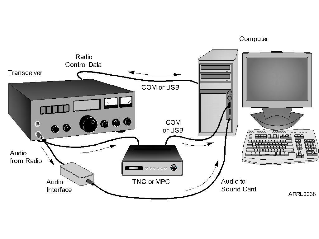
35 Data Station Setup
36 Antennas: The Dipole Most basic antenna. Two conductive, equal length parts. Feed line connected in the middle. Total length is ½ wavelength (1/2 l). Length (in feet) = 468 / Frequency (in MHz).
37 The Dipole
38 The Ground-Plane Simply a dipole that is oriented perpendicular (vertical to the Earth s surface). One half of the dipole is replaced by the groundplane. Earth Car roof or trunk lid or other metal surface. Radial wires. Length (in feet) = 234 / Frequency (in MHz).
39 The Ground-Plane
40 Loop Antennas Dipole Variations Quad (4 legs) Delta (3 legs) Horizontal (generally 4 legs around a rooftop)
41 Directional (Beam) Antennas Beam antennas focus or direct RF energy in a desired direction. Gain An apparent increase in power in the desired direction (both transmit and receive). Yagi (rod-like elements TV antennas). Quad (square wire loop elements).
42 Directional (Beam) Antennas Multiples beams away from the reflector Yagi beams towards the shortest elements
43 Directional (Beam) Antennas All beam antennas have parts called elements. Driven element connected to the radio by the feed line. Reflector element is on the back side. Director element is on the front side toward the desired direction.
44 Coax Feed Lines RG-58 RG-8 RG-213 RG-174 Hardline (differ in thickness, resistance to UV or outgassing)

45 Coax Connectors SO-239/PL259 BNC N SMA
46 Feed Line Devices Balun (Balanced to Unbalanced. Needed for ladder lines) Duplexer (one antenna, two feeds) Antenna switches SWR meter Antenna analyzer Antenna tuners
 (note ground plane wires to allow a short vertical high up on a")
47 Antenna Supports Trees. Towers or masts. Covenants and antenna restrictions must be considered. 200 ft TX limit (aircraft) (note ground plane wires to allow a short vertical high up on a mast)
48 Power Supplies Most modern radio equipment runs from 12 volts dc. Household current is 120 volts ac. Power supplies convert 120 volts ac to 12 volts dc volts dc is the common voltage you will see. This is the charging voltage for motorized vehicles. Most equipment can handle V
49 Power Supply Ratings Voltage and Current Continuous duty how much current can be supplied over the long term. Intermittent duty how much surge current can be supplied over the short term. Regulation how well the power supply can handle rapid current changes.
50 Types of Power Supplies Linear: Transformers Heavy (physically) Heavy duty current Expensive Switching: Electronics instead of transformers Light weight and small Not as robust Less expensive
51 Inverters and Generators Inverters convert dc into ac. Square, triangle, sine-wave inverters. Can be choppy Generators create ac. Gas powered. Various voltage and current ratings. Special precautions.
52 Batteries Create current through a chemical reaction. Made up of individual cells (approximately 1.5 volts per cell) connected in series or parallel. Battery types. Disposable. Rechargeable. Storage. Power capabilities rated in Ampere-hours. Amps * time. (longer usage if you use less power)
53 Battery Charging Some batteries can be recharged, some cannot. Use the proper charger for the battery being charged. Batteries will wear out over time. Best if batteries are maintained fully charged. Over-charging will cause heating and could damage the battery. Some batteries (lead-acid) may release toxic (or explosive) fumes during charging so require ventilation.
54 Handheld Transceivers Single, dual and multi-band versions (with increasing cost and complexity). Some have expanded receiver coverage (wideband receive: DC to daylight ). Very portable and self-contained. Internal microphone and speaker. Rubber duck antenna (short). (can attach to external mag-mount antenna on car) Battery powered.
55 Nice to have handheld accessories Extra battery packs. Drop-in, fast charger. Extended antenna. External microphone and speaker. Headset.
56 Radio Frequency Interference (RFI) Unwanted, unintentional signals from some electronic device that interferes with radio wave reception. You can prevent creating RFI by operating your transmitting equipment properly.
57 RFI Mitigation Filters Filters attenuate (reduce) interfering signals but do not totally eliminate them. High-pass generally on the receive side. (e.g. filter out car ignition noise) Low-pass generally on the transmit side. Band-pass used within most radio equipment.
58 Types of RFI Direct detection offending signals get into the electronics circuits to cause interference. Overload strong signal that overwhelms the weaker, wanted signal. Harmonics even multiples of the offending signal that coincide with the wanted signal.
59 Cable TV Interference Usually the result of broken shielding somewhere in the cable. Loose connections. Broken connections. Corroded connections. Usually solved by proper cable maintenance by cable supplier. If the subscriber is a legitimate subscriber.
60 Noise Sources Electrical arcs (motors, thermostats, electric fences, neon signs). Power lines. (NEW concern: BPL = internet on power lines) Motor vehicle ignitions. Motor vehicle alternators. Switching power supplies. Computers, networks, and TV sets. Hospital equipment
61 Dealing with RFI Make sure you operate your equipment properly. Eliminate interference in your own home first.
62 Dealing with RFI Take interference complaints seriously. Make sure that you re really not the cause (demonstrate that you don t interfere within your own home). Offer to help eliminate the RFI, even if you are not at fault. Consult ARRL RFI Resources for help and assistance.
63 What the Rules Say RFI from and to unlicensed devices is the responsibility of the users of such devices Bottom line If your station is operating properly, you are protected against interference complaints BUT Be a good neighbor because they may (probably) not be familiar with Part 15 rules and regulations
Technician License Course Chapter 5. Lesson Plan Module 11 Transmitters, Receivers and Transceivers
 Technician License Course Chapter 5 Lesson Plan Module 11 Transmitters, Receivers and Transceivers Generalized Transceiver Categories Mobile Single Band Dual Band All Band Multimode Handheld (HT) VHF/UHF
Technician Class Course. Session 1
 Technician Class Course Session 1 WHAT IS AMATEUR RADIO? What is Amateur Radio? Amateur (or Ham) Radio is a personal radio service authorized by the Federal Communications Commission (FCC). To encourage
Technician Licensing Class. Lesson 4. presented by the Arlington Radio Public Service Club Arlington County, Virginia
 Technician Licensing Class Lesson 4 presented by the Arlington Radio Public Service Club Arlington County, Virginia 1 Quiz Sub elements T6 & T7 2 Good Engineering Practice Sub element T8 3 A Basic Station
9/17/2012. Chapter 5. Amateur Radio Equipment. Generalized Transceiver Categories
 Chapter 5 Amateur Radio Equipment Generalized Transceiver Categories Single Band Dual Band Multimode Multiband Handheld (HT) VHF or UHF FM VHF/UHF FM VHF/UHF HF and VHF/UHF FM (VHF, UHF, or Both) 1 Single
Elmer Session Hand Out for 3/3/11 de W6WTI. Some Common Controls Found On Amateur Radio Transceivers. (From ARRL web site tutorial)
") Elmer Session Hand Out for 3/3/11 de W6WTI Some Common Controls Found On Amateur Radio Transceivers. (From ARRL web site tutorial) The placement of the controls may vary from manufacturer to manufacturer
Elmer Session Hand Out for 3/3/11 de W6WTI Some Common Controls Found On Amateur Radio Transceivers. (From ARRL web site tutorial) The placement of the controls may vary from manufacturer to manufacturer
Amateur Radio License. Radios, Power, RFI
 Amateur Radio License Radios, Power, RFI Todays Topics Types of Modulation : Chapter 2 Radio Equipment : Chapter 5 Radios Digital Communications Power Supplies and Batteries RF Interference, Grounding
Technician License. Course
 Technician License Course Technician License Course Chapter 4 Lesson Plan Module - 10 Practical Antennas The Dipole Most basic antenna The Dipole Most basic antenna The Dipole Total length is ½ wavelength
Lesson 9: Base Stations
 Lesson 9: Base Stations Preparation for Amateur Radio Technician Class Exam Topics Home Stations Basic Station Layout RTTY and Data Communications Station Accessories Wavelengths Feed Lines Impedance-matching
SUBELEMENT T4. Amateur radio practices and station set up. 2 Exam Questions - 2 Groups
 SUBELEMENT T4 Amateur radio practices and station set up 2 Exam Questions - 2 Groups 1 T4A Station setup: connecting microphones; reducing unwanted emissions; power source; connecting a computer; RF grounding;
Welcome to Ham Radio 201 New General / Extra Session
 Welcome to Ham Radio 201 New General / Extra Session Sponsored by Agenda New Technician / New Licensee 8:00 Kickoff 8:15 VHF/UHF Gear - George 9:00 VHF/UHF Operating - Beric 9:45 VHF Digital Voice George
Technician License Course Chapter 4. Lesson Plan Module 10 Practical Antennas
 Technician License Course Chapter 4 Lesson Plan Module 10 Practical Antennas The Dipole Most basic antenna Total length is ½ wavelength (½ λ) Usual construction: Two equal halves of wire, rod, or tubing
Technician Licensing Class T9
 Technician Licensing Class T9 Amateur Radio Course Monroe EMS Building Monroe, Utah January 11/18, 2014 January 22, 2014 Testing Session Valid dates: July 1, 2010 June 30, 2014 Amateur Radio Technician
FCC Technician License Course
 FCC Technician License Course 2014-2018 FCC Element 2 Technician Class Question Pool Presented by: Tamiami Amateur Radio Club (TARC) WELCOME To the third of 4, 3-hour classes presented by TARC to prepare
Technician Licensing Class. Antennas
 Technician Licensing Class Antennas Antennas A simple dipole mounted so the conductor is parallel to the Earth's surface is a horizontally polarized antenna. T9A3 Polarization is referenced to the Earth
Icom IC-9100 HF/VHF/UHF transceiver
 263 Walsall Road, Great Wyrley, Walsall, WS6 6DL Established 1997. Open Monday - Friday 9am - 5pm and Saturday 9.30am - 4pm Tel: 01922 414 796 Fax: 01922 417829 Skype: radioworld_uk Icom IC-9100 HF/VHF/UHF
4/25/2012. Supplement T9. 2 Exam Questions, 2 Groups. Amateur Radio Technician Class T9A: T9A: T9A: T9A:
 Amateur Radio Technician Class Element 2 Course Presentation ti ELEMENT 2 SUB-ELEMENTS Technician Licensing Class Supplement T9 Antennas, Feedlines 2 Exam Questions, 2 Groups T1 - FCC Rules, descriptions
Operating Station Equipment
 Amateur Radio License Class Operating Station Equipment Presented by Steve Gallafent October 3, 2007 Operating Station Equipment Modulation Modulation is the process of adding information to a radio signal
DX AM FM SSB CW PA Amateur Base Station Transceiver OWNER S MANUAL RX / TX 2 4 POWER NF CHANNEL MODE RF POWER OFF CAL OFF OFF CALIBRATE
 1 2 3 6 4050 ULA 6070 TI 80 90 100 9 DX 2517 2517 RX / TX 0 2 4 SWR WATTS SET 81012 22 1 010 3 2030 5 MOD 7 ON dbover 9 SIGNAL +20 +40+60 PA FM AM USB LSB CW POWER ON SWR NB / ANL R.BEEP +10KHz NF CHANNEL
Amateur Radio License. Propagation and Antennas
 Amateur Radio License Propagation and Antennas Todays Topics Propagation Antennas Propagation Modes Ground wave Low HF and below, ground acts as waveguide Line-of-Sight (LOS) VHF and above, radio waves
Lesson 11: Antennas. Copyright Winters Version 1.0. Preparation for Amateur Radio Technician Class Exam
 Lesson 11: Antennas Preparation for Amateur Radio Technician Class Exam Topics Antenna ½ wave Dipole antenna ¼ wave Vertical antenna Antenna polarization Antenna location Beam antennas Test Equipment Exam
GRAND STRAND AMATEUR RADIO CLUB
 The GRAND STRAND AMATEUR RADIO CLUB (GSARC) Myrtle Beach SC is offering used amateur related equipment for sale. Written bids may be submitted to the GSARC up to Friday, November 23 rd, 2018. Only currently
KENWOOD SKY COMMAND SYSTEM
 KENWOOD SKY COMMAND SYSTEM Operation Manual KENWOOD COMMINICATIONS CORPORATION KENWOOD COMMUNICATIONS CORPORATION This operation manual is used for the KENWOOD SKY COMMAND SYSTEM (hereinafter referred
Antennas and Propagation Chapters T4, G7, G8 Antenna Fundamentals, More Antenna Types, Feed lines and Measurements, Propagation
 Antennas and Propagation Chapters T4, G7, G8 Antenna Fundamentals, More Antenna Types, Feed lines and Measurements, Propagation =============================================================== Antenna Fundamentals
QUICK REFERENCE GUIDE
 QUICK REFERENCE GUIDE Installation 1. Install a ground system for DC noise suppression and RFI suppression 2. Install your DC power supply 3. Install lightning protection. This will help protect more than
LnR Precision, Inc. 107 East Central Avenue, Asheboro, NC
 LD5 CW/SSB QRP Transceiver Quick guide manual Description: At the development base of the digital signal processing unit, an algorithm is embedded for IQ processing of the channels with phase suppression
Optimizing Your Stations Performance
 Optimizing Your Stations Performance A few hints / techniques, recommendations for getting the most RF out to the Antenna from your HF, VHF / UHF station. Tonights Presenters: Doug Theriault NO1D John
SPECS FEATURES SUPPLIED ACCESSORIES. HF All Band Transceiver
 718 HF All Band Transceiver RX 0.030-29.999999MHz* TX 1.800-1.999999 MHz** 3.500-3.999999 MHz** 7.000-7.300000 MHz 10.100-10.150000 MHz 14.000-14.350000 MHz 18.068-18.168000 MHz 21.000-21.450000 MHz 24.890-24.990000
The Ham s Guide to Repeaters and Radio Etiquette
 The Ham s Guide to Repeaters and Radio Etiquette A repeater is a device which will receive a signal on one frequency and simultaneously transmit it on another frequency. FM Voice Very common. ATV Amateur
CON NEX HP. OWNER'S MANUAL Full Channel AM/FM Amateur Mobile Transceiver TABLE OF CONTENTS TUNING THE ANTENNA FOR OPTIMUM S.W.R..
 TABLE OF CONTENTS PAGE SPECIFICATIONS... 2 INSTALLATION... 3 LOCATION... 3 CON NEX - 4300HP MOUNTING THE RADIO... 3 IGNITION NOISE INTERFERENCE... 4 ANTENNA... 4 TUNING THE ANTENNA FOR OPTIMUM S.W.R..
Technician License Course Chapter 4. Lesson Plan Module 9 Antenna Fundamentals, Feed Lines & SWR
 Technician License Course Chapter 4 Lesson Plan Module 9 Antenna Fundamentals, Feed Lines & SWR The Antenna System Antenna: Transforms current into radio waves (transmit) and vice versa (receive). Feed
Ham Radio Training. Level 1 Technician Level. Presented by Richard Bosch KJ4WBB
 Ham Radio Training Level 1 Technician Level Presented by Richard Bosch KJ4WBB In this chapter, you ll learn about: What is a radio signal The characteristics of radio signals How modulation adds information
ALACHUA ARES SIMPLEX REPEATER STATION INSTRUCTION MANUAL VERSION 1.0 MARCH
 ALACHUA ARES SIMPLEX REPEATER STATION INSTRUCTION MANUAL VERSION 1.0 MARCH 23 2017 1 INTRODUCTION A simplex repeater is nothing more than a digital tape recorder that listens to an FM simplex transceiver,
LD5 CW/SSB QRP Transceiver SDR /DSP
 LD5 CW/SSB QRP Transceiver SDR /DSP Quick guide manual Description: At the development base of the digital signal processing unit, an algorithm is embedded for IQ processing of the channels with phase
Operation Manual. SlJPER ST AR Channel Mobile 5-Mode Transceiver -----~- --:.. KTSS200NXX ,, I
 Operation Manual!.,, SlJPER ST AR 2000 200 Channel Mobile 5-Mode Transceiver -----~- --:.. KTSS200NXX General Description l Frequency/Channel Chart The Super Star -2000 is a combination transmitter-receiver
Pushing performance to the pinnacle
 Pushing performance to the pinnacle The latest DSP technologies developed for the IC-7800/7700 plus over 45 years of analog circuit expertise give the IC-7600 the performance advantage. The flagship's
Class Overview. Antenna Fundamentals Repeaters Duplex and Simplex Nets and Frequencies Cool Radio Functions Review
 Class Overview Antenna Fundamentals Repeaters Duplex and Simplex Nets and Frequencies Cool Radio Functions Review Antennas Antennas An antenna is a device used for converting electrical currents into electromagnetic
Technician License Course Chapter 3 Types of Radios and Radio Circuits. Module 7
 Technician License Course Chapter 3 Types of Radios and Radio Circuits Module 7 Radio Block Diagrams Radio Circuits can be shown as functional blocks connected together. Knowing the description of common
FT-897 Alignment. Local Oscillator Adjustment. PLL Adjustment
 FT-897 Local Oscillator Adjustment Reference Frequency Adjustment a. Connect a frequency counter to TP1032. b. Adjust the trimmer capacitor (TC5001) for 67.875000MHz ±5Hz on the frequency counter. c. Connect
4 Antennas as an essential part of any radio station
 4 Antennas as an essential part of any radio station 4.1 Choosing an antenna Communicators quickly learn two antenna truths: Any antenna is better than no antenna. Time, effort and money invested in the
Radio Station Setup and Electrical Principles
 Radio Station Setup and Electrical Principles Covers sections: T4A-T5D Seth Price, N3MRA February 20, 2016 Outline 4.1 Station Setup 4.2 Operating Controls 4.3 Electronic Principles 4.4 Ohm s Law 4.5 Power
Technician License Course Chapter 2 Radio and Electronics Fundamentals. PHYS 401 Spring 2009 P. Reiff, Rice University
 Technician License Course Chapter 2 Radio and Electronics Fundamentals PHYS 401 Spring 2009 P. Reiff, Rice University Basic Station Organization Station Equipment Receiver Transmitter Antenna Power Supply
Chapter 6 Antenna Basics. Dipoles, Ground-planes, and Wires Directional Antennas Feed Lines
 Chapter 6 Antenna Basics Dipoles, Ground-planes, and Wires Directional Antennas Feed Lines Some General Rules Bigger is better. (Most of the time) Higher is better. (Most of the time) Lower SWR is better.
Amateur Radio Examination EXAMINATION PAPER No. 275 MARKER S COPY
 01-6-(d) An Amateur Station is quoted in the regulations as a station: a for training new radio operators b using amateur equipment for commercial purposes c for public emergency purposes d in the Amateur
The amazing evolution of the 706 series
 The amazing evolution of the 706 series The IC-706MKIIG carries on the 706 series tradition of base station performance and features in a mobile reg-sized package. Building on this legacy, frequency coverage
Antennas Demystified Antennas in Emergency Communications. Scott Honaker N7SS
 Antennas Demystified Antennas in Emergency Communications Scott Honaker N7SS Importance of Antennas Antennas are more important than the radio A $5000 TV with rabbit ears will have a lousy picture Antennas
Voice repeater basics
 Voice repeater basics Peter Parker VK3YE Introduction Repeater operating is one of the most popular facets of amateur radio. For the Foundation licensee, restricted to low power, repeaters offer a means
Least understood topics by most HAMs RF Safety Ground Antennas Matching & Feed Lines
 Least understood topics by most HAMs RF Safety Ground Antennas Matching & Feed Lines Remember this question from the General License Exam? G0A03 (D) How can you determine that your station complies with
OWNER'S MANUAL Channels All-Mode AM/FM/USB/LSB Built in Frequency Counter Mobile Transceiver with Roger Beep
 SUPER STAR 7QOODX OWNER'S MANUAL 3360 Channels All-Mode AM/FM/USB/LSB Built in Frequency Counter Mobile Transceiver with Roger Beep TABLE OF CONTENTS Page Specifications... 2 Installation Location... 4
Downloaded from
 TABLE OF CONTENTS Installation... 2 Location... 2 Mounting the Connection... 2 Ignition Noise Interference... 2 Antenna... 2 Tuning the Antenna for Optimum SWR... 3 External Speaker... 4 Replacing fuse...
amplification: The process of increasing the strength of a radio signal.
 GLOSSARY OF RADIO TERMS: The following is a compilation of terms and acronyms Law Enforcement officials often times hear. This information was collected from several sources. It should be used as a guide
MFJ-208 VHF SWR Analyzer
 MFJ-208 VHF SWR Analyzer Thank you for purchasing the MFJ-208 VHF SWR Analyzer. The MFJ-208 gives you a direct readout of your antenna's SWR without the need for formulas or indirect readings. The MFJ-
Technical Equipment Specification
 STATE OF CALIFORNIA Office of the State Chief Information Officer Public Safety Communications Division Technical Equipment Specification Equipment Type: Transmitter/Receiver Mobile Relay/Base/Control
Test Equipment. PHYS 401 Physics of Ham Radio
 Test Equipment Voltmeter - an instrument that is used to measure voltage. It is used in parallel with a circuit to be measured. a series resistor extends the range of the meter. Ammeter - an instrument
18-CHANNEL MOBILE CB TRANSCEIVER MODEL CB-845
 18-CHANNEL MOBILE CB TRANSCEIVER MODEL CB-845 INSTRUCTION HANDBOOK RAll JEFFERSOn CITIZEN BAND RADIO MESSAGE TO THE OWNER CONGRATULATIONS! As the new owner of Ray Jefferson Model CB-845 CB Mobile Transceiver,
Second Hand Yaesu FTDX5000MP HF base station transceiver
 263 Walsall Road, Great Wyrley, Walsall, WS6 6DL Established 1997. Open Monday - Friday 9am - 5pm and Saturday 9.30am - 4pm Tel: 01922 414 796 Fax: 01922 417829 Skype: radioworld_uk Second Hand Yaesu FTDX5000MP
4/29/2012. General Class Element 3 Course Presentation. Ant Antennas as. Subelement G9. 4 Exam Questions, 4 Groups
 General Class Element 3 Course Presentation ti ELEMENT 3 SUB ELEMENTS General Licensing Class Subelement G9 Antennas and Feedlines 4 Exam Questions, 4 Groups G1 Commission s Rules G2 Operating Procedures
Technician License Course Chapter 3. Lesson Plan Module 7 Types of Radio Circuits
 Technician License Course Chapter 3 Lesson Plan Module 7 Types of Radio Circuits The Basic Transceiver Combination of transmitter and receiver Abbreviated XCVR (X = trans) Antenna switched between transmitter
Transceiver selection and Specs.
 Transceiver selection and Specs. Transceivers 1956-2018 From TUBES to SDR Covers 20-10 meters in 100Khz segments, 10 available, crystal needed for each. Plug in crystal holder. 100 Watts output, final
DX 73V OWNER S MANUAL FULL FEATURED AM/FM MOBILE TRANSCEIVER. WARRANTY This radio is covered by a two year limited parts and labor warranty.
 WARRANTY This radio is covered by a two year limited parts and labor warranty. Limited means that we will repair problems caused by factory defects or normal use at no charge. Before returning a radio
Radio(s)? Bands? Activities? Nets? Where do I get help? Jack Tiley AD7FO Spokane WA REV 2.0
? Bands? Activities? Nets? Where do I get help? Jack Tiley AD7FO Spokane WA REV 2.0") I have just received my license or upgrade. Where do I go from Here? Radio(s)? Bands? Activities? Nets? Where do I get help? Jack Tiley AD7FO Spokane WA 9 17 2016 REV 2.0 I have Just received my technician
I have just received my license or upgrade. Where do I go from Here? Radio(s)? Bands? Activities? Nets? Where do I get help? Jack Tiley AD7FO Spokane WA 9 17 2016 REV 2.0 I have Just received my technician
Radio Receivers. Al Penney VO1NO
 Radio Receivers Al Penney VO1NO Role of the Receiver The Antenna must capture the radio wave. The desired frequency must be selected from all the EM waves captured by the antenna. The selected signal is
KWM-2/2A Transceiver THE COLLINS KWM-2/2A TRANSCEIVER
 KWM-2/2A Transceiver Click the photo to see a larger photo Click "Back" button on browser to return Courtesy of Norm - WA3KEY THE COLLINS KWM-2/2A TRANSCEIVER Unmatched for versatility, dependability and
DX 99V OWNER S MANUAL. Full Channel AM/FM/SSB Mobile Built in Frequency Counter with Roger Beep
 WARRANTY This radio is covered by a two year limited parts and labor warranty. Limited means that we will repair problems caused by factory defects or normal use at no charge. Before returning a radio
SUPERSTAR TABLE OF CONTENTS AM/FM/USB/LSB/CW AMATEUR MOBILE TRANSCEIVER WITH BUILT-IN FREQUENCY COUNTER OWNER S MANUAL
 SUPERSTAR TABLE OF CONTENTS AM/FM/USB/LSB/CW AMATEUR MOBILE TRANSCEIVER WITH BUILT-IN FREQUENCY COUNTER PAGE CHAPTER 1 Specifications............................................... 2 CHAPTER 2 Installation.................................................
Microphone audio, from the MFJ-1278B to your transmitter. Ground, audio and PTT common. Push-to-talk, to allow the MFJ-1278B to key your transmitter.
 Computer interfacing, covered in the previous chapter, is only half the interfacing task. The other half is connecting your MFJ-1278B to your radios. MFJ-1278B Radio Ports Interfacing the MFJ-1278B to
MFJ-969 Versa Tuner II Instruction Manual
 MFJ-969 Versa Tuner II Instruction Manual General Information The MFJ-969 is a 300 watt RF output power antenna tuner that will match any transmitter or transceiver to virtually any antenna. Peak or average
VHF Operation and Field Day: FAQ s, Tips and Guides for Getting More Field Day QSOs
 VHF Operation and Field Day: FAQ s, Tips and Guides for Getting More Field Day QSOs By: Steve Ford, WB8IMY, Editor, QST & ARRL s Public Relations Staff When most hams think of Field Day, they automatically
DX 33HP. 10 Meter Amateur Mobile Transceiver OWNER S MANUAL. Download this Manual Free of Charge at
 DX 33HP SIG 1 3 TX PWR 5 7 9+30dB POWER HI NB/ANL MED LO HI LO BAND ECHO RX/TX VOL SQ MIC RF FM PA AM D/A E/B F/C ECHO TIME BAND 10 Meter Amateur Mobile Transceiver Download this Manual Free of Charge
GETTING THE MOST FROM YOUR HF TRANSCEIVER FRED KEMMERER, AB1OC JANUARY 10 TH, 2017
 GETTING THE MOST FROM YOUR HF TRANSCEIVER FRED KEMMERER, AB1OC JANUARY 10 TH, 2017 Topics Its mostly about the receiver Transmitter/amplifier operation tips and tricks Common operating scenarios Not to
MFJ-949E. tuner antenowy skrzynka antenowa. Instrukcja obsługi. importer:
 Instrukcja obsługi MFJ-949E tuner antenowy skrzynka antenowa importer: PRO-FIT Centrum Radiokomunikacji InRadio ul. Puszkina 80 92-516 Łódź tel: 42 649 28 28 e-mail: biuro@inradio.pl www.inradio.pl MFJ-949E
THE ROLL OF AMATEUR RADIO TRAFFIC HANDLERS DURING AN EMERGENCY
 THE ROLL OF AMATEUR RADIO TRAFFIC HANDLERS DURING AN EMERGENCY If the worst possible event were to take place, i.e. a magnitude 8 or greater earthquake we would lose all of the following. Hydro Landlines
FCC Technician License Course
 FCC Technician License Course 2018-2022 FCC Element 2 Technician Class Question Pool Presented by: Tamiami Amateur Radio Club (TARC) WELCOME To the first of 3, 4-hour classes presented by TARC to prepare
Portable HF/VHF/UHF station in an Attaché case. By John Wray AL4U (ex KM6GE)
") Portable HF/VHF/UHF station in an Attaché case By John Wray AL4U (ex KM6GE) My wife and I recently moved from Alaska to temporary housing on the east coast near Washington DC and most of our Ham radio
Portable HF/VHF/UHF station in an Attaché case By John Wray AL4U (ex KM6GE) My wife and I recently moved from Alaska to temporary housing on the east coast near Washington DC and most of our Ham radio
DX 33HML. Full Channel AM/FM Mobile Transceiver OWNER S MANUAL. Printed In Malaysia AT H PD000802
 DX 33HML Full Channel AM/FM Mobile Transceiver Printed In Malaysia AT3601014H PD000802 OWNER S MANUAL TABLE OF CONTENTS Page Specification.................................... 2 Installation Location.....................................
Users Manual. 200W HF/50MHz Band Auto Antenna Tuner. Model HC-200AT
 Users Manual 200W HF/50MHz Band Auto Antenna Tuner Model HC-200AT Caution 1. Never remove or open the tuner cover while transmitting. When there is RF in the circuits of the tuner, there will be high voltage
Dick. Copyrights and Distribution
 1 3 77 230 430 Amateur Radio Technician Class Licensing Course Boy Scout Venturing Crew 80, Alexandria, VA First Christian Church Mount Vernon Amateur Radio Club (MVARC) Quick Links: Click on Link Click
330 DUAL-CHANNEL CAMERA-MOUNT UHF WIRELESS MICROPHONE SYSTEM
 330 DUAL-CHANNEL CAMERA-MOUNT UHF WIRELESS MICROPHONE SYSTEM 330UPR - 35BT - 35HT - 35XT INSTRUCTION MANUAL Thank you for purchasing the Azden 330 Dual-Channel Wireless Microphone system. The components
Cat. No OWNER S MANUAL. HTX-212 Two-Meter Mobile Transceiver. Please read before using this transceiver.
 19-1125.fm Page 1 Tuesday, August 3, 1999 9:47 AM Cat. No. 19-1125 OWNER S MANUAL HTX-212 Two-Meter Mobile Transceiver Please read before using this transceiver. 19-1125.fm Page 2 Tuesday, August 3, 1999
General Class License Theory III. Dick Grote K6PBF
 General Class License Theory III Dick Grote K6PBF K6pbfdick@gmail.com 1 Introduction In this session we will learn about: Feed Lines Antennas Safety As in the other theory classes, we will try to present
HAM RADIO. What s it all about?
 HAM RADIO What s it all about? ELCTROMAGNETIC SPECTRUM LF Low Frequency 30 khz to 300 khz One Ham Band soon MF Medium Frequency 300 khz to 3 MHz. Two Ham Bands ( 160 m + one soon). HF High Frequency 3
ALWAYS ATTACH THE SAFETY ROPE TO A STABLE SUPPORT BEFORE ATTEMPTING TO ATTACH THE UNIVERSAL MOUNT TO A WINDOW FRAME OR RAIL.
 MFJ-1623 Introduction The MFJ-1623 was designed to provide portable or permanent HF communications on 30 through 10 meters and VHF on 6 meters. The universal mount design allows the user to install the
Lesson 2 HF Procedures and Practices Overview
 Lesson 2 HF Procedures and Practices Overview On Display QSL Cards On Display Icom IC-7000 On Display Buxcomm Rascal Sound card interface: PSK31 SSTV RTTY Packet Digital Voice MFSK16 -more- Operating Techniques
i78 INSTRUCTION MANUAL HF TRANSCEIVER
 INSTRUCTION MANUAL HF TRANSCEIVER i78 This device complies with Part 15 of the FCC rules. Operation is subject to the following two conditions: (1) This device may not cause harmful interference, and (2)
Antenna Design for FM-02
 Antenna Design for FM-02 I recently received my FM-02 FM transmitter which I purchased from WLC. I researched the forum on what antennas where being used by the DIY community and found a nice write-up
Content. Maintenance. Features ENGLISH. 1 transceiver 1 antenna 1 battery pack 1 belt clip 1 fast desktop charger User manual
 ENGLISH Content 1 transceiver 1 antenna 1 battery pack 1 belt clip 1 fast desktop charger User manual If any items are missing, contact your dealer. Maintenance Your Two Way Radio is an electronic product
VHF/UHF Dual Band J-Pole. By: Ed Fong WB6IQN
 VHF/UHF Dual Band J-Pole By: Ed Fong WB6IQN email: edison_fong@hotmail.com ARRL VHF/UHF Antenna Classics ARRL Vol. 8 Antenna Compendium ARRL Vol. 3 Antenna Compendium QST March 2007 QST February 2003 QST
Greaval GV-8S. User Manual
 Greaval GV-8S User Manual Version 2017 A B C D E F G LED Indicator Lights red during transmit, green when receiving a signal Channel Switch Rotate to select a channel. No. 16 is the scanning channel Power
CHAPTER 8 ANTENNAS 1
 CHAPTER 8 ANTENNAS 1 2 Antennas A good antenna works A bad antenna is a waste of time & money Antenna systems can be very inexpensive and simple They can also be very expensive 3 Antenna Considerations
The Icom IC Adam Farson VA7OJ. A New Top-class HF/6m Transceiver. IC-7700 Information & Links
 The Icom IC-7700 A New Top-class HF/6m Transceiver Adam Farson VA7OJ IC-7700 Information & Links Copyright 2008 North Shore Amateur Radio Club NSARC HF Operators IC-7700 1 IC-7700 front panel This is a
Connecting the FCC-2 to the Hendricks DC Kits Bob Okas, W3CD
 Connecting the FCC-2 to the Hendricks DC Kits Bob Okas, W3CD This is an application note that describes how you can connect the NorCal FCC-1/2 combination to the DC kits. It involves a few extra components
VHF/UHF Beyond FM Bob Witte KØNR Page 1
 VHF/UHF Beyond FM Technical Coordinator Colorado Section Page 1 Objective The objective of this presentation is to provide an introduction to operating on VHF/UHF, going beyond the usual FM / Repeater
MFJ-752C SIGNAL ENHANCER II
 MFJ-752C SIGNAL ENHANCER II INTRODUCTION The improved MFJ-752C SIGNAL ENHANCER II is comprised of two tunable audio filtering systems designed to clarity and remove interfering signals from both voice
5000 Series. Wireless Microphone System. Delivering Wireless Excellence
 5 Series Wireless Microphone System Delivering Wireless Excellence 2 5 SERIES Wireless Tuners WT-581 Space Diversity Tuner The WT-581 Wireless Tuner is designed for use on the UHF band, and suitable for
INSTRUCTION MANUAL VHF/UHF ALL MODE TRANSCEIVER. i910h
 INSTRUCTION MANUAL VHF/UHF ALL MODE TRANSCEIVER i910h IMPORTANT EXPLICIT DEFINITIONS READ THIS INSTRUCTION MANUAL CAREFULLY before attempting to operate the transceiver. SAVE THIS INSTRUCTION MANUAL. This
Cross Band Repeaters. December 7, 2017 Judy Halchin KK6EWQ. Cupertino ARES/RACES
 December 7, 2017 Judy Halchin KK6EWQ Topics 1. What is a cross-band repeater? 2. Why use a cross-band repeater? 3. Basic Setup 4. Keeping it Legal 5. Some Practical Considerations 6. Demo 2 What is cross-band
Locating and Killing Receiver Interference. Gary Johnson, NA6O January, 2018
 Locating and Killing Receiver Interference Gary Johnson, NA6O January, 2018 1 Agenda Types of noise and interference Typical noise sources Finding the noise Noise mitigation Your rights per the FCC References
PathFINDER Digitally Controlled Automatic Antenna Tuner
 PathFINDER Digitally Controlled Automatic Antenna Tuner The Future of Automatic Tuners is here! Specifications Continuous Frequency Coverage Tuning 1.8 thru 30 MHz Plus 6 Meters Multifunction Backlit LCD
AM/FM/SSB/CW 12 & 10 METER MOBILE AMATEUR TRANSCEIVER OWNER S MANUAL
 AM/FM/SSB/CW 12 & 10 METER MOBILE AMATEUR TRANSCEIVER OWNER S MANUAL TABLE OF CONTENTS Warranty...2 Introduction...3 Installation... 4-5 Front Panel Controls... 6-8 Microphone...8 Menu Settings... 9-11
Amateur Radio Examination EXAMINATION PAPER No. 272 CANDIDATE S COPY
 01-9 The holder of a General Amateur Operator Certificate of Competency may: a retransmit public broadcasts b transmit in bands allocated to the Amateur Service c repair radio equipment for profit d transmit
Radio Frequency Interference. ARRL Book Section 3.5
 Radio Frequency Interference ARRL Book Section 3.5 Interference Hearing something or signals getting where not suppose to Things like hearing the radio on your telephone or telephone calls on your TV Sometimes