Model 566 Time-to-Amplitude Converter (TAC) Operating and Service Manual
|
|
|
- Catherine Robbins
- 6 years ago
- Views:
Transcription
1 Model 566 Time-to-Amplitude Converter (TAC) Operating and Service Manual Printed in U.S.A. ORTEC Part No Manual Revision F
2 Advanced Measurement Technology, Inc. a/k/a/ ORTEC, a subsidiary of AMETEK, Inc. WARRANTY ORTEC* warrants that the items will be delivered free from defects in material or workmanship. ORTEC makes no other warranties, express or implied, and specifically NO WARRANTY OF MERCHANTABILITY OR FITNESS FOR A PARTICULAR PURPOSE. ORTEC s exclusive liability is limited to repairing or replacing at ORTEC s option, items found by ORTEC to be defective in workmanship or materials within one year from the date of delivery. ORTEC s liability on any claim of any kind, including negligence, loss, or damages arising out of, connected with, or from the performance or breach thereof, or from the manufacture, sale, delivery, resale, repair, or use of any item or services covered by this agreement or purchase order, shall in no case exceed the price allocable to the item or service furnished or any part thereof that gives rise to the claim. In the event ORTEC fails to manufacture or deliver items called for in this agreement or purchase order, ORTEC s exclusive liability and buyer s exclusive remedy shall be release of the buyer from the obligation to pay the purchase price. In no event shall ORTEC be liable for special or consequential damages. Quality Control Before being approved for shipment, each ORTEC instrument must pass a stringent set of quality control tests designed to expose any flaws in materials or workmanship. Permanent records of these tests are maintained for use in warranty repair and as a source of statistical information for design improvements. Repair Service If it becomes necessary to return this instrument for repair, it is essential that Customer Services be contacted in advance of its return so that a Return Authorization Number can be assigned to the unit. Also, ORTEC must be informed, either in writing, by telephone [(865) ] or by facsimile transmission [(865) ], of the nature of the fault of the instrument being returned and of the model, serial, and revision ("Rev" on rear panel) numbers. Failure to do so may cause unnecessary delays in getting the unit repaired. The ORTEC standard procedure requires that instruments returned for repair pass the same quality control tests that are used for new-production instruments. Instruments that are returned should be packed so that they will withstand normal transit handling and must be shipped PREPAID via Air Parcel Post or United Parcel Service to the designated ORTEC repair center. The address label and the package should include the Return Authorization Number assigned. Instruments being returned that are damaged in transit due to inadequate packing will be repaired at the sender's expense, and it will be the sender's responsibility to make claim with the shipper. Instruments not in warranty should follow the same procedure and ORTEC will provide a quotation. Damage in Transit Shipments should be examined immediately upon receipt for evidence of external or concealed damage. The carrier making delivery should be notified immediately of any such damage, since the carrier is normally liable for damage in shipment. Packing materials, waybills, and other such documentation should be preserved in order to establish claims. After such notification to the carrier, please notify ORTEC of the circumstances so that assistance can be provided in making damage claims and in providing replacement equipment, if necessary. Copyright 2011, Advanced Measurement Technology, Inc. All rights reserved. *ORTEC is a registered trademark of Advanced Measurement Technology, Inc. All other trademarks used herein are the property of their respective owners.
3 iii CONTENTS WARRANTY... ii SAFETY INSTRUCTIONS AND SYMBOLS...iv SAFETY WARNINGS AND CLEANING INSTRUCTIONS... v 1. DESCRIPTION PURPOSE AND FEATURES OPERATION LOGIC SPECIFICATIONS PERFORMANCE FRONT PANEL CONTROLS REAR PANEL CONTROLS INPUTS OUTPUTS ELECTRICAL AND MECHANICAL INSTALLATION GENERAL CONNECTION TO POWER CONNECTION INTO A SYSTEM LINEAR OUTPUT SIGNAL CONNECTIONS AND TERMINATING IMPEDANCE LOGIC SIGNAL CONNECTIONS OPERATING INSTRUCTIONS TIME-TO-AMPLITUDE CONVERSION CIRCUIT DESCRIPTION START CIRCUITRY STOP CIRCUITRY GATED BASELINE RESTORER STROBE CIRCUITRY MAINTENANCE TESTING PERFORMANCE CORRECTIVE MAINTENANCE TROUBLESHOOTING FACTORY REPAIR... 13
4 iv SAFETY INSTRUCTIONS AND SYMBOLS This manual contains up to three levels of safety instructions that must be observed in order to avoid personal injury and/or damage to equipment or other property. These are: DANGER WARNING CAUTION Indicates a hazard that could result in death or serious bodily harm if the safety instruction is not observed. Indicates a hazard that could result in bodily harm if the safety instruction is not observed. Indicates a hazard that could result in property damage if the safety instruction is not observed. Please read all safety instructions carefully and make sure you understand them fully before attempting to use this product. In addition, the following symbol might appear on the product: ATTENTION Refer to Manual DANGER High Voltage Please read all safety instructions carefully and make sure you understand them fully before attempting to use this product.
5 v SAFETY WARNINGS AND CLEANING INSTRUCTIONS DANGER Opening the cover of this instrument is likely to expose dangerous voltages. Disconnect the instrument from all voltage sources while it is being opened. WARNING Using this instrument in a manner not specified by the manufacturer could impair the protection provided by the instrument. Cleaning Instructions To clean the instrument exterior:! Unplug the instrument from the ac power supply.! Remove loose dust on the outside of the instrument with a lint-free cloth.! Remove remaining dirt with a lint-free cloth dampened in a general-purpose detergent and water solution. Do not use abrasive cleaners. CAUTION To prevent moisture inside of the instrument during external cleaning, use only enough liquid to dampen the cloth or applicator.! Allow the instrument to dry completely before reconnecting it to the power source.
6 vi
7 1 ORTEC MODEL 566 TIME-TO-AMPLITUDE CONVERTER 1. DESCRIPTION 1.1. PURPOSE AND FEATURES The ORTEC 566 Time-to-Amplitude Converter (TAC) is a single-width NIM-standard module that measures the time interval between pulses to its start and stop inputs and generates an analog output pulse proportional to the measured time. Timing experiments requiring time ranges of 50 ns to 2 ms (10 ns to 2 ms usable time range) may be performed giving the experimenter flexibility in analyzing random nuclear events that occur within a selected time range. Time ranges from 50 ns to 2 ms are provided via the front panel controls. The 566 Start input can be inhibited by a pulse ora dc level at the rear panel Gate In input connector. Valid Start and Valid Conversion outputs are provided on the rear panel for each accepted start and stop input respectively. The duration of the Valid Start output indicates the interval from the accepted start until the end of reset. Valid Conversion occurs from the end of the internal delay after stop to the end of reset. The selectable TAC output width and variable delay, which are easily adjustable, further serve to make the 566 a flexible instrument that can be easily adapted into many time spectroscopy systems. The output of the TAC may be synchronized with the stop signal or an external strobe signal to further enhance its versatility. The 566 is dc-coupled and gated so that input count rates will not paralyze or otherwise hinder normal operation. The TAC output should be connected to the dc-coupled input of a multichannel analyzer (MCA) for optimum high-count-rate performance OPERATION Start-to-stop time conversion is accomplished only after a valid start has been identified and after a stop pulse has arrived within the selected time range. The start input is disabled during the busy interval to prohibit pileup; the stop input is disabled after the first accepted stop signal. The input gate for the start circuit can be operated in either an anticoincidence or a coincidence mode. Time ranges may be switch-selected for full-scale intervals from 50 ns to 2 ms. Each time measurement is analog-stored in a low-loss stretcher amplifier until a linear gate is opened by either an internal or an external strobe. The internal strobe can be obtained from either the start or the stop input pulse and in either case occurs automatically at a selected delay following the reference. An external strobe can be used for a prompt output at the strobe time provided that a time measurement has been completed and reset has not occurred. If reset occurs before a strobe, no TAC output signal is available. Reset also occurs if the start-to-stop time interval exceeds the range that is selected LOGIC An input can be accepted through the Start input connector on the front panel unless the 566 is busy processing a previous set of information or the response is inhibited by a gate input condition. The acceptance of a start input is essential in order to initiate a response in the 566. When a start input is accepted, a positive logic signal is available through the rear panel Valid Start output connector and is continued until the leading edge of a subsequent reset. The reset can be caused by a TAC output or by the sensing of an over-range condition. The start signal permits the internal circuits to start measuring a time interval and enables the stop input circuit. The Stop input BNC can accept an input signal after it has been enabled by the start condition. It may be enabled immediately after start. When a stop input signal is accepted, this indicates that an interval has been measured and its analog equivalent is stored and available. A signal is furnished through the Valid Converter output that continues, until the leading edge of a subsequent reset. If no stop input is accepted before an over-range condition is sensed, the measurement will be aborted and no output signals for the TAC will be generated. The TAC output must be strobed. The source of the strobe can be switch-selected from the internal signal or from an external signal. If internal is selected, the strobe occurs after a delay that has
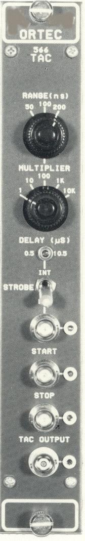
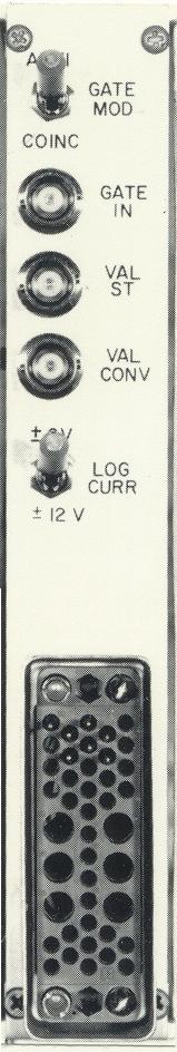
8 2 been adjusted with the front panel TAC Output delay control, 0.5 µs to 10.5 µs after the leading edge of the signal. If the Strobe switch is set at Ext, a signal must be furnished through the Strobe Ext BNC connector to strobe the output promptly. 2. SPECIFICATIONS 2.1. PERFORMANCE TIME RESOLUTION FWHM #0.01% of full scale plus 5 ps for all ranges. TEMPERATURE INSTABILITY #±0.01%/EC (±100 ppm/ec) of full scale or 10 ps/ec (whichever is greater), 0 to 50EC. DIFFERENTIAL NONLINEARITY #±2% from 10 ns to 2% of full scale (whichever is greater) to 100%of full scale. INTEGRAL NONLINEARITY #±0.1% from 10 ns to 2% of full scale (whichever is greater) to 100% of full scale. RESET CYCLE Fixed 1.0 µs for X1 and X10 multipliers; fixed 5 µs for X100 multiplier; and fixed 50 µs for X1k and X10k multipliers. Occurs after Over-range, Strobe cycle, or Ext Strobe Reset cycle. START-TO-STOP CONVERSION TIME Minimum #5 ns FRONT PANEL CONTROLS RANGE (ns) Three-position rotary switch selects full-scale time interval of 50, 100, or 200 ns between accepted Start and Stop input signals. MULTIPLIER Five-position rotary switch extends time range by a multiplying factor of 1, 10, 100, 1k, or 10k. DELAY (µs) 20-turn screwdriver-adjustable potentiometer varies the delay of the TAC output from 0.5 µs to 10.5 µs, relative to an accepted Stop input signal; operable in the Int Strobe mode only. STROBE MODE Two-position locking toggle switch selects either Internal or External source for initiating the strobe cycle to strobe valid information from the TAC output REAR PANEL CONTROLS GATE MODE Two-position locking toggle switch selects Coincidence or Anticoincidence mode of operation for the Start circuitry. Start circuitry is enabled in the Coinc position or inhibited in the Anti position during the interval of a Gate input signal. LOG CURR Two-position locking toggle switch selects the use of ±6 V or ±12 V bin lines to provide current for the internal logic circuitry. In the ±6 V position the 566 is within the current allotment for a single NIM width when using a NIMstandard Class V power supply. In the ±12 V position the 566 exceeds the current allotment for a single NIM width on the +12 V and!12 V bin lines. However, this position allows the 566 to be used with power supplies not providing +6 V and!6v INPUTS All four inputs listed below are dc-coupled, edgetriggered, and printed wiring board (PWB) jumper selectable to accept either negative or positive NIMstandard signals. Input impedance is 50 Ω in the negative position and >1kΩ in the positive position. The threshold is!400 mv in the negative position and +2 V in the positive position. STROBE Front panel BNC connector provides an external means to strobe a valid output signal from the TAC in the Ext Strobe mode. The input signal, exceeding threshold within the Ext Strobe reset interval after the Stop input, initiates the read cycle for the linear gate to the TAC output. Factory-set in the positive input position. Ext Strobe reset interval has a minimum value of!0.5µs and a maximum value of nominally 10 µs. START Front panel BNC connector initiates time conversion when Start input signal exceeds threshold. Factory-set in negative input position. STOP Front panel BNC connector terminates time conversion when Stop input signal exceeds threshold. Factory-set in negative input position.
9 3 GATE IN Rear panel BNC connector provides an external means of gating the Start circuitry in either Coincidence or Anticoincidence with the Start input signal. Gate input signal must cross threshold $10 ns prior to the Start input signal and must overlap the trigger edge of the Start input signal. Factory-set in the positive input position OUTPUTS TAC OUTPUT Front panel BNC connector provides unipolar pulse.! Amplitude 0 V to +10 V proportional to Start/Stop input time difference.! Time End of delay period in Int Strobe mode; prompt with Strobe input in Ext Strobe mode.! Width Adjustable by PWB potentiometer from #l µs to $3 µs.! Impedance Z o < 1Ω.! Rise Time!250 ns.! Fall Time!250 ns. VAL ST Rear panel BNC connector provides NIMstandard slow-positive logic level signal.! Amplitude Nominally +5 V. Complement signal selectable by PWB jumper.! Time and Width From accepted Start input to end of reset.! Impedance Z o < 10Ω.! Rise Time #50 ns.! Fall Time #50 ns. VAL CONV Rear panel BNC connector provides NIM-standard slow-positive logic level signal to indicate a valid conversion.! Amplitude Nominally +5 V. Complement signal selectable by PWB jumper.! Time and Width From end of internal delay after Stop to end of reset.! Impedance Z o < 1 Ω.! Rise Time!250 ns.! Fall Time!250 ns ELECTRICAL AND MECHANICAL POWER REQUIRED (Log Switch)! ±6V +24 V, 45 ma;!24 V, 50 ma; +12 V, 95 ma;!12 V, 140 ma; +6 V, 140 ma;!6 V, 300 ma.! ±12V +24 V, 45 ma;!24 V, 50 ma; +12 V, 210 ma;!12 V, 405 ma. WEIGHT! Net 1.5 kg (3.3 lb).! Shipping 3.0 kg (7.0 lb). DIMENSIONS NIM-standard single-width module cm (1.35 x in.) per TID (Rev). 3. INSTALLATION 3.1. GENERAL The ORTEC 4001 A/4002A, 4001 A/402D, or 4001 C/ 402D Bin and Power Supply (or equivalent), in which the 566 will be installed, is intended for rack mounting. If vacuum tube equipment is operated in the same rack, there must be sufficient cool air circulating to prevent localized heating of the alltransistor circuits in the 566 and in the other modules in the bin and power supply. Rack-mounted equipment subjected to the temperatures in vacuum tube equipment can exceed the maximum for which the transistorized circuits are designed unless this precaution is taken. The 566 should not be subjected to temperatures in excess of 120EF (50EC) CONNECTION TO POWER The 566 is designed per TID and accepts its operating power requirements through a mating power connector when it is installed in an ORTEC 4001A/ 4002A Bin and Power Supply. As a safety precaution, always turn off the power for the bin before inserting or removing any modules. Monitor the dc voltages at the test points on the control panel of the bin after all modules have been installed and the power is turned on in order to determine that none of the four power levels have been reduced by an overload CONNECTION INTO A SYSTEM The 566 can accept both start and stop pulses from NIM modules that furnish NIM-standard positive and fast-negative logic signals or from the timing output of a photomultiplier tube base. Typical ORTEC instruments that provide compatible signals are the 583, 584, and 473A discriminators and the 265, 269, 270, and 271 photomultiplier tube bases. The start and stop inputs will properly terminate 50 Ω
10 4 cable, and this type is recommended to ensure proper termination of the signals. No input or output connectors need be terminated when they are not in use. In any experiment in which it is reasonable to assume that the count rates for start and stop will be equal or nearly equal, use the signal furnished from the origin of events into the start input and the signal furnished from the response into the stop input. The 566 will then measure the time difference (T) from origin to response and furnish an output amplitude that is some fraction of the selected fullscale amplitude, proportional to the ratio of T, to the selected full-scale time range. In any experiment in which the two count rates differ noticeably, such as one in which fewer responses than event origins can be expected, use the lower count rate as the start input to the 566. This assures that the 566 dead time will be minimized because it analyzes the time difference only after a start signal is accepted. When the response is used as a start signal, furnish the signals from the origin of events through a delay line into the stop input, and adjust the delay to match the selected fuii-scale time of the 566. At each start input signal the 566 will analyze the time until its related origin signal is furnished to the stop input. The time measured. is then delay time minus T, and produces a so-called inverted time spectrum. The purpose of this type of system connection is to reduce the number of conversions and the corresponding dead time. during the experiment. For each signal accepted through the start input there must be a conversion, but for each signal through the stop input there need not be a conversion. For each start signal that is not followed by a stop signal within the selected time full range, the converter measures a time equal to the total range, even though no output pulse is generated LINEAR OUTPUT SIGNAL CONNECTIONS AND TERMINATING IMPEDANCE The source of impedance of the standard TAC output, with the 0 to 10 V linear range, is about 1 Ω through the connector on the front panel. For the front panel circuit, the interconnection to other modules does not usually require any special considerations, especially it the interconnecting cable is shorter than 4-ft in length. Paralleling several loads on a single output will still not reduce the 0 to 10 V signal span significantly unless the combined load is <100 Ω. As with any analog instrument, oscillations may be observed occasionally when unterminated lengths of cable are used. Short cable lengths (up to 4 ft) need not be terminated. When longer cable lengths are required for transfer of a linear signal, the cable should be terminated in a resistive load equal to the cable impedance to prevent reflections and oscillations in the cable. Oscillation suppression can be effected by either a series termination at the sending end of the cable or by a shunt termination at the receiving end. For convenience a BNC tee can usually accommodate both the cable and a mating terminator at the input of the receiving instrument. These units ate available commercially, including B.C. terminators with nominal values of 50, 100, and 1000 Ω. ORTEC stocks a limited quantity of all but the 1000 Ω terminators for your convenience, as listed below: B.C. Tee Connector C Ω Terminator C Ω Terminator C-27 When a shunt termination at the receiving end of the cable is impractical, consider series termination at the sending end. For a series termination the full signal amplitude span is available at the receiving end only if the input impedance is many times the characteristic impedance of the cable. For series termination install the correct resistance between the actual amplifier output on the etched circuit board and the output connector. Effectively, the terminating resistance is in series with the input impedance of the receiving instrument, and may result in some loss in signal amplitude. For example, if the series terminator is 93 Ω and the driven load is 900 Ω, the available signal span will be only about 90% of the maximum signal amplitude for each pulse. The termination of a 93-Ω cable in a 93-Ω load will cause!50% loss for the signal LOGIC SIGNAL CONNECTIONS The start and stop input circuits accept positive or negative NIM-standard signals. Each of these input circuits is jumper selectable. Input impedance of 50 Ω for negative signals or >1 kω for positive signals is intended as the proper termination for the signals.
11 5 Impedance considerations for each of the remaining logic inputs and output for the 566 are noncritical and 93-Ω cable is usually used. They can be terminated with 100 Ω to prevent ringing if the signal is used to drive a high-impedance load. 4. OPERATING INSTRUCTIONS 4.1. TIME-TO-AMPLITUDE CONVERSION There are four front panel controls and two rear panel controls on the 566. Of these, four are directly associated with the conversion of a start-to-stop interval into an analog equivalent TAC output pulse. These controls are Range (ns), Multiplier, Delay (µs), and Anti/Coinc. The Range (ns) and Multiplier switches determine the full-scale limit for time conversion. Any of 15 combinations can be selected as follows: Range (ns) Switch Settings Multiplier Full-Scale Time Limit 50 X1 50 ns 100 X1 10 ns 200 X1 200 ns 50 X ns 100 X10 1 µs 200 X10 2 µs 50 X100 5 µs 100 X µs 200 X µs 50 X1k 50 µs 100 X1k 0.1 ms 200 X1k 0.2 ms 50 X10k 0.5 ms 100 X10k 1 ms 200 X10k 2 ms For example, with the Range switch set at 50 and the Multiplier switch at X100, the full-scale time range is 5 µs. Any stop input signal that occurs within 5 µs after a valid-start signal will initiate the gating of an output pulse through the TAC Output connector. The output pulse will not be furnished through this connector unless it is strobed. The strobe condition is selected by a front panel switch. When the output does occur, its peak amplitude will be proportional to the ratio of the measured start-tostop interval to the selected full-scale time in a 0 to 10 V range. Internal logic eliminates any pulse ambiguity. No output pulse is furnished unless a stop signal is accepted within the selected full-range time. A stop signal is not effective unless it is preceded by a valid-start signal. For further logical control either a coincidence or anticoincidence mode can be selected for gating control of the start input circuit. To eliminate gating for the start input, set the Gate Mod switch at Anti/Coin and leave the gate input circuit without any connection. When the same switch setting is used and an input signal is furnished, start signals are not accepted when the gate signal is +2 V or more. For coincidence gating of the start input circuit, set the Gate switch at Coin and furnish a signal of +2 V or more through the Gate logic Input connector when start signals are to be accepted. The front panel Strobe switch selects the source for the strobe signal for the TAC output. When the switch is set at Int, the strobe is generated by a delayed, valid-start signal, and the delay is fixed at a time that is longer than the selected full range time. 5. CIRCUIT DESCRIPTION The jumpers locations and settings discussed in this chapter are depicted in Figs. 3 and 4. Please refer to these figures as you read the circuit description given below. To access the PWB as viewed in these illustrations, remove the right side panel, as viewed from the front panel. The jumpers are located near the bottom edge of the board. The identifiers used in the illustrations are:
12 6 Jumper Identifiers in Fig. 3 SP (J5) STG (J4) ST (J3) STR (J1) VST (J7) VCV (J8) Definition STOP IN START GATE IN START IN EXT STROBE IN VALID START OUT VALID CONV OUT 5.1. START CIRCUITRY The start circuitry is used to generate a logic signal which begins the time-to-amplitude conversion in the 566. Two inputs, the START (front-panel) and the GATE IN (rear-panel) are used to control the start circuitry. The GATE IN allows START signals to be blocked by a user supplied logic signal. The user can select blocking in coincidence or anticoincidence mode via a rear-panel switch. Also, PWB jumpers allow the selection of either positive or negative NIM logic signals for both the START and the GATE IN. The input circuitry for the START and the GATE IN provide for the proper termination of the input signals, level-shifting, and buffering. The START input circuitry consists of Q1, Q2, 1/2 of U1, J3, D4- D6, and associated passive components, while the GATE IN input circuitry includes Q3, Q4, half of U1, J4, D1 -D3, and associated passive components. If the GATE IN signal meets the proper coincidence/ anticoincidence condition selected by the user, an ECL logic true level is set on U2(7), the D input of a dual ECL flip-flop, allowing a START signal to set this flip-flop. The Q output of this flip-flop [U2(2)] sets the other half of U2, place U2(15) in the ECL true state and U2(14) in the ECL false state. These two signals go through level-shifting transistors Q10, Q11, and Ql5, and turn transistor Q17 off. Then, the current which was flowing through Q17 discharges C38 and any other capacitor selected by the front panel MULTIPLIER switch. This discharging will continue until halted by the stop circuitry. The discharge rate of C38 is set by the precision current source comprised of U7, Q29, Dl9, and associated passive components. Both the RANGE switch and the MULTIPLIER switch control the magnitude of this current source. A logic signal is generated on the VALID START output by each start signal which is enabled by the GATE IN. This signal extends from the beginning of the start pulse until the TAC is reset STOP CIRCUITRY The stop circuitry generates a logic signal which ends the time-to-amplitude conversion in the 566. This circuitry is controlled by the front-panel STOP input, and a PWB jumper allows the selection of either a positive or negative NIM logic signal for STOP. The STOP input circuitry is identical to the START input circuitry. When the STOP input becomes active, an EOL flipflop(1/2 of U4) is set. The Q output of this flip-flop sets the other ½ of U4 if a valid START signal has previously set U2(2) to the ECL true state, causing U4(15) to switch to the ECL true state and U4(14) to switch to the ECL false state. These signals propagate through level-shifting transistors Q12, Q13, and Q19 to turn off transistor Q20, terminating the current flow out of C38 and ending the time-toamplitude conversion cycle GATED BASELINE RESTORER The voltage on C38 is buffered by Q21-Q23. The voltage on the emitter of Q23 is held to a quiescent value of 0 V by a gated baseline restorer (BLR) consisting of U8, C29, Q26, Q31, Q32, U5, and associated passive components. In the quiescent state, the gated BLR acts as a high-gain feedback circuit which maintains the output of Q23 at 0 V. However, when a valid START signal is received, an ECL false signal on U5(13) disables U8 which opens the feedback path. The proper dc voltage is maintained throughout the loop, though, since the output voltage of U8 is held on C29. After the START flip-flop is cleared, the BLR circuit is again enabled STROBE CIRCUITRY When the INT position is selected on the STROBE switch, the output signal is gated out by the buffered STOP signal [U5(12)], after a user selected delay time. This delay time is set by the front-panel DELAY potentiometer, which controls the width of the negative-going, TTL logic signal on U10(4). The rising edge of this signal triggers one-shot U15(13), which fires Q41, which opens the linear gate, A4, allowing the output signal to appear at the TAC output.
, which opens the linear gate.")
13 7 If the EXT position is selected on the STROBE switch, the logic signal supplied by the user on the STROBE input will control the timing of the TAC output. Either positive or negative NIM logic can be selected for this input via a PWB jumper. If the EXT mode is selected, the STROBE input triggers oneshot U15(13), which opens the linear gate. The user may allow a time window for the STROBE signal of 10 µs or 100 µs. If a strobe signal does not occur in this time window (time window begins with the STOP signal), the TAC output is not enabled, and the 566 is reset. Fig. 3. Jumper Locations.
14 8 Fig. 4. Jumper Settings (top, all positive; bottom, all negative). 6. MAINTENANCE 6.1. TESTING PERFORMANCE The following test procedures are furnished as a guide during installation and checkout of the 566 TAC. TEST EQUIPMENT The following test equipment is recommended. Each test procedure refers to this list by the unit identification number for the required item(s) of test equipment. An equivalent unit may be substituted for any item in the list, providing that it furnishes the function required for each specific application. 1. Hewlett-Packard 215A Pulse Generator 2. ORTEC MHZ Discriminator 3. ORTEC 416A Gate and Delay Generator 4. ORTEC 425A Nanosecond Delay 5. Photomultiplier tube with scintillator and radiation source 6. ORTEC 449 Log/Lin Ratemeter 7. Tektronix Type 475 Oscilloscope 8. ORTEC 7100, 7150, 7450 Multichannel Analyzer or 918 Multichannel Buffer 9. ORTEC 414A Fast Coincidence 10. ORTEC 444 Gated Biased Amplifier PRELIMINARY PROCEDURES Take the following preliminary steps when the 566 is installed: 1. Check the module visually for possible damage. 2. With the power turned off, install the 566 into a NIM-Standard bin and power supply such as the ORTEC 4001C/4002A. 3. Check the installation for proper mechanical alignment. 4. Switch on ac power and check the dc power voltage levels at test points on the 4001C. BASIC SWITCH SETTINGS Set the 566 controls as follows: Range 50 ns Multiplier 1 Logic Input Anti/Coin Strobe Int.
15 9 CONVERSION TESTS Use the typical test setup shown in Fig. 6.1 and supply a start and stop pair of input signals with known time difference into the 566. Observe the TAC output. Then use the following procedures: selected time range. The testing procedure consists of the following: Fig Test System for Checking Converter Resolution. Fig Test System for Checking Conversion. 1. Adjust the delay for the stop input to 50 ns. 2. Check to see that the full-scale time range is 50 ns x Measure the signal through the TAC Output connector. It should be about 10 V for a 50-ns delay or 5 V for a 25-ns delay. 4. Turn the Range (ns) switch through its 50, 100, and 200 settings and observe the pulse amplitude at each setting; each successive switch position should decrease the pulse amplitude to about half of the amplitude for the previous setting. 5. Return the Range (ns) switch to 50 and set the Multiplier switch at 10. The output amplitude should be reduced to about 1/10 of the reading for step 3. RESOLUTION TESTS See Fig. 6.2 for the typical test setup used for resolution checks. The start and stop pulses used for this test must have fast rise time and be jitter-free. The minimum delay recommended for the stop pulses is 15 ns. The resolution of any scale can be measured with this setup, and the main consideration is that each stop signal delay be within the linear region of the 1. Adjust the delay for the stop input to a basic setting of 30% to 80% of the selected time range. 2. Operate the system and obtain a timing spectrum. Normalize the output amplitude full range for the normally digitized full range of the ADC in the analyzer. 3. After you have accumulated an adequate spectrum to assure statistical accuracy of photopeak measurements (!1000 counts in the peak channel), identify the peak channel number and measure the FWHM channel number limits. Log for reference. 4. Increase the delay for the stop signal by a fixed and known amount. This may be done by switching in a fixed delay line cable (ORTEC 425A) or by careful adjustment of the delay unit controls. The total delay for the stop signal must still be <100% of the selected time full range. 5. Accumulate a spectrum for this measurement of increased time intervals. 6. Observe the relocated photopeak in the timing spectrum and record its peak channel number and its FWHM channel number limits. 7. Subtract the peak channel number in step 3 from the peak channel number in step 6. This is the number of channels that represents the time variation injected at step 4.
16 10 8. Using the formula below, calculate time resolution effective for the established system calibration: t per channel = stop delay increase channel shift 9. With the equation below, calculate the converter resolution using the FWHM channel width from either step 3 or step 7. These widths should be the same at either peak location. Time resolution (FWHM) = FWHM channel width t per channel This resolution is affected adversely by any jitter that may be present in the discriminator and by the resolution of the amplifier. Allowances should be made for these contributions. COUNT RATE TESTS In many applications it is important for a time-to-amplitude converter to handle high count rates, both external and internal. Since the start input is gated internally and the conversion circuits are all direct-coupled, the limit for its external count rate capability is determined solely by the input pulse width, and there are no pileup effects. The limit on the internal count rate is imposed by the conversion and reset process, where the start input is disabled through a converter busy interval following each accepted start signal. A converter busy interval is the measured time plus!7 us for start-stop intervals within the selected time range or is the selected time range plus 4 µs if no stop signal is furnished within the time range. The following test, based on the system connection shown in Fig. 6.3, permits accumulation of a basic timing spectrum for the start-stop input pulses at 60 Hz. As the external count rate for start only is increased by regulating the random pulse generator, the internal pulse rate in the 566 is increased, and a ratemeter will monitor the resulting rate at which the internal capability is impaired. 1. The photomultiplier may be used as a random pulse generator, triggered by a radiation source. Use an initial sensitivity setting above the energy level for a zero output pulse rate. Fig Test System for Checking Count Rate. 3. Select the 0.5 µs time range with the Adjust the system for a timing spectrum accumulated for the 60-Hz input pulses. 5. Decrease the threshold of the discriminator to generate random start signals with no corresponding stop signals. Monitor the random rate with the ratemeter. 6. Observe the timing spectrum as the random input rate is gradually increased. Watch for interference in the accumulated spectrum. DIFFERENTIAL LINEARITY MEASUREMENTS A system for testing differential linearity of the 566 is shown in the block diagram in Fig In this system the random pulse generator is used as the source for start signals, and a pulse generator with a fixed rate is used for stop signals. The measurable time interval between a start and stop is a random value, with equal probability that it will be any time difference up to the periods between the regular stop signals. For an infinite number of TAC outputs the count levels for each channel of the MCA should be equal. After the test has been run long enough to assure statistical accuracy (e.g., >25,000 counts/channel), the spectrum should be similar to those illustrated in Fig Any deviation from a straight line represents a differential nonlinearity, and the percent of deviation is the difference between this count level and the average divided by the average count level. 2. Adjust the delay for the stop input to!0.4 µs.
17 11 Fig Test System for Checking Differential Linearity. 1. Select the 566 time range to be tested. 2. Calculate the maximum stop pulse repetition rate for the selected time range. This should be slightly lower than the reciprocal of the time range. For example, for the 1 µs time range the reciprocal is 1 x 10", and a pulse generator rate of 4 to 5 times 10' should be satisfactory. A lower rate increases the time required to run the test, while a faster rate will reduce the response because of MCA dead time. 3. Operate the system and monitor the dead time meter on the MCA. Regulate the random start rate to cause the MCA dead time to be!10%. 4. Clear the analyzer to zero and operate the system until the average count level stored in each channel is sufficient to ensure statistical accuracy. 5. Compare any nonlinearity indications to the specifications listed in Section 2. Some nonlinearity can be expected in channels in the lower 5% of the MCA range as shown in Fig. 6.5 because of the stop pulse width and the TAC gating time. CHECKING EXTERNAL STROBING MODE The system for checking the external strobing mode is shown in Fig This system can be used to verify the principles of operation of the 566. Fig Differential Linearity for the Indicated Ranges. 1. Set the delay for the stop signal at about 400 ns. 2. Set the 566 time range for 500 ns.

18 12 Fig Test System for Checking External Strobing Mode. 3. Use the internal strobe mode for the 566. Adjust the oscilloscope sweep as required to identify the TAC output pulses. 4. Adjust the delay for the strobe signal >500 ns to ensure that it will occur later than the full time range. 5. Switch the 566 to its external strobe mode and observe the TAC output pulse. It should be identical to the pulse observed in step 3 except for the time at which it occurs. 6. Vary the front panel Delay (µs) and observe that there is no change in the TAC output amplitude but that the output delay follows the strobe delay CORRECTIVE MAINTENANCE Clean the surfaces of the printed circuits, the connectors, and all chassis parts periodically to prevent accumulated dust from forming leakage paths between the circuit components. If the instrument is suspected of malfunctioning, use the performance tests of Section 6.1 to aid verification. When incorrect operation is identified, disconnect the 566 from its position in the system and perform routine diagnostic tests with a pulse generator and an oscilloscope. Use the timing chart in Fig. 6.7 to isolate the problem. CALIBRATION There is one critical calibration and three adjustments that may need to be made. Fig Timing Chart. CONVERSION CURRENT ADJUST Potentiometer R128, located on the PWB adjusts the conversion current. Using the typical setup shown in Fig. 6.1, follow the setup procedures outlined in "Conversion Tests" steps 1 through 3. Adjust potentiometer R128 counterclockwise to minimum. If the TAC is functioning properly, a pulse output of!8.5 to 9.8 V should be present on the oscilloscope. If this voltage is not present on the oscilloscope, refer to Section 6.3, "Troubleshooting," or return the unit to the ORTEC factory for repair as outlined in Section 6.4. If a pulse is present at the TAC output, the conversion current can be calibrated by adjusting R128 clockwise (slowly) until the output pulse obtains an amplitude of +10 V and begins to half-fire. Adjust R128 counterclockwise (slightly) until the pulse is solid or full-firing.
19 13 OUTPUT WIDTH ADJUSTMENT Potentiometer R163, located on the PWB, adjusts the TAC output pulse width. The potentiometer should vary the output pulse width from 1 µs to 3 µs. The width can be adjusted to customer requirements; factory-set at!2 µs. OUTPUT OFFSET CALIBRATION Potentiometer R223, located on the PWB, adjusts the TAC output offset from!100 mv to +100 mv. Remove the start and stop signals from the TAC input. Measure the offset voltage at the TAC output connector with a voltmeter. Adjust potentiometer R223 until the offset voltage is 0 mv ± 1 mv. Capacitor C93, located on the PWB, is used to filter out any linear gate signals from the TAC output pulse. This is factory-set and should not need further adjustment TROUBLESHOOTING Use the tests in Section 6.1 and the circuit description in Section FACTORY REPAIR This instrument can be returned to the ORTEC factory for service and repair at a nominal cost. Our standard procedure for repair ensures the same quality control and checkout that are used for a new instrument. Always contact our Global Service Center at ORTEC, (865) , before sending in an instrument for repair to obtain shipping instructions and so that the required Return Authorization Number can be assigned to the unit. Write this number on the address label and on the package to ensure prompt attention when it reaches the ORTEC factory.
20 14 Block Diagram of the Model 566 Time-to-Amplitude Converter.
21 15 Bin/Module Connector Pin Assignments For Standard Nuclear Instrument Modules per DOE/ER-0457T. Pin Function Pin Function 1 +3 V 23 Reserved 2-3 V 24 Reserved 3 Spare bus 25 Reserved 4 Reserved bus 26 Spare 5 Coaxial 27 Spare 6 Coaxial * V 7 Coaxial *29-24 V V dc 30 Spare bus 9 Spare 31 Spare V 32 Spare 11-6 V * V ac (hot) 12 Reserved bus *34 Power return ground 13 Spare 35 Reset (Scaler) 14 Spare 36 Gate 15 Reserved 37 Reset (Auxiliary) * V 38 Coaxial *17-12 V 39 Coaxial 18 Spare bus 40 Coaxial 19 Reserved bus * V ac (neutral) 20 Spare *42 High-quality ground 21 Spare G Ground guide pin 22 Reserved Pins marked (*) are installed and wired in ORTEC s 4001A and 4001C Modular System
22 16
Model 9302 Amplifier-Discriminator Operating and Service Manual
 Model 9302 Amplifier-Discriminator Operating and Service Manual Printed in U.S.A. ORTEC Part No. 733690 1202 Manual Revision C Advanced Measurement Technology, Inc. a/k/a/ ORTEC, a subsidiary of AMETEK,
Model 863 Quad Timing Filter Amplifier Operating and Service Manual
 Model 863 Quad Timing Filter Amplifier Operating and Service Manual Printed in U.S.A. ORTEC Part No. 733960 0411 Manual Revision C Advanced Measurement Technology, Inc. a/k/a/ ORTEC, a subsidiary of AMETEK,
Model 533 Dual Sum and Invert Amplifier Operating and Service Manual
 Model 533 Dual Sum and Invert Amplifier Operating and Service Manual Printed in U.S.A. ORTEC Part No. 733410 1202 Manual Revision B Advanced Measurement Technology, Inc. a/k/a/ ORTEC, a subsidiary of AMETEK,
Model 416A Gate and Delay Generator Operating and Service Manual
 Model 416A Gate and Delay Generator Operating and Service Manual Printed in U.S.A. ORTEC Part No. 733160 1202 Manual Revision E Advanced Measurement Technology, Inc. a/k/a/ ORTEC, a subsidiary of AMETEK,
Model 113 Scintillation Preamplifier Operating and Service Manual
 Model 113 Scintillation Preamplifier Operating and Service Manual Printed in U.S.A. ORTEC Part No. 717560 1202 Manual Revision B Advanced Measurement Technology, Inc. a/k/a/ ORTEC, a subsidiary of AMETEK,
Model 427A Delay Amplifier Operating and Service Manual
 Model 427A Delay Amplifier Operating and Service Manual This manual Applies to instruments marked Rev 22" on rear panel Printed in U.S.A. ORTEC Part No. 733210 1202 Manual Revision B Advanced Measurement
Model 9305 Fast Preamplifier Operating and Service Manual
 Model 9305 Fast Preamplifier Operating and Service Manual This manual applies to instruments marked Rev 03" on rear panel. Printed in U.S.A. ORTEC Part No.605540 1202 Manual Revision B Advanced Measurement
Model 426 Linear Gate Operating and Service Manual
 Model 426 Linear Gate Operating and Service Manual This manual applies to instruments marked Rev 23" on rear panel Printed in U.S.A. ORTEC Part No. 733200 1202 Manual Revision B Advanced Measurement Technology,
Model 542 Linear Gate and Stretcher Operating and Service Manual
 Model 542 Linear Gate and Stretcher Operating and Service Manual NOTE: A substitution for the dual diode package (MSD6100) may have been made in this unit. If so, two 1N4153 diodes were used to replace
Model 449 Log/Lin Ratemeter Operating and Service Manual
 Model 449 Log/Lin Ratemeter Operating and Service Manual Printed in U.S.A. ORTEC Part No. 733270 1202 Manual Revision D Advanced Measurement Technology, Inc. a/k/a/ ORTEC, a subsidiary of AMETEK, Inc.
ScintiPack Model 296 Photomultiplier Base with Preamplifier and High Voltage Power Supply Operating and Service Manual
 ScintiPack Model 296 Photomultiplier Base with Preamplifier and High Voltage Power Supply Operating and Service Manual WARNING This equipment generates, uses, and can radiate radio frequency energy, and
Model 439 Digital Current Integrator Operating Manual
 Model 439 Digital Current Integrator Operating Manual Printed in U.S.A. ORTEC Part No. 733240 0908 Manual Revision K Advanced Measurement Technology, Inc. a/k/a/ ORTEC, a subsidiary of AMETEK, Inc. WARRANTY
Model 428 Detector Bias Supply Operating and Service Manual
 Model 428 Detector Bias Supply Operating and Service Manual Printed in U.S.A. ORTEC Part No. 733220 1202 Manual Revision C Advanced Measurement Technology, Inc. a/k/a/ ORTEC, a subsidiary of AMETEK, Inc.
Model 935 Quad Constant-Fraction 200-MHz Discriminator Operating and Service Manual
 Model 935 Quad Constant-Fraction 200-MHz Discriminator Operating and Service Manual U.S. Patent No. 4,179,644 Printed in U.S.A. ORTEC Part No. 753770 0503 Manual Revision H ii $GYDQFHG0HDVXUHPHQW7HFKQRORJ\,QF
Model 480 Pulser Operating and Service Manual
 Model 480 Pulser Operating and Service Manual Printed in U.S.A. ORTEC Part No. 733390 1202 Manual Revision B Advanced Measurement Technology, Inc. a/k/a/ ORTEC, a subsidiary of AMETEK, Inc. WARRANTY ORTEC*
Model 9307 pico-timing Discriminator Operating and Service Manual
 Model 9307 pico-timing Discriminator Operating and Service Manual Printed in U.S.A. ORTEC Part No. 764020 1202 Manual Revision C Advanced Measurement Technology, Inc. a/k/a/ ORTEC, a subsidiary of AMETEK,
Model 276L Low-Power Photomultiplier Base Operating and Service Manual
 Model 276L Low-Power Photomultiplier Base Operating and Service Manual Printed in U.S.A. ORTEC Part No. 762870 0702 Manual Revision C $GYDQFHG 0HDVXUHPHQW 7HFKQRORJ\,QF a/k/a/ ORTEC, a subsidiary of AMETEK,
Model 673 Spectroscopy Amplifier and Gated Integrator Operating and Service Manual
 Model 673 Spectroscopy Amplifier and Gated Integrator Operating and Service Manual Printed in U.S.A. ORTEC Part No. 675590 0202 Manual Revision B $GYDQFHG 0HDVXUHPHQW 7HFKQRORJ\,QF a/k/a/ ORTEC, a subsidiary
Model 2145 Time to Amplitude Converter
 9231617B Model 2145 Time to Amplitude Converter User s Manual Copyright 2005, Canberra Industries, Inc. All rights reserved. The material in this document, including all information, pictures, graphics
Model 142AH Preamplifier Operating and Service Manual
 Model 142AH Preamplifier Operating and Service Manual Printed in U.S.A. ORTEC Part No. 733990 0202 Manual Revision B $GYDQFHG 0HDVXUHPHQW 7HFKQRORJ\,QF a/k/a/ ORTEC, a subsidiary of AMETEK, Inc. WARRANTY
INSTRUCTION MANUAL. March 11, 2003, Revision 3
 INSTRUCTION MANUAL Model 701A Stimulator March 11, 2003, Revision 3 Copyright 2003 Aurora Scientific Inc. Aurora Scientific Inc. 360 Industrial Parkway S., Unit 4 Aurora, Ontario, Canada L4G 3V7 Tel: 1-905-727-5161
Model 7000 Low Noise Differential Preamplifier
 Model 7000 Low Noise Differential Preamplifier Operating Manual Service and Warranty Krohn-Hite Instruments are designed and manufactured in accordance with sound engineering practices and should give
LUDLUM MODEL MODEL AND MODEL GAMMA SCINTILLATORS. June 2017
 LUDLUM MODEL 44-20 MODEL 44-20-1 AND MODEL 44-20-3 GAMMA SCINTILLATORS June 2017 LUDLUM MODEL 44-20 MODEL 44-20-1 AND MODEL 44-20-3 GAMMA SCINTILLATORS June 2017 STATEMENT OF WARRANTY Ludlum Measurements,
Analog-to-Digital-Converter User Manual
 7070 Analog-to-Digital-Converter User Manual copyright FAST ComTec GmbH Grünwalder Weg 28a, D-82041 Oberhaching Germany Version 2.0, July 7, 2005 Software Warranty FAST ComTec warrants proper operation
Model 855 Dual Spectroscopy Amplifier Operating and Service Manual
 Model 855 Dual Spectroscopy Amplifier Operating and Service Manual This manual applies to instruments marked Rev. 03" on rear panel. Printed in U.S.A. ORTEC Part No. 717490 0406 Manual Revision C $GYDQFHG0HDVXUHPHQW7HFKQRORJ\,QF
Model 460 Delay Line Amplifier Operating and Service Manual
 Model 460 Delay Line Amplifier Operating and Service Manual Printed in U.S.A. ORTEC Part No. 733320 1202 Manual Revision C Advanced Measurement Technology, Inc. a/k/a/ ORTEC, a subsidiary of AMETEK, Inc.
2001A. 200KHz Function Generator Instruction Manual. 99 Washington Street Melrose, MA Phone Toll Free
 2001A 200KHz Function Generator Instruction Manual 99 Washington Street Melrose, MA 02176 Phone 781-665-1400 Toll Free 1-800-517-8431 Visit us at www.testequipmentdepot.com WARRANTY Global Specialties
PCO-7114 Laser Diode Driver Module Operation Manual
 PCO-7114 Laser Diode Driver Module Operation Manual Directed Energy, Inc. 1609 Oakridge Dr., Suite 100, Fort Collins, CO 80525, (970) 493-1901 sales@ixyscolorado.com www.ixyscolorado.com Manual Document
BC145 SIGNAL ISOLATOR BOARD
 BC145 SIGNAL ISOLATOR BOARD 4/17 Installation & Operating Manual MN1373 Any trademarks used in this manual are the property of their respective owners. Important: Be sure to check www.baldor.com to download
Directed Energy, Inc Oakridge Dr., Suite 100, Fort Collins, CO
 PCO-7121 Laser Diode Driver Module Operation Manual Directed Energy, Inc. 1609 Oakridge Dr., Suite 100, Fort Collins, CO 80525 sales@ixyscolorado.com www.ixyscolorado.com Contents Contents... 3 Safety...
Model 2126 Constant Fraction Discriminator
 9231701B Model 2126 Constant Fraction Discriminator User s Manual Copyright 2005, Canberra Industries, Inc. All rights reserved. The material in this document, including all information, pictures, graphics
Dual 500ns ADC User Manual
 7072 Dual 500ns ADC User Manual copyright FAST ComTec GmbH Grünwalder Weg 28a, D-82041 Oberhaching Germany Version 2.3, May 11, 2009 Copyright Information Copyright Information Copyright 2001-2009 FAST
Current Probes. User Manual
 Current Probes User Manual ETS-Lindgren Inc. reserves the right to make changes to any product described herein in order to improve function, design, or for any other reason. Nothing contained herein shall
Model 3102D 0-2 kv H.V. Power Supply
 Features Compact single width NIM package Regulated up to ±2000 V dc. 1 ma output Noise and ripple 3 mv peak to peak Overload and short circuit protected Overload, inhibit and polarity status indicators
Glass Electrode Meter
 Glass Electrode Meter INSTRUCTION MANUAL FOR Glass Electrode R/C Meter MODEL 2700 Serial # Date PO Box 850 Carlsborg, WA 98324 U.S.A. 360-683-8300 800-426-1306 FAX: 360-683-3525 http://www.a-msystems.com
NANOSECOND PULSE GENERATOR NPG-18/3500(N) USER MANUAL
 USER MANUAL") NANOSECOND PULSE GENERATOR NPG-18/3500(N) USER MANUAL 2014 Megaimpulse Ltd. Copyright 2013 MEGAIMPULSE Ltd. All Rights Reserved. MEGAIMPULSE LTD. PROVIDES THIS MANUAL "AS IS" WITHOUT WARRANTY OF ANY KIND,
NANOSECOND PULSE GENERATOR NPG-18/3500(N) USER MANUAL 2014 Megaimpulse Ltd. Copyright 2013 MEGAIMPULSE Ltd. All Rights Reserved. MEGAIMPULSE LTD. PROVIDES THIS MANUAL "AS IS" WITHOUT WARRANTY OF ANY KIND,
P5100A & P5150 High Voltage Probes Performance Verification and Adjustments
 x P5100A & P5150 High Voltage Probes Performance Verification and Adjustments ZZZ Technical Reference *P077053001* 077-0530-01 xx P5100A & P5150 High Voltage Probes Performance Verification and Adjustments
Model 305 Synchronous Countdown System
 Model 305 Synchronous Countdown System Introduction: The Model 305 pre-settable countdown electronics is a high-speed synchronous divider that generates an electronic trigger pulse, locked in time with
201AP Charge Amplifier User Manual
 Trig-Tek 201AP Charge Amplifier User Manual Publication No. 980996 Rev. A Astronics Test Systems Inc. 4 Goodyear, Irvine, CA 92618 Tel: (800) 722-2528, (949) 859-8999; Fax: (949) 859-7139 atsinfo@astronics.com
AMP-13 OPERATOR S MANUAL
 AMP-13 OPERATOR S MANUAL Version 2.0 Copyright 2008 by Vatell Corporation Vatell Corporation P.O. Box 66 Christiansburg, VA 24068 Phone: (540) 961-3576 Fax: (540) 953-3010 WARNING: Read instructions carefully
MODEL 5002 PHASE VERIFICATION BRIDGE SET
 CLARKE-HESS COMMUNICATION RESEARCH CORPORATION clarke-hess.com MODEL 5002 PHASE VERIFICATION BRIDGE SET TABLE OF CONTENTS WARRANTY i I BASIC ASSEMBLIES I-1 1-1 INTRODUCTION I-1 1-2 BASIC ASSEMBLY AND SPECIFICATIONS
CT-2 and CT-3 Channel Taggers OPERATION MANUAL
 CT-2 and CT-3 Channel Taggers OPERATION MANUAL Trilithic Company Profile Trilithic is a privately held manufacturer founded in 1986 as an engineering and assembly company that built and designed customer-directed
4413 UPDATING PROGRAMMABLE DISCRIMINATOR 4415A NON-UPDATING PROGRAMMABLE DISCRIMINATOR
 TECHNICAL DATA 4413 UPDATING PROGRAMMABLE DISCRIMINATOR 4415A NON-UPDATING PROGRAMMABLE DISCRIMINATOR CAMAC Packaging 16 Inputs Per Module ECLine Compatible Adjustable Output Widths Remote or Local Threshold
Advanced Test Equipment Rentals ATEC (2832)
") Established 1981 Advanced Test Equipment Rentals www.atecorp.com 800-404-ATEC (2832) A.H. Systems Model Active Monopole Antennas Active Monopole Antenna Series Operation Manual 1 TABLE OF CONTENTS INTRODUCTION
Established 1981 Advanced Test Equipment Rentals www.atecorp.com 800-404-ATEC (2832) A.H. Systems Model Active Monopole Antennas Active Monopole Antenna Series Operation Manual 1 TABLE OF CONTENTS INTRODUCTION
Operation and Service Manual. 350 MHz Preamplifier SIM914. Stanford Research Systems
 Operation and Service Manual Stanford Research Systems Revision 1.8 August 24, 2006 Certification Stanford Research Systems certifies that this product met its published specifications at the time of shipment.
200B Clipper Module User Manual
 Trig-Tek 200B Clipper Module User Manual Publication No. 980954 Rev. A Astronics Test Systems Inc. 4 Goodyear, Irvine, CA 92618 Tel: (800) 722-2528, (949) 859-8999; Fax: (949) 859-7139 atsinfo@astronics.com
HP 86290B RF PLUG-IN GHz HEWLETT PACKARD
 OPERATING AND SERVICE MANUAL. HP 86290B RF PLUG-IN 2.0-18.6 GHz HEWLETT PACKARD COPYRIGHT AND DISCLAIMER NOTICE Copyright - Agilent Technologies, Inc. Reproduced with the permission of Agilent Technologies
Model Hz to 10MHz Precision Phasemeter. Operating Manual
 Model 6610 1Hz to 10MHz Precision Phasemeter Operating Manual Service and Warranty Krohn-Hite Instruments are designed and manufactured in accordance with sound engineering practices and should give long
VT1586A Rack Mount Terminal Panel Installation and User s Manual
 VT1586A Rack Mount Terminal Panel Installation and User s Manual Manual Part Number: 82-0095-000 Rev. June 16, 2003 Printed in U.S.A. Certification VXI Technology, Inc. certifies that this product met
CLEANING CALIBRATION INTERVAL
 &DUHDQG0DLQWHQDQFH! &DUHDQG0DLQWHQDQFH CLEANING CALIBRATION INTERVAL SERVICE STRATEGY TROUBLESHOOTING A. Trace Off Scale The exterior of the probe and cable should be cleaned only using a soft cloth moistened
Instruction Manual CT-6 High Frequency AC Current Probe
 Instruction Manual CT-6 High Frequency AC Current Probe 071-0453-00 Revision A Copyright Tektronix, Inc. All rights reserved. Tektronix products are covered by U.S. and foreign patents, issued and pending.
Broadband Step-Up Transformer. User Manual
 Broadband Step-Up Transformer User Manual 990-1930 09/2004 Introduction Introduction About this unit The APC Step-Up Transformer provides 220 V power from 60 VAC Broadband cable systems. Safety Electrical
Model 1791 VHF Radio User's Manual
 Model 79 VHF Radio User's Manual ALL WEATHER INC 65 NATIONAL DRIVE SACRAMENTO, CA 95834 WWW.ALWEATHERINC.COM 79 VHF RADIO USER'S MANUAL CONTENTS INTRODUCTION... Description... Transmitter Module... Power
NANOSECOND PULSE GENERATOR NPG-15/2000(N) USER MANUAL
 USER MANUAL") NANOSECOND PULSE GENERATOR NPG-15/2000(N) USER MANUAL 2013 Megaimpulse Ltd. Copyright 2013 MEGAIMPULSE Ltd. All Rights Reserved. MEGAIMPULSE LTD. PROVIDES THIS MANUAL "AS IS" WITHOUT WARRANTY OF ANY KIND,
NANOSECOND PULSE GENERATOR NPG-15/2000(N) USER MANUAL 2013 Megaimpulse Ltd. Copyright 2013 MEGAIMPULSE Ltd. All Rights Reserved. MEGAIMPULSE LTD. PROVIDES THIS MANUAL "AS IS" WITHOUT WARRANTY OF ANY KIND,
Amptek sets the New State-of-the-Art... Again! with Cooled FET
 Amptek sets the New State-of-the-Art... Again! with Cooled FET RUN SILENT...RUN FAST...RUN COOL! Performance Noise: 670 ev FWHM (Si) ~76 electrons RMS Noise Slope: 11.5 ev/pf High Ciss FET Fast Rise Time:
CIRCUIT-TEST ELECTRONICS
 USER'S MANUAL Sweep Function Generator with Counter SWF-8030 CIRCUIT-TEST ELECTRONICS www.circuittest.com TABLE OF CONTENTS SAFETY INFORMATION...page 3 INTRODUCTION... 4 SPECIFICATIONS... 5 FRONT PANEL
CSM-S USER S MANUAL TRIGGER DISTRIBUTION MODULE Release April 7, VXI Technology, Inc.
 CSM-S-11056 TRIGGER DISTRIBUTION MODULE USER S MANUAL 82-0051-000 Release April 7, 2003 VXI Technology, Inc. 2031 Main Street Irvine, CA 92614-6509 (949) 955-1894 bus 2 VXI Technology, Inc. www.vxitech.com
Current Probe Fixture Instruction Manual
 Current Probe Fixture Instruction Manual 1 TABLE OF CONTENTS INTRODUCTION 3 GENERAL INFORMATION 4 TEST METHODS 5 SAFETY 7 FIGURES 8 FORMULAS 10 MAINTENANCE 11 WARRANTY 12 2 INTRODUCTION figure 1 Mechanical
PLL Synchronizer User s Manual / Version 1.0.6
 PLL Synchronizer User s Manual / Version 1.0.6 AccTec B.V. Den Dolech 2 5612 AZ Eindhoven The Netherlands phone +31 (0) 40-2474321 / 4048 e-mail AccTecBV@tue.nl Contents 1 Introduction... 3 2 Technical
TRANSDUCER IN-LINE AMPLIFIER
 TRANSDUCER IN-LINE Voltage Model AMPLIFIER 2080 Arlingate, Columbus, Ohio 43228, (614) 850-5000 Sensotec, Inc. 2080 Arlingate Lane Columbus, Ohio 43228 Copyright 1995 by Sensotec, Inc. all rights reserved
OPERATION & SERVICE MANUAL FOR FC 110 AC POWER SOURCE
 OPERATION & SERVICE MANUAL FOR FC 100 SERIES AC POWER SOURCE FC 110 AC POWER SOURCE VERSION 1.3, April 2001. copyright reserved. DWG No. FC00001 TABLE OF CONTENTS CHAPTER 1 INTRODUCTION... 1 1.1 GENERAL...
Wilcom MODEL T136BSBZW CIRCUIT TEST SET. Operating Instructions
 Wilcom MODEL T136BSBZW CIRCUIT TEST SET Operating Instructions T136BSB Current Test Set Operating Instructions 811-230-007 February 2007 Copyright (c) 2007 Wilcom All Rights reserved Wilcom reserves the
SRVODRV REV7 INSTALLATION NOTES
 SRVODRV-8020 -REV7 INSTALLATION NOTES Thank you for purchasing the SRVODRV -8020 drive. The SRVODRV -8020 DC servo drive is warranted to be free of manufacturing defects for 1 year from the date of purchase.
Signal Forge 1800M Frequency Expansion Module. 1.0 GHz to 1.8 GHz. User Manual
 TM TM Signal Forge 1800M Frequency Expansion Module 1.0 GHz to 1.8 GHz User Manual Technical Support Email: Support@signalforge.com Phone: 512.275.3733 x2 Contact Information Web: www.signalforge.com
305 Stimulus Isolator. Description
 Description The Model 305 Stimulus Isolator utilizes photon coupling to provide nearly ideal isolation of the pulse and train outputs of the WPI Series 300 Anapulse Stimulators. Two Model 305 units are
P5100A & P5150 High Voltage Probes Performance Verification and Adjustments
 x P5100A & P5150 High Voltage Probes Performance Verification and Adjustments ZZZ Technical Reference *P077053002* 077-0530-02 xx P5100A & P5150 High Voltage Probes Performance Verification and Adjustments
OPERATING AND MAINTENANCE MANUAL
 5Hz to 1MHz WIDE RANGE FULLY AUTOMATIC DISTORTION ANALYZER MODEL 6900B SERIAL NO. OPERATING AND MAINTENANCE MANUAL Unit 4, 15 Jonathan Drive, Brockton, MA 02301-5566 Tel: (508) 580-1660; Fax: (508) 583-8989
DUAL CHANNEL BROADBAND LINEAR AMPLIFIER Model A800D
 DUAL CHANNEL BROADBAND LINEAR AMPLIFIER Model A800D HIGH VOLTAGE FIXED GAIN BROADBAND 800Vpp 60mA 100x DC to ca 200 khz LOW OUTPUT IMPEDANCE HIGH SLEW RATE
12-Bit Successive-Approximation Integrated Circuit A/D Converter AD ADC80
 a 2-Bit Successive-Approximation Integrated Circuit A/D Converter FEATURES True 2-Bit Operation: Max Nonlinearity.2% Low Gain T.C.: 3 ppm/ C Max Low Power: 8 mw Fast Conversion Time: 25 s Precision 6.3
PARALLEL MULTI-AMP KIT for 7200 Series AMPLIFIERS INSTRUCTION SHEET
 2 5 0 7 W a r r e n S t r e e t, E l k h a r t, I N 4 6 5 1 6 U S A 5 7 4. 2 9 5. 9 4 9 5 w w w. A E T e c h r o n. c o m PARALLEL MULTI-AMP KIT for 7200 Series AMPLIFIERS INSTRUCTION SHEET Kit Contents:
Independent Technology Service Inc Independence Ave. Chatsworth, California Toll Free:
 Independent Technology Service Inc. 9182 Independence Ave. Chatsworth, California 91311 www.itscnc.com Toll Free: 1.800.342.3475 NEW Brush Amplifiers For Fadal Machines AMP-0006N-ITS AMP-0021N-ITS NEW
P7313SMA 13 GHz Differential Probe
 x P7313SMA 13 GHz Differential Probe ZZZ Technical Reference *P077196802* 077-1968-02 xx P7313SMA 13 GHz Differential Probe ZZZ Technical Reference www.tektronix.com 077-1968-02 Copyright Tektronix. All
Model 5100F. Advanced Test Equipment Rentals ATEC (2832) OWNER S MANUAL RF POWER AMPLIFIER
 OWNER S MANUAL RF POWER AMPLIFIER") Established 1981 Advanced Test Equipment Rentals www.atecorp.com 800-404-ATEC (2832) OWNER S MANUAL Model 5100F RF POWER AMPLIFIER 0.8 2.5 GHz, 25 Watts Ophir RF 5300 Beethoven Street Los Angeles, CA 90066
Established 1981 Advanced Test Equipment Rentals www.atecorp.com 800-404-ATEC (2832) OWNER S MANUAL Model 5100F RF POWER AMPLIFIER 0.8 2.5 GHz, 25 Watts Ophir RF 5300 Beethoven Street Los Angeles, CA 90066
User s Guide. RP7000 Series Active Probe. Dec RIGOL Technologies, Inc.
 User s Guide RP7000 Series Active Probe Dec. 2012 RIGOL Technologies, Inc. Guaranty and Declaration Copyright 2011 RIGOL Technologies, Inc. All Rights Reserved. Trademark Information RIGOL is a registered
SUBNANOSECOND PULSE GENERATOR PPG-2/1000 USER MANUAL
 SUBNANOSECOND PULSE GENERATOR PPG-2/1000 USER MANUAL 2015 Megaimpulse Ltd. Copyright 2015 MEGAIMPULSE Ltd. All Rights Reserved. MEGAIMPULSE LTD. PROVIDES THIS MANUAL "AS IS" WITHOUT WARRANTY OF ANY KIND,
2015 RIGOL TECHNOLOGIES, INC.
 Service Guide DG000 Series Dual-channel Function/Arbitrary Waveform Generator Oct. 205 TECHNOLOGIES, INC. Guaranty and Declaration Copyright 203 TECHNOLOGIES, INC. All Rights Reserved. Trademark Information
Model 310H Fast 800V Pulse Generator
 KEY FEATURES Temperature Stability +/-5ppm 100 V to 800 V into 50 Ω
Wilcom MODEL T136BGMZW CIRCUIT TEST SET. Operating Instructions
 Wilcom MODEL T136BGMZW CIRCUIT TEST SET Operating Instructions T136BGM Current Test Set Operating Instructions 811-233-010 February 2007 Copyright (c) 2007 Wilcom All Rights reserved Wilcom reserves the
DC200A Displacement Clipper User Manual
 Trig-Tek DC200A Displacement Clipper User Manual Publication No. 980981 A Inc. 4 Goodyear, Irvine, CA 92618 Tel: (800) 722-2528, (949) 859-8999; Fax: (949) 859-7139 atsinfo@astronics.com atssales@astronics.com
SI-125 Power Amplifier Manual 6205 Kestrel Road; Mississauga, Ontario; Canada; L5T 2A1 November 2016, Rev 0.5
 SI-125 Power Amplifier Manual 6205 Kestrel Road; Mississauga, Ontario; Canada; L5T 2A1 November 2016, Rev 0.5 Phone: (905) 564-0801 Fax: (905) 564-0806 www.telecor.com E:\T2-108\T2-M108-ABC\T2-M108-B.doc/AD
DA560D COMPACT SERIES. INSTALLATION / OWNER'S MANUAL Mobile Power Amplifiers
 DA560D COMPACT SERIES INSTALLATION / OWNER'S MANUAL Mobile Power Amplifiers Preparation Please read entire manual before installation. Due to the technical nature of amplifiers, it is highly recommended
Log Periodic Antenna
 Page 1 of 10 Log Periodic Antenna ALFM 80120 88 MHz to 108 MHz (Extendible to 80 to 120 MHz) Page 2 of 10 Table of Contents 1.0 Introduction... 3 2.0 Product Specifications... 4 3.0 Important Safety Precautions...
LeCroy Research Systems Model 365AL, Model 465, and Model 622 Logic Units
 Page 1 of 5 365AL DUAL 4-FOLD MAJORITY LOGIC UNIT 465 TRIPLE 4-FOLD LOGIC UNIT (Note - the 465 is no longer available) 622 QUAD 2 LOGIC UNIT NIM Packaging High Speed Multiple Input Multiple Output Selectable
40 Amp Digital Bidirectional PWM Motor Controller with Regenerative Braking BIDIR-340-DR
 40 Amp Digital Bidirectional PWM Motor Controller with Regenerative Braking BIDIR-340-DR The BIDIR-340-DR is a fully solid-state motor controller that allows you to control the speed and direction of a
User Instructions. Model PS-2001L. Power Supply. Model SPS Power Supply. Audiocom Intercom Systems Rev. A, 4/2001.
 User Instructions PS-00L Model PS-00L Power Supply SPS-00 Volume Model SPS-00 Power Supply Audiocom Intercom Systems 950-7699-000 Rev. A, /00 FCC Statement This equipment uses, and can radiate radio frequency
AMP-12 OPERATOR S MANUAL
 AMP-12 OPERATOR S MANUAL Version 1.0 Copyright 2002 by Vatell Corporation Vatell Corporation P.O. Box 66 Christiansburg, VA 24068 Phone: (540) 961-3576 Fax: (540) 953-3010 WARNING: Read instructions carefully
TK 100 Probe Calibrator. Instruction Manual
 TK 100 Probe Calibrator Instruction Manual Copyright 2013 PMK GmbH All rights reserved. Information in this publication supersedes that in all previously published material. Specifications are subject
INSTRUMENTS, INC. Models 2960AR and 2965AR Disciplined Rubidium Frequency Standards. Section Page Contents
 INSTRUMENTS, INC. Models 2960AR and 2965AR Disciplined Rubidium Frequency Standards 2960AR 2965AR Section Page Contents 1.0............................. 2......................... Description 2.0.............................
742A Series Resistance Standards
 742A Series Resistance Standards Instruction Manual PN 850255 September 1988 Rev. 1, 4/89 1988-2015 Fluke Corporation. All rights reserved. All product names are trademarks of their respective companies.
Signal Forge 2500M Frequency Expansion Module. 1.5 GHz to 2.6 GHz. User Manual
 TM TM Signal Forge 2500M Frequency Expansion Module 1.5 GHz to 2.6 GHz User Manual Technical Support Email: Support@signalforge.com Phone: 512.275.3733 x2 Contact Information Web: www.signalforge.com Sales
DA604D DA954D DA501D DA801D COMPACT SERIES. INSTALLATION / OWNER'S MANUAL Mobile Power Amplifiers
 DA604D DA954D DA501D DA801D COMPACT SERIES INSTALLATION / OWNER'S MANUAL Mobile Power Amplifiers Preparation Please read entire manual before installation. Due to the technical nature of amplifiers, it
34134A AC/DC DMM Current Probe. User s Guide. Publication number April 2009
 User s Guide Publication number 34134-90001 April 2009 For Safety information, Warranties, Regulatory information, and publishing information, see the pages at the back of this book. Copyright Agilent
DUAL%CHANNEL%LINEAR%AMPLIFIER %WITH%PHASE%INVERTER Model&A400DI
 ELECTRONICS AB DUAL%CHANNEL%LINEAR%AMPLIFIER %WITH%PHASE%INVERTER ModelA400DI HIGHVOLTAGE FIXEDGAIN BROADBAND ±200V 150mA 20x DCtoca500kHz FULLSCALE LOWOUTPUTIMPEDANCE HIGHSLEWRATE
Broadband Current Probe Series Operation Manual
 Broadband Current Probe Series Operation Manual 1 TABLE OF CONTENTS INTRODUCTION 3 GENERAL INFORMATION 4 OPERATING INSTRUCTIONS 5 FORMULAS 6 MAINTENANCE 7 WARRANTY 8 2 INTRODUCTION CURRENT PROBE SPECIFICATIONS
INSTRUMENTS, INC. Model 2960AX Disciplined Quartz Frequency Standard 2960AX. Section Page Contents
 INSTRUMENTS, INC. Model 2960AX Disciplined Quartz Frequency Standard 2960AX Section Page Contents 1.0............................. 2......................... Description 2.0.............................
DA6002D-DA10004D. INSTALLATION / OWNER'S MANUAL Mobile Power Amplifiers
 DA6002D-DA10004D INSTALLATION / OWNER'S MANUAL Mobile Power Amplifiers Preparation Please read entire manual before installation. Due to the technical nature of amplifiers, it is highly recommended that
Reconfigurable Laser Servo
 Reconfigurable Laser Servo, Inc. www.vescentphotonics.com 4865 E. 41st Ave Denver, CO 80216 Phone: (303)-296-6766 Fax: (303)-296-6783 info@vescent.com General Warnings and Cautions The following general
Model MV106J/MV116J. ±10nVdc to ±11Vdc Precision DC Voltage Standard Source. Operating Manual
 Model MV106J/MV116J ±10nVdc to ±11Vdc Precision DC Voltage Standard Source Operating Manual This page intentionally left blank. MV 106 & MV116 OPERATORS MANUAL Serial No. Win-man\mvman.wpd This page intentionally
Broadband Power Amplifier
 601L Broadband Power Amplifier HIGH RF VOLTAGES MAY BE PRESENT AT THE OUTPUT OF THIS UNIT. All operating personnel should use extreme caution in handling these voltages and be thoroughly familiar with
ORTEC Experiment 13. Gamma-Gamma Coincidence with Angular Correlation. Equipment Required
 ORTEC Experiment 13 Equipment Required Two 905-3 2-in. x 2-in. NaI(Tl) Scintillation Detector Assemblies. Two 266 Photomultiplier Tube Bases. Two 113 Scintillation Preamplifiers. Two 556 High Voltage Power