Model 9307 pico-timing Discriminator Operating and Service Manual
|
|
|
- Caren Summers
- 6 years ago
- Views:
Transcription
1 Model 9307 pico-timing Discriminator Operating and Service Manual Printed in U.S.A. ORTEC Part No Manual Revision C
2 Advanced Measurement Technology, Inc. a/k/a/ ORTEC, a subsidiary of AMETEK, Inc. WARRANTY ORTEC* warrants that the items will be delivered free from defects in material or workmanship. ORTEC makes no other warranties, express or implied, and specifically NO WARRANTY OF MERCHANTABILITY OR FITNESS FOR A PARTICULAR PURPOSE. ORTEC s exclusive liability is limited to repairing or replacing at ORTEC s option, items found by ORTEC to be defective in workmanship or materials within one year from the date of delivery. ORTEC s liability on any claim of any kind, including negligence, loss, or damages arising out of, connected with, or from the performance or breach thereof, or from the manufacture, sale, delivery, resale, repair, or use of any item or services covered by this agreement or purchase order, shall in no case exceed the price allocable to the item or service furnished or any part thereof that gives rise to the claim. In the event ORTEC fails to manufacture or deliver items called for in this agreement or purchase order, ORTEC s exclusive liability and buyer s exclusive remedy shall be release of the buyer from the obligation to pay the purchase price. In no event shall ORTEC be liable for special or consequential damages. Quality Control Before being approved for shipment, each ORTEC instrument must pass a stringent set of quality control tests designed to expose any flaws in materials or workmanship. Permanent records of these tests are maintained for use in warranty repair and as a source of statistical information for design improvements. Repair Service If it becomes necessary to return this instrument for repair, it is essential that Customer Services be contacted in advance of its return so that a Return Authorization Number can be assigned to the unit. Also, ORTEC must be informed, either in writing, by telephone [(865) ] or by facsimile transmission [(865) ], of the nature of the fault of the instrument being returned and of the model, serial, and revision ("Rev" on rear panel) numbers. Failure to do so may cause unnecessary delays in getting the unit repaired. The ORTEC standard procedure requires that instruments returned for repair pass the same quality control tests that are used for new-production instruments. Instruments that are returned should be packed so that they will withstand normal transit handling and must be shipped PREPAID via Air Parcel Post or United Parcel Service to the designated ORTEC repair center. The address label and the package should include the Return Authorization Number assigned. Instruments being returned that are damaged in transit due to inadequate packing will be repaired at the sender's expense, and it will be the sender's responsibility to make claim with the shipper. Instruments not in warranty should follow the same procedure and ORTEC will provide a quotation. Damage in Transit Shipments should be examined immediately upon receipt for evidence of external or concealed damage. The carrier making delivery should be notified immediately of any such damage, since the carrier is normally liable for damage in shipment. Packing materials, waybills, and other such documentation should be preserved in order to establish claims. After such notification to the carrier, please notify ORTEC of the circumstances so that assistance can be provided in making damage claims and in providing replacement equipment, if necessary. Copyright 2002, Advanced Measurement Technology, Inc. All rights reserved. *ORTEC is a registered trademark of Advanced Measurement Technology, Inc. All other trademarks used herein are the property of their respective owners.
3 iii CONTENTS WARRANTY... ii SAFETY INSTRUCTIONS AND SYMBOLS... iv SAFETY WARNINGS AND CLEANING INSTRUCTIONS... v 1. DESCRIPTION SPECIFICATIONS* PERFORMANCE CONTROLS AND INDICATORS INPUTS OUTPUTS ELECTRICAL AND MECHANICAL ORDERING INFORMATION INSTALLATION AND OPERATION GENERAL CONNECTION TO POWER INPUT CONNECTIONS OUTPUT CONNECTIONS ADJUSTING THE INPUT SIGNAL AMPLITUDE THRESHOLD ADJUSTMENT ADJUSTING THE SLEWING COMPENSATION LIMITING THE COUNTING RATE TO AVOID SPECTRUM DISTORTION THE BENEFIT OF REVERSED START/STOP LOGIC MAINTENANCE AND SERVICE... 8
4 iv SAFETY INSTRUCTIONS AND SYMBOLS This manual contains up to three levels of safety instructions that must be observed in order to avoid personal injury and/or damage to equipment or other property. These are: DANGER WARNING CAUTION Indicates a hazard that could result in death or serious bodily harm if the safety instruction is not observed. Indicates a hazard that could result in bodily harm if the safety instruction is not observed. Indicates a hazard that could result in property damage if the safety instruction is not observed. Please read all safety instructions carefully and make sure you understand them fully before attempting to use this product. In addition, the following symbol may appear on the product: ATTENTION Refer to Manual DANGER High Voltage Please read all safety instructions carefully and make sure you understand them fully before attempting to use this product.
5 v SAFETY WARNINGS AND CLEANING INSTRUCTIONS DANGER Opening the cover of this instrument is likely to expose dangerous voltages. Disconnect the instrument from all voltage sources while it is being opened. WARNING Using this instrument in a manner not specified by the manufacturer may impair the protection provided by the instrument. Cleaning Instructions To clean the instrument exterior:! Unplug the instrument from the ac power supply.! Remove loose dust on the outside of the instrument with a lint-free cloth.! Remove remaining dirt with a lint-free cloth dampened in a general-purpose detergent and water solution. Do not use abrasive cleaners. CAUTION To prevent moisture inside of the instrument during external cleaning, use only enough liquid to dampen the cloth or applicator.! Allow the instrument to dry completely before reconnecting it to the power source.
6 vi
7 1 ORTEC Model 9307 pico-timing Discriminator 1. DESCRIPTION The ORTEC Model 9307 pico-timing Discriminator defines the arrival time of analog pulses from ultra-fast detectors with picosecond precision. Moreover, this superb performance is delivered over an extremely wide range of pulse heights with negligible influence of pulse amplitude on the timing output. With the Model 9307, the difficult task of adjusting pulse-shaping cables has been eliminated. The internal pulse shaping in the pico-timing Discriminator is optimum for singlephoton or single-ion time measurements with microchannel plate detectors, microchannel plate photmultiplier tubes, and fast silicon photodiodes. The pico-timing Discriminator accepts analog input pulses with amplitudes ranging from -50 mv to -5 V, and pulse widths from 400 ps to 5 ns FWHM. The amplitude threshold for generating a timing output is adjustable from -25 mv to -1 V with a 10-turn locking dial. Ultra-fast circuits are incorporated in the pico- TIMING Discriminator to minimize time slewing. As a result, input amplitudes can vary over as much as a 100:1 range with negligible shift in the timing output. This ensures excellent time resolution, even when the signal source produces a wide range of randomly varying signal amplitudes. A front-panel screwdriver adjustment permits fine-tuning the slewing compensation to match the characteristics of a particular detector. An adjacent test point makes it easy to monitor the adjustment with a voltmeter. Two fast negative NIM outputs provide the flexibility to trigger a time-to-amplitude converter (TAC) while simultaneously driving other instruments. The 500- ns-wide TTL output can be used with instruments that require a positive logic signal, such as counters and ratemeters. A front-panel LED flashes with each output pulse to indicate triggering. Fig The Fluorescence Lifetime Instrument Response Function Recorded with a Model GHz Preamplifier and the Model 9307 pico-timing Discriminator. Time resolutions from 30 to 60 ps FWHM are possible with the system shown in Fig For detectors having rise times less than 1 ns, the ORTEC Model GHz Preamplifier should be used to amplify small signals before presentation to the input of the Model 9307 pico-timing Discriminator. For rise times $1 ns, the Model VT120 Fast-Timing Preamplifier should be substituted for the Model The Model 9307 incorporates a compatible, 9-pin D connector on its rear panel to supply power to either preamplifier.
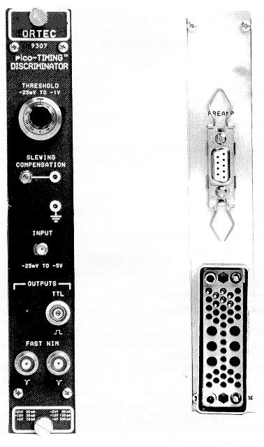
8 2 Fig Typical Block Diagram for Fluorescence Lifetime Spectrometer. 2. SPECIFICATIONS* 2.1. PERFORMANCE TIME SLEWING (Walk) <±20 ps shift in the timing output for input signal amplitudes from -150 mv to -1.5 V. (Typically <±50 ps for signal amplitudes from -50 mv to -5 V.) Measured using a 1-ns-wide input pulse with 350-ps rise and fall times. PULSE-PAIR RESOLUTION <10 ns at the fast negative NIM outputs. MAXIMUM INPUT/OUTPUT RATE Accepts burst rates up to 100 MHZ. OPERATING TEMPERATURE RANGE 0 TO 50 C. THRESHOLD TEMPERATURE SENSITIVITY <±0.1 mv/ C (0 to 50 C). TRANSMISSION DELAY TEMPERATURE SENSITIVITY <±10 ps/ C (0 to 50 C.) 2.2. CONTROLS AND INDICATORS THRESHOLD Front-panel, 10-turn potentiometer with locking dial allows adjustment of the input discriminator threshold from -25 mv to -1 V. SLEWING COMPENSATION Front-panel, 20-turn, screwdriver fine-tuning to minimize time slewing as a function of input pulse amplitude. Adjustable over a range of approximately ±30 mv. A front-panel test point located next to the potentiometer facilitates monitoring the actual setting. Test point output impedance: 100 S. OUTPUT LED Front-panel LED flashes on each output pulse to indicate active triggering INPUTS INPUT Front-panel SMA connector accepts unipolar input signals with amplitudes in the range of -50 mv to -5 V. Minimum input pulse width: 400 ps (FWHM). Maximum input pulse width: 5 ns (FWHM). Input impedance: 50 S. The input is protected to ±5 V OUTPUTS FAST NEGATIVE NIM OUTPUTS Front-panel BNC connectors provide two independent, fast negative NIM output logic pulses. Output amplitude is nominally -800 mv into a 50-S load. Pulse width is nominally 2.5 ns. TTL OUTPUT Front-panel BNC connector provides a positive TTL pulse, triggered by the fast negative NIM output. The 500-ns width of the TTL pulse is non-updating. Output impedance: <1 S, shortcircuit protected. PRAMP POWER Rear-panel, 9-pin D connector provides ±12-V and ±24-V power for the ORTEC Model GHz Preamplifier, the Model VT 120
9 3 fast-timing Preamplifier, or other preamplifiers utilizing the industry-standard preamplifier power plug ELECTRICAL AND MECHANICAL POWER REQUIRED The Model 9307 derives its power from a NIM bin/power supply, such as the ORTEC Model 4001A/4002D. Required dc voltages and currents are: +12 V and 35 ma, +6 V at 70 ma, -6 V at 360 ma, and -12 V at 100 ma. WEIGHT Net 0.9 kg (2.0 lb). Shipping 1.8 kg (4.0 lb). DIMENSIONS NIM-standard single-width module, 3.43 X cm (1.35 X in.) Front panel per DOE/ER-0457T ORDERING INFORMATION To order, specify: Model Description 9307 pico-timing Discriminator SMA SMA SMA SMA/BNC BNC/SMA RG-58U (50-S) Coaxial Cable with SMA Connectors, 0.15-m length RG-58U (50-S) Coaxial Cable with SMA Connectors, 0.5-m length RG-58U (50-S) Coaxial Cable with SMA Connectors, 1.5-m length SMA to BNC Adapter with male SMA and female BNC BNC to SMA Adapter with male BNC and female SMA 3. INSTALLATION AND OPERATION 3.1. GENERAL The Model 9307 power requirements must be furnished from a NIM-standard bin/power supply that includes ±6-V power distribution, such as the ORTEC 4001A/4002D, 4001C/4002D, or 4001C/4002E NIM Bins/Power Supplies. The NIM bin/power supply in which the 9307 normally will be operated is designed for relay rack mounting. If the equipment is rack mounted, be sure that there is adequate ventilation to prevent excessive localized heating in the Model The temperature equipment mounted in racks can easily exceed the maximum limit of 50 C unless precautions are taken CONNECTION TO POWER The power demanded by a NIM bin full of NIM modules that incorporate high-density electronic circuits can exceed the maximum power available from the NIM bin power supply. Before installing the modules in the NIM bin, add the current requirements specified for each module, and check that the total current required at each voltage does not exceed the maximum output of the power supply. Also check the total power required against the maximum power specification for the power supply. If the suite of modules demands excessive power, some of the modules must be moved to a second NIM bin/power supply. CAUTION Do not insert the Model 9307 in a NIM bin without first turning off the NIM bin power. Inserting the module in the NIM bin with power on may damage the ultra-fast comparators in the Model The NIM bin power should be turned on only after the Model 9307 has been securely installed in the NIM bin. Before installing the Model 9307 in the NIM bin, turn off the NIM bin power, then slide the 9307 into a convenient slot and tighten the retaining screws at the top and bottom of the module. The Model 9307 should be installed in the NIM bin at a location that is close to the module that utilizes the output of the Model After all the modules have been mounted in the NIM bin, turn on the NIM bin power. Using a voltmeter and the test points at the right side of the NIM bin, check that the power supply voltages are operating at their correct values. A sagging power voltage indicates that the current
10 4 demand from the modules exceeds the limit of the power supply, or it indicates a possible fault in the power supply INPUT CONNECTIONS For Detector Rise Times <1 ns The Model 9307 pico-timing Discriminator has been designed for use with ultra-fast detectors, which have pulse rise times as short as 350 ps. In order to obtain the best time resolution, special care must be exercised to preserve the fast rise time. Normally, this requires the use of short, 50-S, coaxial cables with SMA connectors. Typically, a fast preamplifier, such as the Model GHz Preamplifier, is required between the detector and the input of the Model 9307 to increase the amplitude of the detector output pulses (see Fig. 1.2). The total length of the coaxial cables from the detector to the preamplifier and from the preamplifier to the pico-timing Discriminator should be kept less than 1.7 meters to avoid degradation of the signal rise time. The coaxial cable between the detector and the Model 9306 preamplifier also should be as short as possible to minimize electrical interference from neighboring instruments. The inputs of both the Model 9306 and the Model 9307 include internal 51- S resistors for proper termination of the 50-S cable. For Detector rise Times >1 ns If a detector having an output rise time $1 ns is employed, a longer length of 50-S coaxial cable with BNC connectors can be used between the preamplifier and the Model See the Ordering Information at the end of Section 2, or consult the ORTEC catalog for the proper coaxial cables and the BNC to SMA connector adapters. If the detector produces negative pulses with amplitudes that cover a substantial portion of the range from -50 mv to -5 V, the detector can be connected directly to the input of the Model Note that the input of the Model 9307 is protected only to ±5 V. If the detector produces signal amplitudes beyond ±5 V, diodes will have to be installed at the signal source to limit the amplitude to within ±5 V. If signal amplification is required for a detector having a rise time $1 ns, the Model VT120 Fast-Timing Preamplifier should be used in place of the Model Preamplifier Power Connection Either the Model 9306 or the Model VT120 can derive its power from the preamplifier power plug on the Model 9307 rear panel. Avoiding Ground-Loop Noise To avoid noise induced by ground loops, the detector and preamplifier should be isolated from any grounds in the vicinity of the detector. The only ground supplied to the detector and preamplifier should come directly from the NIM bin housing the Model This can be accomplished by mounting the detector high-voltage supply in the NIM bin next to the Model 9307, and by relying on the high-voltage cable, the preamplifier power cable, and the coaxial signal cables to provide the ground to the preamplifier and detector. Getting the Right Input Signal Polarity The Model 9307 input requires a negative signal polarity. This is the normal pulse polarity provided by the anode of a photomultiplier tube (PMT), a microchannel plate, or a microchannel plate PMT. For detectors which have a positive signal polarity, a fast inverting transformer (such as the Model IT 100) or the Model VT 120B Fast-Timing Preamplifier can be used to invert the signal. The Proper Input Pulse Width For best timing performance, the pulse supplied to the input of the Model 9307 should have a width at half its amplitude that falls in the range of 400 ps to 5 ns. This is the typical pulse width for single-photon or single-ion timing with micorchannel plates, microchannel plate PMTs, and photmultiplier tubes. The pico-timing Discriminator can be used with fast scintillators on PMTs, but the resulting time resolution will be 10% to 30% worse than can be obtained with a conventional Constant-Fraction Discriminator. Conversely, the Model 9307 is the optimum solution for single-photon or single-ion timing OUTPUT CONNECTIONS There are three outputs on the Model 9307: two fast negative NIM logic outputs, and one TTL output. FAST NIM Outputs The two FAST NIM outputs are intended for precise timing applications with a Time-to-Amplitude Converter (TAC), such as the ORTEC Models 457, 566, or 567 (see Fig. 1.2). Each of these two outputs generates a current pulse, which has a rise time of ~400 ps, a width of 2.5 ns, and an amplitude of approximately -16 ma. The leading edge of the output pulse at the input to the pico-timing Discriminator. The FAST NIM outputs are intended to drive a 50-S cable terminated in 50 S at the remote end of the cable.
11 5 Thus, these two outputs produce pulses of nominally -800-mV amplitude on a terminated 50-S cable. The quiescent level between pulses is nominally 0 V. Most TACs provide the 50-S termination internally at their inputs. A 50-S cable with BNC connectors can be used to connect the FAST NIM outputs to either the START or STOP input on the TAC. Normally, the length of this cable is not critical. When driven by a noise-free pulser with a rise time <1 ns at the input of the Model 9307, the pico-timing discriminator is capable of a time resolution <15 ps FWHM (Full Width at Half Maximum peak height). Consequently, most of the contribution to the time resolution comes from timing jitter or noise in the detector connected to the Model 9307 input. TTL Output The third output provides a positive TTL logic pulse with a width of approximately 500 ns. This output is useful for driving slower instruments such as counters and ratemeters. Either 50-S or 93-S cables with BNC connectors can be used with the TTL output. For cable lengths <1 meter, it is not necessary to terminate this cable in its characteristic impedance. The TTL output can drive either TTL inputs or Slow Positive NIM Logic inputs. The TTL output is triggered from the FAST NIM outputs, and it flashes the adjacent LED on every output pulse ADJUSTING THE INPUT SIGNAL AMPLITUDE Large Pulse Amplitudes from a PMT Anode If the amplitude of the output signal from the anode of a photmultiplier tube is large enough to use directly with the input to the pico-timing Discriminator, the range of signal amplitudes can be selected by adjusting the high voltage applied to the photomultiplier tube. An oscilloscope with a 500- MHZ bandwidth and a 50-S input impedance is adequate to measure the PMT pulses. The high voltage should be increased until the signals cover most of the 0 to -5-V operating range. The PMT manufacturer s instructions regarding operating voltage and maximum anode signal should be consulted to select the optimum voltage range, and to avoid distortion of the signals by anode saturation. Do not exceed the ±5-V limits on the input to the Model Amplified Pulses with >1-ns Rise Times For single-photon counting with a photomultiplier tube, a fast amplifier is typically needed to increase the amplitude of the pulses from the PMT anode. An oscilloscope with a 500-MHZ bandwidth and a 50-S input impedance can be used to observe the amplified pulses. The easiest way to select the pulse amplitude range is to adjust the high voltage on the PMT. Consult the PMT manufacturer s specifications for the allowable voltage on the photmultiplier tube. The high voltage should be adjusted until the largest pulse amplitudes lie just within the linear range of the amplifier output. If the linear range of the amplifier output is exceeded, the pulses will be distorted, and the time resolution will be compromised. Do not exceed the ±5-V limit of the Model 9307 input. Amplified Pulses with <1-ns Rise Times For microchannel plate PMTs, a fast preamplifier with an output rise time of about 350 ps is typically used to prepare the pulses for the Model 9307 input. To observe these pulses an oscilloscope with a bandwidth $4 GHz and a 50-S input impedance is required. The simplest method for selecting the range of signal amplitudes is to adjust the high voltage applied to the microchannel plate PMT. Consult the manufacturer s specifications regarding the allowable range of anode voltage. If it is not possible to adjust the anode voltage, high bandwidth attenuators, such as the Hewlett Packard Models HP 8494B and HP 8495B, can be inserted between the microchannelplate PMT output and the input to the fast preamplifier. These attenuators can be adjusted to select the desired range of pulse amplitudes at the preamplifier output. One of the above two methods should be used to adjust the gain so that the largest pulse amplitudes are just less than the linear limit of the preamplifier output. Do not exceed the ±5-V limit of the Model 9307 input. If a 4-GHz oscilloscope is not available, the pulse amplitude can be increased until a noticeable distortion of the peak in the time spectrum is observed (see section 3.7). This distortion is caused by saturation of the pulses at the preamplifier output. Gradually reduce the pulse amplitudes until the distortion is eliminated.
12 THRESHOLD ADJUSTMENT Function and Range The 10-turn locking dial on the front panel controls the amplitude threshold for accepting input pulses that are allowed to produce a timing output. This threshold is adjustable over the nominal range of -25 mv to -1.0 V. The dial reading is moderately accurate on pulse widths near the 5 ns FWHM limit. On pulse widths approaching the 400 ps limit the actual threshold will be higher than the dial indication due to bandpass limitations in comparator circuits. Initial Adjustment to Reject Noise The THRESHOLD control is typically used to prevent the Model 9307 from triggering on low-level noise from the signal source. The simplest way to adjust this control is to turn off the supply of photons or ions to the detector, while leaving the detector in its normal operating condition. Subsequently, the THRESHOLD dial is turned counter-clockwise until the output LED glows brightly. Under this condition the Model 9307 is triggering on noise from the detector and preamplifier. Next, the THRESHOLD dial is slowly rotated clockwise, until the LED turns off. Locking the dial at this point will set the threshold just above the detector noise. Raising the Threshold for Improved Time Resolution When the source of photons or ions is turned on, it may be desirable to raise the Threshold above the value set in the previous paragraph. The smallest pulse amplitudes from the detector have inherently greater timing jitter. Consequently, the time resolution with any detector can be improved by rejecting the lower amplitude pulses. The best way to make this additional adjustment of the THRESHOLD is to monitor the counting rate at the Model 9307 TTL output on a counting ratemeter or counter/timer. Connect the TTL output of the Model 9307 to the input of the ratemeter or counter/timer. Note the counting rate produced by the setting in the previous paragraph. Now raise the THRESHOLD to a higher value. Record the THRESHOLD dial reading, the counting rate, and the time resolution in the time spectrum on the multichannel analyzer (Fig. 1.2). Repeat this process for a number of threshold setting and plot the results on graph paper. From the graph, choose a THRESHOLD setting that provides the best compromise between better time resolution and higher counting rate. Lock the THRESHOLD dial at the desired setting ADJUSTING THE SLEWING COMPENSATION Function and Effect When the SLEWING COMPENSATION is properly adjusted to match the characteristics of the signal from the detector and preamplifier, there will be minimal systematic bias in marking the arrival time of smaller pulses versus larger pulses. If the SLEWING COMPENSATION is adjusted too far in the negative voltage direction, the lower-amplitiude pulses will produce a timing output that arrives too early compared to the arrival of the timing output from the higher-amplitude pulses. If the SLEWING COMPENSATION is adjusted too far in the positive voltage direction, the smaller pulses will generate a timing output that arrives too late compared to the arrival time of the timing output from the larger pulses. Setting up for the Adjustment The easiest way to optimize the SLEWING COMPENSATION is to set up the complete timing system (e.g., Fig. 1.2). Choose a pulsed source of photons or ions that should generate a timing peak having a FWHM of <100 ps. In other words, the pulsed source of ions or photons must have negligible intrinsic time spread. Determining the Initial Conditions Record the THRESHOLD setting that will be used for normal operation. Next, set the THRESHOLD control on the Model 9307 as low as possible without triggering on noise (see section 3.6). Measure the SLEWING COMPENSATION setting at the frontpanel test points with a voltmeter. The reading should be measured and recorded to the nearest mv. Disconnect the voltmeter and record a time spectrum on the MCA with at least 10,000 counts in the peak height. Observe the shape of the peak on a logarithmic vertical scale. Note the width of the peak and the symmetry of the peak shape, particularly near the base of the peak. If the base of the time peak is skewed towards earlier time, the SLEWING COMPENSATION should be adjusted towards a more positive voltage. If the base of the peak is skewed towards later time, the SLEWING COMPENSATION should be adjusted towards a more negative voltage. Making the Necessary Adjustments Make the adjustment of the SLEWING COMPENSATION indicated by the results in the previous paragraph. Use the voltmeter to monitor the change. Remove the voltmeter and record another time spectrum.
13 7 Observe the effect of the adjustment on the symmetry of the time peak at its base. Make further adjustments in the same manner until satisfactory symmetry and minimum peak width and achieved. Typically, a setting of -12 ±10 mv will be measured when optimum SLEWING COMPENSATION has been achieved. Asymmetry Intrinsic to the Signal Source Note that the detector or the photon source may have an inherent asymmetry that shows up in the time spectrum. In such cases it will not be possible to achieve perfect peak symmetry with the SLEWING COMPENSATION (see Fig. 1.1, for example). When adjusting the SLEWING COMPENSATION on the Model 9307 it will become obvious which asymmetries in the time peak are affected by the SLEWING COMPENSATION adjustment, and which asymmetries are intrinsic to the detector and pulsed photon source. Returning to the Operating Conditions Once the desired SLEWING COMPENSATION adjustment has been achieved, record the final voltmeter reading for future reference, and return the THRESHOLD adjustment to the desired operating setting determined in Section 3.6. The Model 9307 is now ready for use LIMITING THE COUNTING RATE TO AVOID SPECTRUM DISTORTION Typically, the Model 9307 pico-timing Discriminator will be used in conjunction with a TIME-to-Amplitude Converter (TAC), as illustrated in Fig Time-to-Amplitude Converters enable the measurement of nanosecond time intervals with picosecond time resolution. To achieve such high resolution one must accept a compromise, because a Time-to-Amplitude Converter can only measure the time interval between pairs of start and stop pulses. In other words, the TAC measures the time interval from the first accepted start pulse to the next stop pulse. It ignores all subsequent start pulses and any additional stop pulses until it has finished converting the first pair of start and stop pulses. Consider the obviously logical arrangement, where the laser pulse in Fig. 1.2 is the start pulse for the TAC and the detected fluoresced photon generates the stop pulse. (The benefit of reversed start/stop logic will be discussed in the next section.) If the probability of observing a fluoresced photon after each laser pulse is very high, then fluoresced photons emitted late in the decay time scale will often find that the TAC has already responded to a stop pulse from a photon emitted earlier in the decay process. Consequently, the efficiency for recording the shortest decay time intervals will be approximately 100%, while the efficiency for the longer time intervals will be much less than 100%. This causes a distortion of the recorded time spectrum and leads to an error in the measurement of the fluorescence decay time constant. The distortion of the time spectrum can be made negligible by limiting the counting rate of the detected fluoresced photons. For example, the optical intensity can be restricted so that the probability of detecting a single fluoresced photon after each laser pulse is <0.01 (or <1%). Under these circumstances the probability of observing 2 photons at the detector output for each laser pulse will be <(0.01) 2, which is <1% of the single photon rate. This will render the distortion of the time spectrum insignificant. To turn this guideline into a limit on the detected counting rate of photons, it is sufficient to know the repetition rate of the pulsed laser at the sample. For example, a pulsed laser repetition rate of 1 MHZ requires an upper limit on the fluoresced photon counting rate of 10 KHz (i.e., 0.01 x 1 MHZ) to achieve less than 1% distortion of the time spectrum from the lost second-stop pulses. In general, the limit on the detected photon rate to avoid significant spectrum distortion from lost second-stop pulses with a pulsed excitation source is: Max. Counting Rate #0.01 x Source Repetition Rate. Operating at counting rates below this limit will further reduce the distortion. Note that this limit applies to the start pulse rate when the reversed start/stop logic is used, as described in the next section THE BENEFIT OF REVERSED START/STOP LOGIC When operating with a pulsed excitation source that has a high repetition rate, the efficiency of data collection can be improved drastically by using reversed start and stop logic. Instead of starting the TAC with the signal from the pulsed source, and stopping the TAC with the detected fluoresced photon, the TAC is started with the fluoresced photon and stopped by a delayed source pulse. This
14 8 is the scheme actually depicted in Fig The signal from the pulsed excitation source is delayed by approximately 90% of the TAC time range and used as the stop pulse. The fluoresced photon detector provides the start pulse. This results in a time spectrum that is reversed, with shorter times to the right and longer times to the left. If reversed start/stop logic is NOT used, the TAC spends most of its time converting start pulses without stop pulses. This results in excessive dead time in the TAC and MCA. The TAC and MCA spend most of the time processing signals with no recordable data. The reversed start/stop logic solves this problem. The TAC only starts a conversion on the low rate pulses from the fluoresced photon detector. For each of these start pulses a delayed stop pulse from the pulsed excitation source is guaranteed to occur. With reversed start/stop logic the busy time or dead time of the TAC and ADC is determined by the collection of useful data at a counting rate set by the fluoresced photon detector. In general, it is best to use the signal with the higher counting rate as the stop input to the TAC. 4. MAINTENANCE AND SERVICE No regular maintenance is required for the Model 9307, except to remove any collection of dust that might interfere with good electrical insulation and adequate heat dissipation. In the unlikely event of instrument failure, this unit can be returned to the ORTEC factory for service and repair at a nominal cost. The ORTEC standard procedure for repair ensures the same quality control and checkout that are used for a new instrument. Always contact Customer Service at ORTEC before sending an instrument for repair to obtain shipping required Return Authorization Number can be assigned to the unit. The Return Authorization Number should be written on the address label, the outside of the package, and on the explanatory letter enclosed with the unit. A multitude of packages flow into the Receiving Department at ORTEC each day. Consequently, the Return Authorization Number is critical to ensure that your package will be promptly routed to the Customer Service Department. After inspecting your unit, the Customer Service Department will contact you regarding the necessary repairs and the expected cost.
15 9 Table 1. Bin/Module Connector Pin Assignments for Standard Nuclear Instrument Modules per DOE/ER-0457T Pin Function Pin Function 1 +3 V 23 Reserved 2!3 V 24 Reserved 3 Spare Bus 25 Reserved 4 Reserved Bus 26 Spare 5 Coaxial 27 Spare 6 Coaxial * V 7 Coaxial *29!24 V V dc 30 Spare Bus 9 Spare 31 Spare *10 +6 V 32 Spare *11!6 V * V ac (Hot) 12 Reserved Bus *34 Power Return Ground 13 Spare 35 Reset (Scaler) 14 Spare 36 Gate 15 Reserved 37 Reset (Auxiliary) * V 38 Coaxial *17!12 V 39 Coaxial 18 Spare Bus 40 Coaxial 19 Reserved Bus * V ac (Neutral) 20 Spare *42 High-Quality Ground 21 Spare G Ground Guide Pin 22 Reserved Pins marked (*) are installed and wired in ORTEC s Model 4001A and 4001C Modular System Bins.
Model 9302 Amplifier-Discriminator Operating and Service Manual
 Model 9302 Amplifier-Discriminator Operating and Service Manual Printed in U.S.A. ORTEC Part No. 733690 1202 Manual Revision C Advanced Measurement Technology, Inc. a/k/a/ ORTEC, a subsidiary of AMETEK,
Model 863 Quad Timing Filter Amplifier Operating and Service Manual
 Model 863 Quad Timing Filter Amplifier Operating and Service Manual Printed in U.S.A. ORTEC Part No. 733960 0411 Manual Revision C Advanced Measurement Technology, Inc. a/k/a/ ORTEC, a subsidiary of AMETEK,
Model 9305 Fast Preamplifier Operating and Service Manual
 Model 9305 Fast Preamplifier Operating and Service Manual This manual applies to instruments marked Rev 03" on rear panel. Printed in U.S.A. ORTEC Part No.605540 1202 Manual Revision B Advanced Measurement
Model 113 Scintillation Preamplifier Operating and Service Manual
 Model 113 Scintillation Preamplifier Operating and Service Manual Printed in U.S.A. ORTEC Part No. 717560 1202 Manual Revision B Advanced Measurement Technology, Inc. a/k/a/ ORTEC, a subsidiary of AMETEK,
Model 533 Dual Sum and Invert Amplifier Operating and Service Manual
 Model 533 Dual Sum and Invert Amplifier Operating and Service Manual Printed in U.S.A. ORTEC Part No. 733410 1202 Manual Revision B Advanced Measurement Technology, Inc. a/k/a/ ORTEC, a subsidiary of AMETEK,
Model 416A Gate and Delay Generator Operating and Service Manual
 Model 416A Gate and Delay Generator Operating and Service Manual Printed in U.S.A. ORTEC Part No. 733160 1202 Manual Revision E Advanced Measurement Technology, Inc. a/k/a/ ORTEC, a subsidiary of AMETEK,
Model 427A Delay Amplifier Operating and Service Manual
 Model 427A Delay Amplifier Operating and Service Manual This manual Applies to instruments marked Rev 22" on rear panel Printed in U.S.A. ORTEC Part No. 733210 1202 Manual Revision B Advanced Measurement
ScintiPack Model 296 Photomultiplier Base with Preamplifier and High Voltage Power Supply Operating and Service Manual
 ScintiPack Model 296 Photomultiplier Base with Preamplifier and High Voltage Power Supply Operating and Service Manual WARNING This equipment generates, uses, and can radiate radio frequency energy, and
Model 428 Detector Bias Supply Operating and Service Manual
 Model 428 Detector Bias Supply Operating and Service Manual Printed in U.S.A. ORTEC Part No. 733220 1202 Manual Revision C Advanced Measurement Technology, Inc. a/k/a/ ORTEC, a subsidiary of AMETEK, Inc.
Model 935 Quad Constant-Fraction 200-MHz Discriminator Operating and Service Manual
 Model 935 Quad Constant-Fraction 200-MHz Discriminator Operating and Service Manual U.S. Patent No. 4,179,644 Printed in U.S.A. ORTEC Part No. 753770 0503 Manual Revision H ii $GYDQFHG0HDVXUHPHQW7HFKQRORJ\,QF
Model 426 Linear Gate Operating and Service Manual
 Model 426 Linear Gate Operating and Service Manual This manual applies to instruments marked Rev 23" on rear panel Printed in U.S.A. ORTEC Part No. 733200 1202 Manual Revision B Advanced Measurement Technology,
Model 449 Log/Lin Ratemeter Operating and Service Manual
 Model 449 Log/Lin Ratemeter Operating and Service Manual Printed in U.S.A. ORTEC Part No. 733270 1202 Manual Revision D Advanced Measurement Technology, Inc. a/k/a/ ORTEC, a subsidiary of AMETEK, Inc.
Model 480 Pulser Operating and Service Manual
 Model 480 Pulser Operating and Service Manual Printed in U.S.A. ORTEC Part No. 733390 1202 Manual Revision B Advanced Measurement Technology, Inc. a/k/a/ ORTEC, a subsidiary of AMETEK, Inc. WARRANTY ORTEC*
Model 439 Digital Current Integrator Operating Manual
 Model 439 Digital Current Integrator Operating Manual Printed in U.S.A. ORTEC Part No. 733240 0908 Manual Revision K Advanced Measurement Technology, Inc. a/k/a/ ORTEC, a subsidiary of AMETEK, Inc. WARRANTY
Model 542 Linear Gate and Stretcher Operating and Service Manual
 Model 542 Linear Gate and Stretcher Operating and Service Manual NOTE: A substitution for the dual diode package (MSD6100) may have been made in this unit. If so, two 1N4153 diodes were used to replace
Model 276L Low-Power Photomultiplier Base Operating and Service Manual
 Model 276L Low-Power Photomultiplier Base Operating and Service Manual Printed in U.S.A. ORTEC Part No. 762870 0702 Manual Revision C $GYDQFHG 0HDVXUHPHQW 7HFKQRORJ\,QF a/k/a/ ORTEC, a subsidiary of AMETEK,
Model 566 Time-to-Amplitude Converter (TAC) Operating and Service Manual
 Operating and Service Manual") Model 566 Time-to-Amplitude Converter (TAC) Operating and Service Manual Printed in U.S.A. ORTEC Part No. 678950 0411 Manual Revision F Advanced Measurement Technology, Inc. a/k/a/ ORTEC, a subsidiary
Model 566 Time-to-Amplitude Converter (TAC) Operating and Service Manual Printed in U.S.A. ORTEC Part No. 678950 0411 Manual Revision F Advanced Measurement Technology, Inc. a/k/a/ ORTEC, a subsidiary
Model 142AH Preamplifier Operating and Service Manual
 Model 142AH Preamplifier Operating and Service Manual Printed in U.S.A. ORTEC Part No. 733990 0202 Manual Revision B $GYDQFHG 0HDVXUHPHQW 7HFKQRORJ\,QF a/k/a/ ORTEC, a subsidiary of AMETEK, Inc. WARRANTY
2001A. 200KHz Function Generator Instruction Manual. 99 Washington Street Melrose, MA Phone Toll Free
 2001A 200KHz Function Generator Instruction Manual 99 Washington Street Melrose, MA 02176 Phone 781-665-1400 Toll Free 1-800-517-8431 Visit us at www.testequipmentdepot.com WARRANTY Global Specialties
Model 673 Spectroscopy Amplifier and Gated Integrator Operating and Service Manual
 Model 673 Spectroscopy Amplifier and Gated Integrator Operating and Service Manual Printed in U.S.A. ORTEC Part No. 675590 0202 Manual Revision B $GYDQFHG 0HDVXUHPHQW 7HFKQRORJ\,QF a/k/a/ ORTEC, a subsidiary
Model 7000 Low Noise Differential Preamplifier
 Model 7000 Low Noise Differential Preamplifier Operating Manual Service and Warranty Krohn-Hite Instruments are designed and manufactured in accordance with sound engineering practices and should give
PLL Synchronizer User s Manual / Version 1.0.6
 PLL Synchronizer User s Manual / Version 1.0.6 AccTec B.V. Den Dolech 2 5612 AZ Eindhoven The Netherlands phone +31 (0) 40-2474321 / 4048 e-mail AccTecBV@tue.nl Contents 1 Introduction... 3 2 Technical
Model 460 Delay Line Amplifier Operating and Service Manual
 Model 460 Delay Line Amplifier Operating and Service Manual Printed in U.S.A. ORTEC Part No. 733320 1202 Manual Revision C Advanced Measurement Technology, Inc. a/k/a/ ORTEC, a subsidiary of AMETEK, Inc.
LUDLUM MODEL MODEL AND MODEL GAMMA SCINTILLATORS. June 2017
 LUDLUM MODEL 44-20 MODEL 44-20-1 AND MODEL 44-20-3 GAMMA SCINTILLATORS June 2017 LUDLUM MODEL 44-20 MODEL 44-20-1 AND MODEL 44-20-3 GAMMA SCINTILLATORS June 2017 STATEMENT OF WARRANTY Ludlum Measurements,
SI-125 Power Amplifier Manual 6205 Kestrel Road; Mississauga, Ontario; Canada; L5T 2A1 November 2016, Rev 0.5
 SI-125 Power Amplifier Manual 6205 Kestrel Road; Mississauga, Ontario; Canada; L5T 2A1 November 2016, Rev 0.5 Phone: (905) 564-0801 Fax: (905) 564-0806 www.telecor.com E:\T2-108\T2-M108-ABC\T2-M108-B.doc/AD
Model 855 Dual Spectroscopy Amplifier Operating and Service Manual
 Model 855 Dual Spectroscopy Amplifier Operating and Service Manual This manual applies to instruments marked Rev. 03" on rear panel. Printed in U.S.A. ORTEC Part No. 717490 0406 Manual Revision C $GYDQFHG0HDVXUHPHQW7HFKQRORJ\,QF
Current Probes. User Manual
 Current Probes User Manual ETS-Lindgren Inc. reserves the right to make changes to any product described herein in order to improve function, design, or for any other reason. Nothing contained herein shall
AMP-13 OPERATOR S MANUAL
 AMP-13 OPERATOR S MANUAL Version 2.0 Copyright 2008 by Vatell Corporation Vatell Corporation P.O. Box 66 Christiansburg, VA 24068 Phone: (540) 961-3576 Fax: (540) 953-3010 WARNING: Read instructions carefully
HP 86290B RF PLUG-IN GHz HEWLETT PACKARD
 OPERATING AND SERVICE MANUAL. HP 86290B RF PLUG-IN 2.0-18.6 GHz HEWLETT PACKARD COPYRIGHT AND DISCLAIMER NOTICE Copyright - Agilent Technologies, Inc. Reproduced with the permission of Agilent Technologies
Model Hz to 10MHz Precision Phasemeter. Operating Manual
 Model 6610 1Hz to 10MHz Precision Phasemeter Operating Manual Service and Warranty Krohn-Hite Instruments are designed and manufactured in accordance with sound engineering practices and should give long
RIGOL. User s Guide. RP5600 Passive Probe. July 2010 RIGOL Technologies, Inc.
 User s Guide RP5600 Passive Probe July 2010 RIGOL Technologies, Inc. Guaranty and Declaration Copyright 2010 RIGOL Technologies, Inc. All Rights Reserved. Trademark Information RIGOL is a registered trademark
AMP-12 OPERATOR S MANUAL
 AMP-12 OPERATOR S MANUAL Version 1.0 Copyright 2002 by Vatell Corporation Vatell Corporation P.O. Box 66 Christiansburg, VA 24068 Phone: (540) 961-3576 Fax: (540) 953-3010 WARNING: Read instructions carefully
INSTRUCTION MANUAL. March 11, 2003, Revision 3
 INSTRUCTION MANUAL Model 701A Stimulator March 11, 2003, Revision 3 Copyright 2003 Aurora Scientific Inc. Aurora Scientific Inc. 360 Industrial Parkway S., Unit 4 Aurora, Ontario, Canada L4G 3V7 Tel: 1-905-727-5161
SUBNANOSECOND PULSE GENERATOR PPG-2/1000 USER MANUAL
 SUBNANOSECOND PULSE GENERATOR PPG-2/1000 USER MANUAL 2015 Megaimpulse Ltd. Copyright 2015 MEGAIMPULSE Ltd. All Rights Reserved. MEGAIMPULSE LTD. PROVIDES THIS MANUAL "AS IS" WITHOUT WARRANTY OF ANY KIND,
Photon Counters SR430 5 ns multichannel scaler/averager
 Photon Counters SR430 5 ns multichannel scaler/averager SR430 Multichannel Scaler/Averager 5 ns to 10 ms bin width Count rates up to 100 MHz 1k to 32k bins per record Built-in discriminator No interchannel
15-GHz & 25-GHz Photodetectors Models 1480-S & 1481-S
 1480-S FC Det revb.fm Page 1 Monday, January 14, 2013 11:38 AM USER S GUIDE 15-GHz & 25-GHz Photodetectors Models 1480-S & 1481-S Includes Model 1481-50-S These photodetectors are sensitive to electrostatic
Directed Energy, Inc Oakridge Dr., Suite 100, Fort Collins, CO
 PCO-7121 Laser Diode Driver Module Operation Manual Directed Energy, Inc. 1609 Oakridge Dr., Suite 100, Fort Collins, CO 80525 sales@ixyscolorado.com www.ixyscolorado.com Contents Contents... 3 Safety...
PCO-7114 Laser Diode Driver Module Operation Manual
 PCO-7114 Laser Diode Driver Module Operation Manual Directed Energy, Inc. 1609 Oakridge Dr., Suite 100, Fort Collins, CO 80525, (970) 493-1901 sales@ixyscolorado.com www.ixyscolorado.com Manual Document
INSTRUCTIONS MODEL AVC MONOCYCLE GENERATOR MODULE SERIAL NUMBER:
 A V T E C H E L E C T R O S Y S T E M S L T D. N A N O S E C O N D W A V E F O R M E L E C T R O N I C S S I N C E 1 9 7 5 P.O. BOX 265 OGDENSBURG, NY U.S.A. 13669-0265 TEL: 888-670-8729 (USA & Canada)
Glass Electrode Meter
 Glass Electrode Meter INSTRUCTION MANUAL FOR Glass Electrode R/C Meter MODEL 2700 Serial # Date PO Box 850 Carlsborg, WA 98324 U.S.A. 360-683-8300 800-426-1306 FAX: 360-683-3525 http://www.a-msystems.com
User s Guide. RP7000 Series Active Probe. Dec RIGOL Technologies, Inc.
 User s Guide RP7000 Series Active Probe Dec. 2012 RIGOL Technologies, Inc. Guaranty and Declaration Copyright 2011 RIGOL Technologies, Inc. All Rights Reserved. Trademark Information RIGOL is a registered
P5100A & P5150 High Voltage Probes Performance Verification and Adjustments
 x P5100A & P5150 High Voltage Probes Performance Verification and Adjustments ZZZ Technical Reference *P077053001* 077-0530-01 xx P5100A & P5150 High Voltage Probes Performance Verification and Adjustments
411LA Broadband Power Amplifier
 411LA Broadband Power Amplifier HIGH RF VOLTAGES MAY BE PRESENT AT THE OUTPUT OF THIS UNIT. All operating personnel should use extreme caution in handling these voltages and be thoroughly familiar with
ORTEC Experiment 13. Gamma-Gamma Coincidence with Angular Correlation. Equipment Required
 ORTEC Experiment 13 Equipment Required Two 905-3 2-in. x 2-in. NaI(Tl) Scintillation Detector Assemblies. Two 266 Photomultiplier Tube Bases. Two 113 Scintillation Preamplifiers. Two 556 High Voltage Power
LUDLUM MODEL 421 AND PMT BASE WITH PREAMPLIFIER/BIAS SUPPLY. October 2014 Serial Number and Succeeding Serial Numbers
 LUDLUM MODEL 421 AND 421-3 PMT BASE WITH PREAMPLIFIER/BIAS SUPPLY October 2014 Serial Number 200000 and Succeeding Serial Numbers LUDLUM MODEL 421 AND 421-3 PMT BASE WITH PREAMPLIFIER/BIAS SUPPLY October
Picosecond Time Analyzer Applications in...
 ORTEC AN52 Picosecond Time Analyzer Applications in... LIDAR and DIAL Time-of-Flight Mass Spectrometry Fluorescence/Phosphorescence Lifetime Spectrometry Pulse or Signal Jitter Analysis CONTENTS of this
BC145 SIGNAL ISOLATOR BOARD
 BC145 SIGNAL ISOLATOR BOARD 4/17 Installation & Operating Manual MN1373 Any trademarks used in this manual are the property of their respective owners. Important: Be sure to check www.baldor.com to download
TA MHz oscilloscope probe TA MHz oscilloscope probe
 TA375 100 MHz oscilloscope probe TA386 200 MHz oscilloscope probe User's Guide X1 X10 TA386 X1/X10 Max. 600 Vp Introduction This passive high-impedance oscilloscope probe is suitable for most oscilloscopes
Instruction Manual CT-6 High Frequency AC Current Probe
 Instruction Manual CT-6 High Frequency AC Current Probe 071-0453-00 Revision A Copyright Tektronix, Inc. All rights reserved. Tektronix products are covered by U.S. and foreign patents, issued and pending.
Model 2126 Constant Fraction Discriminator
 9231701B Model 2126 Constant Fraction Discriminator User s Manual Copyright 2005, Canberra Industries, Inc. All rights reserved. The material in this document, including all information, pictures, graphics
Amplified High Speed Photodetectors
 Amplified High Speed Photodetectors User Guide 3340 Parkland Ct. Traverse City, MI 49686 USA Page 1 of 6 Thank you for purchasing your Amplified High Speed Photodetector from EOT. This user guide will
P7313SMA 13 GHz Differential Probe
 x P7313SMA 13 GHz Differential Probe ZZZ Technical Reference *P077196802* 077-1968-02 xx P7313SMA 13 GHz Differential Probe ZZZ Technical Reference www.tektronix.com 077-1968-02 Copyright Tektronix. All
Model 3102D 0-2 kv H.V. Power Supply
 Features Compact single width NIM package Regulated up to ±2000 V dc. 1 ma output Noise and ripple 3 mv peak to peak Overload and short circuit protected Overload, inhibit and polarity status indicators
Distribution Amplifiers 1
 Distribution Amplifiers 1-30dB PUT 49-750 MHz 43 db GA POWER DOUBLED P/N: 1002705 REVERSE GA M MAX DESCRIPTION The R.L. DRAKE models DA8642, DA8632,, and DA7533, are broadband distribution amplifiers designed
Broadband Step-Up Transformer. User Manual
 Broadband Step-Up Transformer User Manual 990-1930 09/2004 Introduction Introduction About this unit The APC Step-Up Transformer provides 220 V power from 60 VAC Broadband cable systems. Safety Electrical
2015 RIGOL TECHNOLOGIES, INC.
 Service Guide DG000 Series Dual-channel Function/Arbitrary Waveform Generator Oct. 205 TECHNOLOGIES, INC. Guaranty and Declaration Copyright 203 TECHNOLOGIES, INC. All Rights Reserved. Trademark Information
Experiment 10. The Speed of Light c Introduction Apparatus
 Experiment 10 The Speed of Light c 10.1 Introduction In this experiment you will measure the speed of light, c. This is one of the most fundamental constants in physics, and at the same time the fastest
TIA-527 Balanced Optical/Electrical Converter. Operating Instructions
 TIA-527 Balanced Optical/Electrical Converter Operating Instructions Terahertz Technologies Inc.169 Clear Road Oriskany NY 13424 (315) 736-3642 FAX (315) 736-4078 E-mail sales@terahertztechnologies.com
Broadband Power Amplifier
 601L Broadband Power Amplifier HIGH RF VOLTAGES MAY BE PRESENT AT THE OUTPUT OF THIS UNIT. All operating personnel should use extreme caution in handling these voltages and be thoroughly familiar with
DA560D COMPACT SERIES. INSTALLATION / OWNER'S MANUAL Mobile Power Amplifiers
 DA560D COMPACT SERIES INSTALLATION / OWNER'S MANUAL Mobile Power Amplifiers Preparation Please read entire manual before installation. Due to the technical nature of amplifiers, it is highly recommended
INTEGRATED HYBRID TUBE AMPLIFIER VT Model HYBRID TUBE AMPLIFIER
 INTEGRATED HYBRID TUBE AMPLIFIER Model VT-40.2 HYBRID TUBE AMPLIFIER OWNER S MANUAL Safety Instructions The lightning flash with the arrowhead symbol within an equilateral triangle is intended to alert
CT-2 and CT-3 Channel Taggers OPERATION MANUAL
 CT-2 and CT-3 Channel Taggers OPERATION MANUAL Trilithic Company Profile Trilithic is a privately held manufacturer founded in 1986 as an engineering and assembly company that built and designed customer-directed
DA6002D-DA10004D. INSTALLATION / OWNER'S MANUAL Mobile Power Amplifiers
 DA6002D-DA10004D INSTALLATION / OWNER'S MANUAL Mobile Power Amplifiers Preparation Please read entire manual before installation. Due to the technical nature of amplifiers, it is highly recommended that
XPR522 XPR540. XPR SERIES INSTALLATION / OWNER'S MANUAL Mobile Power Amplifiers
 XPR522 XPR540 XPR SERIES INSTALLATION / OWNER'S MANUAL Mobile Power Amplifiers Preparation Please read entire manual before installation. Due to the technical nature of amplifiers, it is highly recommended
Amplified Photodetectors
 Amplified Photodetectors User Guide (800)697-6782 sales@eotech.com www.eotech.com Page 1 of 6 EOT AMPLIFIED PHOTODETECTOR USER S GUIDE Thank you for purchasing your Amplified Photodetector from EOT. This
PML Channel Detector Head for Time-Correlated Single Photon Counting
 Becker & Hickl GmbH Nahmitzer Damm 30 12277 Berlin Tel +49 30 787 56 32 Fax +49 30 787 57 34 email: info@becker-hicklde http://wwwbecker-hicklde PML16DOC PML-16 16 Channel Detector Head for Time-Correlated
CANARY AUDIO. Power Amplifier CA-309 OWNER S MANUAL. Handcrafted in California MADE IN USA
 CANARY AUDIO 300B Push-Pull Parallel Power Amplifier Mono Block Handcrafted in California CA-309 OWNER S MANUAL MADE IN USA Dear Customer: Please allow us to take this opportunity to thank you for purchasing
SRVODRV REV7 INSTALLATION NOTES
 SRVODRV-8020 -REV7 INSTALLATION NOTES Thank you for purchasing the SRVODRV -8020 drive. The SRVODRV -8020 DC servo drive is warranted to be free of manufacturing defects for 1 year from the date of purchase.
Analog-to-Digital-Converter User Manual
 7070 Analog-to-Digital-Converter User Manual copyright FAST ComTec GmbH Grünwalder Weg 28a, D-82041 Oberhaching Germany Version 2.0, July 7, 2005 Software Warranty FAST ComTec warrants proper operation
INSTALLATION GUIDE. Video Balun Transceiver with fixed BNC for twisted pair operation with other balun transceivers or active receivers.
 INSTALLATION GUIDE VB37M Video Balun Transceiver for Twisted Pair Description Video Balun Transceiver with fixed BNC for twisted pair operation with other balun transceivers or active receivers. The VB37M
VT1586A Rack Mount Terminal Panel Installation and User s Manual
 VT1586A Rack Mount Terminal Panel Installation and User s Manual Manual Part Number: 82-0095-000 Rev. June 16, 2003 Printed in U.S.A. Certification VXI Technology, Inc. certifies that this product met
PDB4. Four Channel Passive Direct Box USER'S GUIDE
 PDB4 Four Channel Passive Direct Box USER'S GUIDE IMPORTANT SAFETY INSTRUCTIONS - READ FIRST This symbol, wherever it appears, alerts you to important operating and maintenance instructions in the accompanying
P5100A & P5150 High Voltage Probes Performance Verification and Adjustments
 x P5100A & P5150 High Voltage Probes Performance Verification and Adjustments ZZZ Technical Reference *P077053002* 077-0530-02 xx P5100A & P5150 High Voltage Probes Performance Verification and Adjustments
CURRENT MEARUREMENT SHUNT CS-10/500 USER MANUAL
 CURRENT MEARUREMENT SHUNT CS-10/500 USER MANUAL 2017 Megaimpulse Ltd. Copyright 2017 MEGAIMPULSE Ltd. All Rights Reserved. MEGAIMPULSE LTD. PROVIDES THIS MANUAL "AS IS" WITHOUT WARRANTY OF ANY KIND, EITHER
DA604D DA954D DA501D DA801D COMPACT SERIES. INSTALLATION / OWNER'S MANUAL Mobile Power Amplifiers
 DA604D DA954D DA501D DA801D COMPACT SERIES INSTALLATION / OWNER'S MANUAL Mobile Power Amplifiers Preparation Please read entire manual before installation. Due to the technical nature of amplifiers, it
INSTRUCTIONS MODEL AVX-S1-P2-EX1 PLUG-IN SOCKET OUTPUT MODULE SERIAL NUMBER:
 A V T E C H E L E C T R O S Y S T E M S L T D. N A N O S E C O N D W A V E F O R M E L E C T R O N I C S S I N C E 1 9 7 5 P.O. BOX 265 OGDENSBURG, NY U.S.A. 13669-0265 TEL: 888-670-8729 (USA & Canada)
INSTALLATION AND MAINTENANCE MANUAL FOR GROUND MONITOR GM-250 COPYRIGHT 1983 AMERICAN MINE RESEARCH, INC.
 INSTALLATION AND MAINTENANCE MANUAL FOR GROUND MONITOR GM-250 COPYRIGHT 1983 AMERICAN MINE RESEARCH, INC. MANUAL PART NUMBER 180-0036 ORIGINAL: 1-17-83 REVISION: B (8-26-86) NOT TO BE CHANGED WITHOUT MSHA
CIRCUIT-TEST ELECTRONICS
 USER'S MANUAL Sweep Function Generator with Counter SWF-8030 CIRCUIT-TEST ELECTRONICS www.circuittest.com TABLE OF CONTENTS SAFETY INFORMATION...page 3 INTRODUCTION... 4 SPECIFICATIONS... 5 FRONT PANEL
TETRIS 1000 High Impedance Active Probe. Instruction Manual
 TETRIS 1000 High Impedance Active Probe Instruction Manual Copyright 2015 PMK GmbH All rights reserved. Information in this publication supersedes that in all previously published material. Specifications
NANOSECOND PULSE GENERATOR NPG-18/3500(N) USER MANUAL
 USER MANUAL") NANOSECOND PULSE GENERATOR NPG-18/3500(N) USER MANUAL 2014 Megaimpulse Ltd. Copyright 2013 MEGAIMPULSE Ltd. All Rights Reserved. MEGAIMPULSE LTD. PROVIDES THIS MANUAL "AS IS" WITHOUT WARRANTY OF ANY KIND,
NANOSECOND PULSE GENERATOR NPG-18/3500(N) USER MANUAL 2014 Megaimpulse Ltd. Copyright 2013 MEGAIMPULSE Ltd. All Rights Reserved. MEGAIMPULSE LTD. PROVIDES THIS MANUAL "AS IS" WITHOUT WARRANTY OF ANY KIND,
Non-amplified Photodetectors
 Non-amplified Photodetectors User Guide (800)697-6782 sales@eotech.com www.eotech.com Page 1 of 9 EOT NON-AMPLIFIED PHOTODETECTOR USER S GUIDE Thank you for purchasing your Non-amplified Photodetector
201AP Charge Amplifier User Manual
 Trig-Tek 201AP Charge Amplifier User Manual Publication No. 980996 Rev. A Astronics Test Systems Inc. 4 Goodyear, Irvine, CA 92618 Tel: (800) 722-2528, (949) 859-8999; Fax: (949) 859-7139 atsinfo@astronics.com
User Manual. Smart-UPS On-Line. Uninterruptible Power Supply. Isolation Transformer Models: SURT001 and SURT002
 User Manual Smart-UPS On-Line Uninterruptible Power Supply Isolation Transformer Models: SURT001 and SURT002 Isolation and Step-Down Transformer Models: SURT003 and SURT004 General Information Important
Log Periodic Antenna
 Page 1 of 10 Log Periodic Antenna ALFM 80120 88 MHz to 108 MHz (Extendible to 80 to 120 MHz) Page 2 of 10 Table of Contents 1.0 Introduction... 3 2.0 Product Specifications... 4 3.0 Important Safety Precautions...
CALIBRATED IMPULSE GENERATOR MODEL CIG khz 1 GHz
 INSTRUCTION MANUAL CALIBRATED IMPULSE GENERATOR MODEL CIG-25 10 khz 1 GHz INSTRUCTION MANUAL THIS INSTRUCTION MANUAL AND ITS ASSOCIATED INFORMATION IS PROPRIETARY. UNAUTHORIZED REPRODUCTION IS FORBIDDEN.
Four-Channel Differential AC Amplifier
 Four-Channel Differential AC Amplifier INSTRUCTION MANUAL FOR HIGH-GAIN DIFFERENTIAL AMPLIFIER MODEL 1700 Serial # Date A-M Systems, Inc. PO Box 850 Carlsborg, WA 98324 U.S.A. 360-683-8300 800-426-1306
Model 1791 VHF Radio User's Manual
 Model 79 VHF Radio User's Manual ALL WEATHER INC 65 NATIONAL DRIVE SACRAMENTO, CA 95834 WWW.ALWEATHERINC.COM 79 VHF RADIO USER'S MANUAL CONTENTS INTRODUCTION... Description... Transmitter Module... Power
ADA416-XLR DISTRIBUTION AMPLIFIERS OPERATING AND MAINTENANCE MANUAL
 ADA416-XLR DISTRIBUTION AMPLIFIERS OPERATING AND MAINTENANCE MANUAL Copyright 2015, ATI Audio Inc. DESCRIPTION Your ADA416-XLR provides four independent one-in by four-out circuit groups. A four-output
TAG5000 WIRELESS PHASER. Instruction Manual HD ELECTRIC COMPANY 1475 LAKESIDE DRIVE WAUKEGAN, ILLINOIS U.S.A.
 TAG5000 WIRELESS PHASER Instruction Manual TM HD ELECTRIC COMPANY 1475 LAKESIDE DRIVE WAUKEGAN, ILLINOIS 60085 U.S.A. PHONE 847.473.4980 FAX 847.473.4981 website: www.hdelectriccompany.com DESCRIPTION
MODEL W Power Amplifier
 TEGAM, INC. MODEL 2348 18.75 W Power Amplifier This owner s manual was as current as possible when this product was manufactured. However, products are constantly being updated and improved. Because of
INSTRUCTIONS MODELS AVX-TFR-MELF TEST JIG FOR USE WITH AVTECH AVR-EBF6-B FORWARD RECOVERY TEST SYSTEMS SERIAL NUMBER:
 A V T E C H E L E C T R O S Y S T E M S L T D. N A N O S E C O N D W A V E F O R M E L E C T R O N I C S S I N C E 1 9 7 5 P.O. BOX 265 OGDENSBURG, NY U.S.A. 13669-0265 TEL: 888-670-8729 (USA & Canada)
Non-amplified High Speed Photodetectors
 Non-amplified High Speed Photodetectors User Guide (800)697-6782 sales@eotech.com www.eotech.com Page 1 of 6 EOT NON-AMPLIFIED HIGH SPEED PHOTODETECTOR USER S GUIDE Thank you for purchasing your Non-amplified
Wilcom MODEL T136BSBZW CIRCUIT TEST SET. Operating Instructions
 Wilcom MODEL T136BSBZW CIRCUIT TEST SET Operating Instructions T136BSB Current Test Set Operating Instructions 811-230-007 February 2007 Copyright (c) 2007 Wilcom All Rights reserved Wilcom reserves the
34134A AC/DC DMM Current Probe. User s Guide. Publication number April 2009
 User s Guide Publication number 34134-90001 April 2009 For Safety information, Warranties, Regulatory information, and publishing information, see the pages at the back of this book. Copyright Agilent
Wilcom MODEL T136BGMZW CIRCUIT TEST SET. Operating Instructions
 Wilcom MODEL T136BGMZW CIRCUIT TEST SET Operating Instructions T136BGM Current Test Set Operating Instructions 811-233-010 February 2007 Copyright (c) 2007 Wilcom All Rights reserved Wilcom reserves the
PHASE ROTATION METER. Operating and Instruction Manual. a n d A C C E S S O R I E S
 PHASE ROTATION METER a n d A C C E S S O R I E S Operating and Instruction Manual HD ELECTRIC COMPANY 1 4 7 5 L A K E S I D E D R I V E WA U K E G A N, I L L I N O I S 6 0 0 8 5 U. S. A. PHONE 847.473.4980
User s Guide ASSISTIVE LISTENING SYSTEMS
 User s Guide ASSISTIVE LISTENING SYSTEMS 2 Digital-1 User s Guide Contents How to use Digital-1...3 Tuning...6 Frequency Chart...8 Correcting Interference...9 Recharging...10 Specifications...12 Notice...13
305 Stimulus Isolator. Description
 Description The Model 305 Stimulus Isolator utilizes photon coupling to provide nearly ideal isolation of the pulse and train outputs of the WPI Series 300 Anapulse Stimulators. Two Model 305 units are
INSTRUCTIONS MODELS AVX-TRR-SQMELF TEST JIG FOR USE WITH AVTECH AVR-EB4-B REVERSE RECOVERY TEST SYSTEMS SERIAL NUMBER:
 A V T E C H E L E C T R O S Y S T E M S L T D. N A N O S E C O N D W A V E F O R M E L E C T R O N I C S S I N C E 1 9 7 5 P.O. BOX 265 OGDENSBURG, NY U.S.A. 13669-0265 TEL: 888-670-8729 (USA & Canada)
4. CONNECTIONS. Make sure all connections to and in your Universal Rectifier are tight.
 OPERATING AND MAINTENANCE INSTRUCTIONS FOR CONSTANT CURRENT RECTIFIERS USING SATURABLE CORE REACTORS I. WARNING Operating personnel should observe the following before attempting to operate or adjust the