Model 416A Gate and Delay Generator Operating and Service Manual
|
|
|
- Anna Johnson
- 5 years ago
- Views:
Transcription
1 Model 416A Gate and Delay Generator Operating and Service Manual Printed in U.S.A. ORTEC Part No Manual Revision E
2 Advanced Measurement Technology, Inc. a/k/a/ ORTEC, a subsidiary of AMETEK, Inc. WARRANTY ORTEC* warrants that the items will be delivered free from defects in material or workmanship. ORTEC makes no other warranties, express or implied, and specifically NO WARRANTY OF MERCHANTABILITY OR FITNESS FOR A PARTICULAR PURPOSE. ORTEC s exclusive liability is limited to repairing or replacing at ORTEC s option, items found by ORTEC to be defective in workmanship or materials within one year from the date of delivery. ORTEC s liability on any claim of any kind, including negligence, loss, or damages arising out of, connected with, or from the performance or breach thereof, or from the manufacture, sale, delivery, resale, repair, or use of any item or services covered by this agreement or purchase order, shall in no case exceed the price allocable to the item or service furnished or any part thereof that gives rise to the claim. In the event ORTEC fails to manufacture or deliver items called for in this agreement or purchase order, ORTEC s exclusive liability and buyer s exclusive remedy shall be release of the buyer from the obligation to pay the purchase price. In no event shall ORTEC be liable for special or consequential damages. Quality Control Before being approved for shipment, each ORTEC instrument must pass a stringent set of quality control tests designed to expose any flaws in materials or workmanship. Permanent records of these tests are maintained for use in warranty repair and as a source of statistical information for design improvements. Repair Service If it becomes necessary to return this instrument for repair, it is essential that Customer Services be contacted in advance of its return so that a Return Authorization Number can be assigned to the unit. Also, ORTEC must be informed, either in writing, by telephone [(865) ] or by facsimile transmission [(865) ], of the nature of the fault of the instrument being returned and of the model, serial, and revision ("Rev" on rear panel) numbers. Failure to do so may cause unnecessary delays in getting the unit repaired. The ORTEC standard procedure requires that instruments returned for repair pass the same quality control tests that are used for new-production instruments. Instruments that are returned should be packed so that they will withstand normal transit handling and must be shipped PREPAID via Air Parcel Post or United Parcel Service to the designated ORTEC repair center. The address label and the package should include the Return Authorization Number assigned. Instruments being returned that are damaged in transit due to inadequate packing will be repaired at the sender's expense, and it will be the sender's responsibility to make claim with the shipper. Instruments not in warranty should follow the same procedure and ORTEC will provide a quotation. Damage in Transit Shipments should be examined immediately upon receipt for evidence of external or concealed damage. The carrier making delivery should be notified immediately of any such damage, since the carrier is normally liable for damage in shipment. Packing materials, waybills, and other such documentation should be preserved in order to establish claims. After such notification to the carrier, please notify ORTEC of the circumstances so that assistance can be provided in making damage claims and in providing replacement equipment, if necessary. Copyright 2002, Advanced Measurement Technology, Inc. All rights reserved. *ORTEC is a registered trademark of Advanced Measurement Technology, Inc. All other trademarks used herein are the property of their respective owners.
3 iii CONTENTS WARRANTY... ii SAFETY INSTRUCTIONS AND SYMBOLS... iv SAFETY WARNINGS AND CLEANING INSTRUCTIONS... v 1. DESCRIPTION SPECIFICATIONS CONNECTORS CONTROLS INPUTS OUTPUTS ELECTRICAL AND MECHANICAL INSTALLATION GENERAL CONNECTION TO POWER INPUT CONNECTIONS OUTPUT CONNECTIONS OPERATING INSTRUCTIONS GENERAL MATCHING IMPEDANCE TYPICAL APPLICATIONS CIRCUIT DESCRIPTION MAINTENANCE AND CALIBRATION TESTING PERFORMANCE CALIBRATION ADJUSTMENTS DELAY RANGE CHANGES GATE WIDTH RANGE CHANGES FACTORY REPAIR... 7
4 iv SAFETY INSTRUCTIONS AND SYMBOLS This manual contains up to three levels of safety instructions that must be observed in order to avoid personal injury and/or damage to equipment or other property. These are: DANGER WARNING CAUTION Indicates a hazard that could result in death or serious bodily harm if the safety instruction is not observed. Indicates a hazard that could result in bodily harm if the safety instruction is not observed. Indicates a hazard that could result in property damage if the safety instruction is not observed. Please read all safety instructions carefully and make sure you understand them fully before attempting to use this product. In addition, the following symbol may appear on the product: ATTENTION Refer to Manual DANGER High Voltage Please read all safety instructions carefully and make sure you understand them fully before attempting to use this product.
5 v SAFETY WARNINGS AND CLEANING INSTRUCTIONS DANGER Opening the cover of this instrument is likely to expose dangerous voltages. Disconnect the instrument from all voltage sources while it is being opened. WARNING Using this instrument in a manner not specified by the manufacturer may impair the protection provided by the instrument. Cleaning Instructions To clean the instrument exterior:! Unplug the instrument from the ac power supply.! Remove loose dust on the outside of the instrument with a lint-free cloth.! Remove remaining dirt with a lint-free cloth dampened in a general-purpose detergent and water solution. Do not use abrasive cleaners. CAUTION To prevent moisture inside of the instrument during external cleaning, use only enough liquid to dampen the cloth or applicator.! Allow the instrument to dry completely before reconnecting it to the power source.
6 vi
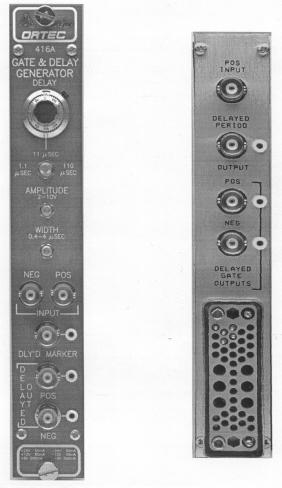
7 1 ORTEC MODEL 416A GATE AND DELAY GENERATOR 1. DESCRIPTION The ORTEC 416A Gate and Delay Generator is a single-width module that conforms to DOE/ER- 0457T. It accepts either polarity of logic pulses, provides an adjusted delay for each input pulse, and generates output pulses with both polarities that have an adjusted amplitude and width. It serves as a convenient interface between logic pulse origin and its end use. Typical applications for the 416A include gating multichannel analyzers for either coincidence or anticoincidence control, alignment of coincidence timing between two channels of information that use dissimilar pulse-shaping modes, and start and/or stop logic pulses for a time to pulse height converter. The logic pulse delay is adjustable from 0.1 through 110 :s in three overlapping ranges. The amplitude of both polarities of output pulses is adjustable within the range of 2 to 10 V. The output pulse width can be adjusted within the range of 400 ns through 4 :s. Operation is simple and reliable. The flexibility of the 416A permits it to be normalized to the input requirements of all currently available nuclear instruments and to many other applications. 2. SPECIFICATIONS 2.1. CONNECTORS Delay Nonlinearity <±2%. Delay Temperature Instability <+0.03% of adjusted Delay per C. Delay Generator Dead Time Adjusted Delay plus 200 ns on 1.1-:s range, 300 ns on 11-:s range, and 1 :s on 110-:s range. Output Generator Dead Time plus 0.2 :s. Delay Jitter <0.02% of selected range CONTROLS Adjusted Width Delay 10-turn locking potentiometer with directreading duo-dial for continuous adjustment within the range selected by the locking 3-position toggle switch: 1.1 :s Selects the range of 0.1 to 1.1 :s for the Delay potentiometer. 11 :s Selects a 1 to 11 :s range. 110 :s Selects a 1 0 to 110 :s range. Amplitude Front-panel screwdriver control permits the output pulse amplitude to be adjusted within the range of 2 to 10 V, both polarities (i.e., +2 to +10 V and -2 to -10 V). Width Front-panel screwdriver control permits the width of output pulses to be adjusted within the range of 400 ns to 4 :s INPUTS Pos Front- and rear-panel BNC connectors; +2 V pulse minimum, 12 V maximum; 100-ns minimum width, dc-coupled; impedance 1000 S. Neg Front-panel BNC connector accepts NIMstandard fast negative logic pulses; -250 mv pulse minimum; 5 ns minimum width, dc-coupled; impedance 50 S OUTPUTS Delayed Out, Pos/Neg Front- and rear-panel BNC connectors, with test points, provide simultaneous output pulses with identical characteristics except for opposite polarity; impedance <10 S. Delayed Period Rear-panel BNC connector, with test point, provides positive pulse width equal to the adjusted Delay; amplitude +5 V; rise time <50 ns; impedance <10 S.
8 2 Dly'd Marker Front-panel BNO connector, with test point, provides NIM-standard fast negative logic pulse at the end of delay time. Amplitude, -0.6 V into 50 S load; rise time <1 0 ns; width <25 ns; impedance <10 S ELECTRICAL AND MECHANICAL Power Required The Model 416A derives its power from a standard NIM bin/power supply. The power required is +24 V, 60 ma; -24 V, 60 ma; +12 V, 85 ma; and -12 V, 85 ma. Weight Net 1.3 kg (2.8 lb). Shipping 2.2 kg (4.8 lb). Dimensions NIM-standard single-width module 3.43 X cm (1.35 X in.) per DOE/ER- 0457T. 3. INSTALLATION 3.1. GENERAL The 416A Gate and Delay Generator is designed for installation and operation in an ORTEC 4000 Series Bin and Power Supply or equal. The Bin and Power Supply is designed for relay rack mounting and is usually installed in a rack that houses other electronic equipment. Therefore any vacuum tube equipment or other source of heat that operates in the same rack with the 416A must be sufficiently cooled with circulating air to prevent localized heating of the transistors and integrated circuits in the 416A. The temperature of equipment mounted in racks can easily exceed 120 F (50 C), the maximum limit for safe operation of the 416A, unless precautions are taken CONNECTION TO POWER The 416A does not contain its own power supply but obtains all the required operating power from the Bin and Power Supply in which it is installed for operation. Turn off the Bin Power supply when inserting or removing a module. The Power Supply voltages should be checked after all modules have been inserted to determine that the voltage levels remain within their rated tolerances. The 4000 Series have test points on the Power Supply control panel to permit monitoring the dc voltages easily INPUT CONNECTIONS Determine the polarity and characteristics of the input pulses that are to be furnished. Use the matching input connector on the 416A; if positive pulses are furnished, use either the front or rear panel connector and furnish the pulses through a nominal 100-S cable; if NIM-standard negative pulses are furnished, use the front panel Neg Input connector and furnish the pulses through 50-S cable OUTPUT CONNECTIONS A Delayed and Delayed Gate Output connector for each polarity is included on both the front and rear panels of the 416A for convenience. Although both polarities may be used simultaneously, the two connectors for either positive or negative polarity should not be used simultaneously. If reflections should occur in the output circuits, match the impedance of the output cable at the input of the instrument to which the pulses are furnished from the 416A.
9 3 4. OPERATING INSTRUCTIONS 4.1. GENERAL When the 416A Gate and Delay Generator is installed in the Bin and Power Supply and power is turned on, the module is ready for operation. Logic pulses are accepted through the input circuit, provided that they have the matching polarity for the input connector used and that their amplitude is sufficient to trigger a response in the 416A. A pulse source that is furnished through the Pos Input will trigger a response when its amplitude exceeds +2 V. A pulse source that is furnished through the Neg Input will trigger a response when its amplitude exceeds about -100 mv. The input pulse is delayed and then is used to generate a pair of output pulses that are identical except for polarity. The width and amplitude of the output pulses can be adjusted with front panel controls to normalize them to the intended application in a gating circuit or other similar function. In addition to the delayed output positive and negative signals that are normalized by control adjustments, there are two other output connectors for signals that are not adjustable but are typically designed to be used in nuclear instrument applications. One is the Delayed Period Output connector for which the signal rises from 0 to nominally +5 V through the adjusted delay interval. The other connector is Dly'd Marker, which furnishes a NIM-standard fast negative logic signal at the end of the adjusted delay interval MATCHING IMPEDANCE Both input and output circuits should be cabled and terminated in characteristic impedances to prevent reflections of the logic pulses. This rule is less important for positive inputs and for delayed outputs than for negative inputs and delayed marker outputs, but should be considered for all circuits when pulse fidelity is a requirement. Negative inputs and delayed marker outputs require 50-S cables and terminators for correct operation. The 416A Neg Input circuit is terminated internally with the characteristic 50-S impedance. If the Dly'd Marker output connector is used, check to see that the input impedance in the circuit that it is driving has the 50-S termination, or furnish the proper termination for the cable when it is connected. The remaining input and output circuits normally operate best with nominal 100-S cables and terminators TYPICAL APPLICATIONS Figures 4.1 through 4.3 are block diagrams for typical systems in which the 416A can be used. Figure 4.4 is a timing diagram that illustrates how the 416A can be adjusted when it is installed in the circuit of Fig These diagrams are intended as typical application arrangements but do not imply that the normalizing functions of the 416A are limited to these circuits. Use the connectors that are appropriate for the functions for which the logic outputs will be used.
10 4
11 5
12 6 5. CIRCUIT DESCRIPTION Diodes D6, D7, and D8, D9 form input protection circuits to protect the unit from large amplitude input signals. Q13, Q14, and Q15 form a dccoupled Schmitt trigger. The width of the Schmitt trigger output will be the same as the input signal or the busy time of the 416A, whichever is the longer. The current pulse at the collector of Q14 is differentiated by L2. The positive leading edge of this signal is passed by D1 to the base of Q1. Q1, Q02, Q3, Q4, and Q21 form the delay monostable multivibrator. When triggered, this multivibrator sets a voltage step onto capacitor C4, C5, C21, and C22 (depending upon range). These capacitors are then discharged with a constant current furnished by Q4. The amplitude of this current is controlled by delay potentiometer R11. Since the discharge is by a constant current, the delay will be a linear function of R11. Diode D2 provides the bias necessary to hold Q2 in the conduction state until the multivibrator is triggered, at which time the voltage pulse from the emitter of Q3 is fed through C4, C5, C21, and C22 to cut off the diode. It will remain cut off until the end of the delay period. At the end of the delay period Q21 is turned on to cause the multivibrator to recover rapidly In order to keep pileup inputs from influencing the delay period, current switch Q23, Q24 senses the busy time of the delay multivibrator and blocks the input by causing Q22 to hold the input Schmitt trigger on. The delay output pulse is fed through C3 to the delay output buffer emitter-follower Q5 and then to the delay period output. This pulse is also differentiated by L1 and fed to the base of Q6, which is a normally cutoff trailing edge of the delay period pulse. This signal is then fed to the delay marker output. The inversion of the delay marker appears on the collector of Q6 and is fed through C8 to the base of Q7. Q7, Q8, and Q9 compose the delayed gate pulse generator monostable multivibrator. When this multivibrator is triggered, the current flowing through Q8 will be switched through Q7 to Q9 and onto capacitor C11. C11, R29, and width control R28 determine the gate generator pulse width. A 20% to 100% fraction of this pulse, determined by the amplitude control R24 and trim potentiometer R25, is fed through C12 to the base of Q10. Q10 is a phase splitter which forms two pulses of equal amplitude but opposite polarity. The positive pulse appears on the emitter of Q10 and is dc-coupled to the base of Q11; the negative pulse appears on the collector of Q10 and is dc-coupled to the base of Q12. Q11 and Q12 are a NPN/PNP pair that are both in the cutoff state until the delayed gate pulse arrives, at which time they turn on for the period of the gate pulse and present the gate output to their respective output connectors. The negative input signal is coupled through the protection circuit D8, D9 to the base of Q16. Q16 and Q17 form a current switch pair that switches the current out of Q16 into Q17 when the negative threshold is exceeded. This threshold voltage is the same as the base voltage of Q17, normally!250 mv. This current is dumped on Q17 load resistor R59 and appears as a negative voltage to tunnel diode D11. D11 is normally in its low conduction state and when turned on by a pulse will switch to a negative 0.5-V state and remain for the input signal width. This signal appears on the base of Q18, which, with Q19, forms another current switch pair. Q18 is normally conducting while Q19 is cut off. When the tunnel diode D11 turns on, the negative voltage on the base of Q18 switches the current out of Q18, allowing the collector voltage to go positive. This positive voltage excursion turns on the input Schmitt trigger via Q22. Q22 performs the same functions as 013.
13 TESTING PERFORMANCE 6. MAINTENANCE AND CALIBRATION To test the operation of this unit, first test the operation of the delay multivibrator section. Insert an input trigger pulse and check for an output from the delay period output. Monitor the width of the delay period output, vary the delay potentiometer, R11, through its range, and also check the operation of the range selector switch, S1. This pulse width should be equal to the desired delay time except for a small propagation delay of about 25 ns. With the trigger present, if there is no delay period output, the trouble is immediately isolated to the delay multivibrator. Usually the first test to perform is that of measuring dc voltages and comparing them with the voltages given in Table 6.1. If this does not isolate the trouble, then use an oscilloscope for waveform checks. If the delay period output pulse is present, check for an output from the delayed marker output BNC. If the delayed marker output does not exist, then the problem is immediately isolated to the circuit surrounding Q6. If a delayed marker output exists but there is no gate pulse output, this indicates that the gate multivibrator is not being correctly triggered. Again the best test is a dc-voltage measurement test and comparison against the tabulated voltages CALIBRATION ADJUSTMENTS A trim potentiometer (R25) on the printed circuit is provided to calibrate the pulse gate output amplitude control. It should be adjusted so that the dc voltage on the collector of Q8 is +0.4 V with no signal and with amplitude control set to maximum (cw). No other adjustments are necessary DELAY RANGE CHANGES If a delay range other than 0.1 to 110 :s is desired, select one of the switch positions, and replace the selected capacity for that switch position with an amount calculated with the following formula. The new range will still have a ratio of 11:1 between its maximum and minimum limits. The formula for the replacement capacity is C = 2.5 X 10⁻⁴ X delay max where C is in farads and delay is in seconds, or C is in :F and delay is in :s GATE WIDTH RANGE CHANGES If a gate width range other than 0.4 to 4 :s is desired, replace C11 with an amount of capacity calculated with the following formula. The new range will still have a ratio of 10:1 between its maximum and minimum limits. The formula for the replacement capacity is C = 2.3 X 10⁻⁴ X width max where C is in farads and width is in seconds, or C is in :F and width is in :s. For proper operation with gate width >15 ms, C12 will require a larger value. The RC time constant of (C12) (R30) should be at least X3 of the maximum gate width FACTORY REPAIR The 416A Gate and Delay Generator can be returned to the ORTEC factory for service and repair at a nominal cost. Our standard procedure for repair ensures the same quality control and checkout that are used for a new instrument. Always contact the Customer Service Department
14 8 at ORTEC, (865) , before sending in an instrument for repair to obtain shipping instructions and so that the required Return Authorization Number can be assigned to the unit. This number should be written on the address label and on the package to ensure proper handling when it is received at the ORTEC factory.
15 9 Pins marked (*) are installed and wired in ORTEC s 4001A and 4001C Modular System Bins.
16 10
Model 9302 Amplifier-Discriminator Operating and Service Manual
 Model 9302 Amplifier-Discriminator Operating and Service Manual Printed in U.S.A. ORTEC Part No. 733690 1202 Manual Revision C Advanced Measurement Technology, Inc. a/k/a/ ORTEC, a subsidiary of AMETEK,
Model 863 Quad Timing Filter Amplifier Operating and Service Manual
 Model 863 Quad Timing Filter Amplifier Operating and Service Manual Printed in U.S.A. ORTEC Part No. 733960 0411 Manual Revision C Advanced Measurement Technology, Inc. a/k/a/ ORTEC, a subsidiary of AMETEK,
Model 113 Scintillation Preamplifier Operating and Service Manual
 Model 113 Scintillation Preamplifier Operating and Service Manual Printed in U.S.A. ORTEC Part No. 717560 1202 Manual Revision B Advanced Measurement Technology, Inc. a/k/a/ ORTEC, a subsidiary of AMETEK,
Model 9305 Fast Preamplifier Operating and Service Manual
 Model 9305 Fast Preamplifier Operating and Service Manual This manual applies to instruments marked Rev 03" on rear panel. Printed in U.S.A. ORTEC Part No.605540 1202 Manual Revision B Advanced Measurement
Model 533 Dual Sum and Invert Amplifier Operating and Service Manual
 Model 533 Dual Sum and Invert Amplifier Operating and Service Manual Printed in U.S.A. ORTEC Part No. 733410 1202 Manual Revision B Advanced Measurement Technology, Inc. a/k/a/ ORTEC, a subsidiary of AMETEK,
Model 427A Delay Amplifier Operating and Service Manual
 Model 427A Delay Amplifier Operating and Service Manual This manual Applies to instruments marked Rev 22" on rear panel Printed in U.S.A. ORTEC Part No. 733210 1202 Manual Revision B Advanced Measurement
Model 426 Linear Gate Operating and Service Manual
 Model 426 Linear Gate Operating and Service Manual This manual applies to instruments marked Rev 23" on rear panel Printed in U.S.A. ORTEC Part No. 733200 1202 Manual Revision B Advanced Measurement Technology,
Model 428 Detector Bias Supply Operating and Service Manual
 Model 428 Detector Bias Supply Operating and Service Manual Printed in U.S.A. ORTEC Part No. 733220 1202 Manual Revision C Advanced Measurement Technology, Inc. a/k/a/ ORTEC, a subsidiary of AMETEK, Inc.
ScintiPack Model 296 Photomultiplier Base with Preamplifier and High Voltage Power Supply Operating and Service Manual
 ScintiPack Model 296 Photomultiplier Base with Preamplifier and High Voltage Power Supply Operating and Service Manual WARNING This equipment generates, uses, and can radiate radio frequency energy, and
Model 449 Log/Lin Ratemeter Operating and Service Manual
 Model 449 Log/Lin Ratemeter Operating and Service Manual Printed in U.S.A. ORTEC Part No. 733270 1202 Manual Revision D Advanced Measurement Technology, Inc. a/k/a/ ORTEC, a subsidiary of AMETEK, Inc.
Model 439 Digital Current Integrator Operating Manual
 Model 439 Digital Current Integrator Operating Manual Printed in U.S.A. ORTEC Part No. 733240 0908 Manual Revision K Advanced Measurement Technology, Inc. a/k/a/ ORTEC, a subsidiary of AMETEK, Inc. WARRANTY
Model 542 Linear Gate and Stretcher Operating and Service Manual
 Model 542 Linear Gate and Stretcher Operating and Service Manual NOTE: A substitution for the dual diode package (MSD6100) may have been made in this unit. If so, two 1N4153 diodes were used to replace
Model 480 Pulser Operating and Service Manual
 Model 480 Pulser Operating and Service Manual Printed in U.S.A. ORTEC Part No. 733390 1202 Manual Revision B Advanced Measurement Technology, Inc. a/k/a/ ORTEC, a subsidiary of AMETEK, Inc. WARRANTY ORTEC*
Model 935 Quad Constant-Fraction 200-MHz Discriminator Operating and Service Manual
 Model 935 Quad Constant-Fraction 200-MHz Discriminator Operating and Service Manual U.S. Patent No. 4,179,644 Printed in U.S.A. ORTEC Part No. 753770 0503 Manual Revision H ii $GYDQFHG0HDVXUHPHQW7HFKQRORJ\,QF
Model 276L Low-Power Photomultiplier Base Operating and Service Manual
 Model 276L Low-Power Photomultiplier Base Operating and Service Manual Printed in U.S.A. ORTEC Part No. 762870 0702 Manual Revision C $GYDQFHG 0HDVXUHPHQW 7HFKQRORJ\,QF a/k/a/ ORTEC, a subsidiary of AMETEK,
Model 9307 pico-timing Discriminator Operating and Service Manual
 Model 9307 pico-timing Discriminator Operating and Service Manual Printed in U.S.A. ORTEC Part No. 764020 1202 Manual Revision C Advanced Measurement Technology, Inc. a/k/a/ ORTEC, a subsidiary of AMETEK,
Model 566 Time-to-Amplitude Converter (TAC) Operating and Service Manual
 Operating and Service Manual") Model 566 Time-to-Amplitude Converter (TAC) Operating and Service Manual Printed in U.S.A. ORTEC Part No. 678950 0411 Manual Revision F Advanced Measurement Technology, Inc. a/k/a/ ORTEC, a subsidiary
Model 566 Time-to-Amplitude Converter (TAC) Operating and Service Manual Printed in U.S.A. ORTEC Part No. 678950 0411 Manual Revision F Advanced Measurement Technology, Inc. a/k/a/ ORTEC, a subsidiary
2001A. 200KHz Function Generator Instruction Manual. 99 Washington Street Melrose, MA Phone Toll Free
 2001A 200KHz Function Generator Instruction Manual 99 Washington Street Melrose, MA 02176 Phone 781-665-1400 Toll Free 1-800-517-8431 Visit us at www.testequipmentdepot.com WARRANTY Global Specialties
Model 142AH Preamplifier Operating and Service Manual
 Model 142AH Preamplifier Operating and Service Manual Printed in U.S.A. ORTEC Part No. 733990 0202 Manual Revision B $GYDQFHG 0HDVXUHPHQW 7HFKQRORJ\,QF a/k/a/ ORTEC, a subsidiary of AMETEK, Inc. WARRANTY
INSTRUCTION MANUAL. March 11, 2003, Revision 3
 INSTRUCTION MANUAL Model 701A Stimulator March 11, 2003, Revision 3 Copyright 2003 Aurora Scientific Inc. Aurora Scientific Inc. 360 Industrial Parkway S., Unit 4 Aurora, Ontario, Canada L4G 3V7 Tel: 1-905-727-5161
PCO-7114 Laser Diode Driver Module Operation Manual
 PCO-7114 Laser Diode Driver Module Operation Manual Directed Energy, Inc. 1609 Oakridge Dr., Suite 100, Fort Collins, CO 80525, (970) 493-1901 sales@ixyscolorado.com www.ixyscolorado.com Manual Document
Model 673 Spectroscopy Amplifier and Gated Integrator Operating and Service Manual
 Model 673 Spectroscopy Amplifier and Gated Integrator Operating and Service Manual Printed in U.S.A. ORTEC Part No. 675590 0202 Manual Revision B $GYDQFHG 0HDVXUHPHQW 7HFKQRORJ\,QF a/k/a/ ORTEC, a subsidiary
Model 460 Delay Line Amplifier Operating and Service Manual
 Model 460 Delay Line Amplifier Operating and Service Manual Printed in U.S.A. ORTEC Part No. 733320 1202 Manual Revision C Advanced Measurement Technology, Inc. a/k/a/ ORTEC, a subsidiary of AMETEK, Inc.
2015 RIGOL TECHNOLOGIES, INC.
 Service Guide DG000 Series Dual-channel Function/Arbitrary Waveform Generator Oct. 205 TECHNOLOGIES, INC. Guaranty and Declaration Copyright 203 TECHNOLOGIES, INC. All Rights Reserved. Trademark Information
P5100A & P5150 High Voltage Probes Performance Verification and Adjustments
 x P5100A & P5150 High Voltage Probes Performance Verification and Adjustments ZZZ Technical Reference *P077053001* 077-0530-01 xx P5100A & P5150 High Voltage Probes Performance Verification and Adjustments
AMP-13 OPERATOR S MANUAL
 AMP-13 OPERATOR S MANUAL Version 2.0 Copyright 2008 by Vatell Corporation Vatell Corporation P.O. Box 66 Christiansburg, VA 24068 Phone: (540) 961-3576 Fax: (540) 953-3010 WARNING: Read instructions carefully
Directed Energy, Inc Oakridge Dr., Suite 100, Fort Collins, CO
 PCO-7121 Laser Diode Driver Module Operation Manual Directed Energy, Inc. 1609 Oakridge Dr., Suite 100, Fort Collins, CO 80525 sales@ixyscolorado.com www.ixyscolorado.com Contents Contents... 3 Safety...
Log Periodic Antenna
 Page 1 of 10 Log Periodic Antenna ALFM 80120 88 MHz to 108 MHz (Extendible to 80 to 120 MHz) Page 2 of 10 Table of Contents 1.0 Introduction... 3 2.0 Product Specifications... 4 3.0 Important Safety Precautions...
Glass Electrode Meter
 Glass Electrode Meter INSTRUCTION MANUAL FOR Glass Electrode R/C Meter MODEL 2700 Serial # Date PO Box 850 Carlsborg, WA 98324 U.S.A. 360-683-8300 800-426-1306 FAX: 360-683-3525 http://www.a-msystems.com
User s Guide. RP7000 Series Active Probe. Dec RIGOL Technologies, Inc.
 User s Guide RP7000 Series Active Probe Dec. 2012 RIGOL Technologies, Inc. Guaranty and Declaration Copyright 2011 RIGOL Technologies, Inc. All Rights Reserved. Trademark Information RIGOL is a registered
Model Hz to 10MHz Precision Phasemeter. Operating Manual
 Model 6610 1Hz to 10MHz Precision Phasemeter Operating Manual Service and Warranty Krohn-Hite Instruments are designed and manufactured in accordance with sound engineering practices and should give long
Signal Isolation Module. Instruction Manual SIM
 Signal Isolation Module Instruction Manual SIM200-000 Table of Contents 1. General Description... 3 2. Specifications... 3 2.1 Electrical... 3 2.2 Physical... 4 3. Installation... 4 3.1 Wiring Guidelines...
Wilcom MODEL T136BSBZW CIRCUIT TEST SET. Operating Instructions
 Wilcom MODEL T136BSBZW CIRCUIT TEST SET Operating Instructions T136BSB Current Test Set Operating Instructions 811-230-007 February 2007 Copyright (c) 2007 Wilcom All Rights reserved Wilcom reserves the
Series 3000 Model R-107A
 Series 3000 Model R-107A DUAL TONE SENDER INSTRUCTION MANUAL Monroe Electronics 100 Housel Ave Lyndonville NY 14098 800-821-6001 585-765-2254 fax 585-765-9330 monroe-electronics.com Printed in USA Copyright
Model 5100F. Advanced Test Equipment Rentals ATEC (2832) OWNER S MANUAL RF POWER AMPLIFIER
 OWNER S MANUAL RF POWER AMPLIFIER") Established 1981 Advanced Test Equipment Rentals www.atecorp.com 800-404-ATEC (2832) OWNER S MANUAL Model 5100F RF POWER AMPLIFIER 0.8 2.5 GHz, 25 Watts Ophir RF 5300 Beethoven Street Los Angeles, CA 90066
Established 1981 Advanced Test Equipment Rentals www.atecorp.com 800-404-ATEC (2832) OWNER S MANUAL Model 5100F RF POWER AMPLIFIER 0.8 2.5 GHz, 25 Watts Ophir RF 5300 Beethoven Street Los Angeles, CA 90066
Model 7000 Low Noise Differential Preamplifier
 Model 7000 Low Noise Differential Preamplifier Operating Manual Service and Warranty Krohn-Hite Instruments are designed and manufactured in accordance with sound engineering practices and should give
PDB4. Four Channel Passive Direct Box USER'S GUIDE
 PDB4 Four Channel Passive Direct Box USER'S GUIDE IMPORTANT SAFETY INSTRUCTIONS - READ FIRST This symbol, wherever it appears, alerts you to important operating and maintenance instructions in the accompanying
742A Series Resistance Standards
 742A Series Resistance Standards Instruction Manual PN 850255 September 1988 Rev. 1, 4/89 1988-2015 Fluke Corporation. All rights reserved. All product names are trademarks of their respective companies.
P5100A & P5150 High Voltage Probes Performance Verification and Adjustments
 x P5100A & P5150 High Voltage Probes Performance Verification and Adjustments ZZZ Technical Reference *P077053002* 077-0530-02 xx P5100A & P5150 High Voltage Probes Performance Verification and Adjustments
Wilcom MODEL T136BGMZW CIRCUIT TEST SET. Operating Instructions
 Wilcom MODEL T136BGMZW CIRCUIT TEST SET Operating Instructions T136BGM Current Test Set Operating Instructions 811-233-010 February 2007 Copyright (c) 2007 Wilcom All Rights reserved Wilcom reserves the
Radio Remote Controls Manual K Series
 Radio Remote Controls Manual K Series PN 52764 2010.12.20 Rev. 2 K Series radio control manual 1 Conductix Incorporated The technical data and images which appear in this manual are for informational purposes
Broadband Step-Up Transformer. User Manual
 Broadband Step-Up Transformer User Manual 990-1930 09/2004 Introduction Introduction About this unit The APC Step-Up Transformer provides 220 V power from 60 VAC Broadband cable systems. Safety Electrical
TRANSDUCER IN-LINE AMPLIFIER
 TRANSDUCER IN-LINE Voltage Model AMPLIFIER 2080 Arlingate, Columbus, Ohio 43228, (614) 850-5000 Sensotec, Inc. 2080 Arlingate Lane Columbus, Ohio 43228 Copyright 1995 by Sensotec, Inc. all rights reserved
PARALLEL MULTI-AMP KIT for 7200 Series AMPLIFIERS INSTRUCTION SHEET
 2 5 0 7 W a r r e n S t r e e t, E l k h a r t, I N 4 6 5 1 6 U S A 5 7 4. 2 9 5. 9 4 9 5 w w w. A E T e c h r o n. c o m PARALLEL MULTI-AMP KIT for 7200 Series AMPLIFIERS INSTRUCTION SHEET Kit Contents:
201AP Charge Amplifier User Manual
 Trig-Tek 201AP Charge Amplifier User Manual Publication No. 980996 Rev. A Astronics Test Systems Inc. 4 Goodyear, Irvine, CA 92618 Tel: (800) 722-2528, (949) 859-8999; Fax: (949) 859-7139 atsinfo@astronics.com
Current Probes. User Manual
 Current Probes User Manual ETS-Lindgren Inc. reserves the right to make changes to any product described herein in order to improve function, design, or for any other reason. Nothing contained herein shall
305 Stimulus Isolator. Description
 Description The Model 305 Stimulus Isolator utilizes photon coupling to provide nearly ideal isolation of the pulse and train outputs of the WPI Series 300 Anapulse Stimulators. Two Model 305 units are
INSTRUCTION MANUAL UTL260
 INSTRUCTION MANUAL UTL260 1-800-547-5740 Fax: (503) 643-6322 www.ueitest.com email: info@ueitest.com Introduction The UTL260 has all the features and measurement functions that appliance technicians need.
34134A AC/DC DMM Current Probe. User s Guide. Publication number April 2009
 User s Guide Publication number 34134-90001 April 2009 For Safety information, Warranties, Regulatory information, and publishing information, see the pages at the back of this book. Copyright Agilent
MODEL 3810/2 Line Impedance Stabilization Network
 EMC TEST SYSTEMS FEBRUARY 1996 REV C PN 399197 MODEL 3810/2 Line Impedance Stabilization Network OPERATION MANUAL USA P.O. Box 80589 Austin, Texas 78708-0589 2205 Kramer Lane, Austin, Texas 78758-4047
Analog-to-Digital-Converter User Manual
 7070 Analog-to-Digital-Converter User Manual copyright FAST ComTec GmbH Grünwalder Weg 28a, D-82041 Oberhaching Germany Version 2.0, July 7, 2005 Software Warranty FAST ComTec warrants proper operation
CSM-S USER S MANUAL TRIGGER DISTRIBUTION MODULE Release April 7, VXI Technology, Inc.
 CSM-S-11056 TRIGGER DISTRIBUTION MODULE USER S MANUAL 82-0051-000 Release April 7, 2003 VXI Technology, Inc. 2031 Main Street Irvine, CA 92614-6509 (949) 955-1894 bus 2 VXI Technology, Inc. www.vxitech.com
Owner s Manual & Safety Instructions
 Owner s Manual & Safety Instructions Save This Manual Keep this manual for the safety warnings and precautions, assembly, operating, inspection, maintenance and cleaning procedures. Write the product s
Model 1791 VHF Radio User's Manual
 Model 79 VHF Radio User's Manual ALL WEATHER INC 65 NATIONAL DRIVE SACRAMENTO, CA 95834 WWW.ALWEATHERINC.COM 79 VHF RADIO USER'S MANUAL CONTENTS INTRODUCTION... Description... Transmitter Module... Power
CURRENT MEARUREMENT SHUNT CS-10/500 USER MANUAL
 CURRENT MEARUREMENT SHUNT CS-10/500 USER MANUAL 2017 Megaimpulse Ltd. Copyright 2017 MEGAIMPULSE Ltd. All Rights Reserved. MEGAIMPULSE LTD. PROVIDES THIS MANUAL "AS IS" WITHOUT WARRANTY OF ANY KIND, EITHER
AMP-12 OPERATOR S MANUAL
 AMP-12 OPERATOR S MANUAL Version 1.0 Copyright 2002 by Vatell Corporation Vatell Corporation P.O. Box 66 Christiansburg, VA 24068 Phone: (540) 961-3576 Fax: (540) 953-3010 WARNING: Read instructions carefully
TRANSDUCER IN-LINE AMPLIFIER
 TRANSDUCER IN-LINE Bi-Polar Model AMPLIFIER 2080 Arlingate Lane, Columbus, Ohio 43228 (614) 850-5000 Sensotec, Inc. 2080 Arlingate Lane Columbus, Ohio 43228 Copyright 1995 by Sensotec, Inc. all rights
SSR-150xxx-40VL-12P-xC-xxxCS
 HELLROARING TECHNOLOGIES, INC. P.O. BOX 1521 POLSON, MT 59860 406 883-3801 HTTP://WWW.HELLROARING.COM SUPPORT@HELLROARING.COM SSR-150xxx-40VL-12P-xC-xxxCS The SSR-150xxx-40VL-12P-xC-xxxCS is designed for
User Manual. Smart-UPS On-Line. Uninterruptible Power Supply. Isolation Transformer Models: SURT001 and SURT002
 User Manual Smart-UPS On-Line Uninterruptible Power Supply Isolation Transformer Models: SURT001 and SURT002 Isolation and Step-Down Transformer Models: SURT003 and SURT004 General Information Important
Model 3725/2M. Line Impedance Stabilization Network (LISN) User Manual
 User Manual") Model 3725/2M Line Impedance Stabilization Network (LISN) User Manual ETS-Lindgren L.P. reserves the right to make changes to any product described herein in order to improve function, design, or for any
Model 3725/2M Line Impedance Stabilization Network (LISN) User Manual ETS-Lindgren L.P. reserves the right to make changes to any product described herein in order to improve function, design, or for any
PHASE ROTATION METER. Operating and Instruction Manual. a n d A C C E S S O R I E S
 PHASE ROTATION METER a n d A C C E S S O R I E S Operating and Instruction Manual HD ELECTRIC COMPANY 1 4 7 5 L A K E S I D E D R I V E WA U K E G A N, I L L I N O I S 6 0 0 8 5 U. S. A. PHONE 847.473.4980
15 Planer Stand. Model Due to continuing improvements, actual product may differ slightly from the product described herein.
 15 Planer Stand Model 96316 Assembly And Operation Instructions Due to continuing improvements, actual product may differ slightly from the product described herein. 3491 Mission Oaks Blvd., Camarillo,
Instruction Manual CT-6 High Frequency AC Current Probe
 Instruction Manual CT-6 High Frequency AC Current Probe 071-0453-00 Revision A Copyright Tektronix, Inc. All rights reserved. Tektronix products are covered by U.S. and foreign patents, issued and pending.
SUBNANOSECOND PULSE GENERATOR PPG-2/1000 USER MANUAL
 SUBNANOSECOND PULSE GENERATOR PPG-2/1000 USER MANUAL 2015 Megaimpulse Ltd. Copyright 2015 MEGAIMPULSE Ltd. All Rights Reserved. MEGAIMPULSE LTD. PROVIDES THIS MANUAL "AS IS" WITHOUT WARRANTY OF ANY KIND,
User Guide. Digital AC/DC Clamp Meter Model 38394
 User Guide Digital AC/DC Clamp Meter Model 38394 Introduction Congratulations on your purchase of Extech s 38394 AC/DC Clamp Meter. This clamp meter measures AC/DC Current to 600A, DC/AC Voltage, Resistance,
Model 855 Dual Spectroscopy Amplifier Operating and Service Manual
 Model 855 Dual Spectroscopy Amplifier Operating and Service Manual This manual applies to instruments marked Rev. 03" on rear panel. Printed in U.S.A. ORTEC Part No. 717490 0406 Manual Revision C $GYDQFHG0HDVXUHPHQW7HFKQRORJ\,QF
HP 86290B RF PLUG-IN GHz HEWLETT PACKARD
 OPERATING AND SERVICE MANUAL. HP 86290B RF PLUG-IN 2.0-18.6 GHz HEWLETT PACKARD COPYRIGHT AND DISCLAIMER NOTICE Copyright - Agilent Technologies, Inc. Reproduced with the permission of Agilent Technologies
User s Guide. Digital AC/DC Clamp Meter Model 38394
 User s Guide Digital AC/DC Clamp Meter Model 38394 Introduction Congratulations on your purchase of Extech s 38394 AC/DC Clamp Meter. This clamp meter measures AC/DC Current to 600A, DC/AC Voltage, Resistance,
TA MHz oscilloscope probe TA MHz oscilloscope probe
 TA375 100 MHz oscilloscope probe TA386 200 MHz oscilloscope probe User's Guide X1 X10 TA386 X1/X10 Max. 600 Vp Introduction This passive high-impedance oscilloscope probe is suitable for most oscilloscopes
LUDLUM MODEL 182 RADON FLASK COUNTER. June 2011 Serial Number PR and Succeeding Serial Numbers
 LUDLUM MODEL 182 RADON FLASK COUNTER June 2011 Serial Number PR206794 and Succeeding Serial Numbers LUDLUM MODEL 182 RADON FLASK COUNTER June 2011 Serial Number PR206794 and Succeeding Serial Numbers LUDLUM
Model MV106J/MV116J. ±10nVdc to ±11Vdc Precision DC Voltage Standard Source. Operating Manual
 Model MV106J/MV116J ±10nVdc to ±11Vdc Precision DC Voltage Standard Source Operating Manual This page intentionally left blank. MV 106 & MV116 OPERATORS MANUAL Serial No. Win-man\mvman.wpd This page intentionally
Master Reference Unit
 Master Reference Unit Instruction Manual Model D10096-000 Driven by Excellence D.C. DRIVES, A.C. INVERTERS, SOLID STATE STARTERS, SYSTEM INTERFACE CIRCUITS AND ENGINEERED SYSTEMS Driven by Excellence D.C.
TETRIS User's Guide. High Impedance Active Probe DO177-1
 TETRIS 1500 High Impedance Active Probe User's Guide DO177-1 TETRIS 1500 Copyright 2010 Ltd. All rights reserved. Information in this publication supersedes that in all previously published material. Specifications
INSTRUCTION SHEET STRUT DRIVER RETROFIT KIT PN: 22-79SDRF
 INSTRUCTION SHEET STRUT DRIVER RETROFIT KIT PN: 22-79SDRF COMPONENTS: - Note: Each kit comes with one Strut Driver Gear Case Assembly, one Strut Driver Tube End Adapter Assembly, and a One-Time-Use Threadlocker
COMBILOG ANTENNA MODEL AC MHz. rev: 0202
 COMBILOG ANTENNA 30-2000 MHz MODEL AC-220 rev: 0202 WARRANTY All equipment manufactured by Com-Power Corporation is warranted against defects in material and workmanship for a period of two (2) years from
BC145 SIGNAL ISOLATOR BOARD
 BC145 SIGNAL ISOLATOR BOARD 4/17 Installation & Operating Manual MN1373 Any trademarks used in this manual are the property of their respective owners. Important: Be sure to check www.baldor.com to download
LUDLUM MODEL 421 AND PMT BASE WITH PREAMPLIFIER/BIAS SUPPLY. October 2014 Serial Number and Succeeding Serial Numbers
 LUDLUM MODEL 421 AND 421-3 PMT BASE WITH PREAMPLIFIER/BIAS SUPPLY October 2014 Serial Number 200000 and Succeeding Serial Numbers LUDLUM MODEL 421 AND 421-3 PMT BASE WITH PREAMPLIFIER/BIAS SUPPLY October
MODEL W Power Amplifier
 TEGAM, INC. MODEL 2348 18.75 W Power Amplifier This owner s manual was as current as possible when this product was manufactured. However, products are constantly being updated and improved. Because of
Planishing hammer stand For use with SKU Planishing hammer
 Planishing hammer stand For use with SKU 94847 Planishing hammer Model 96300 Assembly And Operation Instructions Please Note: Planishing Hammer not included with Stand. Due to continuing improvements,
OPERATION & SERVICE MANUAL FOR FC 110 AC POWER SOURCE
 OPERATION & SERVICE MANUAL FOR FC 100 SERIES AC POWER SOURCE FC 110 AC POWER SOURCE VERSION 1.3, April 2001. copyright reserved. DWG No. FC00001 TABLE OF CONTENTS CHAPTER 1 INTRODUCTION... 1 1.1 GENERAL...
10 Amp Digital PWM Motor Speed Controller CV-2110-HD and CV-2110-HDS
 10 Amp Digital PWM Motor Speed Controller CV-2110-HD and CV-2110-HDS The Analog / Digital PWM controller allows you to control the speed of a motor, brightness of a lamp or other device using an analog
Model 3210C. 100 Ampere AC Current Standard. Operating Manual
 Model 3210C 100 Ampere AC Current Standard Operating Manual This page intentionally left blank. 3210C OPERATORS MANUAL Serial No. Win-man\3210C.wpd This page intentionally left blank. 3210C OPERATORS MANUAL
41P Portable Calibrator User Manual
 Trig-Tek 41P Portable Calibrator User Manual Publication No. 980961 Rev. A Astronics Test Systems Inc. 4 Goodyear, Irvine, CA 92618 Tel: (800) 722-2528, (949) 859-8999; Fax: (949) 859-7139 atsinfo@astronics.com
15 Amp Digital High Frequency PWM Motor Speed Controller SPD-315-D and SPD-315-DS
 15 Amp Digital High Frequency PWM Motor Speed Controller SPD-315-D and SPD-315-DS The SPD-315-D(S) PWM controller allows you to control the speed of a motor, brightness of a lamp or other load using a
User s Guide. Agilent 16441A R-Box. Agilent Part No Printed in Japan January Edition 4
 User s Guide Agilent 16441A R-Box Agilent Part No. 16441-90000 Printed in Japan January 2000 Edition 4 Legal Notice The information contained in this document is subject to change without notice. Copyright
DUAL CHANNEL BROADBAND LINEAR AMPLIFIER Model A800D
 DUAL CHANNEL BROADBAND LINEAR AMPLIFIER Model A800D HIGH VOLTAGE FIXED GAIN BROADBAND 800Vpp 60mA 100x DC to ca 200 khz LOW OUTPUT IMPEDANCE HIGH SLEW RATE
SSR VL-12P-xC-NCS
 HELLROARING TECHNOLOGIES, INC. P.O. BOX 1521 POLSON, MT 59860 406 883-3801 HTTP://WWW.HELLROARING.COM SUPPORT@HELLROARING.COM SSR-40150-200VL-12P-xC-NCS The SSR-40150-200VL-12P-xC-NCS is designed for Low
Copyright 2014 by Minarik Drives
 Copyright 2014 by Minarik Drives All rights reserved. No part of this document may be reproduced or transmitted in any form without written permission from Minarik Drives. The information and technical
An American Control Electronics Brand PCM4 SERIES USER MANUAL PCM4.
 An American Control Electronics Brand PCM4 SERIES PCM4 USER MANUAL www.minarikdrives.com Dear Valued Consumer: Congratulations on your purchase of the PCM4 Series isolation card. This User Manual was created
Owner s Manual & Safety Instructions
 Owner s Manual & Safety Instructions Save This Manual Keep this manual for the safety warnings and precautions, assembly, operating, inspection, maintenance and cleaning procedures. Write the product s
GT-1050A 2 GHz to 50 GHz Microwave Power Amplifier
 Established 1981 Advanced Test Equipment Rentals www.atecorp.com 800-404-ATEC (2832) Giga-tronics GT-1050A Microwave Power Amplifier GT-1050A 2 GHz to 50 GHz Microwave Power Amplifier Operation Manual
ATV CULTIVATOR OWNER S MANUAL
 ATV CULTIVATOR OWNER S MANUAL WARNING: Read carefully and understand all ASSEMBLY AND OPERATION INSTRUCTIONS before operating. Failure to follow the safety rules and other basic safety precautions may
ADA416-XLR DISTRIBUTION AMPLIFIERS OPERATING AND MAINTENANCE MANUAL
 ADA416-XLR DISTRIBUTION AMPLIFIERS OPERATING AND MAINTENANCE MANUAL Copyright 2015, ATI Audio Inc. DESCRIPTION Your ADA416-XLR provides four independent one-in by four-out circuit groups. A four-output
Smart-UPS On-Line Isolation and Step-Down Transformer SRT5KTF
 Smart-UPS On-Line Isolation and Step-Down Transformer SRT5KTF Safety Messages Read the instructions carefully to become familiar with the equipment before attempting to install, operate, service or maintain
Current Probe Fixture Instruction Manual
 Current Probe Fixture Instruction Manual 1 TABLE OF CONTENTS INTRODUCTION 3 GENERAL INFORMATION 4 TEST METHODS 5 SAFETY 7 FIGURES 8 FORMULAS 10 MAINTENANCE 11 WARRANTY 12 2 INTRODUCTION figure 1 Mechanical
INSTALLATION GUIDE. Video Balun Transceiver with fixed BNC for twisted pair operation with other balun transceivers or active receivers.
 INSTALLATION GUIDE VB37M Video Balun Transceiver for Twisted Pair Description Video Balun Transceiver with fixed BNC for twisted pair operation with other balun transceivers or active receivers. The VB37M
200B Clipper Module User Manual
 Trig-Tek 200B Clipper Module User Manual Publication No. 980954 Rev. A Astronics Test Systems Inc. 4 Goodyear, Irvine, CA 92618 Tel: (800) 722-2528, (949) 859-8999; Fax: (949) 859-7139 atsinfo@astronics.com
RIGOL. User s Guide. RP5600 Passive Probe. July 2010 RIGOL Technologies, Inc.
 User s Guide RP5600 Passive Probe July 2010 RIGOL Technologies, Inc. Guaranty and Declaration Copyright 2010 RIGOL Technologies, Inc. All Rights Reserved. Trademark Information RIGOL is a registered trademark
BROADBAND LINEAR AMPLIFIER Model P150
 ELECTRONICS AB BROADBAND LINEAR AMPLIFIER Model P150 HIGH VOLTAGE GAIN HIGH CURRENT +150V 20x 1A HIGH POWER SMALL SIGNAL SLEW RATE BANDWIDTH BANDWIDTH 30 V/µs DC to ca 60 khz DC to >200 khz FLC Electronics
User s Guide RIGOL. PA1000 Series Power Amplifier. Publication number: UGF Mar RIGOL TECHNOLOGIES, INC. All Rights Reserved.
 User s Guide Publication number: UGF01103-1110 Mar. 2017 PA1000 Series Power Amplifier 2009 TECHNOLOGIES, INC. All Rights Reserved. Copyright Information 2009 TECHNOLOGIES, INC. All Rights Reserved. products