Model 428 Detector Bias Supply Operating and Service Manual
|
|
|
- Gertrude Carr
- 5 years ago
- Views:
Transcription
1 Model 428 Detector Bias Supply Operating and Service Manual Printed in U.S.A. ORTEC Part No Manual Revision C
2 Advanced Measurement Technology, Inc. a/k/a/ ORTEC, a subsidiary of AMETEK, Inc. WARRANTY ORTEC* warrants that the items will be delivered free from defects in material or workmanship. ORTEC makes no other warranties, express or implied, and specifically NO WARRANTY OF MERCHANTABILITY OR FITNESS FOR A PARTICULAR PURPOSE. ORTEC s exclusive liability is limited to repairing or replacing at ORTEC s option, items found by ORTEC to be defective in workmanship or materials within one year from the date of delivery. ORTEC s liability on any claim of any kind, including negligence, loss, or damages arising out of, connected with, or from the performance or breach thereof, or from the manufacture, sale, delivery, resale, repair, or use of any item or services covered by this agreement or purchase order, shall in no case exceed the price allocable to the item or service furnished or any part thereof that gives rise to the claim. In the event ORTEC fails to manufacture or deliver items called for in this agreement or purchase order, ORTEC s exclusive liability and buyer s exclusive remedy shall be release of the buyer from the obligation to pay the purchase price. In no event shall ORTEC be liable for special or consequential damages. Quality Control Before being approved for shipment, each ORTEC instrument must pass a stringent set of quality control tests designed to expose any flaws in materials or workmanship. Permanent records of these tests are maintained for use in warranty repair and as a source of statistical information for design improvements. Repair Service If it becomes necessary to return this instrument for repair, it is essential that Customer Services be contacted in advance of its return so that a Return Authorization Number can be assigned to the unit. Also, ORTEC must be informed, either in writing, by telephone [(865) ] or by facsimile transmission [(865) ], of the nature of the fault of the instrument being returned and of the model, serial, and revision ("Rev" on rear panel) numbers. Failure to do so may cause unnecessary delays in getting the unit repaired. The ORTEC standard procedure requires that instruments returned for repair pass the same quality control tests that are used for new-production instruments. Instruments that are returned should be packed so that they will withstand normal transit handling and must be shipped PREPAID via Air Parcel Post or United Parcel Service to the designated ORTEC repair center. The address label and the package should include the Return Authorization Number assigned. Instruments being returned that are damaged in transit due to inadequate packing will be repaired at the sender's expense, and it will be the sender's responsibility to make claim with the shipper. Instruments not in warranty should follow the same procedure and ORTEC will provide a quotation. Damage in Transit Shipments should be examined immediately upon receipt for evidence of external or concealed damage. The carrier making delivery should be notified immediately of any such damage, since the carrier is normally liable for damage in shipment. Packing materials, waybills, and other such documentation should be preserved in order to establish claims. After such notification to the carrier, please notify ORTEC of the circumstances so that assistance can be provided in making damage claims and in providing replacement equipment, if necessary. Copyright 2002, Advanced Measurement Technology, Inc. All rights reserved. *ORTEC is a registered trademark of Advanced Measurement Technology, Inc. All other trademarks used herein are the property of their respective owners.
3 iii CONTENTS WARRANTY... ii SAFETY INSTRUCTIONS AND SYMBOLS... iv SAFETY WARNINGS AND CLEANING INSTRUCTIONS... v 1. DESCRIPTION SPECIFICATIONS INSTALLATION GENERAL CONNECTION TO POWER CONNECTIONS TO THE OPERATING INSTRUCTIONS INITIAL TESTING POLARITY SELECTION BIAS VOLTAGE INDICATOR LIGHT BIAS VOLTAGE SELECTORS CURRENT MONITOR JACKS UNDESIRABLE LEAKAGE CURRENTS DETERMINATION OF ACTUAL DETECTOR BIAS GUARD-RING VOLTAGE SUPPLY DETECTOR CONSIDERATIONS AT HIGH BIAS VOLTAGES MAINTENANCE TESTING PERFORMANCE OF BIAS SUPPLY ADJUSTMENTS TROUBLESHOOTING SUGGESTIONS REPAIRS... 6
4 iv SAFETY INSTRUCTIONS AND SYMBOLS This manual contains up to three levels of safety instructions that must be observed in order to avoid personal injury and/or damage to equipment or other property. These are: DANGER WARNING CAUTION Indicates a hazard that could result in death or serious bodily harm if the safety instruction is not observed. Indicates a hazard that could result in bodily harm if the safety instruction is not observed. Indicates a hazard that could result in property damage if the safety instruction is not observed. Please read all safety instructions carefully and make sure you understand them fully before attempting to use this product. In addition, the following symbol may appear on the product: ATTENTION Refer to Manual DANGER High Voltage Please read all safety instructions carefully and make sure you understand them fully before attempting to use this product.
5 v SAFETY WARNINGS AND CLEANING INSTRUCTIONS DANGER Opening the cover of this instrument is likely to expose dangerous voltages. Disconnect the instrument from all voltage sources while it is being opened. WARNING Using this instrument in a manner not specified by the manufacturer may impair the protection provided by the instrument. Cleaning Instructions To clean the instrument exterior:! Unplug the instrument from the ac power supply.! Remove loose dust on the outside of the instrument with a lint-free cloth.! Remove remaining dirt with a lint-free cloth dampened in a general-purpose detergent and water solution. Do not use abrasive cleaners. CAUTION To prevent moisture inside of the instrument during external cleaning, use only enough liquid to dampen the cloth or applicator.! Allow the instrument to dry completely before reconnecting it to the power source.
6 vi
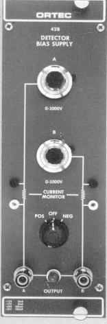
7 1 ORTEC MODEL 428 DETECTOR BIAS SUPPLY 1. DESCRIPTION The ORTEC 428 Detector Bias Supply provides bias voltage of either polarity for two semiconductor detectors. The voltages are selected independently by 10-turn, direct-reading potentiometers. The polarity is controlled by a front panel switch. Jacks are provided on the front panel for external monitoring of the current in each detector. The output of the 428 is short-circuit proof and has an impedance of approximately 1.3 MS. The 428 is a double-width module designed to meet the recommended standards outlined in DOE Report TID (Rev.). It receives the necessary operating power from the ORTEC 4001/4002 Bin and Power Supply through the rear module connector. WARNING This instrument produces voltages that can be hazardous. Always have power switched off before connecting or removing cables to or from the 428 and the units to which its high voltage outputs are applied. Observe the same precautions when using the test points for any purpose. 2. SPECIFICATIONS PERFORMANCE NOISE AND RIPPLE <0.0002% TEMPERATURE STABILITY 50 C. 0.03%/ C, 0 to LINE STABILITY Directly proportional to dc power supply stability (<0.02% for 105 to 125 V ac when using ORTEC 4002A). CONTROLS BIAS CONTROLS (A and B) 10-turn directreading potentiometers. POS/OFF/NEG Front panel switch to control bias polarity. Off position provides standby condition for the power supply. OUTPUTS OUTPUTS A AND B Two independent circuits, short-circuit proof, with front panel SHV connector; range 0 to 1000V; polarity positive or negative (both outputs same polarity), selectable by front panel Pos/Off/Neg switch. Output impedance -1.3 MS. CURRENT MONITOR Front panel jacks for external monitoring of the current in each detector. ELECTRICAL AND MECHANICAL POWER REQUIREMENTS +24 V, 165 ma; -24 V, 165 ma. WEIGHT (Shipping) 7 lb, 4 oz (3.3 kg). WEIGHT (Net) 4 lb (1.82 kg). DIMENSIONS NIM-standard double-width module (2.70 by in.) Per TID (Rev.) RELATED EQUIPMENT The 428 is compatible with ORTEC detectors and ORTEC preamplifiers that have provisions for an external detector bias voltage.
8 2 3. INSTALLATION 3.1. GENERAL The 428 contains an internal power supply that must be used in conjunction with a Nuclear- Standard Bin and Power Supply such as the ORTEC 4001/4002. The 428 is intended for rack mounting; therefore if vacuum tube equipment is operated in the same rack, there must be sufficient cooling air circulating to prevent any localized heating of the all-transistor circuitry used throughout the module. The temperature of equipment mounted in racks can easily exceed the recommended maximum unless this precaution is taken. The 428 should not be subjected to temperatures in excess of 120 F (50 C) CONNECTION TO POWER Turn off power when inserting or removing modules. The ORTEC 4000 Series is designed so that it is not possible to overload the Bin Power Supply with a full complement of modules in the Bin; since, however, this may not be true when the Bin contains modules other than those of ORTEC design, the Power Supply voltages should be checked after the modules are inserted. The ORTEC 4001/4002 has test points on the Power Supply control panel to monitor the dc voltages CONNECTIONS TO THE 428 The ORTEC 428 is compatible with ORTEC detectors and with preamplifiers that have provisions to accept bias voltage for the detector. All operating controls and bias voltage output connectors are located on the front panel. The output connectors are the type SHV and are not compatible with ordinary BNC connectors. A perforated shield encloses the unit so that high voltages are not exposed. WARNING Do not operate this unit without the protective covers, since lethal voltages are exposed inside the instrument. Tip jacks are provided for monitoring the current in each detector. See Section 4.5 for information on appropriate dc meters. Always have power for the 428 turned off before connecting or removing meter leads. Any meter used as a current monitor is connected in shunt with 1 MS on the output circuit, and reduces the output impedance. 4. OPERATING INSTRUCTIONS 4.1. INITIAL TESTING Refer to Section 5.1 of this manual for information concerning testing performance POLARITY SELECTION The Polarity Switch is located on the front panel and also serves as an On-Off switch for power to the 428. When changing the polarity of the output bias voltage, stop the switch in the Off position for a few seconds before switching to the other polarity. This pause in the Off position is necessary to allow the ac starting circuit for the dc to dc converter to recharge BIAS VOLTAGE INDICATOR LIGHT The Bias Voltage indicator light is a neon light located between the two front panel SHV output connectors and indicates that the power is turned on. If the 428 is turned on and the Bias Voltage indicator light does not illuminate, turn the Polarity Selection switch to the Off position for approximately 2 sec and then return it to the desired polarity. This pause in the Off position is necessary to allow the ac starting circuit for the dc to dc converter to recharge.
9 BIAS VOLTAGE SELECTORS The desired bias voltage for each output is selected by its associated 10-turn potentiometer. The voltage at each output is read directly from its corresponding dial. The 10-turn potentiometers have a linearity of ±0.25%. The output impedance is approximately 1.3 MS, which will normally be negligible compared to the detector load resistor in the preamplifier. This resistor typically ranges from 22 to 2000 MS. The voltage at the output connector of the 428 can be calculated by the formula V o = V dial - I D (1.3 x 10 6 ), where V o = output voltage, V dial = voltage indicated by 10-turn dial, and I D = detector current. The output impedance of this unit can be decreased bv methods given in Section CURRENT MONITOR JACKS Tip jacks are provided on the front panel as a convenience for monitoring each detector current. Typical leakage currents for ordinary roomtemperature surface-barrier detectors range from 0.1 to 1 :A. Semiconductor detectors cooled to liquid nitrogen temperature have leakage currents ranging from 0.1 to 10 na. This current is measured by connecting a floating ammeter or voltmeter to the Current Monitoring jacks as shown in Fig If an electronic type of meter operated from the power line is used, the input circuit must be capable of floating above earth and power line ground so that the leakage to ground does not load the bias supply. The low impedance side of the meter must be connected to the black tip jack rather than to the white jack; otherwise, the leakage current of the instrument from the low terminal to power line ground will be indicated incorrectly as detector current. If the detector current is measured with an ammeter, where 1 D = detector current, I M =ammeter current, and R S = input resistance of ammeter. If R S is very much less than 1 MS, the meter current can be interpreted as detector current. Since the smaller R S is connected directly in parallel with 1 MS of the output circuit, Z o is reduced. When a voltmeter is used to measure the detector current, where 1 D = detector current, V M =measured voltage, and R p = input resistance of voltmeter. If R p is much greater than 1 MS, then I D = V M x 10 6 ampere. If a meter that will not float above powerline and chassis ground is used to measure the detector current, it should be a microammeter connected as shown in Fig Do not use the current monitor jacks unless the meter can be isolated from ground. Fig Semiconductor Detector Bias and Current Measuring Circuit Using a Floating Meter.
10 DETERMINATION OF ACTUAL DETECTOR BIAS In addition to its use as an indicator of physical condition of the detector, the detector current allows accurate determination of the actual bias voltage across the detector, This actual voltage differs from that indicated by the bias selector dials by the amount of drop in voltage across the detector load and filter resistors due to the detector current. Accurate determination of actual detector voltage is important, since it is an important parameter in both the depleted (sensitive) depth of the detector and the collecting field strength. Fig Semiconductor Detector Bias and Current Measuring Circuit Using a Nonfloating Meter UNDESIRABLE LEAKAGE CURRENTS Teflon-insulated current monitoring jacks and SHV connectors are used in an effort to reduce leakage currents to a minimum in the 428. Insulation resistance of 1 x S or greater is desirable to measure a detector leakage current of 1 na at 1000 V. In order to maintain insulation resistances of this magnitude, the insulators will have to be cleaned frequently. Either Freon or methly alcohol is a good cleaning agent. It may not be practical to reduce the leakage in external cables and connections to a negligible magnitude. In such cases it may suffice to note the residual leakage current with all wiring in place except the detector itself, and then subtract this residual current from the indicated current to obtain the actual detector current. If the leakage phenomenon is essentially a resistance, then its value may be computed from Ohm's law for use in determining the residual current at various voltages, without the necessity of actual measurements. To obtain the actual detector voltage, one must know the sum of all series resistances in the circuit between voltage source and detector. The resistance of the internal circuit of the 428 may be approximated by 1.3 MS, unless this has been reduced by a current monitor (Section 4.5). Detector load resistors may vary from 10 MS to 200 MS in ordinary applications, and may be several thousand megohms in special applications involving cooled detectors. In addition, there is usually a filter resistor of 1 MS or more near and in series with the load resistor. The values of these resistors can usually be ascertained from the schematic diagram of the preamplifier used. Once having determined the total series resistance, the loss of bias in that resistance can be calculated by Ohm's law GUARD-RING VOLTAGE SUPPLY When detectors that require a separate bias connection to a guard ring are used, the 428 will prove convenient in that the signal electrode bias can be taken from one bias output connector and the guard-ring potential taken from the other. In this way the two potentials can be varied independently of each other to determine the optimum biasing condition. The usual optimum is obtained when both are nearly the same, but a small difference is sometimes beneficial. In general, that setting which minimizes the signal electrode current will be near optimum.
11 DETECTOR CONSIDERATIONS AT HIGH BIAS VOLTAGES Semiconductor radiation detectors that utilize more than a few hundred volts bias generally require some care in the application of that bias to reduce the risk of damaging the detector. It is helpful to observe the noise output of the main amplifier with an oscilloscope while the bias voltage is advanced. Small breakdown phenomena which die out in in less than a minute can be observed after a bias increase. For greatest safety, it is advisable to approach the final operating bias in small increments, with brief aging periods between increments. 5. MAINTENANCE 5.1. TESTING PERFORMANCE OF BIAS SUPPLY The following paragraphs are intended as aids in the installation and checkout of the 428. These instructions include information on the front panel controls, output voltages, and internal adjustments. The following or equivalent test equipment is needed: Nuclear-Standard Bin and Power Supply, such as the ORTEC 4001/4002. Oscilloscope with an input coupling capacitor rated at more than 500 V. Voltmeter with input impedance of 100 MS or greater on the 1000-V scale. Before making the performance tests, take the following preliminary steps: 1. Visually check the module for possible damage due to shipment. 2. Connect ac power to Nuclear Standard Bin, ORTEC 4001/ Plug module into Bin and check for proper mechanical alignment. 4. Ensure that the Polarity Selection switch on the ORTEC 428 is in the Off position. 5. Switch on the ac power and check the dc Power Supply. voltages at the test points on the 401 Power Supply control panel. To check the performance of the 428, make the following tests: 1. Set the bias selector potentiometers to zero. 2. Set the voltmeter to the 1000-V scale and connect it to output A. 3. Rotate the Polarity Selection switch to Pos. 4. Increase the potentiometer associated with output A to 1000 and check the output voltage for approximately 1000 V. The loading effect of the voltmeter on the circuit should be considered. For example, a voltmeter with an input impedance of 100 MS will produce a 10-:A current drain on the output. This output current will produce an 11-V drop across the series. 1.1-MS output resistance (R15 and R18); therefore the voltmeter should read 989 V. If the output voltage is not in agreement with the dial reading, see Section 6.2 for calibration procedure. 5. Reduce the potentiometer back to zero and check the potentiometer linearity by comparing the output voltage versus the potentiometer dial reading. 6. Connect the voltmeter to output 8 and repeat steps 4 and Turn the Polarity-Selection switch to Off for about 2 sec and then to Neg and repeat steps 4, 5, and Set the output voltage to zero and connect output A to the ac-coupled input of an oscilloscope with a coaxial cable. Increase the output voltage to 500 V and check the ripple. It should be less than 1 mv peak to peak.
12 ADJUSTMENTS If the output voltage does not agree with the dial reading, it should be recalibrated using the following procedure: 1. Ensure that the 428 Polarity Selection switch is in the Off position. 2. Apply power to the 428 through a 401 C-3 or equivalent extender cable. (The module must be out of the Bin when this adjustment is made.) 3. Switch on the ac power and check the dc Power Supply voltages at the test points on the 4002 Power Supply control panel. 4. Select the 1000-V scale on a voltmeter and connect it to output A. The input impedance of the voltmeter should be 100 MS or greater on this scale. 5. Rotate the Polarity Selection switch to Pos. 6. Increase the potentiometer associated with output A to 1000 and check the output voltage for approximately 1000 V. The loading effect of the voltmeter on the circuit should be considered before the voltage is adjusted. For example, a voltmeter with an input impedance of 100 MS will produce a 10-:A current drain on the output. This output current will produce an 11-V drop across the series 1.1-MS output resistance (R15 and R18); therefore the voltmeter should read 989 V. 7. If the voltmeter does not read 989 V, calibrate the output voltage by adjusting resistor R12. Access to R12 is available through a hole in the top cover of the module. CAUTION: Use only an insulated screwdriver to make this adjustment, as lethal voltages exist inside. This adjustment will calibrate the unit for both positive and negative polarity. 8. Reduce the potentiometer to zero and check the output voltage versus the potentiometer dial reading at several points. Resistors R15 and R 17 provide a method of measuring the detector current with a voltmeter. (See Section 4.5 for details.) If these resistors are shorted the output impedance will be reduced by 1 MS. Resistors R 18 and R 19 limit the current at the current monitoring jacks and prevent these voltages from being lethal. The output impedance will be reduced to 110 K, but the voltages at the current monitoring jacks will be, lethal because they are not protected by current limiters TROUBLESHOOTING SUGGESTIONS 1. Ensure that the proper dc voltage is supplied to the module. 2. Turn the Polarity Selection switch to the Off position for approximately 2 sec and ensure that the output is not shorted. 3. Return the Polarity Selection switch to the desired polarity. 4. Transistors Q1 and Q2 have been selected for a V cbo greater than 140 V. Replacement transistors should be selected for the same high V cbo REPAIRS This instrument can be returned to the ORTEC factory for service and repair at a nominal cost. Our standard procedure for repair ensures the same quality control and checkout that are used for a new instrument. Always contact Customer Services at ORTEC, (865) , before sending in an instrument for repair to obtain shipping instructions and so that the required Return Authorization Number can be assigned to the unit. Write this number on the address label and on the package to ensure prompt attention when it reaches the ORTEC factory.
13 7 Bin/Module Connector Pin Assignments For Standard Nuclear Instrument Modules per DOE/ER-0457T. Pin Function Pin Function 1 +3 V 23 Reserved 2-3 V 24 Reserved 3 Spare bus 25 Reserved 4 Reserved bus 26 Spare 5 Coaxial 27 Spare 6 Coaxial * V 7 Coaxial *29-24 V V dc 30 Spare bus 9 Spare 31 Spare *10 +6 V 32 Spare *11-6 V * V ac (hot) 12 Reserved bus *34 Power return ground 13 Spare 35 Reset (Scaler) 14 Spare 36 Gate 15 Reserved 37 Reset (Auxiliary) * V 38 Coaxial *17-12 V 39 Coaxial 18 Spare bus 40 Coaxial 19 Reserved bus * V ac (neutral) 20 Spare *42 High-quality ground 21 Spare G Ground guide pin 22 Reserved Pins marked (*) are installed and wired in ORTEC s 4001A and 4001C Modular System Bins.
Model 9302 Amplifier-Discriminator Operating and Service Manual
 Model 9302 Amplifier-Discriminator Operating and Service Manual Printed in U.S.A. ORTEC Part No. 733690 1202 Manual Revision C Advanced Measurement Technology, Inc. a/k/a/ ORTEC, a subsidiary of AMETEK,
Model 113 Scintillation Preamplifier Operating and Service Manual
 Model 113 Scintillation Preamplifier Operating and Service Manual Printed in U.S.A. ORTEC Part No. 717560 1202 Manual Revision B Advanced Measurement Technology, Inc. a/k/a/ ORTEC, a subsidiary of AMETEK,
Model 533 Dual Sum and Invert Amplifier Operating and Service Manual
 Model 533 Dual Sum and Invert Amplifier Operating and Service Manual Printed in U.S.A. ORTEC Part No. 733410 1202 Manual Revision B Advanced Measurement Technology, Inc. a/k/a/ ORTEC, a subsidiary of AMETEK,
Model 863 Quad Timing Filter Amplifier Operating and Service Manual
 Model 863 Quad Timing Filter Amplifier Operating and Service Manual Printed in U.S.A. ORTEC Part No. 733960 0411 Manual Revision C Advanced Measurement Technology, Inc. a/k/a/ ORTEC, a subsidiary of AMETEK,
Model 9305 Fast Preamplifier Operating and Service Manual
 Model 9305 Fast Preamplifier Operating and Service Manual This manual applies to instruments marked Rev 03" on rear panel. Printed in U.S.A. ORTEC Part No.605540 1202 Manual Revision B Advanced Measurement
Model 416A Gate and Delay Generator Operating and Service Manual
 Model 416A Gate and Delay Generator Operating and Service Manual Printed in U.S.A. ORTEC Part No. 733160 1202 Manual Revision E Advanced Measurement Technology, Inc. a/k/a/ ORTEC, a subsidiary of AMETEK,
Model 427A Delay Amplifier Operating and Service Manual
 Model 427A Delay Amplifier Operating and Service Manual This manual Applies to instruments marked Rev 22" on rear panel Printed in U.S.A. ORTEC Part No. 733210 1202 Manual Revision B Advanced Measurement
Model 439 Digital Current Integrator Operating Manual
 Model 439 Digital Current Integrator Operating Manual Printed in U.S.A. ORTEC Part No. 733240 0908 Manual Revision K Advanced Measurement Technology, Inc. a/k/a/ ORTEC, a subsidiary of AMETEK, Inc. WARRANTY
Model 426 Linear Gate Operating and Service Manual
 Model 426 Linear Gate Operating and Service Manual This manual applies to instruments marked Rev 23" on rear panel Printed in U.S.A. ORTEC Part No. 733200 1202 Manual Revision B Advanced Measurement Technology,
ScintiPack Model 296 Photomultiplier Base with Preamplifier and High Voltage Power Supply Operating and Service Manual
 ScintiPack Model 296 Photomultiplier Base with Preamplifier and High Voltage Power Supply Operating and Service Manual WARNING This equipment generates, uses, and can radiate radio frequency energy, and
Model 449 Log/Lin Ratemeter Operating and Service Manual
 Model 449 Log/Lin Ratemeter Operating and Service Manual Printed in U.S.A. ORTEC Part No. 733270 1202 Manual Revision D Advanced Measurement Technology, Inc. a/k/a/ ORTEC, a subsidiary of AMETEK, Inc.
Model 480 Pulser Operating and Service Manual
 Model 480 Pulser Operating and Service Manual Printed in U.S.A. ORTEC Part No. 733390 1202 Manual Revision B Advanced Measurement Technology, Inc. a/k/a/ ORTEC, a subsidiary of AMETEK, Inc. WARRANTY ORTEC*
Model 542 Linear Gate and Stretcher Operating and Service Manual
 Model 542 Linear Gate and Stretcher Operating and Service Manual NOTE: A substitution for the dual diode package (MSD6100) may have been made in this unit. If so, two 1N4153 diodes were used to replace
Model 276L Low-Power Photomultiplier Base Operating and Service Manual
 Model 276L Low-Power Photomultiplier Base Operating and Service Manual Printed in U.S.A. ORTEC Part No. 762870 0702 Manual Revision C $GYDQFHG 0HDVXUHPHQW 7HFKQRORJ\,QF a/k/a/ ORTEC, a subsidiary of AMETEK,
Model 9307 pico-timing Discriminator Operating and Service Manual
 Model 9307 pico-timing Discriminator Operating and Service Manual Printed in U.S.A. ORTEC Part No. 764020 1202 Manual Revision C Advanced Measurement Technology, Inc. a/k/a/ ORTEC, a subsidiary of AMETEK,
Model 935 Quad Constant-Fraction 200-MHz Discriminator Operating and Service Manual
 Model 935 Quad Constant-Fraction 200-MHz Discriminator Operating and Service Manual U.S. Patent No. 4,179,644 Printed in U.S.A. ORTEC Part No. 753770 0503 Manual Revision H ii $GYDQFHG0HDVXUHPHQW7HFKQRORJ\,QF
Model 142AH Preamplifier Operating and Service Manual
 Model 142AH Preamplifier Operating and Service Manual Printed in U.S.A. ORTEC Part No. 733990 0202 Manual Revision B $GYDQFHG 0HDVXUHPHQW 7HFKQRORJ\,QF a/k/a/ ORTEC, a subsidiary of AMETEK, Inc. WARRANTY
Model 566 Time-to-Amplitude Converter (TAC) Operating and Service Manual
 Operating and Service Manual") Model 566 Time-to-Amplitude Converter (TAC) Operating and Service Manual Printed in U.S.A. ORTEC Part No. 678950 0411 Manual Revision F Advanced Measurement Technology, Inc. a/k/a/ ORTEC, a subsidiary
Model 566 Time-to-Amplitude Converter (TAC) Operating and Service Manual Printed in U.S.A. ORTEC Part No. 678950 0411 Manual Revision F Advanced Measurement Technology, Inc. a/k/a/ ORTEC, a subsidiary
2001A. 200KHz Function Generator Instruction Manual. 99 Washington Street Melrose, MA Phone Toll Free
 2001A 200KHz Function Generator Instruction Manual 99 Washington Street Melrose, MA 02176 Phone 781-665-1400 Toll Free 1-800-517-8431 Visit us at www.testequipmentdepot.com WARRANTY Global Specialties
Model 7000 Low Noise Differential Preamplifier
 Model 7000 Low Noise Differential Preamplifier Operating Manual Service and Warranty Krohn-Hite Instruments are designed and manufactured in accordance with sound engineering practices and should give
201AP Charge Amplifier User Manual
 Trig-Tek 201AP Charge Amplifier User Manual Publication No. 980996 Rev. A Astronics Test Systems Inc. 4 Goodyear, Irvine, CA 92618 Tel: (800) 722-2528, (949) 859-8999; Fax: (949) 859-7139 atsinfo@astronics.com
Glass Electrode Meter
 Glass Electrode Meter INSTRUCTION MANUAL FOR Glass Electrode R/C Meter MODEL 2700 Serial # Date PO Box 850 Carlsborg, WA 98324 U.S.A. 360-683-8300 800-426-1306 FAX: 360-683-3525 http://www.a-msystems.com
PCO-7114 Laser Diode Driver Module Operation Manual
 PCO-7114 Laser Diode Driver Module Operation Manual Directed Energy, Inc. 1609 Oakridge Dr., Suite 100, Fort Collins, CO 80525, (970) 493-1901 sales@ixyscolorado.com www.ixyscolorado.com Manual Document
305 Stimulus Isolator. Description
 Description The Model 305 Stimulus Isolator utilizes photon coupling to provide nearly ideal isolation of the pulse and train outputs of the WPI Series 300 Anapulse Stimulators. Two Model 305 units are
ARBE-III Instruction Manual
 ARBE-III Instruction Manual Introduction ARBE-III is a solid state, fully regulated, universal power supply designed specifically for use of pre 1930 s battery operated radios. Three electronically isolated
BC145 SIGNAL ISOLATOR BOARD
 BC145 SIGNAL ISOLATOR BOARD 4/17 Installation & Operating Manual MN1373 Any trademarks used in this manual are the property of their respective owners. Important: Be sure to check www.baldor.com to download
CANARY AUDIO. Power Amplifier CA-309 OWNER S MANUAL. Handcrafted in California MADE IN USA
 CANARY AUDIO 300B Push-Pull Parallel Power Amplifier Mono Block Handcrafted in California CA-309 OWNER S MANUAL MADE IN USA Dear Customer: Please allow us to take this opportunity to thank you for purchasing
742A Series Resistance Standards
 742A Series Resistance Standards Instruction Manual PN 850255 September 1988 Rev. 1, 4/89 1988-2015 Fluke Corporation. All rights reserved. All product names are trademarks of their respective companies.
INSTRUCTION MANUAL. March 11, 2003, Revision 3
 INSTRUCTION MANUAL Model 701A Stimulator March 11, 2003, Revision 3 Copyright 2003 Aurora Scientific Inc. Aurora Scientific Inc. 360 Industrial Parkway S., Unit 4 Aurora, Ontario, Canada L4G 3V7 Tel: 1-905-727-5161
TRANSDUCER IN-LINE AMPLIFIER
 TRANSDUCER IN-LINE Voltage Model AMPLIFIER 2080 Arlingate, Columbus, Ohio 43228, (614) 850-5000 Sensotec, Inc. 2080 Arlingate Lane Columbus, Ohio 43228 Copyright 1995 by Sensotec, Inc. all rights reserved
TRANSDUCER IN-LINE AMPLIFIER
 TRANSDUCER IN-LINE Bi-Polar Model AMPLIFIER 2080 Arlingate Lane, Columbus, Ohio 43228 (614) 850-5000 Sensotec, Inc. 2080 Arlingate Lane Columbus, Ohio 43228 Copyright 1995 by Sensotec, Inc. all rights
Current Probes. User Manual
 Current Probes User Manual ETS-Lindgren Inc. reserves the right to make changes to any product described herein in order to improve function, design, or for any other reason. Nothing contained herein shall
Model 3102D 0-2 kv H.V. Power Supply
 Features Compact single width NIM package Regulated up to ±2000 V dc. 1 ma output Noise and ripple 3 mv peak to peak Overload and short circuit protected Overload, inhibit and polarity status indicators
INSTRUCTION MANUAL LKG 601 Electrical Safety Analyzer
 INSTRUCTION MANUAL LKG 601 Electrical Safety Analyzer 110 Toledo Street Farmingdale, NY 11735 USA http://www.netech.org 510-USER-Manual Rev3 10/29/2007 Dear User, We appreciate your purchase of the LKG
Model 460 Delay Line Amplifier Operating and Service Manual
 Model 460 Delay Line Amplifier Operating and Service Manual Printed in U.S.A. ORTEC Part No. 733320 1202 Manual Revision C Advanced Measurement Technology, Inc. a/k/a/ ORTEC, a subsidiary of AMETEK, Inc.
LUDLUM MODEL 182 RADON FLASK COUNTER. June 2011 Serial Number PR and Succeeding Serial Numbers
 LUDLUM MODEL 182 RADON FLASK COUNTER June 2011 Serial Number PR206794 and Succeeding Serial Numbers LUDLUM MODEL 182 RADON FLASK COUNTER June 2011 Serial Number PR206794 and Succeeding Serial Numbers LUDLUM
INSTRUCTION MANUAL FOR EIDS/S POWER SUPPLY
 INSTRUCTION MANUAL FOR EIDS/S POWER SUPPLY -0?.1'08 MODEL /0-4o- (- I) --.l- r). SERIAL NO. 9 IC ~ J..3 g L ( (201) 922-9300 ELECTRONIC MEASUREMENTS INC. 405 ESSEX ROAD, NEPTUNE, N.J. 07753 0,tJ, Ctl-f0
34134A AC/DC DMM Current Probe. User s Guide. Publication number April 2009
 User s Guide Publication number 34134-90001 April 2009 For Safety information, Warranties, Regulatory information, and publishing information, see the pages at the back of this book. Copyright Agilent
INSTALLATION AND MAINTENANCE MANUAL FOR GROUND MONITOR GM-250 COPYRIGHT 1983 AMERICAN MINE RESEARCH, INC.
 INSTALLATION AND MAINTENANCE MANUAL FOR GROUND MONITOR GM-250 COPYRIGHT 1983 AMERICAN MINE RESEARCH, INC. MANUAL PART NUMBER 180-0036 ORIGINAL: 1-17-83 REVISION: B (8-26-86) NOT TO BE CHANGED WITHOUT MSHA
Broadband Step-Up Transformer. User Manual
 Broadband Step-Up Transformer User Manual 990-1930 09/2004 Introduction Introduction About this unit The APC Step-Up Transformer provides 220 V power from 60 VAC Broadband cable systems. Safety Electrical
Current Probe Fixture Instruction Manual
 Current Probe Fixture Instruction Manual 1 TABLE OF CONTENTS INTRODUCTION 3 GENERAL INFORMATION 4 TEST METHODS 5 SAFETY 7 FIGURES 8 FORMULAS 10 MAINTENANCE 11 WARRANTY 12 2 INTRODUCTION figure 1 Mechanical
Model MV106J/MV116J. ±10nVdc to ±11Vdc Precision DC Voltage Standard Source. Operating Manual
 Model MV106J/MV116J ±10nVdc to ±11Vdc Precision DC Voltage Standard Source Operating Manual This page intentionally left blank. MV 106 & MV116 OPERATORS MANUAL Serial No. Win-man\mvman.wpd This page intentionally
DC200A Displacement Clipper User Manual
 Trig-Tek DC200A Displacement Clipper User Manual Publication No. 980981 A Inc. 4 Goodyear, Irvine, CA 92618 Tel: (800) 722-2528, (949) 859-8999; Fax: (949) 859-7139 atsinfo@astronics.com atssales@astronics.com
41P Portable Calibrator User Manual
 Trig-Tek 41P Portable Calibrator User Manual Publication No. 980961 Rev. A Astronics Test Systems Inc. 4 Goodyear, Irvine, CA 92618 Tel: (800) 722-2528, (949) 859-8999; Fax: (949) 859-7139 atsinfo@astronics.com
Model 1791 VHF Radio User's Manual
 Model 79 VHF Radio User's Manual ALL WEATHER INC 65 NATIONAL DRIVE SACRAMENTO, CA 95834 WWW.ALWEATHERINC.COM 79 VHF RADIO USER'S MANUAL CONTENTS INTRODUCTION... Description... Transmitter Module... Power
HTA125A/250A. Power Amplifiers. Installation & Use Manual
 HTA125A/250A Power Amplifiers Installation & Use Manual Specifications subject to change without notice. 2010 Bogen Communications, Inc. All rights reserved. 54-5832-04B 1011 NOTICE: Every effort was made
200B Clipper Module User Manual
 Trig-Tek 200B Clipper Module User Manual Publication No. 980954 Rev. A Astronics Test Systems Inc. 4 Goodyear, Irvine, CA 92618 Tel: (800) 722-2528, (949) 859-8999; Fax: (949) 859-7139 atsinfo@astronics.com
MODEL 3810/2 Line Impedance Stabilization Network
 EMC TEST SYSTEMS FEBRUARY 1996 REV C PN 399197 MODEL 3810/2 Line Impedance Stabilization Network OPERATION MANUAL USA P.O. Box 80589 Austin, Texas 78708-0589 2205 Kramer Lane, Austin, Texas 78758-4047
Wilcom MODEL T136BSBZW CIRCUIT TEST SET. Operating Instructions
 Wilcom MODEL T136BSBZW CIRCUIT TEST SET Operating Instructions T136BSB Current Test Set Operating Instructions 811-230-007 February 2007 Copyright (c) 2007 Wilcom All Rights reserved Wilcom reserves the
Model 855 Dual Spectroscopy Amplifier Operating and Service Manual
 Model 855 Dual Spectroscopy Amplifier Operating and Service Manual This manual applies to instruments marked Rev. 03" on rear panel. Printed in U.S.A. ORTEC Part No. 717490 0406 Manual Revision C $GYDQFHG0HDVXUHPHQW7HFKQRORJ\,QF
Wilcom MODEL T136BGMZW CIRCUIT TEST SET. Operating Instructions
 Wilcom MODEL T136BGMZW CIRCUIT TEST SET Operating Instructions T136BGM Current Test Set Operating Instructions 811-233-010 February 2007 Copyright (c) 2007 Wilcom All Rights reserved Wilcom reserves the
AMP-13 OPERATOR S MANUAL
 AMP-13 OPERATOR S MANUAL Version 2.0 Copyright 2008 by Vatell Corporation Vatell Corporation P.O. Box 66 Christiansburg, VA 24068 Phone: (540) 961-3576 Fax: (540) 953-3010 WARNING: Read instructions carefully
Model 5100F. Advanced Test Equipment Rentals ATEC (2832) OWNER S MANUAL RF POWER AMPLIFIER
 OWNER S MANUAL RF POWER AMPLIFIER") Established 1981 Advanced Test Equipment Rentals www.atecorp.com 800-404-ATEC (2832) OWNER S MANUAL Model 5100F RF POWER AMPLIFIER 0.8 2.5 GHz, 25 Watts Ophir RF 5300 Beethoven Street Los Angeles, CA 90066
Established 1981 Advanced Test Equipment Rentals www.atecorp.com 800-404-ATEC (2832) OWNER S MANUAL Model 5100F RF POWER AMPLIFIER 0.8 2.5 GHz, 25 Watts Ophir RF 5300 Beethoven Street Los Angeles, CA 90066
PDB4. Four Channel Passive Direct Box USER'S GUIDE
 PDB4 Four Channel Passive Direct Box USER'S GUIDE IMPORTANT SAFETY INSTRUCTIONS - READ FIRST This symbol, wherever it appears, alerts you to important operating and maintenance instructions in the accompanying
OPERATION & SERVICE MANUAL FOR FC 110 AC POWER SOURCE
 OPERATION & SERVICE MANUAL FOR FC 100 SERIES AC POWER SOURCE FC 110 AC POWER SOURCE VERSION 1.3, April 2001. copyright reserved. DWG No. FC00001 TABLE OF CONTENTS CHAPTER 1 INTRODUCTION... 1 1.1 GENERAL...
LUDLUM MODEL MODEL AND MODEL GAMMA SCINTILLATORS. June 2017
 LUDLUM MODEL 44-20 MODEL 44-20-1 AND MODEL 44-20-3 GAMMA SCINTILLATORS June 2017 LUDLUM MODEL 44-20 MODEL 44-20-1 AND MODEL 44-20-3 GAMMA SCINTILLATORS June 2017 STATEMENT OF WARRANTY Ludlum Measurements,
Directed Energy, Inc Oakridge Dr., Suite 100, Fort Collins, CO
 PCO-7121 Laser Diode Driver Module Operation Manual Directed Energy, Inc. 1609 Oakridge Dr., Suite 100, Fort Collins, CO 80525 sales@ixyscolorado.com www.ixyscolorado.com Contents Contents... 3 Safety...
User s Guide. RP7000 Series Active Probe. Dec RIGOL Technologies, Inc.
 User s Guide RP7000 Series Active Probe Dec. 2012 RIGOL Technologies, Inc. Guaranty and Declaration Copyright 2011 RIGOL Technologies, Inc. All Rights Reserved. Trademark Information RIGOL is a registered
Model 3725/2M. Line Impedance Stabilization Network (LISN) User Manual
 User Manual") Model 3725/2M Line Impedance Stabilization Network (LISN) User Manual ETS-Lindgren L.P. reserves the right to make changes to any product described herein in order to improve function, design, or for any
Model 3725/2M Line Impedance Stabilization Network (LISN) User Manual ETS-Lindgren L.P. reserves the right to make changes to any product described herein in order to improve function, design, or for any
2015 RIGOL TECHNOLOGIES, INC.
 Service Guide DG000 Series Dual-channel Function/Arbitrary Waveform Generator Oct. 205 TECHNOLOGIES, INC. Guaranty and Declaration Copyright 203 TECHNOLOGIES, INC. All Rights Reserved. Trademark Information
LUDLUM MODEL 421 AND PMT BASE WITH PREAMPLIFIER/BIAS SUPPLY. October 2014 Serial Number and Succeeding Serial Numbers
 LUDLUM MODEL 421 AND 421-3 PMT BASE WITH PREAMPLIFIER/BIAS SUPPLY October 2014 Serial Number 200000 and Succeeding Serial Numbers LUDLUM MODEL 421 AND 421-3 PMT BASE WITH PREAMPLIFIER/BIAS SUPPLY October
SI-125 Power Amplifier Manual 6205 Kestrel Road; Mississauga, Ontario; Canada; L5T 2A1 November 2016, Rev 0.5
 SI-125 Power Amplifier Manual 6205 Kestrel Road; Mississauga, Ontario; Canada; L5T 2A1 November 2016, Rev 0.5 Phone: (905) 564-0801 Fax: (905) 564-0806 www.telecor.com E:\T2-108\T2-M108-ABC\T2-M108-B.doc/AD
Broadband Current Probe Series Operation Manual
 Broadband Current Probe Series Operation Manual 1 TABLE OF CONTENTS INTRODUCTION 3 GENERAL INFORMATION 4 OPERATING INSTRUCTIONS 5 FORMULAS 6 MAINTENANCE 7 WARRANTY 8 2 INTRODUCTION CURRENT PROBE SPECIFICATIONS
User s Guide. Agilent 16441A R-Box. Agilent Part No Printed in Japan January Edition 4
 User s Guide Agilent 16441A R-Box Agilent Part No. 16441-90000 Printed in Japan January 2000 Edition 4 Legal Notice The information contained in this document is subject to change without notice. Copyright
VOLUME TREBLE MIDDLE BASS REVERB HYBRID-MASTER
 SPANKY MKII MODEL VOLUME TREBLE MIDDLE BASS G U I T A R REVERB HYBRID-MASTER A M P L I F I E R U S E R S G U I D E Your 3RD POWER Amplifier is a professional musical instrument amplifier. The information
INSTRUCTION MANUAL UTL260
 INSTRUCTION MANUAL UTL260 1-800-547-5740 Fax: (503) 643-6322 www.ueitest.com email: info@ueitest.com Introduction The UTL260 has all the features and measurement functions that appliance technicians need.
CANARY AUDIO. EL34 Stereo Power Amplifier. Handcrafted in California CA-770 OWNER S MANUAL MADE IN USA
 CANARY AUDIO EL34 Stereo Power Amplifier Handcrafted in California CA-770 OWNER S MANUAL MADE IN USA Dear Customer: Please allow us to take this opportunity to thank you for purchasing this CANARY AUDIO
HP 86290B RF PLUG-IN GHz HEWLETT PACKARD
 OPERATING AND SERVICE MANUAL. HP 86290B RF PLUG-IN 2.0-18.6 GHz HEWLETT PACKARD COPYRIGHT AND DISCLAIMER NOTICE Copyright - Agilent Technologies, Inc. Reproduced with the permission of Agilent Technologies
45EMD Portable Calibrator User Manual
 Trig-Tek 45EMD Portable Calibrator User Manual Publication No. 980958 Rev. B Astronics Test Systems Inc. 4 Goodyear, Irvine, CA 92618 Tel: (800) 722-2528, (949) 859-8999; Fax: (949) 859-7139 atsinfo@astronics.com
ELECTROSURGICAL UNIT ANALYZER
 ELECTROSURGICAL UNIT ANALYZER ESU-2000A USER MANUAL BC BIOMEDICAL ESU-2000A TABLE OF CONTENTS WARNINGS, CAUTIONS, NOTICES... ii DESCRIPTION... 1 OVERVIEW... 2 OPERATING INSTRUCTIONS... 3 MANUAL REVISIONS...
PHASE ROTATION METER. Operating and Instruction Manual. a n d A C C E S S O R I E S
 PHASE ROTATION METER a n d A C C E S S O R I E S Operating and Instruction Manual HD ELECTRIC COMPANY 1 4 7 5 L A K E S I D E D R I V E WA U K E G A N, I L L I N O I S 6 0 0 8 5 U. S. A. PHONE 847.473.4980
P5100A & P5150 High Voltage Probes Performance Verification and Adjustments
 x P5100A & P5150 High Voltage Probes Performance Verification and Adjustments ZZZ Technical Reference *P077053001* 077-0530-01 xx P5100A & P5150 High Voltage Probes Performance Verification and Adjustments
Distribution Amplifiers 1
 Distribution Amplifiers 1-30dB PUT 49-750 MHz 43 db GA POWER DOUBLED P/N: 1002705 REVERSE GA M MAX DESCRIPTION The R.L. DRAKE models DA8642, DA8632,, and DA7533, are broadband distribution amplifiers designed
Model BSI-1A BIPHASIC STIMULUS ISOLATOR
 MicroProbes for Life Science Model BSI-1A BIPHASIC STIMULUS ISOLATOR Owner Manual OUTPUT WAVEFORM FOLLOWS INPUT (LINEAR) PLUS AND MINUS 125 VOLTS COMPLIANCE CONSTANT CURRENT AND CONSTANT VOLTAGE MODES
PARALLEL MULTI-AMP KIT for 7200 Series AMPLIFIERS INSTRUCTION SHEET
 2 5 0 7 W a r r e n S t r e e t, E l k h a r t, I N 4 6 5 1 6 U S A 5 7 4. 2 9 5. 9 4 9 5 w w w. A E T e c h r o n. c o m PARALLEL MULTI-AMP KIT for 7200 Series AMPLIFIERS INSTRUCTION SHEET Kit Contents:
Bulk Current Injection Probe Test Procedure
 Bulk Current Injection Probe Test Procedure 1 TABLE OF CONTENTS INTRODUCTION 3 GENERAL INFORMATION 4 TEST METHODS 6 SAFETY 8 FIGURES 9 FORMULAS 12 MAINTENANCE 13 WARRANTY 14 2 INTRODUCTION CURRENT PROBE
KeyPre KP6 - Electronic Instrument Preamplifier
 ! USE ONLY WITH 250V FUSE KeyPre KP6 - Electronic Instrument Preamplifier USER S GUIDE 0 10dB 0 10dB 0 10dB 0 10dB 0dB 10dB 0 10dB AVEDIS AUDIO E L E C T R O N I C S AC INPUT 100-240VAC 50/60 Hz 1.1" 1.225"
Model 3210C. 100 Ampere AC Current Standard. Operating Manual
 Model 3210C 100 Ampere AC Current Standard Operating Manual This page intentionally left blank. 3210C OPERATORS MANUAL Serial No. Win-man\3210C.wpd This page intentionally left blank. 3210C OPERATORS MANUAL
Model 673 Spectroscopy Amplifier and Gated Integrator Operating and Service Manual
 Model 673 Spectroscopy Amplifier and Gated Integrator Operating and Service Manual Printed in U.S.A. ORTEC Part No. 675590 0202 Manual Revision B $GYDQFHG 0HDVXUHPHQW 7HFKQRORJ\,QF a/k/a/ ORTEC, a subsidiary
Copyright 2014 by Minarik Drives
 Copyright 2014 by Minarik Drives All rights reserved. No part of this document may be reproduced or transmitted in any form without written permission from Minarik Drives. The information and technical
User s Guide ASSISTIVE LISTENING SYSTEMS
 User s Guide ASSISTIVE LISTENING SYSTEMS 2 Digital-1 User s Guide Contents How to use Digital-1...3 Tuning...6 Frequency Chart...8 Correcting Interference...9 Recharging...10 Specifications...12 Notice...13
Instruction Manual Model Upconverter
 Instruction Manual Model 2006-01 Upconverter October 2013, Rev. B IF IN RF OUT Data, drawings, and other material contained herein are proprietary to Cross Technologies, Inc., but may be reproduced or
MODEL UBP-10 UNIVERSAL IN-LINE TRANSDUCER AMPLIFIER BI-POLAR SUPPLY, 0-10 VOLT OUTPUT
 MODEL UBP-10 UNIVERSAL IN-LINE TRANSDUCER AMPLIFIER BI-POLAR SUPPLY, 0-10 VOLT OUTPUT 2080 Arlingate Lane, Columbus, Ohio 43228 (614) 850-5000 Sensotec, Inc. 2080 Arlingate Lane Columbus, Ohio 43228 Copyright
DA560D COMPACT SERIES. INSTALLATION / OWNER'S MANUAL Mobile Power Amplifiers
 DA560D COMPACT SERIES INSTALLATION / OWNER'S MANUAL Mobile Power Amplifiers Preparation Please read entire manual before installation. Due to the technical nature of amplifiers, it is highly recommended
User Guide. Digital AC/DC Clamp Meter Model 38394
 User Guide Digital AC/DC Clamp Meter Model 38394 Introduction Congratulations on your purchase of Extech s 38394 AC/DC Clamp Meter. This clamp meter measures AC/DC Current to 600A, DC/AC Voltage, Resistance,
SX204. Headphone Amplifier. Symetrix. Owner s Manual
 Symetrix SX204 Headphone Amplifier Owner s Manual Symetrix Inc. 14926 35th Avenue West Lynnwood, Washington 98037 Voice: (206) 787-3222, (800) 288-8855 Fax: (206) 787-3211 Copyright 1988, 1994 Symetrix
Advanced Test Equipment Rentals ATEC (2832)
") Established 1981 Advanced Test Equipment Rentals www.atecorp.com 800-404-ATEC (2832) A.H. Systems Model Active Monopole Antennas Active Monopole Antenna Series Operation Manual 1 TABLE OF CONTENTS INTRODUCTION
Established 1981 Advanced Test Equipment Rentals www.atecorp.com 800-404-ATEC (2832) A.H. Systems Model Active Monopole Antennas Active Monopole Antenna Series Operation Manual 1 TABLE OF CONTENTS INTRODUCTION
User s Guide. Digital AC/DC Clamp Meter Model 38394
 User s Guide Digital AC/DC Clamp Meter Model 38394 Introduction Congratulations on your purchase of Extech s 38394 AC/DC Clamp Meter. This clamp meter measures AC/DC Current to 600A, DC/AC Voltage, Resistance,
DA6002D-DA10004D. INSTALLATION / OWNER'S MANUAL Mobile Power Amplifiers
 DA6002D-DA10004D INSTALLATION / OWNER'S MANUAL Mobile Power Amplifiers Preparation Please read entire manual before installation. Due to the technical nature of amplifiers, it is highly recommended that
XPR522 XPR540. XPR SERIES INSTALLATION / OWNER'S MANUAL Mobile Power Amplifiers
 XPR522 XPR540 XPR SERIES INSTALLATION / OWNER'S MANUAL Mobile Power Amplifiers Preparation Please read entire manual before installation. Due to the technical nature of amplifiers, it is highly recommended
Broadband Current Probe Series Operation Manual
 Broadband Current Probe Series Operation Manual 1 TABLE OF CONTENTS WARRANTY 3 INTRODUCTION 4 GENERAL INFORMATION 5 OPERATING INSTRUCTIONS 6 FORMULAS 7 MAINTENANCE 8 2 WARRANTY INFORMATION A.H. Systems
80i-600A AC Current Probe
 x Instruction Sheet 80i-600A AC Current Probe INTRODUCTION The Model 80i-600A is a clamp-on ac current probe designed to extend the current measuring capability of an ac current meter to 600 amperes. A
Turbine Temperature Test Set
 TT1200 Turbine Temperature Test Set USER INSTRUCTION MANUAL BARFIELD M/N TT1200 56-101-00920 Revision D November 7, 2014 BARFIELD, INC. Corporate Headquarters 4101 Northwest 29th Street Miami, Florida
Classic Series Public Address Amplifiers C10 & C20 Models
 Classic Series Public Address Amplifiers C10 & C20 Models Installation and Use Manual 2009 Bogen Communications, Inc. All rights reserved. Specifications subject to change without notice. 54-5978-01B 0901
DANFYSIK A/S - DK-4040 JYLLINGE - DENMARK
 2 TABLE OF CONTENTS PAGE 1. INTRODUCTION AND SPECIFICATIONS. 1.1 Introduction... 4 1.1.1 Working principle....4 1.2 Warranty...5 2. RECEIVING AND UNPACKING. 2.1 Receiving the goods....6 2.2 Instructions
OD-2 Series 50W & 100W Amplifier Operation Manual Manual V2.00
 Carol-Ann Custom Amplifiers, LLC OD-2 Series 50W & 100W Amplifier Operation Manual Manual V2.00 Contents OD-2 Series...1 50W & 100W Amplifiers...1 Operation Manual...1 Introduction...3 Operation...4 Before
RIGOL. User s Guide. RP5600 Passive Probe. July 2010 RIGOL Technologies, Inc.
 User s Guide RP5600 Passive Probe July 2010 RIGOL Technologies, Inc. Guaranty and Declaration Copyright 2010 RIGOL Technologies, Inc. All Rights Reserved. Trademark Information RIGOL is a registered trademark
TA MHz oscilloscope probe TA MHz oscilloscope probe
 TA375 100 MHz oscilloscope probe TA386 200 MHz oscilloscope probe User's Guide X1 X10 TA386 X1/X10 Max. 600 Vp Introduction This passive high-impedance oscilloscope probe is suitable for most oscilloscopes
VT1586A Rack Mount Terminal Panel Installation and User s Manual
 VT1586A Rack Mount Terminal Panel Installation and User s Manual Manual Part Number: 82-0095-000 Rev. June 16, 2003 Printed in U.S.A. Certification VXI Technology, Inc. certifies that this product met
Log Periodic Antenna
 Page 1 of 10 Log Periodic Antenna ALFM 80120 88 MHz to 108 MHz (Extendible to 80 to 120 MHz) Page 2 of 10 Table of Contents 1.0 Introduction... 3 2.0 Product Specifications... 4 3.0 Important Safety Precautions...