Model 533 Dual Sum and Invert Amplifier Operating and Service Manual
|
|
|
- Arron Henderson
- 5 years ago
- Views:
Transcription
1 Model 533 Dual Sum and Invert Amplifier Operating and Service Manual Printed in U.S.A. ORTEC Part No Manual Revision B
2 Advanced Measurement Technology, Inc. a/k/a/ ORTEC, a subsidiary of AMETEK, Inc. WARRANTY ORTEC* warrants that the items will be delivered free from defects in material or workmanship. ORTEC makes no other warranties, express or implied, and specifically NO WARRANTY OF MERCHANTABILITY OR FITNESS FOR A PARTICULAR PURPOSE. ORTEC s exclusive liability is limited to repairing or replacing at ORTEC s option, items found by ORTEC to be defective in workmanship or materials within one year from the date of delivery. ORTEC s liability on any claim of any kind, including negligence, loss, or damages arising out of, connected with, or from the performance or breach thereof, or from the manufacture, sale, delivery, resale, repair, or use of any item or services covered by this agreement or purchase order, shall in no case exceed the price allocable to the item or service furnished or any part thereof that gives rise to the claim. In the event ORTEC fails to manufacture or deliver items called for in this agreement or purchase order, ORTEC s exclusive liability and buyer s exclusive remedy shall be release of the buyer from the obligation to pay the purchase price. In no event shall ORTEC be liable for special or consequential damages. Quality Control Before being approved for shipment, each ORTEC instrument must pass a stringent set of quality control tests designed to expose any flaws in materials or workmanship. Permanent records of these tests are maintained for use in warranty repair and as a source of statistical information for design improvements. Repair Service If it becomes necessary to return this instrument for repair, it is essential that Customer Services be contacted in advance of its return so that a Return Authorization Number can be assigned to the unit. Also, ORTEC must be informed, either in writing, by telephone [(865) ] or by facsimile transmission [(865) ], of the nature of the fault of the instrument being returned and of the model, serial, and revision ("Rev" on rear panel) numbers. Failure to do so may cause unnecessary delays in getting the unit repaired. The ORTEC standard procedure requires that instruments returned for repair pass the same quality control tests that are used for new-production instruments. Instruments that are returned should be packed so that they will withstand normal transit handling and must be shipped PREPAID via Air Parcel Post or United Parcel Service to the designated ORTEC repair center. The address label and the package should include the Return Authorization Number assigned. Instruments being returned that are damaged in transit due to inadequate packing will be repaired at the sender's expense, and it will be the sender's responsibility to make claim with the shipper. Instruments not in warranty should follow the same procedure and ORTEC will provide a quotation. Damage in Transit Shipments should be examined immediately upon receipt for evidence of external or concealed damage. The carrier making delivery should be notified immediately of any such damage, since the carrier is normally liable for damage in shipment. Packing materials, waybills, and other such documentation should be preserved in order to establish claims. After such notification to the carrier, please notify ORTEC of the circumstances so that assistance can be provided in making damage claims and in providing replacement equipment, if necessary. Copyright 2002, Advanced Measurement Technology, Inc. All rights reserved. *ORTEC is a registered trademark of Advanced Measurement Technology, Inc. All other trademarks used herein are the property of their respective owners.
3 iii CONTENTS WARRANTY... ii SAFETY INSTRUCTIONS AND SYMBOLS... iv SAFETY WARNINGS AND CLEANING INSTRUCTIONS... v 1. DESCRIPTION SPECIFICATIONS PERFORMANCE INPUTS OUTPUTS ELECTRICAL AND MECHANICAL INSTALLATION GENERAL CONNECTION TO POWER SIGNAL CONNECTIONS TO THE 533 INPUTS LINEAR OUTPUT SIGNAL CONNECTIONS AND TERMINATING IMPEDANCE OPERATING INSTRUCTIONS MAINTENANCE TESTING PERFORMANCE OF THE DUAL SUM AND INVERT AMPLIFIER FACTORY SERVICE TABULATED TEST POINT VOLTAGES ON ETCHED BOARD... 4 Table
4 iv SAFETY INSTRUCTIONS AND SYMBOLS This manual contains up to three levels of safety instructions that must be observed in order to avoid personal injury and/or damage to equipment or other property. These are: DANGER WARNING CAUTION Indicates a hazard that could result in death or serious bodily harm if the safety instruction is not observed. Indicates a hazard that could result in bodily harm if the safety instruction is not observed. Indicates a hazard that could result in property damage if the safety instruction is not observed. Please read all safety instructions carefully and make sure you understand them fully before attempting to use this product. In addition, the following symbol may appear on the product: ATTENTION Refer to Manual DANGER High Voltage Please read all safety instructions carefully and make sure you understand them fully before attempting to use this product.
5 v SAFETY WARNINGS AND CLEANING INSTRUCTIONS DANGER Opening the cover of this instrument is likely to expose dangerous voltages. Disconnect the instrument from all voltage sources while it is being opened. WARNING Using this instrument in a manner not specified by the manufacturer may impair the protection provided by the instrument. Cleaning Instructions To clean the instrument exterior:! Unplug the instrument from the ac power supply.! Remove loose dust on the outside of the instrument with a lint-free cloth.! Remove remaining dirt with a lint-free cloth dampened in a general-purpose detergent and water solution. Do not use abrasive cleaners. CAUTION To prevent moisture inside of the instrument during external cleaning, use only enough liquid to dampen the cloth or applicator.! Allow the instrument to dry completely before reconnecting it to the power source.
6 vi
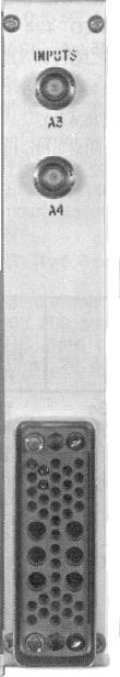
7 1 ORTEC MODEL 533 DUAL SUM AND INVERT AMPLIFIER 1. DESCRIPTION The ORTEC Model 533 Dual Sum and Invert Amplifier is a versatile instrument for general purpose use. It has two inverting operational amplifiers, each of which has multiple inputs to permit summation of signals form separate circuits. By cascading the two amplifier sections, its function becomes a noninverted summation of up to four inputs. Alternatively, each amplifier section may be used to invert its inputs with no crosstalk between the two sections. Amplifier A has four inputs through BNC connectors, two of which are on the front panel and two on the rear panel. Any one input, any combination of inputs, or all four inputs may be used, and the summed and inverted signal is furnished through Output A on the front panel. The gain from each input to the output is unity. The amplifier has a rise of <50 ns, a bandwidth from dc to 7.0 MHZ, and does not include any shaping. The output impedance is <0.1S for line drive and fanout capability. Amplifier B has two inputs, both located on the front panel. Otherwise, the characteristics for this section are identical to those for the Amplifier A section. 2. SPECIFICATIONS 2.1. PERFORMANCE VOLTAGE GAIN Unity for each input; tolerances #±2%. BANDWIDTH dc to 7.0 MHZ (J r #50 ns). INTEGRAL NONLINEARITY <0.05% TEMPERATURE INSTABILITY Gain #±0.005%/ C. Output DC Level <±50 :V/ C INPUTS Four identical inputs for Amplifier A and two for Amplifier B; each accepts 0 to 10 V rated span, 12 V mas, positive or negative, unipolar or bipolar; Z in ~ 666 S, dc-coupled. Inputs A1, A2, B1, and B2 on front panel; Inputs A3 and A4 on rear panel, all BNC connectors OUTPUTS One output on front panel for each Amplifier, A and B, completely independent form each other; range 0 to ± 10 V linear; Z in < 0.1 S; BNC connectors 2.4. ELECTRICAL AND MECHANICAL POWER REQUIREMENTS +12 V, 0 ma; -12 V, 0 ma; +24 V, 65 ma; -24 V, 65 ma. WEIGHT Shipping 2.2 kg (5 lb). Net 0.9 kg (2 lb). DIMENSIONS Standard single-width NIM (1.35 by in.) per TID (Rev). 3. INSTALLATION 3.1. GENERAL The 533, used in conjunction with an ORTEC 4001C/4002A Series Bin and Power Supply, is intended for rack mounting. It is necessary to ensure that the 533 has sufficient cooling air circulating to prevent any localized heating of the all-transistor circuitry used throughout the module. The temperature of equipment mounted in racks can easily exceed the recommended maximum unless precautions are taken. The 533 should not be subjected to temperatures in excess of 120 F (50 C).
8 CONNECTION TO POWER The 533 contains no internal power supply and must therefore obtain power from a Nuclear Standard bin and power supply such as the ORTEC 4001C/4002A. The bin power supply should be turned off when modules are inserted or removed. The ORTEC 4001C/4002A Series is designed so that it is not possible to overload the bin power supply with a full complement of modules in the bin; since, however, this may not be true when the bin contains modules other than those of ORTEC design, the power supply voltage should be checked after the modules are inserted. The ORTEC 4001 C/4002A has test points on the power supply control panel to monitor the dc voltages. When using the 522 outside the 4001C/4002A bin and power supply, be sure that the jumper cable used properly accounts for the power supply grounding circuits set forth in the recommended AEC standards of TID (Rev). Both high-quality and power return ground connections are provided to ensure proper reference feedback into the power supply, and these must be preserved in remote cable installations. Be careful to avoid ground loops when the module is operated outside the bin SIGNAL CONNECTIONS TO THE 533 INPUTS The 533 inputs are compatible with all output signals of the modular electronic instruments. The signal range of the input is from 0 to 10 V. The input range is from dc to pulses as narrow as 100 ns. The 533 characteristics of low noise, dc-coupling, and wide bandwidth make it ideal for following preamplifiers or summing shaping amplifier outputs. The input connector should be determined int eh characteristic impedance of the connecting coaxial cable when cable lengths exceed approximately 5 ft. The input impedance of each input is approximately 1000 S. It is recommended that RG-62/U or RG-63/U coaxial cable be used due to their relatively higher impedances (93 S and 125 S, respectively). If 50 S coaxial cable must be used, be sure that the driving source can drive terminated 50 S cable. Normally, nonlinearity of a system will vary directly with the amount of power being driven; therefore quite often the best method of linearly driving 50 S coaxial cable which needs to be terminated is that of series drive. For example, a series resistance of 50 S is placed between the driving source and the coaxial line for sources whose driving impedance is <2 S. When the line is terminated at the receiving end, the output signal will be divided and only half of it will appear at the receiving end; however, the receiving end may be left open-circuited, and the cable is terminated back at the driving impedance end. In this case, the driven power is very low and the signal is not attenuated LINEAR OUTPUT SIGNAL CONNECTIONS AND TERMINATING IMPEDANCE There are three general methods of termination used. The simplest of these is shunt termination at the receiving end of the cable. A second method is series termination at the sending end. The third is a combination of series and shunt termination, where the cable impedance is matched both in series at the sending end and in shunt at the receiving end. The most effective method is the combination, but terminating by this method reduces the amount of signal strength at the receiving end to 50% of that which is available in the sending instrument. To use shunt termination at the receiving end of the cable, connect the low impedance of the sending device through 93 S cable to the input of the receiving instrument. Then use a BNC tee connector to accept both the interconnecting cable and a 100 S resistive terminator at the input connector of the receiving instrument. Since the input impedance of the receiving instrument is normally 1000 S or more, the effective instrument input impedance with the 100 S terminator will be of the order of 93 S, and this correctly matches the cable. For series termination, use the 93 S output of the sending instrument for the cable connection. Use 93 S cable to interconnect this into the input of the receiving instrument. The 1000 S (or more) normal input impedance at the input connector represents an essentially open circuit, and the series impedance in the sending instrument now provides the proper termination for the cable. For the combination of series and shunt termination, use the 93 S output in the sending instrument for the cable connection and use 93 S cable. At the input for the receiving instrument, use a BNC tee to accept both the interconnecting cable and a 100 S
9 3 resistive terminator. Note that the signal span at the receiving end of this type of receiving circuit will always be reduced to 50% of the signal span furnished by the sending instrument. For your convenience, ORTEC stokes the proper terminators and BNC tees, or you can obtain them from a variety of commercial sources. 4. OPERATING INSTRUCTIONS The 533 is typically used in a linear system following the main pulse shaping amplifier(s). However, it may be used as a summing amplifier prior to pulse shaping in the main amplifier or as a fan-in for logic signals. It has no controls and will simply provide in each output the inverted sum of the related inputs whenever these occur. The connotation of Summing Amplifier is true only when there is a time coincidence of arrival of the input pulses. If the input signals do not arrive in time coincidence, the inputs may be considered a linear fan-in unit. The 533 is directly compatible with and can be driven from any linear or logic signal or it can be used to sum the outputs from preamplifiers, either shaping or nonshaping. Unless the charge conversion gain of each preamplifier is quite high, some degradation in the signal-to-noise ratio may be expected in high resolution systems when summing the preamplifier outputs, since the noise from each unit must be summed in quadrature. 5. MAINTENANCE 5.1. TESTING PERFORMANCE OF THE DUAL SUM AND INVERT AMPLIFIER The following information is intended as an aid in the installation and checkout of the 533. These instructions give information on waveforms at test points and output connectors. TEST EQUIPMENT The following, or equivalent, test equipment is needed: 1. ORTEC 419 or 448 Pulse Generator 2. Tektronix Model 580 Series Oscilloscope S BNC terminators 4. High-impedance dc voltmeter 5. ORTEC 572 Amplifier or equivalent PRELIMINARY PROCEDURES The module should first be checked for possible damage due to shipment. The other preliminary procedures are as follows: 1. Connect ac power to the ORTEC 4001C/4002A Bin and Power Supply. Turn off power. 2. Plug the module into the bin and check for proper mechanical alignment. 3. Switch on the ac power and check the dc-power supply voltages at the test points on the 4002 power supply control panel. AMPLIFIER A AND B There are no internal adjustment to be made to the 533; therefore testing is simply a matter of observation of input and output waveforms as follows: 1. Feed the output of the pulse generator into the input of the 572 Amplifier. 2. Set the amplifier controls as follows: Gain ~5 Time Constants 0.5 or 1 :s 3. Feed the Bipolar Output of the amplifier to the A1 input of the 533 through RG-62/U cable, and terminate the cable at the input of the 533 with a 100 S terminator. 4. Adjust the pulse generator for an output of 500 mv from the The output at Output A of the 533 should be 500 mv and prompt with respect to the input signal. 6. Move the input signal and terminator from the A1 Input, and connect it to the A2 Input. 7. Again, the output should be 500 mv and prompt with respect to the input. Repeat steps 5 and 6 for Inputs A3 and A4. Raise the amplitude of the signal from the amplifier to check the output under high signal conditions. The amplifier should saturate at approximately 11 V. 8. Repeat steps 3 through 7 for Inputs B1 and B2, testing the results at Output B.
10 SUGGESTIONS FOR TROUBLESHOOTING In situations where the 533 is suspected of malfunction, it is essential to verify such malfunction is terms of simple pulse generator pulses at the input and output. The 533 must be disconnected from its position in any system, and routine diagnostic analysis performed with a test pulse generator and an oscilloscope. Testing should not be performed with a source and detector until the Dual Sum and Invert Amplifier performs satisfactorily with the test pulse generator. The testing instruction given in Section 5 should provide assistance in locating and repairing the malfunction. The side plates can be removed completely from the module to permit oscilloscope and voltmeter observation with a minimal chance of accidentally short-circuiting portions of the etched board. Table 5.1 is also presented here as a typical set of dcvoltage measurements against which any unit can be tested FACTORY SERVICE This instrument can be returned to the ORTEC factory for service and repair at a nominal cost. Our standard procedure for repair ensures the same quality control and checkout that are used for a new instrument. Always contact ORTEC Customers Services (865) before sending an instrument for repair to obtain shipping instructions and so that the required Return Authorization Number can be assigned to the unit. Write this number of the address label and on the package to ensure prompt attention when it reaches the ORTEC factory TABULATED TEST POINT VOLTAGES ON ETCHED BOARD Table 5.1 indicates the dc voltages measured on the etched circuit board. In some instances the circuit will perform satisfactorily even though, due to component variations, there may be some voltages that measure outside the given limits; therefore the voltages given here should not be taken as absolute values, but rather are intended to serve as an aid in troubleshooting. Table 5.1 Location Voltage A1 pin ± U1 pin ± A2 pin ± U2 pin ±
11 5 Bin/Module Connector Pin Assignments For Standard Nuclear Instrument Modules per DOE/ER-0457T. Pin Function Pin Function 1 +3 V 23 Reserved 2-3 V 24 Reserved 3 Spare bus 25 Reserved 4 Reserved bus 26 Spare 5 Coaxial 27 Spare 6 Coaxial * V 7 Coaxial *29-24 V V dc 30 Spare bus 9 Spare 31 Spare *10 +6 V 32 Spare *11-6 V * V ac (hot) 12 Reserved bus *34 Power return ground 13 Spare 35 Reset (Scaler) 14 Spare 36 Gate 15 Reserved 37 Reset (Auxiliary) * V 38 Coaxial *17-12 V 39 Coaxial 18 Spare bus 40 Coaxial 19 Reserved bus * V ac (neutral) 20 Spare *42 High-quality ground 21 Spare G Ground guide pin 22 Reserved Pins marked (*) are installed and wired in ORTEC s 4001A and 4001C Modular System Bins.
Model 9302 Amplifier-Discriminator Operating and Service Manual
 Model 9302 Amplifier-Discriminator Operating and Service Manual Printed in U.S.A. ORTEC Part No. 733690 1202 Manual Revision C Advanced Measurement Technology, Inc. a/k/a/ ORTEC, a subsidiary of AMETEK,
Model 427A Delay Amplifier Operating and Service Manual
 Model 427A Delay Amplifier Operating and Service Manual This manual Applies to instruments marked Rev 22" on rear panel Printed in U.S.A. ORTEC Part No. 733210 1202 Manual Revision B Advanced Measurement
Model 863 Quad Timing Filter Amplifier Operating and Service Manual
 Model 863 Quad Timing Filter Amplifier Operating and Service Manual Printed in U.S.A. ORTEC Part No. 733960 0411 Manual Revision C Advanced Measurement Technology, Inc. a/k/a/ ORTEC, a subsidiary of AMETEK,
Model 113 Scintillation Preamplifier Operating and Service Manual
 Model 113 Scintillation Preamplifier Operating and Service Manual Printed in U.S.A. ORTEC Part No. 717560 1202 Manual Revision B Advanced Measurement Technology, Inc. a/k/a/ ORTEC, a subsidiary of AMETEK,
Model 9305 Fast Preamplifier Operating and Service Manual
 Model 9305 Fast Preamplifier Operating and Service Manual This manual applies to instruments marked Rev 03" on rear panel. Printed in U.S.A. ORTEC Part No.605540 1202 Manual Revision B Advanced Measurement
Model 426 Linear Gate Operating and Service Manual
 Model 426 Linear Gate Operating and Service Manual This manual applies to instruments marked Rev 23" on rear panel Printed in U.S.A. ORTEC Part No. 733200 1202 Manual Revision B Advanced Measurement Technology,
Model 416A Gate and Delay Generator Operating and Service Manual
 Model 416A Gate and Delay Generator Operating and Service Manual Printed in U.S.A. ORTEC Part No. 733160 1202 Manual Revision E Advanced Measurement Technology, Inc. a/k/a/ ORTEC, a subsidiary of AMETEK,
Model 428 Detector Bias Supply Operating and Service Manual
 Model 428 Detector Bias Supply Operating and Service Manual Printed in U.S.A. ORTEC Part No. 733220 1202 Manual Revision C Advanced Measurement Technology, Inc. a/k/a/ ORTEC, a subsidiary of AMETEK, Inc.
Model 439 Digital Current Integrator Operating Manual
 Model 439 Digital Current Integrator Operating Manual Printed in U.S.A. ORTEC Part No. 733240 0908 Manual Revision K Advanced Measurement Technology, Inc. a/k/a/ ORTEC, a subsidiary of AMETEK, Inc. WARRANTY
ScintiPack Model 296 Photomultiplier Base with Preamplifier and High Voltage Power Supply Operating and Service Manual
 ScintiPack Model 296 Photomultiplier Base with Preamplifier and High Voltage Power Supply Operating and Service Manual WARNING This equipment generates, uses, and can radiate radio frequency energy, and
Model 449 Log/Lin Ratemeter Operating and Service Manual
 Model 449 Log/Lin Ratemeter Operating and Service Manual Printed in U.S.A. ORTEC Part No. 733270 1202 Manual Revision D Advanced Measurement Technology, Inc. a/k/a/ ORTEC, a subsidiary of AMETEK, Inc.
Model 542 Linear Gate and Stretcher Operating and Service Manual
 Model 542 Linear Gate and Stretcher Operating and Service Manual NOTE: A substitution for the dual diode package (MSD6100) may have been made in this unit. If so, two 1N4153 diodes were used to replace
Model 480 Pulser Operating and Service Manual
 Model 480 Pulser Operating and Service Manual Printed in U.S.A. ORTEC Part No. 733390 1202 Manual Revision B Advanced Measurement Technology, Inc. a/k/a/ ORTEC, a subsidiary of AMETEK, Inc. WARRANTY ORTEC*
Model 9307 pico-timing Discriminator Operating and Service Manual
 Model 9307 pico-timing Discriminator Operating and Service Manual Printed in U.S.A. ORTEC Part No. 764020 1202 Manual Revision C Advanced Measurement Technology, Inc. a/k/a/ ORTEC, a subsidiary of AMETEK,
Model 935 Quad Constant-Fraction 200-MHz Discriminator Operating and Service Manual
 Model 935 Quad Constant-Fraction 200-MHz Discriminator Operating and Service Manual U.S. Patent No. 4,179,644 Printed in U.S.A. ORTEC Part No. 753770 0503 Manual Revision H ii $GYDQFHG0HDVXUHPHQW7HFKQRORJ\,QF
Model 276L Low-Power Photomultiplier Base Operating and Service Manual
 Model 276L Low-Power Photomultiplier Base Operating and Service Manual Printed in U.S.A. ORTEC Part No. 762870 0702 Manual Revision C $GYDQFHG 0HDVXUHPHQW 7HFKQRORJ\,QF a/k/a/ ORTEC, a subsidiary of AMETEK,
Model 566 Time-to-Amplitude Converter (TAC) Operating and Service Manual
 Operating and Service Manual") Model 566 Time-to-Amplitude Converter (TAC) Operating and Service Manual Printed in U.S.A. ORTEC Part No. 678950 0411 Manual Revision F Advanced Measurement Technology, Inc. a/k/a/ ORTEC, a subsidiary
Model 566 Time-to-Amplitude Converter (TAC) Operating and Service Manual Printed in U.S.A. ORTEC Part No. 678950 0411 Manual Revision F Advanced Measurement Technology, Inc. a/k/a/ ORTEC, a subsidiary
Model 142AH Preamplifier Operating and Service Manual
 Model 142AH Preamplifier Operating and Service Manual Printed in U.S.A. ORTEC Part No. 733990 0202 Manual Revision B $GYDQFHG 0HDVXUHPHQW 7HFKQRORJ\,QF a/k/a/ ORTEC, a subsidiary of AMETEK, Inc. WARRANTY
2001A. 200KHz Function Generator Instruction Manual. 99 Washington Street Melrose, MA Phone Toll Free
 2001A 200KHz Function Generator Instruction Manual 99 Washington Street Melrose, MA 02176 Phone 781-665-1400 Toll Free 1-800-517-8431 Visit us at www.testequipmentdepot.com WARRANTY Global Specialties
Model 7000 Low Noise Differential Preamplifier
 Model 7000 Low Noise Differential Preamplifier Operating Manual Service and Warranty Krohn-Hite Instruments are designed and manufactured in accordance with sound engineering practices and should give
P5100A & P5150 High Voltage Probes Performance Verification and Adjustments
 x P5100A & P5150 High Voltage Probes Performance Verification and Adjustments ZZZ Technical Reference *P077053001* 077-0530-01 xx P5100A & P5150 High Voltage Probes Performance Verification and Adjustments
INSTRUCTION MANUAL. March 11, 2003, Revision 3
 INSTRUCTION MANUAL Model 701A Stimulator March 11, 2003, Revision 3 Copyright 2003 Aurora Scientific Inc. Aurora Scientific Inc. 360 Industrial Parkway S., Unit 4 Aurora, Ontario, Canada L4G 3V7 Tel: 1-905-727-5161
Model 460 Delay Line Amplifier Operating and Service Manual
 Model 460 Delay Line Amplifier Operating and Service Manual Printed in U.S.A. ORTEC Part No. 733320 1202 Manual Revision C Advanced Measurement Technology, Inc. a/k/a/ ORTEC, a subsidiary of AMETEK, Inc.
PCO-7114 Laser Diode Driver Module Operation Manual
 PCO-7114 Laser Diode Driver Module Operation Manual Directed Energy, Inc. 1609 Oakridge Dr., Suite 100, Fort Collins, CO 80525, (970) 493-1901 sales@ixyscolorado.com www.ixyscolorado.com Manual Document
VT1586A Rack Mount Terminal Panel Installation and User s Manual
 VT1586A Rack Mount Terminal Panel Installation and User s Manual Manual Part Number: 82-0095-000 Rev. June 16, 2003 Printed in U.S.A. Certification VXI Technology, Inc. certifies that this product met
Broadband Power Amplifier
 601L Broadband Power Amplifier HIGH RF VOLTAGES MAY BE PRESENT AT THE OUTPUT OF THIS UNIT. All operating personnel should use extreme caution in handling these voltages and be thoroughly familiar with
BC145 SIGNAL ISOLATOR BOARD
 BC145 SIGNAL ISOLATOR BOARD 4/17 Installation & Operating Manual MN1373 Any trademarks used in this manual are the property of their respective owners. Important: Be sure to check www.baldor.com to download
Model 855 Dual Spectroscopy Amplifier Operating and Service Manual
 Model 855 Dual Spectroscopy Amplifier Operating and Service Manual This manual applies to instruments marked Rev. 03" on rear panel. Printed in U.S.A. ORTEC Part No. 717490 0406 Manual Revision C $GYDQFHG0HDVXUHPHQW7HFKQRORJ\,QF
2015 RIGOL TECHNOLOGIES, INC.
 Service Guide DG000 Series Dual-channel Function/Arbitrary Waveform Generator Oct. 205 TECHNOLOGIES, INC. Guaranty and Declaration Copyright 203 TECHNOLOGIES, INC. All Rights Reserved. Trademark Information
201AP Charge Amplifier User Manual
 Trig-Tek 201AP Charge Amplifier User Manual Publication No. 980996 Rev. A Astronics Test Systems Inc. 4 Goodyear, Irvine, CA 92618 Tel: (800) 722-2528, (949) 859-8999; Fax: (949) 859-7139 atsinfo@astronics.com
Model 673 Spectroscopy Amplifier and Gated Integrator Operating and Service Manual
 Model 673 Spectroscopy Amplifier and Gated Integrator Operating and Service Manual Printed in U.S.A. ORTEC Part No. 675590 0202 Manual Revision B $GYDQFHG 0HDVXUHPHQW 7HFKQRORJ\,QF a/k/a/ ORTEC, a subsidiary
Broadband Step-Up Transformer. User Manual
 Broadband Step-Up Transformer User Manual 990-1930 09/2004 Introduction Introduction About this unit The APC Step-Up Transformer provides 220 V power from 60 VAC Broadband cable systems. Safety Electrical
Model 5100F. Advanced Test Equipment Rentals ATEC (2832) OWNER S MANUAL RF POWER AMPLIFIER
 OWNER S MANUAL RF POWER AMPLIFIER") Established 1981 Advanced Test Equipment Rentals www.atecorp.com 800-404-ATEC (2832) OWNER S MANUAL Model 5100F RF POWER AMPLIFIER 0.8 2.5 GHz, 25 Watts Ophir RF 5300 Beethoven Street Los Angeles, CA 90066
Established 1981 Advanced Test Equipment Rentals www.atecorp.com 800-404-ATEC (2832) OWNER S MANUAL Model 5100F RF POWER AMPLIFIER 0.8 2.5 GHz, 25 Watts Ophir RF 5300 Beethoven Street Los Angeles, CA 90066
Directed Energy, Inc Oakridge Dr., Suite 100, Fort Collins, CO
 PCO-7121 Laser Diode Driver Module Operation Manual Directed Energy, Inc. 1609 Oakridge Dr., Suite 100, Fort Collins, CO 80525 sales@ixyscolorado.com www.ixyscolorado.com Contents Contents... 3 Safety...
Model 8140VT VERSATAP INSTALLATION AND OPERATION MANUAL
 VERSATAP INSTALLATION AND OPERATION MANUAL 95 Methodist Hill Drive Rochester, NY 14623 Phone: US +1.585.321.5800 Fax: US +1.585.321.5219 www.spectracomcorp.com Part Number 8147-5000-0050 Manual Revision
Model 1791 VHF Radio User's Manual
 Model 79 VHF Radio User's Manual ALL WEATHER INC 65 NATIONAL DRIVE SACRAMENTO, CA 95834 WWW.ALWEATHERINC.COM 79 VHF RADIO USER'S MANUAL CONTENTS INTRODUCTION... Description... Transmitter Module... Power
BROADBAND'LINEAR'AMPLIFIER WITH'A±B'INPUTS'AND'DC5OFFSET Model&A400X
 ELECTRONICS AB BROADBAND'LINEAR'AMPLIFIER WITH'A±B'INPUTS'AND'DC5OFFSET ModelA400X HIGHVOLTAGE FIXEDGAIN BROADBAND ±200V 150mA 20x DCtoca500kHz FULLSCALE LOWOUTPUTIMPEDANCE HIGHSLEWRATE
P5100A & P5150 High Voltage Probes Performance Verification and Adjustments
 x P5100A & P5150 High Voltage Probes Performance Verification and Adjustments ZZZ Technical Reference *P077053002* 077-0530-02 xx P5100A & P5150 High Voltage Probes Performance Verification and Adjustments
DUAL CHANNEL BROADBAND LINEAR AMPLIFIER Model A800D
 DUAL CHANNEL BROADBAND LINEAR AMPLIFIER Model A800D HIGH VOLTAGE FIXED GAIN BROADBAND 800Vpp 60mA 100x DC to ca 200 khz LOW OUTPUT IMPEDANCE HIGH SLEW RATE
Distribution Amplifiers 1
 Distribution Amplifiers 1-30dB PUT 49-750 MHz 43 db GA POWER DOUBLED P/N: 1002705 REVERSE GA M MAX DESCRIPTION The R.L. DRAKE models DA8642, DA8632,, and DA7533, are broadband distribution amplifiers designed
TRANSDUCER IN-LINE AMPLIFIER
 TRANSDUCER IN-LINE Voltage Model AMPLIFIER 2080 Arlingate, Columbus, Ohio 43228, (614) 850-5000 Sensotec, Inc. 2080 Arlingate Lane Columbus, Ohio 43228 Copyright 1995 by Sensotec, Inc. all rights reserved
ADA416-XLR DISTRIBUTION AMPLIFIERS OPERATING AND MAINTENANCE MANUAL
 ADA416-XLR DISTRIBUTION AMPLIFIERS OPERATING AND MAINTENANCE MANUAL Copyright 2015, ATI Audio Inc. DESCRIPTION Your ADA416-XLR provides four independent one-in by four-out circuit groups. A four-output
User Manual. Smart-UPS On-Line. Uninterruptible Power Supply. Isolation Transformer Models: SURT001 and SURT002
 User Manual Smart-UPS On-Line Uninterruptible Power Supply Isolation Transformer Models: SURT001 and SURT002 Isolation and Step-Down Transformer Models: SURT003 and SURT004 General Information Important
PARALLEL MULTI-AMP KIT for 7200 Series AMPLIFIERS INSTRUCTION SHEET
 2 5 0 7 W a r r e n S t r e e t, E l k h a r t, I N 4 6 5 1 6 U S A 5 7 4. 2 9 5. 9 4 9 5 w w w. A E T e c h r o n. c o m PARALLEL MULTI-AMP KIT for 7200 Series AMPLIFIERS INSTRUCTION SHEET Kit Contents:
305 Stimulus Isolator. Description
 Description The Model 305 Stimulus Isolator utilizes photon coupling to provide nearly ideal isolation of the pulse and train outputs of the WPI Series 300 Anapulse Stimulators. Two Model 305 units are
RIGOL. User s Guide. RP5600 Passive Probe. July 2010 RIGOL Technologies, Inc.
 User s Guide RP5600 Passive Probe July 2010 RIGOL Technologies, Inc. Guaranty and Declaration Copyright 2010 RIGOL Technologies, Inc. All Rights Reserved. Trademark Information RIGOL is a registered trademark
Operator s Manual. PP016 Passive Probe
 Operator s Manual PP016 Passive Probe 2017 Teledyne LeCroy, Inc. All rights reserved. Unauthorized duplication of Teledyne LeCroy documentation materials is strictly prohibited. Customers are permitted
Glass Electrode Meter
 Glass Electrode Meter INSTRUCTION MANUAL FOR Glass Electrode R/C Meter MODEL 2700 Serial # Date PO Box 850 Carlsborg, WA 98324 U.S.A. 360-683-8300 800-426-1306 FAX: 360-683-3525 http://www.a-msystems.com
AMP-13 OPERATOR S MANUAL
 AMP-13 OPERATOR S MANUAL Version 2.0 Copyright 2008 by Vatell Corporation Vatell Corporation P.O. Box 66 Christiansburg, VA 24068 Phone: (540) 961-3576 Fax: (540) 953-3010 WARNING: Read instructions carefully
PDB4. Four Channel Passive Direct Box USER'S GUIDE
 PDB4 Four Channel Passive Direct Box USER'S GUIDE IMPORTANT SAFETY INSTRUCTIONS - READ FIRST This symbol, wherever it appears, alerts you to important operating and maintenance instructions in the accompanying
HP 86290B RF PLUG-IN GHz HEWLETT PACKARD
 OPERATING AND SERVICE MANUAL. HP 86290B RF PLUG-IN 2.0-18.6 GHz HEWLETT PACKARD COPYRIGHT AND DISCLAIMER NOTICE Copyright - Agilent Technologies, Inc. Reproduced with the permission of Agilent Technologies
DUAL%CHANNEL%LINEAR%AMPLIFIER %WITH%PHASE%INVERTER Model&A400DI
 ELECTRONICS AB DUAL%CHANNEL%LINEAR%AMPLIFIER %WITH%PHASE%INVERTER ModelA400DI HIGHVOLTAGE FIXEDGAIN BROADBAND ±200V 150mA 20x DCtoca500kHz FULLSCALE LOWOUTPUTIMPEDANCE HIGHSLEWRATE
SUBNANOSECOND PULSE GENERATOR PPG-2/1000 USER MANUAL
 SUBNANOSECOND PULSE GENERATOR PPG-2/1000 USER MANUAL 2015 Megaimpulse Ltd. Copyright 2015 MEGAIMPULSE Ltd. All Rights Reserved. MEGAIMPULSE LTD. PROVIDES THIS MANUAL "AS IS" WITHOUT WARRANTY OF ANY KIND,
TA MHz oscilloscope probe TA MHz oscilloscope probe
 TA375 100 MHz oscilloscope probe TA386 200 MHz oscilloscope probe User's Guide X1 X10 TA386 X1/X10 Max. 600 Vp Introduction This passive high-impedance oscilloscope probe is suitable for most oscilloscopes
DA208 & DA416 DISTRIBUTION AMPLIFIERS OPERATING AND MAINTENANCE MANUAL
 DA208 & DA416 DISTRIBUTION AMPLIFIERS OPERATING AND MAINTENANCE MANUAL Copyright 2011, ATI Audio Inc. DESCRIPTION Your DA208 or DA416 provides two (DA208) or four (DA416) independent one-in by four-out
RIGOL. User s Guide. RP1000D Series High Voltage Differential Probe. Feb RIGOL Technologies, Inc
 User s Guide RP1000D Series High Voltage Differential Probe Feb. 2013 RIGOL Technologies, Inc Guaranty and Declaration Copyright 2012 RIGOL Technologies, Inc. All Rights Reserved. Trademark Information
ELECTROSURGICAL UNIT ANALYZER
 ELECTROSURGICAL UNIT ANALYZER ESU-2000A USER MANUAL BC BIOMEDICAL ESU-2000A TABLE OF CONTENTS WARNINGS, CAUTIONS, NOTICES... ii DESCRIPTION... 1 OVERVIEW... 2 OPERATING INSTRUCTIONS... 3 MANUAL REVISIONS...
411LA Broadband Power Amplifier
 411LA Broadband Power Amplifier HIGH RF VOLTAGES MAY BE PRESENT AT THE OUTPUT OF THIS UNIT. All operating personnel should use extreme caution in handling these voltages and be thoroughly familiar with
High Performance Microphone Splitter. Artcessories. User's Manual
 High Performance Microphone Splitter Artcessories User's Manual IMPORTANT SAFETY INSTRUCTION READ FIRST This symbol, whenever it appears, alerts you to the presence of uninsulated dangerous voltage inside
Model Hz to 10MHz Precision Phasemeter. Operating Manual
 Model 6610 1Hz to 10MHz Precision Phasemeter Operating Manual Service and Warranty Krohn-Hite Instruments are designed and manufactured in accordance with sound engineering practices and should give long
CLEANING CALIBRATION INTERVAL
 &DUHDQG0DLQWHQDQFH! &DUHDQG0DLQWHQDQFH CLEANING CALIBRATION INTERVAL SERVICE STRATEGY TROUBLESHOOTING A. Trace Off Scale The exterior of the probe and cable should be cleaned only using a soft cloth moistened
User s Guide RIGOL. PA1000 Series Power Amplifier. Publication number: UGF Mar RIGOL TECHNOLOGIES, INC. All Rights Reserved.
 User s Guide Publication number: UGF01103-1110 Mar. 2017 PA1000 Series Power Amplifier 2009 TECHNOLOGIES, INC. All Rights Reserved. Copyright Information 2009 TECHNOLOGIES, INC. All Rights Reserved. products
CURRENT MEARUREMENT SHUNT CS-10/500 USER MANUAL
 CURRENT MEARUREMENT SHUNT CS-10/500 USER MANUAL 2017 Megaimpulse Ltd. Copyright 2017 MEGAIMPULSE Ltd. All Rights Reserved. MEGAIMPULSE LTD. PROVIDES THIS MANUAL "AS IS" WITHOUT WARRANTY OF ANY KIND, EITHER
Radio Remote Controls Manual K Series
 Radio Remote Controls Manual K Series PN 52764 2010.12.20 Rev. 2 K Series radio control manual 1 Conductix Incorporated The technical data and images which appear in this manual are for informational purposes
Current Probes. User Manual
 Current Probes User Manual ETS-Lindgren Inc. reserves the right to make changes to any product described herein in order to improve function, design, or for any other reason. Nothing contained herein shall
200B Clipper Module User Manual
 Trig-Tek 200B Clipper Module User Manual Publication No. 980954 Rev. A Astronics Test Systems Inc. 4 Goodyear, Irvine, CA 92618 Tel: (800) 722-2528, (949) 859-8999; Fax: (949) 859-7139 atsinfo@astronics.com
Log Periodic Antenna
 Page 1 of 10 Log Periodic Antenna ALFM 80120 88 MHz to 108 MHz (Extendible to 80 to 120 MHz) Page 2 of 10 Table of Contents 1.0 Introduction... 3 2.0 Product Specifications... 4 3.0 Important Safety Precautions...
OPERATION & SERVICE MANUAL FOR FC 110 AC POWER SOURCE
 OPERATION & SERVICE MANUAL FOR FC 100 SERIES AC POWER SOURCE FC 110 AC POWER SOURCE VERSION 1.3, April 2001. copyright reserved. DWG No. FC00001 TABLE OF CONTENTS CHAPTER 1 INTRODUCTION... 1 1.1 GENERAL...
BROADBAND'LINEAR'AMPLIFIER Model&F10AD
 BROADBAND'LINEAR'AMPLIFIER Model&F10AD DUAL'CHANNEL & HIGH&VOLTAGE& FIXED&GAIN& BROADBAND & ±100V&185mA& 10x& DC&to&ca&1&MHz & HIGH&SLEW&RATE& LOW&OUTPUT&IMPEDANCE & 400&V/µs&
DL102 Counter Loop Amplifier
 DL102 Counter Loop Amplifier USER MANUAL MAN 234A Contents Overview...3 System Includes...3 Maintenance and Recycling Instructions...3 Safety Information...4 Quick Setup...5 Setup...6 Loop Amplifier...6
Advanced Test Equipment Rentals ATEC (2832)
") Established 1981 Advanced Test Equipment Rentals www.atecorp.com 800-404-ATEC (2832) A.H. Systems Model Active Monopole Antennas Active Monopole Antenna Series Operation Manual 1 TABLE OF CONTENTS INTRODUCTION
Established 1981 Advanced Test Equipment Rentals www.atecorp.com 800-404-ATEC (2832) A.H. Systems Model Active Monopole Antennas Active Monopole Antenna Series Operation Manual 1 TABLE OF CONTENTS INTRODUCTION
TETRIS User's Guide. High Impedance Active Probe DO177-1
 TETRIS 1500 High Impedance Active Probe User's Guide DO177-1 TETRIS 1500 Copyright 2010 Ltd. All rights reserved. Information in this publication supersedes that in all previously published material. Specifications
BROADBAND LINEAR AMPLIFIER Model P150
 ELECTRONICS AB BROADBAND LINEAR AMPLIFIER Model P150 HIGH VOLTAGE GAIN HIGH CURRENT +150V 20x 1A HIGH POWER SMALL SIGNAL SLEW RATE BANDWIDTH BANDWIDTH 30 V/µs DC to ca 60 khz DC to >200 khz FLC Electronics
Model MV106J/MV116J. ±10nVdc to ±11Vdc Precision DC Voltage Standard Source. Operating Manual
 Model MV106J/MV116J ±10nVdc to ±11Vdc Precision DC Voltage Standard Source Operating Manual This page intentionally left blank. MV 106 & MV116 OPERATORS MANUAL Serial No. Win-man\mvman.wpd This page intentionally
User Instructions. Model PS-2001L. Power Supply. Model SPS Power Supply. Audiocom Intercom Systems Rev. A, 4/2001.
 User Instructions PS-00L Model PS-00L Power Supply SPS-00 Volume Model SPS-00 Power Supply Audiocom Intercom Systems 950-7699-000 Rev. A, /00 FCC Statement This equipment uses, and can radiate radio frequency
SX204. Headphone Amplifier. Symetrix. Owner s Manual
 Symetrix SX204 Headphone Amplifier Owner s Manual Symetrix Inc. 14926 35th Avenue West Lynnwood, Washington 98037 Voice: (206) 787-3222, (800) 288-8855 Fax: (206) 787-3211 Copyright 1988, 1994 Symetrix
MaxLite Linear Strip ECO Series
 General Safety Information To reduce the risk of death, personal injury or property damage from fire, electric shock, falling parts, cuts/abrasions, and other hazards read all warnings and instructions
KRAMER ELECTRONICS LTD. USER MANUAL MODEL: 912 Power Amplifier. P/N: Rev 2
 KRAMER ELECTRONICS LTD. USER MANUAL MODEL: 912 Power Amplifier P/N: 2900-000684 Rev 2 Contents 1 Introduction 1 2 Getting Started 2 2.1 Achieving the Best Performance 2 3 Overview 3 3.1 Defining the 912
DC200A Displacement Clipper User Manual
 Trig-Tek DC200A Displacement Clipper User Manual Publication No. 980981 A Inc. 4 Goodyear, Irvine, CA 92618 Tel: (800) 722-2528, (949) 859-8999; Fax: (949) 859-7139 atsinfo@astronics.com atssales@astronics.com
INSTALLATION AND MAINTENANCE MANUAL FOR GROUND MONITOR GM-250 COPYRIGHT 1983 AMERICAN MINE RESEARCH, INC.
 INSTALLATION AND MAINTENANCE MANUAL FOR GROUND MONITOR GM-250 COPYRIGHT 1983 AMERICAN MINE RESEARCH, INC. MANUAL PART NUMBER 180-0036 ORIGINAL: 1-17-83 REVISION: B (8-26-86) NOT TO BE CHANGED WITHOUT MSHA
TRANSDUCER IN-LINE AMPLIFIER
 TRANSDUCER IN-LINE Bi-Polar Model AMPLIFIER 2080 Arlingate Lane, Columbus, Ohio 43228 (614) 850-5000 Sensotec, Inc. 2080 Arlingate Lane Columbus, Ohio 43228 Copyright 1995 by Sensotec, Inc. all rights
80i-600A AC Current Probe
 x Instruction Sheet 80i-600A AC Current Probe INTRODUCTION The Model 80i-600A is a clamp-on ac current probe designed to extend the current measuring capability of an ac current meter to 600 amperes. A
CIRCUIT-TEST ELECTRONICS
 USER'S MANUAL Sweep Function Generator with Counter SWF-8030 CIRCUIT-TEST ELECTRONICS www.circuittest.com TABLE OF CONTENTS SAFETY INFORMATION...page 3 INTRODUCTION... 4 SPECIFICATIONS... 5 FRONT PANEL
HTA125A/250A. Power Amplifiers. Installation & Use Manual
 HTA125A/250A Power Amplifiers Installation & Use Manual Specifications subject to change without notice. 2010 Bogen Communications, Inc. All rights reserved. 54-5832-04B 1011 NOTICE: Every effort was made
Radio Remote(s) (Installation Manual)
 (Installation Manual)") Radio Remote(s) (Installation Manual) 87 Progress Avenue, Tyngsboro, MA 01879, USA Phone (978) 649-4ECU Fax (978) 649-8363 http://www.qtiusa.com Trademarks, Version, Printing, and Copyright Trademarks
Radio Remote(s) (Installation Manual) 87 Progress Avenue, Tyngsboro, MA 01879, USA Phone (978) 649-4ECU Fax (978) 649-8363 http://www.qtiusa.com Trademarks, Version, Printing, and Copyright Trademarks
34134A AC/DC DMM Current Probe. User s Guide. Publication number April 2009
 User s Guide Publication number 34134-90001 April 2009 For Safety information, Warranties, Regulatory information, and publishing information, see the pages at the back of this book. Copyright Agilent
SI-125 Power Amplifier Manual 6205 Kestrel Road; Mississauga, Ontario; Canada; L5T 2A1 November 2016, Rev 0.5
 SI-125 Power Amplifier Manual 6205 Kestrel Road; Mississauga, Ontario; Canada; L5T 2A1 November 2016, Rev 0.5 Phone: (905) 564-0801 Fax: (905) 564-0806 www.telecor.com E:\T2-108\T2-M108-ABC\T2-M108-B.doc/AD
Owner s Manual & Safety Instructions
 Owner s Manual & Safety Instructions Save This Manual Keep this manual for the safety warnings and precautions, assembly, operating, inspection, maintenance and cleaning procedures. Write the product s
CBA 400M MHZ to 400 MHZ
 1 CBA 400M-100 1 MHZ to 400 MHZ 100 watt amplifier user Manual 601-298A CBA 400M-100 1 MHZ to 400 MHZ 100 watt amplifier USER Manual CBA 400M-100 User Manual contents 1 Safety information 5 2 Introduction
BROADBAND LINEAR AMPLIFIER Model F1020 (models F10A and F20A combined)
") BROADBAND LINEAR AMPLIFIER Model F1020 (models F10A and F20A combined) HIGH VOLTAGE FIXED GAIN BROADBAND ±100V 185mA/±150V 150mA 10x/20x DC to ca 1 MHz HIGH SLEW RATE LOW OUTPUT IMPEDANCE 300 V/µs
BROADBAND LINEAR AMPLIFIER Model F1020 (models F10A and F20A combined) HIGH VOLTAGE FIXED GAIN BROADBAND ±100V 185mA/±150V 150mA 10x/20x DC to ca 1 MHz HIGH SLEW RATE LOW OUTPUT IMPEDANCE 300 V/µs
DYNAMIC ENGINEERING 435 Park Dr., Ben Lomond, Calif Fax Est.
 DYNAMIC ENGINEERING 435 Park Dr., Ben Lomond, Calif. 95005 831-336-8891 Fax 831-336-3840 http://www.dyneng.com sales@dyneng.com Est. 1988 User Manual PIM-Parallel-IO PMC IO Module for PMC Parallel IO PIM
Current Probe Fixture Instruction Manual
 Current Probe Fixture Instruction Manual 1 TABLE OF CONTENTS INTRODUCTION 3 GENERAL INFORMATION 4 TEST METHODS 5 SAFETY 7 FIGURES 8 FORMULAS 10 MAINTENANCE 11 WARRANTY 12 2 INTRODUCTION figure 1 Mechanical
TETRIS 1000 High Impedance Active Probe. Instruction Manual
 TETRIS 1000 High Impedance Active Probe Instruction Manual Copyright 2015 PMK GmbH All rights reserved. Information in this publication supersedes that in all previously published material. Specifications
41P Portable Calibrator User Manual
 Trig-Tek 41P Portable Calibrator User Manual Publication No. 980961 Rev. A Astronics Test Systems Inc. 4 Goodyear, Irvine, CA 92618 Tel: (800) 722-2528, (949) 859-8999; Fax: (949) 859-7139 atsinfo@astronics.com
Questions? Call Toll-Free
 List Instruction Manual & Parts IMPORTANT! PLEASE READ INSTRUCTIONS CAREFULLY Failure to install and operate MAC products according to our specified instructions could result in equipment malfunction or
Model 34A. 3Hz to 2MHz 2-Channel Butterworth/Bessel HP, LP, BP, BR Plug-In Filter Card for Model 3905/3916 Chassis.
 Model 34A 3Hz to 2MHz 2-Channel Butterworth/Bessel HP, LP, BP, BR Plug-In Filter Card for Model 3905/3916 Chassis Operating Manual Service and Warranty Krohn-Hite Instruments are designed and manufactured
XPR522 XPR540. XPR SERIES INSTALLATION / OWNER'S MANUAL Mobile Power Amplifiers
 XPR522 XPR540 XPR SERIES INSTALLATION / OWNER'S MANUAL Mobile Power Amplifiers Preparation Please read entire manual before installation. Due to the technical nature of amplifiers, it is highly recommended
INSTALLATION GUIDE. Video Balun Transceiver with fixed BNC for twisted pair operation with other balun transceivers or active receivers.
 INSTALLATION GUIDE VB37M Video Balun Transceiver for Twisted Pair Description Video Balun Transceiver with fixed BNC for twisted pair operation with other balun transceivers or active receivers. The VB37M
Keysight N2771B 30 kv High Voltage Probe
 Keysight N2771B 30 kv High Voltage Probe User s Guide Notices Keysight Technologies, Inc. 2012-2015 No part of this manual may be reproduced in any form or by any means (including electronic storage and
User s Guide. RP7000 Series Active Probe. Dec RIGOL Technologies, Inc.
 User s Guide RP7000 Series Active Probe Dec. 2012 RIGOL Technologies, Inc. Guaranty and Declaration Copyright 2011 RIGOL Technologies, Inc. All Rights Reserved. Trademark Information RIGOL is a registered