Model 449 Log/Lin Ratemeter Operating and Service Manual
|
|
|
- Linda McCormick
- 5 years ago
- Views:
Transcription
1 Model 449 Log/Lin Ratemeter Operating and Service Manual Printed in U.S.A. ORTEC Part No Manual Revision D
2 Advanced Measurement Technology, Inc. a/k/a/ ORTEC, a subsidiary of AMETEK, Inc. WARRANTY ORTEC* warrants that the items will be delivered free from defects in material or workmanship. ORTEC makes no other warranties, express or implied, and specifically NO WARRANTY OF MERCHANTABILITY OR FITNESS FOR A PARTICULAR PURPOSE. ORTEC s exclusive liability is limited to repairing or replacing at ORTEC s option, items found by ORTEC to be defective in workmanship or materials within one year from the date of delivery. ORTEC s liability on any claim of any kind, including negligence, loss, or damages arising out of, connected with, or from the performance or breach thereof, or from the manufacture, sale, delivery, resale, repair, or use of any item or services covered by this agreement or purchase order, shall in no case exceed the price allocable to the item or service furnished or any part thereof that gives rise to the claim. In the event ORTEC fails to manufacture or deliver items called for in this agreement or purchase order, ORTEC s exclusive liability and buyer s exclusive remedy shall be release of the buyer from the obligation to pay the purchase price. In no event shall ORTEC be liable for special or consequential damages. Quality Control Before being approved for shipment, each ORTEC instrument must pass a stringent set of quality control tests designed to expose any flaws in materials or workmanship. Permanent records of these tests are maintained for use in warranty repair and as a source of statistical information for design improvements. Repair Service If it becomes necessary to return this instrument for repair, it is essential that Customer Services be contacted in advance of its return so that a Return Authorization Number can be assigned to the unit. Also, ORTEC must be informed, either in writing, by telephone [(865) ] or by facsimile transmission [(865) ], of the nature of the fault of the instrument being returned and of the model, serial, and revision ("Rev" on rear panel) numbers. Failure to do so may cause unnecessary delays in getting the unit repaired. The ORTEC standard procedure requires that instruments returned for repair pass the same quality control tests that are used for new-production instruments. Instruments that are returned should be packed so that they will withstand normal transit handling and must be shipped PREPAID via Air Parcel Post or United Parcel Service to the designated ORTEC repair center. The address label and the package should include the Return Authorization Number assigned. Instruments being returned that are damaged in transit due to inadequate packing will be repaired at the sender's expense, and it will be the sender's responsibility to make claim with the shipper. Instruments not in warranty should follow the same procedure and ORTEC will provide a quotation. Damage in Transit Shipments should be examined immediately upon receipt for evidence of external or concealed damage. The carrier making delivery should be notified immediately of any such damage, since the carrier is normally liable for damage in shipment. Packing materials, waybills, and other such documentation should be preserved in order to establish claims. After such notification to the carrier, please notify ORTEC of the circumstances so that assistance can be provided in making damage claims and in providing replacement equipment, if necessary. Copyright 2002, Advanced Measurement Technology, Inc. All rights reserved. *ORTEC is a registered trademark of Advanced Measurement Technology, Inc. All other trademarks used herein are the property of their respective owners.
3 iii CONTENTS WARRANTY... ii SAFETY INSTRUCTIONS AND SYMBOLS... iv SAFETY WARNINGS AND CLEANING INSTRUCTIONS... v 1. DESCRIPTION GENERAL DATA AVAILABILITY OPTIONAL AUDIBLE OUTPUT SPECIFICATIONS INSTALLATION GENERAL CONNECTION TO POWER INPUT CONNECTION RECORDER CONNECTION ANALOG 10-V OUTPUT OPERATING INSTRUCTIONS CONTROL PANEL FUNCTIONS THEORY OF OPERATION LINEAR OPERATION ACCURACY OF LINEAR RANGES LOGARITHMIC OPERATION ACCURACY OF LOGARITHMIC RANGE RESPONSE TO AN INPUT RATE CHANGE OPTIONAL AUDIBLE OUTPUT CALIBRATION EQUIPMENT REQUIRED MEASUREMENT OF TEST POINT VOLTAGES OUTPUT ZERO LEVEL RANGE CALIBRATION TROUBLESHOOTING FACTORY REPAIR... 10
4 iv SAFETY INSTRUCTIONS AND SYMBOLS This manual contains up to three levels of safety instructions that must be observed in order to avoid personal injury and/or damage to equipment or other property. These are: DANGER WARNING CAUTION Indicates a hazard that could result in death or serious bodily harm if the safety instruction is not observed. Indicates a hazard that could result in bodily harm if the safety instruction is not observed. Indicates a hazard that could result in property damage if the safety instruction is not observed. Please read all safety instructions carefully and make sure you understand them fully before attempting to use this product. In addition, the following symbol may appear on the product: ATTENTION Refer to Manual DANGER High Voltage Please read all safety instructions carefully and make sure you understand them fully before attempting to use this product.
5 v SAFETY WARNINGS AND CLEANING INSTRUCTIONS DANGER Opening the cover of this instrument is likely to expose dangerous voltages. Disconnect the instrument from all voltage sources while it is being opened. WARNING Using this instrument in a manner not specified by the manufacturer may impair the protection provided by the instrument. Cleaning Instructions To clean the instrument exterior:! Unplug the instrument from the ac power supply.! Remove loose dust on the outside of the instrument with a lint-free cloth.! Remove remaining dirt with a lint-free cloth dampened in a general-purpose detergent and water solution. Do not use abrasive cleaners. CAUTION To prevent moisture inside of the instrument during external cleaning, use only enough liquid to dampen the cloth or applicator.! Allow the instrument to dry completely before reconnecting it to the power source.
6 vi
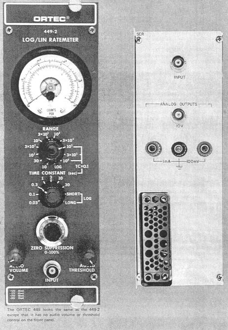
7 1 ORTEC MODEL 449 LOG/LIN RATEMETER WITH OPTIONAL AUDIBLE OUTPUT 1. DESCRIPTION 1.1. GENERAL The ORTEC Model 449 is a double-width NIMstandard modular ratemeter that measures the average count rate of input pulses. The measurements are based on a selected full-scale rate, with a wide range of selections for linear indications and for logarithmic indications. When the input pulse rate is fairly constant, a linear range can be selected that will accommodate the rate, whether it is low, medium, or high. When the input pulse rate varies through a wide range, the logarithmic scale will expand the range for better interpretation of changes when the rate is low and will still accommodate the high count rates within the same total range. There are 11 linear ranges with full-scale values of 10 counts/sec through 10 6 counts/sec. The range of the log scale is 10 through 10 6 counts/sec in 5 decades. A variety of time constants can be selected. Each selection determines the relative averaging capacity for measurements of varying counting rates and also the time interval after a sudden rate change until the indication reaches an equilibrium. The proper selection is a function of the average counting rate, the selected range, and the purpose for which the measurement is made (to measure a true average rate or to identify rate changes quickly) DATA AVAILABILITY Any measured counting rate will be shown on the front-panel meter with a 240 full-scale deflection for accurate readability. It is also available through rear-panel connectors as a proportional analog value of voltage or current. The outputs on the rear panel can be used to drive a recorder, an external indicating meter, an oscilloscope, and/or a device such as the ORTEC 461 Alarm Control. The full-scale range of the current output is 0 to 1 ma. This is intended for an input to a current-type recorder that is adjusted for 1 ma full scale. The full -scale range of the comparable voltage output is 0 to 100 mv, intended for use as the input to a voltage-type recorder that is adjusted for 10 mv full scale. Both outputs are furnished through binding posts that are appropriate for the recorder interconnections. The full-scale range of the analog output through the rear-panel BNC connector is 0 to 10V, which is furnished through an output impendance of 100S. For any measurement the proportional meter deflection and the proportion of the analog full-scale of the analog full-scale values will always be equal. For example, when the meter reads 50% of full scale, the three analog outputs will be 500 :A, 500 :V, and 5 V respectively OPTIONAL AUDIBLE OUTPUT The optional audible output is identified as the ORTEC When it is included, the frequency of the sound from the speaker will be a tone in the range 0 through 500 Hz. The actual frequency will be proportional to the relative meter deflection. There are tow controls for the audible output: a volume control and a threshold adjustment. The threshold can be advanced to eliminate all sound output until the counting rate exceeds a selected level; from the threshold up to the full-scale range, the audio frequency will be proportional to the meter deflection, as it would have been with no suppression.
8 2 2. SPECIFICATIONS PERFORMANCE LINEAR 11 RANGES FROM 10 1 TO 10 6 COUNTS/SEC FULL SCALE IN STEPS. Dead Time #0.3% of the average pulse spacing for ranges from 10 1 through 3 x 10 4 counts/sec; #1% on 10 5 range; #3% on 3 x 10 5 range; and #10% on 10 6 range. Rate Overload Maintains full-scale output for X300 overload to a limit of 10 7 counts/sec. Temperature Stability #+0.05%/ C, 0 to 50 C. Analog Output Nonlinearity #+0.15% of full scale for ranges from 10 1 through 3 x 10 4 counts/sec; #+2% of full scale for ranges from 10 5 through 10 6 counts/sec. Meter accuracy #+2% of full scale. LOGARITHMIC One 5-decade range from 10 1 to Temperature Stability #+0.25% of full scale per C, 0 to 50 C. Analog Output #+2.5% of full scale. Standard Deviation ~15% for Short log time constant ~5% for Long log time constant. Slewing Rate Dependent on input rate; for any rate Short log time constant provides X10 faster response than log time constant. CONTROLS RANGES 12-position switch selects counts per second for full-scale linear rates of 10, 30, 100, 300, 10 3, 3 x 10 3, 10 4, 3 x 10 4, 10 5, 3 x 10 5, or 10 6 ; or a log range of 5 decades from 10 to 10 6 counts/sec. TIME CONSTANT 9-Position switch selects an integrating time constant of 0.03, 0.1, 0.3, 1, 3, 10, or 30 sec for linear ranges from 10 to 3 x 10 4 counts/sec or for any of these values divided by 10 for 10 5, 3 x 10 5, and 10 6 ranges; Short and Long for logarithmic range. ZERO SUPPRESSION 10-turn precision potentiometer with duo-dial shifts the zeroreference level from 0 to 100% ±5% of full scale for any linear range. AUDIBLE OUTPUT VOLUME (in option only) Front-panel control to adjust the volume of the speaker output. AUDIBLE OUTPUT THRESHOLD (in option only) Front-panel control to suppress all audible outputs below the adjusted threshold. INPUT BNC front-and rear-panel connectors, dc-coupled input with Z in ~ 1kS. Polarity Accepts both positive and negative inputs. Amplitude ± V min, ±30V max. Width 50 nsec min, no max limit. Pulse Pair Resolving Time 50% of full-scale error for pulse pair separation of one dead time; 0.1% of full-scale error for pulse pair separation of two dead times. OUTPUTS FRONT-PANEL METER 240 deflection; ±2% of full-scale accuracy; includes 3 scales: linear 0 to 3 counts/sec; linear 0 to 10 counts/sec; logarithmic 10 to 10 6 counts/sec. ANALOG OUTPUT + 10V full scale through 100S; rear-panel BNC. RECORDER OUTPUTS 3 BINDING POSTS ON REAR PANEL. Voltage Output 100 mv full scale through 100S. Current Output 1 ma full scale through 10kS.
9 3 ELECTRICAL AND MECHANICAL POWER REQUIRED ±24 V, 50 ma;+12v,30ma; -24 V, 35 ma; -12V, 45mA. WEIGHT (Shipping) 5.5lb (2.5 kg). WEIGHT (Net) 3.5lb (1.5kg). DIMENSIONS Standard double-width NIM module (2.70 in. By in.) Per TID (Rev.). RELATED EQUIPMENT The ORTEC 449 Log/Lin Ratemeter can accept logic input pulses from any source at rats up to 10 6 counts/sec and indicate the average input count rate. Typical logic pulse sources include discriminators, single-channel analyzers, coincidence circuits, and pulse generators. All ORTEC modules that are designed for these functions provide output pulses that are compatible with the 449 input requirements. The output circuits include recorder outputs for either a current-sensitive recorder or a voltagesensitive recorder. A separate analog output can be used to drive an ORTEC 461 Alarm Control, a voltmeter, and alternate analog recording or control device, or an osilloscope. 3. INSTALLATION 3.1. GENERAL The 449 Log/Lin Ratemeter is designed for installation and operation in an ORTEC 401A/402A Bin and Power Supply, or equal. The Bin and Power Supply is designed for relay rack mounting and is usually installed in a rack that houses other electronic equipment. Therefore any vacuum tube equipment or other heat source that operates in the same rack with the 449 must be sufficiently cooled with circulation air to prevent localized heating of the transistorized and integrated circuits in the 449. The maximum limit for safe operation of the 449 is 50 C (120 F), and the temperature of equipment mounted in racks can easily exceed this limit unless precautions are taken CONNECTION TO POWER The 449 does not include any internal power supply but must obtain its operating power from the standard bin and power supply in which it is installed for operation. Always turn off the power before inserting or removing instrument modules. The ORTEC NIM modules are designed so that a full complement of modules i the bin will not overload the bin power supply. However, this may not be true when the bin contains modules of other than ORTEC design, and power supply voltages should be checked when other modules are inserted. The ORTEC 401A/402A has test points on the Power Supply control panel to monitor the dc voltages. When using the 449 outside the 401A/402A Bin and Power Supply, be sure that your extension cable includes the power Supply grounding circuits specified in the recommended standards of TID (Rev.) Both high-quality and power-return ground connections are specified to ensure proper reference voltage feedback into the Power Supply, and these must be preserved in extension cables. Be careful to avoid ground loops when the module is operated outside the Bin INPUT CONNECTION Connect the source of pulses for which the rate is to be measured to either the front or rear-panel Input BNC connector. Each input pulse triggers an internal discriminator when it amplitude exceeds 3V of either polarity. The maximum safe amplitude that should be furnished to the 449 is ±30V. Since both connectors are connected directly in parallel, they should not be used simultaneously RECORDER CONNECTION A strip-chart recorder can be connected to the 449 output in order to obtain a permanent record of the variations in count rates that are measured by the 449 through any time interval. The three binding posts on the rear panel are intended for connection to the recorder. The black binding post is a common ground for both types of recorder output. One of the red binding posts in marked 1 ma and will be used to connect the output to a current-type recorder
10 4 input. The other red binding post is marked 100 mv and will be used to connect the output to voltagetype recorder input ANALOG 10-V OUTPUT The Analog 10-v Output BNC connector on the rear panel also furnishes an output voltage that is proportional to the meter deflection for any operating range. The full-scale range of this output circuit is 0 to +10V, and the output is furnished through an output impedance of 100S. The principal purpose for the Analog Output is for interconnection from the 449 Ratemeter to an ORTEC 461 Alarm Control, and this interconnection will require a coaxial cable with BNC connectors on both ends. A direct connection from the Analog 10-V Output can be made to any measuring device that can use this range. This can be a voltmeter, an oscilloscope, or a similar instrument as desired. The input impedance of the measuring instrument should be very high compared with 100S output impedance of the 449 in order to use the ±0.5% accuracy of the output to advantage. 4. OPERATING INSTRUCTIONS 4.1. CONTROL PANEL FUNCTIONS The function of the 449 Ratemeter is to accept input pulses of either polarity, with amplitudes in excess of 3V, and with any shape or duration and to indicate the average rate in counts per second at which the input pulses occur. The measurement of the rate itself may be the desired and result, or it may be monitored for the purpose of control or to signal an alarm when a dangerous condition is sensed. The average input rates of random signals can be expected to vary, but the range of rates will normally lie within some small total range. The variety of selectable full-scale linear ranges in furnished to permit selection of any one range that will accommodate the highest rate to be expected during an experiment and yet position the reading for the normal average rates withing the central portion of the full-scale range. Each linear range can be used with zero suppression to accommodate the same span of rates with up to twice the fullscale maximum rate. When a very wide variation of the count rates is encountered the logarithmic range will generally be preferred because it provides greater resolution for the lower counting rates than is furnished by a linear range with an equivalent full scale of 10 6 counts/sec THEORY OF OPERATION The Ratemeter operates by applying a fixed amount of charge per input pulse into a tank capacitor. In the interval between input pulses the capacitor discharges through some resistance. As input pulses continue to occur, and equilibrium is reached between the average charging and discharging current, and the voltage across the capacitor is then functionally dependent on the input pulse rate. The 449 includes a resistor for the capacitor discharge for linear dependence. These two types of circuits are discussed separately. Figure 4.1 is a block diagram of the ORTEC 449 Log/Lin Ratemeter that shows the relations between its internal functions.
11 5 Fig 4.1. Simplified Block Diagram of ORTEC 449 Log/Lin Ratemeter 4.3. LINEAR OPERATION If the average input pulse rate is n and the charge per input pulse is nq 0. At equilibrium the discharge current (1) A simplified equivalent circuit of the tank capacitor circuit is shown in Fig The waveform at the right shows how the voltage across capacitor C increases to an equilibrium, and the fluctuations suggest that a time constant has been selected that is short with respect to the interval between input pulses. It can be shown that (2) Fig Simplified Equivalent Tank Capacitor Circuit. The Standard deviation of a single observation for randomly spaced pulses is where T = RC, which is the time constant of the circuit. (3) (4)

12 6 The relative standard error (0) depends upon the input pulse rate and the selected time constant. These relations are shown in Fig 4.3. The ratemeter output is often recorded on a stripchart recorder, and a lower standard error can be obtained by using more data. Figure 4.4 is a typical graph obtained with a strip-chart recorder. From this Fig Correction Factors for Standard Error as a Function of Observation Time. Fig Relative Standard Error. figure, the mean count rate and the standard deviation can be estimated. Using the expression T m to identify the duration of observation in seconds and T for the time constant, the error of the average value found by the above method is reduced by the factor K F with the following formula: (5) The curve of Fig. 4.5 illustrates this relation for T m /T ratios from 1 through 100. Equilibrium time is defined as the amount of time that is required for the 449 indication to reach an average value within one probable error (0.675F). This can be calculated from Eqs.(2) and (4): These relations are shown in Fig Fig Equilibrium Time ACCURACY OF LINEAR RANGES The accuracy of readings on the front-panel meter is limited by the meter error, which is ±2% of full scale. The accuracy of the analog outputs is much better than the meter indications, as shown in the instrument specifications. This discussion and the specifications shown in Section 2 are related to the accuracy of the analog outputs. The major cause of error is the finite charging time of the tank capacitor. For all the ranges below 10 5, the error is kept below ±0.15% of full scale. The error increases for the higher ranges: ±0.2% for ±0.5% for 3 x 10 5, and ±1.5% for This error is not random and the correction factor can be obtained from Fig The curves in Fig. 4.7 are exact for periodic inputs and remain essentially the same for random inputs except for the curve for the
13 range, where the dotted portion shows corrections for random inputs. As shown in Fig. 4.7, the correction factor M is a function of both the range being used and the percent of full scale of the indication. This illustrates that the best accuracy is obtained by selection of the range that provides an indication nearest to 80% of full scale for any input: where The basic accuracy of any linear range can be used to extend the range to twice its normal maximum level with the aid of the Zero Suppression circuit. The principle of operation is to furnish a constant current that is subtracted from the signal current. The amount of current that is subtracted is determined by the front-panel precision 10-turn potentiometer, and the range for zero suppression is equal to the selected full-scale range. The same full-scale range is effective above the offset zero that is selected by the potentiometer adjustment. The accuracy of the potentiometer setting on its duo-dial is ±0.25%. An example of the purpose for using Zero Suppression is an observation of a rate that varies around 150 counts/sec. This can be observed at half scale on the 300-count/sec. Range, and the accuracy will be based on the 300-count/sec. Fullscale rate. The same rate can be observed at half scale on the 100-count/sec range with Zero Suppression advanced to 100%, and the accuracy will be based on the 100-count/sec full-scale rate. Another example is the observation of a variable rate that is superimposed on a constant background, where suppression can compensate for the background LOGARITHMIC OPERATION For the logarithmic range the nonlinear resistance (r) of the collector-to-base circuit of a transistor is used as the discharge circuit for the tank capacitor: When the resistance r is included in the simplified circuit of Fig. 4.2 in place of the resistance R, the average indication and standard error can be shown to be Fig Accuracy of Meter Readings.
14 8 In these equations V T is thermal voltage, which is ~30 mv at 25 C. The mean value, V, is temperature-dependent, and therefore a differential transistor pair is used to lower the temperature coefficient. From Eq. (10), the standard error is theoretically independent of the rate. The ORTEC 449 Ratemeter provides two time constants for log operation to permit a selection of,. They are called Long and Short and correspond to approximately 5% and 15%. In practice, however, the observed standard error will always be smaller, especially at higher rates, because of the limited bandwidth of the amplifier and of the meter and recorder ACCURACY OF LOGARITHMIC RANGE Fig Nonlinearity and Temperature Coefficient for Log Operation. The accuracy of the log range is less than that for the linear ranges. This is primarily die to the actual difference between the response of the logarithmic circuit and a true logarithmic distribution. The typical nonlinearity and temperature coefficient are shown in Fig RESPONSE TO AN INPUT RATE CHANGE The response of the 449, operating as a log ratemeter, to an input rate step change is always monotonic. The speed of response depends on the initial and final rate ratio as shown in Fig For any rate change the Long time constant has a rise time that is 10 times that of the Short time constant. For example, using Fig suppose that the input rate changes from 10 2 to 10 5 counts/sec. Then p is Q 2 = From this, the curve shows that T r / T L = 2.6 x 10 3 sec. or 2.6 msec. If the log time constant is Short, Fig Response Time for the Log Range OPTIONAL AUDIBLE OUTPUT If the initial rate is <10 counts/sec. The rise time for a small rate change (to 10 2 ) can be extremely long. For larger changes the rise time approximately follows the curve with n (initial) $ 10 counts/sec. When the Audible Output is in includedin the 449 Ratemeter, the tone produced in its speaker will reflect the relative input count rate. As the input count rate increases toward a full-scale level, the pitch of the tone will rise through an audible range to approximately 500H z.
15 9 Two controls are associated with the Audible Output a volume control to adjust the intensity of the sound output, and a threshold control to eliminate all response below the adjusted leve. The range of the threshold control is from 0 through full scale; so it can be se to discriminate against just the lowest count rate or it can be advanced until the significance of having any audible output is equivalent to an alarm. To adjust the controls for the desired operation of the audible output, reduce the threshold control to minimum and provide input pulses to the 449. Adjust the volume control to produce the desired intensity when the count rate is at the minimum level for which an audible output is desired. Then advance the threshold control to the point where the sound will be cut off by any further advance of the control. As each new range is selected, the relation between the actual audible tone, the threshold setting, and the input count rate will be changed. The tone and the threshold setting are directly related to the percent of full-scale meter deflection and analog output. 5. CALIBRATION 5.1. EQUIPMENT REQUIRED The following test equipment, or equal, is required to perform calibration on the 449 Log/Lin Ratemeter: Tektronix Type 184 Precision Frequency Pulse Generator, Digital Voltmeter, Oscilloscope MEASUREMENT OF TEST POINT VOLTAGES Test points TP1, TP2, and TP3 provide easy checks of critical voltages in the 449 to determine that its circuits are operating normally. The voltage at TP1 must be 0.75 ±0.25 V to indicate that the input discriminator is operating properly. The voltage at TP2 must be within limits of 0 to 2 mv to indicate a proper quiescent condition in the current switch, Q13 and Q14. The voltage at TP3 indicates the proper condition of the matched FET s and must be 2 ±1 V OUTPUT ZERO LEVEL With no input pulses into the 449, the output dc level at the rear-panel BNC connector should be within the limits of -30mV to 0V. If it is not, adjust the Zero trim potentiometer, R62, to correct RANGE CALIBRATION Trim Potentiometers are used to individually calibrate each range. Each potentiometer is available through the top of the module, and its associated range is identified on the printed circuit board adjacent to the potentiometer. Be sure that the protective side covers are mounted on the module before calibrating the instrument, and operate the module outside the 4001A/4002A Bin and Power Supply by using an ORTEC Power Extension Cable (or equivalent) to furnish operating power to the module. Set the Zero Suppression control on the front panel at 0. For each range, adjust the corresponding trim potentiometer for a digital voltmeter reading according to Table 6.1. Be sure that the cable from the precision frequency generator to the 449 input is terminated properly. The front-panel meter indications should agree with the frequency settings within the ±2% meter tolerance except for the Log range; the meter should read between 8 x 10 3 and 1. X 10 4 for the check that is made at 10,000 counts/sec for this range. If observation of the front-panel meter indication is the ultimate use for the 449, rather than observation of an instrument that is operated with its Analog output, the above calibrations can be made for accurate meter indications rather than for the indicated output voltage levels.

16 10 Table 6.1. Range Calibration *When two time constants are shown, use the first time constant for a rough setting and follow with the second time constant for fine adjustment TROUBLESHOOTING The following voltages and waveform details are intended to indicate the typical values as a means of detecting malfunctioning in the event of instrument failure. Before checking any of the circuit details, see that the 4001A/4002A dc output voltages are within their specified tolerances. Set the Range switch of the 449 at Set the Time Constant switch at 0.3. Set Zero Suppression control at 000 dial divisions. Location Typical Voltage Q2 C TP Q4 C 0 Q8 C Q9 E Q13 B Q14 B TP 2 0 TP 3 >+1, <+3 IC IC Q19A B Q19A C Measure the monostable output pulse width at the collector of Q7 for each Range switch setting. Each indicated duration should be within ±5% of the pulse width shown below: Range Pulse Width (µs) x x x x Log FACTORY REPAIR The ORTEC 449 Log/Lin Ratemeter can be returned to the ORTEC factory for service and repair at a nominal cost. Our standard procedure for repair ensures the same quality control and checkout that are used for a new instrument. Always contract Customer Services at ORTEC (865) , before sending in an instrument for repair to obtain shipping instructions and so that the required Return Authorization Number can be assigned to the unit. This number should be written on the address label and on the package to ensure proper handling when it reaches the factory.
17 11 Bin/Module Connector Pin Assignments For Standard Nuclear Instrument Modules per DOE/ER-0457T. Pin Function Pin Function 1 +3 V 23 Reserved 2!3 V 24 Reserved 3 Spare bus 25 Reserved 4 Reserved bus 26 Spare 5 Coaxial 27 Spare 6 Coaxial * V 7 Coaxial *29!24 V V dc 30 Spare bus 9 Spare 31 Spare *10 +6 V 32 Spare *11!6 V * V ac (hot) 12 Reserved bus *34 Power return ground 13 Spare 35 Reset (Scaler) 14 Spare 36 Gate 15 Reserved 37 Reset (Auxiliary) * V 38 Coaxial *17!12 V 39 Coaxial 18 Spare bus 40 Coaxial 19 Reserved bus * V ac (neutral) 20 Spare *42 High-quality ground 21 Spare G Ground guide pin 22 Reserved Pins marked (*) are installed and wired in ORTEC s 4001A and 4001C Modular System Bins.
Model 9302 Amplifier-Discriminator Operating and Service Manual
 Model 9302 Amplifier-Discriminator Operating and Service Manual Printed in U.S.A. ORTEC Part No. 733690 1202 Manual Revision C Advanced Measurement Technology, Inc. a/k/a/ ORTEC, a subsidiary of AMETEK,
Model 863 Quad Timing Filter Amplifier Operating and Service Manual
 Model 863 Quad Timing Filter Amplifier Operating and Service Manual Printed in U.S.A. ORTEC Part No. 733960 0411 Manual Revision C Advanced Measurement Technology, Inc. a/k/a/ ORTEC, a subsidiary of AMETEK,
Model 416A Gate and Delay Generator Operating and Service Manual
 Model 416A Gate and Delay Generator Operating and Service Manual Printed in U.S.A. ORTEC Part No. 733160 1202 Manual Revision E Advanced Measurement Technology, Inc. a/k/a/ ORTEC, a subsidiary of AMETEK,
Model 113 Scintillation Preamplifier Operating and Service Manual
 Model 113 Scintillation Preamplifier Operating and Service Manual Printed in U.S.A. ORTEC Part No. 717560 1202 Manual Revision B Advanced Measurement Technology, Inc. a/k/a/ ORTEC, a subsidiary of AMETEK,
Model 533 Dual Sum and Invert Amplifier Operating and Service Manual
 Model 533 Dual Sum and Invert Amplifier Operating and Service Manual Printed in U.S.A. ORTEC Part No. 733410 1202 Manual Revision B Advanced Measurement Technology, Inc. a/k/a/ ORTEC, a subsidiary of AMETEK,
Model 9305 Fast Preamplifier Operating and Service Manual
 Model 9305 Fast Preamplifier Operating and Service Manual This manual applies to instruments marked Rev 03" on rear panel. Printed in U.S.A. ORTEC Part No.605540 1202 Manual Revision B Advanced Measurement
Model 427A Delay Amplifier Operating and Service Manual
 Model 427A Delay Amplifier Operating and Service Manual This manual Applies to instruments marked Rev 22" on rear panel Printed in U.S.A. ORTEC Part No. 733210 1202 Manual Revision B Advanced Measurement
Model 426 Linear Gate Operating and Service Manual
 Model 426 Linear Gate Operating and Service Manual This manual applies to instruments marked Rev 23" on rear panel Printed in U.S.A. ORTEC Part No. 733200 1202 Manual Revision B Advanced Measurement Technology,
Model 428 Detector Bias Supply Operating and Service Manual
 Model 428 Detector Bias Supply Operating and Service Manual Printed in U.S.A. ORTEC Part No. 733220 1202 Manual Revision C Advanced Measurement Technology, Inc. a/k/a/ ORTEC, a subsidiary of AMETEK, Inc.
Model 439 Digital Current Integrator Operating Manual
 Model 439 Digital Current Integrator Operating Manual Printed in U.S.A. ORTEC Part No. 733240 0908 Manual Revision K Advanced Measurement Technology, Inc. a/k/a/ ORTEC, a subsidiary of AMETEK, Inc. WARRANTY
ScintiPack Model 296 Photomultiplier Base with Preamplifier and High Voltage Power Supply Operating and Service Manual
 ScintiPack Model 296 Photomultiplier Base with Preamplifier and High Voltage Power Supply Operating and Service Manual WARNING This equipment generates, uses, and can radiate radio frequency energy, and
Model 542 Linear Gate and Stretcher Operating and Service Manual
 Model 542 Linear Gate and Stretcher Operating and Service Manual NOTE: A substitution for the dual diode package (MSD6100) may have been made in this unit. If so, two 1N4153 diodes were used to replace
Model 480 Pulser Operating and Service Manual
 Model 480 Pulser Operating and Service Manual Printed in U.S.A. ORTEC Part No. 733390 1202 Manual Revision B Advanced Measurement Technology, Inc. a/k/a/ ORTEC, a subsidiary of AMETEK, Inc. WARRANTY ORTEC*
Model 566 Time-to-Amplitude Converter (TAC) Operating and Service Manual
 Operating and Service Manual") Model 566 Time-to-Amplitude Converter (TAC) Operating and Service Manual Printed in U.S.A. ORTEC Part No. 678950 0411 Manual Revision F Advanced Measurement Technology, Inc. a/k/a/ ORTEC, a subsidiary
Model 566 Time-to-Amplitude Converter (TAC) Operating and Service Manual Printed in U.S.A. ORTEC Part No. 678950 0411 Manual Revision F Advanced Measurement Technology, Inc. a/k/a/ ORTEC, a subsidiary
Model 9307 pico-timing Discriminator Operating and Service Manual
 Model 9307 pico-timing Discriminator Operating and Service Manual Printed in U.S.A. ORTEC Part No. 764020 1202 Manual Revision C Advanced Measurement Technology, Inc. a/k/a/ ORTEC, a subsidiary of AMETEK,
Model 935 Quad Constant-Fraction 200-MHz Discriminator Operating and Service Manual
 Model 935 Quad Constant-Fraction 200-MHz Discriminator Operating and Service Manual U.S. Patent No. 4,179,644 Printed in U.S.A. ORTEC Part No. 753770 0503 Manual Revision H ii $GYDQFHG0HDVXUHPHQW7HFKQRORJ\,QF
Model 276L Low-Power Photomultiplier Base Operating and Service Manual
 Model 276L Low-Power Photomultiplier Base Operating and Service Manual Printed in U.S.A. ORTEC Part No. 762870 0702 Manual Revision C $GYDQFHG 0HDVXUHPHQW 7HFKQRORJ\,QF a/k/a/ ORTEC, a subsidiary of AMETEK,
Model 142AH Preamplifier Operating and Service Manual
 Model 142AH Preamplifier Operating and Service Manual Printed in U.S.A. ORTEC Part No. 733990 0202 Manual Revision B $GYDQFHG 0HDVXUHPHQW 7HFKQRORJ\,QF a/k/a/ ORTEC, a subsidiary of AMETEK, Inc. WARRANTY
2001A. 200KHz Function Generator Instruction Manual. 99 Washington Street Melrose, MA Phone Toll Free
 2001A 200KHz Function Generator Instruction Manual 99 Washington Street Melrose, MA 02176 Phone 781-665-1400 Toll Free 1-800-517-8431 Visit us at www.testequipmentdepot.com WARRANTY Global Specialties
INSTRUCTION MANUAL. March 11, 2003, Revision 3
 INSTRUCTION MANUAL Model 701A Stimulator March 11, 2003, Revision 3 Copyright 2003 Aurora Scientific Inc. Aurora Scientific Inc. 360 Industrial Parkway S., Unit 4 Aurora, Ontario, Canada L4G 3V7 Tel: 1-905-727-5161
Glass Electrode Meter
 Glass Electrode Meter INSTRUCTION MANUAL FOR Glass Electrode R/C Meter MODEL 2700 Serial # Date PO Box 850 Carlsborg, WA 98324 U.S.A. 360-683-8300 800-426-1306 FAX: 360-683-3525 http://www.a-msystems.com
PCO-7114 Laser Diode Driver Module Operation Manual
 PCO-7114 Laser Diode Driver Module Operation Manual Directed Energy, Inc. 1609 Oakridge Dr., Suite 100, Fort Collins, CO 80525, (970) 493-1901 sales@ixyscolorado.com www.ixyscolorado.com Manual Document
Model Hz to 10MHz Precision Phasemeter. Operating Manual
 Model 6610 1Hz to 10MHz Precision Phasemeter Operating Manual Service and Warranty Krohn-Hite Instruments are designed and manufactured in accordance with sound engineering practices and should give long
Model 460 Delay Line Amplifier Operating and Service Manual
 Model 460 Delay Line Amplifier Operating and Service Manual Printed in U.S.A. ORTEC Part No. 733320 1202 Manual Revision C Advanced Measurement Technology, Inc. a/k/a/ ORTEC, a subsidiary of AMETEK, Inc.
PARALLEL MULTI-AMP KIT for 7200 Series AMPLIFIERS INSTRUCTION SHEET
 2 5 0 7 W a r r e n S t r e e t, E l k h a r t, I N 4 6 5 1 6 U S A 5 7 4. 2 9 5. 9 4 9 5 w w w. A E T e c h r o n. c o m PARALLEL MULTI-AMP KIT for 7200 Series AMPLIFIERS INSTRUCTION SHEET Kit Contents:
Directed Energy, Inc Oakridge Dr., Suite 100, Fort Collins, CO
 PCO-7121 Laser Diode Driver Module Operation Manual Directed Energy, Inc. 1609 Oakridge Dr., Suite 100, Fort Collins, CO 80525 sales@ixyscolorado.com www.ixyscolorado.com Contents Contents... 3 Safety...
742A Series Resistance Standards
 742A Series Resistance Standards Instruction Manual PN 850255 September 1988 Rev. 1, 4/89 1988-2015 Fluke Corporation. All rights reserved. All product names are trademarks of their respective companies.
Model 7000 Low Noise Differential Preamplifier
 Model 7000 Low Noise Differential Preamplifier Operating Manual Service and Warranty Krohn-Hite Instruments are designed and manufactured in accordance with sound engineering practices and should give
AMP-13 OPERATOR S MANUAL
 AMP-13 OPERATOR S MANUAL Version 2.0 Copyright 2008 by Vatell Corporation Vatell Corporation P.O. Box 66 Christiansburg, VA 24068 Phone: (540) 961-3576 Fax: (540) 953-3010 WARNING: Read instructions carefully
BC145 SIGNAL ISOLATOR BOARD
 BC145 SIGNAL ISOLATOR BOARD 4/17 Installation & Operating Manual MN1373 Any trademarks used in this manual are the property of their respective owners. Important: Be sure to check www.baldor.com to download
Model 673 Spectroscopy Amplifier and Gated Integrator Operating and Service Manual
 Model 673 Spectroscopy Amplifier and Gated Integrator Operating and Service Manual Printed in U.S.A. ORTEC Part No. 675590 0202 Manual Revision B $GYDQFHG 0HDVXUHPHQW 7HFKQRORJ\,QF a/k/a/ ORTEC, a subsidiary
Model MV106J/MV116J. ±10nVdc to ±11Vdc Precision DC Voltage Standard Source. Operating Manual
 Model MV106J/MV116J ±10nVdc to ±11Vdc Precision DC Voltage Standard Source Operating Manual This page intentionally left blank. MV 106 & MV116 OPERATORS MANUAL Serial No. Win-man\mvman.wpd This page intentionally
User s Manual. Ground Resistance Clamp On Tester MODEL
 User s Manual Ground Resistance Clamp On Tester MODEL 382357 Warranty EXTECH INSTRUMENTS CORPORATION warrants the basic instrument to be free of defects in parts and workmanship for one year from date
Broadband Step-Up Transformer. User Manual
 Broadband Step-Up Transformer User Manual 990-1930 09/2004 Introduction Introduction About this unit The APC Step-Up Transformer provides 220 V power from 60 VAC Broadband cable systems. Safety Electrical
201AP Charge Amplifier User Manual
 Trig-Tek 201AP Charge Amplifier User Manual Publication No. 980996 Rev. A Astronics Test Systems Inc. 4 Goodyear, Irvine, CA 92618 Tel: (800) 722-2528, (949) 859-8999; Fax: (949) 859-7139 atsinfo@astronics.com
TRANSDUCER IN-LINE AMPLIFIER
 TRANSDUCER IN-LINE Bi-Polar Model AMPLIFIER 2080 Arlingate Lane, Columbus, Ohio 43228 (614) 850-5000 Sensotec, Inc. 2080 Arlingate Lane Columbus, Ohio 43228 Copyright 1995 by Sensotec, Inc. all rights
Model 1791 VHF Radio User's Manual
 Model 79 VHF Radio User's Manual ALL WEATHER INC 65 NATIONAL DRIVE SACRAMENTO, CA 95834 WWW.ALWEATHERINC.COM 79 VHF RADIO USER'S MANUAL CONTENTS INTRODUCTION... Description... Transmitter Module... Power
TRANSDUCER IN-LINE AMPLIFIER
 TRANSDUCER IN-LINE Voltage Model AMPLIFIER 2080 Arlingate, Columbus, Ohio 43228, (614) 850-5000 Sensotec, Inc. 2080 Arlingate Lane Columbus, Ohio 43228 Copyright 1995 by Sensotec, Inc. all rights reserved
DUAL CHANNEL BROADBAND LINEAR AMPLIFIER Model A800D
 DUAL CHANNEL BROADBAND LINEAR AMPLIFIER Model A800D HIGH VOLTAGE FIXED GAIN BROADBAND 800Vpp 60mA 100x DC to ca 200 khz LOW OUTPUT IMPEDANCE HIGH SLEW RATE
MODEL UBP-10 UNIVERSAL IN-LINE TRANSDUCER AMPLIFIER BI-POLAR SUPPLY, 0-10 VOLT OUTPUT
 MODEL UBP-10 UNIVERSAL IN-LINE TRANSDUCER AMPLIFIER BI-POLAR SUPPLY, 0-10 VOLT OUTPUT 2080 Arlingate Lane, Columbus, Ohio 43228 (614) 850-5000 Sensotec, Inc. 2080 Arlingate Lane Columbus, Ohio 43228 Copyright
LUDLUM MODEL MODEL AND MODEL GAMMA SCINTILLATORS. June 2017
 LUDLUM MODEL 44-20 MODEL 44-20-1 AND MODEL 44-20-3 GAMMA SCINTILLATORS June 2017 LUDLUM MODEL 44-20 MODEL 44-20-1 AND MODEL 44-20-3 GAMMA SCINTILLATORS June 2017 STATEMENT OF WARRANTY Ludlum Measurements,
P5100A & P5150 High Voltage Probes Performance Verification and Adjustments
 x P5100A & P5150 High Voltage Probes Performance Verification and Adjustments ZZZ Technical Reference *P077053001* 077-0530-01 xx P5100A & P5150 High Voltage Probes Performance Verification and Adjustments
VT1586A Rack Mount Terminal Panel Installation and User s Manual
 VT1586A Rack Mount Terminal Panel Installation and User s Manual Manual Part Number: 82-0095-000 Rev. June 16, 2003 Printed in U.S.A. Certification VXI Technology, Inc. certifies that this product met
CT-2 and CT-3 Channel Taggers OPERATION MANUAL
 CT-2 and CT-3 Channel Taggers OPERATION MANUAL Trilithic Company Profile Trilithic is a privately held manufacturer founded in 1986 as an engineering and assembly company that built and designed customer-directed
200B Clipper Module User Manual
 Trig-Tek 200B Clipper Module User Manual Publication No. 980954 Rev. A Astronics Test Systems Inc. 4 Goodyear, Irvine, CA 92618 Tel: (800) 722-2528, (949) 859-8999; Fax: (949) 859-7139 atsinfo@astronics.com
34134A AC/DC DMM Current Probe. User s Guide. Publication number April 2009
 User s Guide Publication number 34134-90001 April 2009 For Safety information, Warranties, Regulatory information, and publishing information, see the pages at the back of this book. Copyright Agilent
CLEANING CALIBRATION INTERVAL
 &DUHDQG0DLQWHQDQFH! &DUHDQG0DLQWHQDQFH CLEANING CALIBRATION INTERVAL SERVICE STRATEGY TROUBLESHOOTING A. Trace Off Scale The exterior of the probe and cable should be cleaned only using a soft cloth moistened
DUAL%CHANNEL%LINEAR%AMPLIFIER %WITH%PHASE%INVERTER Model&A400DI
 ELECTRONICS AB DUAL%CHANNEL%LINEAR%AMPLIFIER %WITH%PHASE%INVERTER ModelA400DI HIGHVOLTAGE FIXEDGAIN BROADBAND ±200V 150mA 20x DCtoca500kHz FULLSCALE LOWOUTPUTIMPEDANCE HIGHSLEWRATE
DA560D COMPACT SERIES. INSTALLATION / OWNER'S MANUAL Mobile Power Amplifiers
 DA560D COMPACT SERIES INSTALLATION / OWNER'S MANUAL Mobile Power Amplifiers Preparation Please read entire manual before installation. Due to the technical nature of amplifiers, it is highly recommended
Series 3000 Model R-107A
 Series 3000 Model R-107A DUAL TONE SENDER INSTRUCTION MANUAL Monroe Electronics 100 Housel Ave Lyndonville NY 14098 800-821-6001 585-765-2254 fax 585-765-9330 monroe-electronics.com Printed in USA Copyright
41P Portable Calibrator User Manual
 Trig-Tek 41P Portable Calibrator User Manual Publication No. 980961 Rev. A Astronics Test Systems Inc. 4 Goodyear, Irvine, CA 92618 Tel: (800) 722-2528, (949) 859-8999; Fax: (949) 859-7139 atsinfo@astronics.com
DA6002D-DA10004D. INSTALLATION / OWNER'S MANUAL Mobile Power Amplifiers
 DA6002D-DA10004D INSTALLATION / OWNER'S MANUAL Mobile Power Amplifiers Preparation Please read entire manual before installation. Due to the technical nature of amplifiers, it is highly recommended that
Current Probes. User Manual
 Current Probes User Manual ETS-Lindgren Inc. reserves the right to make changes to any product described herein in order to improve function, design, or for any other reason. Nothing contained herein shall
User s Guide. RP7000 Series Active Probe. Dec RIGOL Technologies, Inc.
 User s Guide RP7000 Series Active Probe Dec. 2012 RIGOL Technologies, Inc. Guaranty and Declaration Copyright 2011 RIGOL Technologies, Inc. All Rights Reserved. Trademark Information RIGOL is a registered
OPERATION & SERVICE MANUAL FOR FC 110 AC POWER SOURCE
 OPERATION & SERVICE MANUAL FOR FC 100 SERIES AC POWER SOURCE FC 110 AC POWER SOURCE VERSION 1.3, April 2001. copyright reserved. DWG No. FC00001 TABLE OF CONTENTS CHAPTER 1 INTRODUCTION... 1 1.1 GENERAL...
2015 RIGOL TECHNOLOGIES, INC.
 Service Guide DG000 Series Dual-channel Function/Arbitrary Waveform Generator Oct. 205 TECHNOLOGIES, INC. Guaranty and Declaration Copyright 203 TECHNOLOGIES, INC. All Rights Reserved. Trademark Information
Model 855 Dual Spectroscopy Amplifier Operating and Service Manual
 Model 855 Dual Spectroscopy Amplifier Operating and Service Manual This manual applies to instruments marked Rev. 03" on rear panel. Printed in U.S.A. ORTEC Part No. 717490 0406 Manual Revision C $GYDQFHG0HDVXUHPHQW7HFKQRORJ\,QF
BROADBAND'LINEAR'AMPLIFIER WITH'A±B'INPUTS'AND'DC5OFFSET Model&A400X
 ELECTRONICS AB BROADBAND'LINEAR'AMPLIFIER WITH'A±B'INPUTS'AND'DC5OFFSET ModelA400X HIGHVOLTAGE FIXEDGAIN BROADBAND ±200V 150mA 20x DCtoca500kHz FULLSCALE LOWOUTPUTIMPEDANCE HIGHSLEWRATE
HP 86290B RF PLUG-IN GHz HEWLETT PACKARD
 OPERATING AND SERVICE MANUAL. HP 86290B RF PLUG-IN 2.0-18.6 GHz HEWLETT PACKARD COPYRIGHT AND DISCLAIMER NOTICE Copyright - Agilent Technologies, Inc. Reproduced with the permission of Agilent Technologies
DA604D DA954D DA501D DA801D COMPACT SERIES. INSTALLATION / OWNER'S MANUAL Mobile Power Amplifiers
 DA604D DA954D DA501D DA801D COMPACT SERIES INSTALLATION / OWNER'S MANUAL Mobile Power Amplifiers Preparation Please read entire manual before installation. Due to the technical nature of amplifiers, it
An American Control Electronics Brand PCM4 SERIES USER MANUAL PCM4.
 An American Control Electronics Brand PCM4 SERIES PCM4 USER MANUAL www.minarikdrives.com Dear Valued Consumer: Congratulations on your purchase of the PCM4 Series isolation card. This User Manual was created
DC200A Displacement Clipper User Manual
 Trig-Tek DC200A Displacement Clipper User Manual Publication No. 980981 A Inc. 4 Goodyear, Irvine, CA 92618 Tel: (800) 722-2528, (949) 859-8999; Fax: (949) 859-7139 atsinfo@astronics.com atssales@astronics.com
User s Guide. Digital AC/DC Clamp Meter Model 38394
 User s Guide Digital AC/DC Clamp Meter Model 38394 Introduction Congratulations on your purchase of Extech s 38394 AC/DC Clamp Meter. This clamp meter measures AC/DC Current to 600A, DC/AC Voltage, Resistance,
INTEGRATED HYBRID TUBE AMPLIFIER VT Model HYBRID TUBE AMPLIFIER
 INTEGRATED HYBRID TUBE AMPLIFIER Model VT-40.2 HYBRID TUBE AMPLIFIER OWNER S MANUAL Safety Instructions The lightning flash with the arrowhead symbol within an equilateral triangle is intended to alert
XPR522 XPR540. XPR SERIES INSTALLATION / OWNER'S MANUAL Mobile Power Amplifiers
 XPR522 XPR540 XPR SERIES INSTALLATION / OWNER'S MANUAL Mobile Power Amplifiers Preparation Please read entire manual before installation. Due to the technical nature of amplifiers, it is highly recommended
Radio Remote Controls Manual K Series
 Radio Remote Controls Manual K Series PN 52764 2010.12.20 Rev. 2 K Series radio control manual 1 Conductix Incorporated The technical data and images which appear in this manual are for informational purposes
Model 5100F. Advanced Test Equipment Rentals ATEC (2832) OWNER S MANUAL RF POWER AMPLIFIER
 OWNER S MANUAL RF POWER AMPLIFIER") Established 1981 Advanced Test Equipment Rentals www.atecorp.com 800-404-ATEC (2832) OWNER S MANUAL Model 5100F RF POWER AMPLIFIER 0.8 2.5 GHz, 25 Watts Ophir RF 5300 Beethoven Street Los Angeles, CA 90066
Established 1981 Advanced Test Equipment Rentals www.atecorp.com 800-404-ATEC (2832) OWNER S MANUAL Model 5100F RF POWER AMPLIFIER 0.8 2.5 GHz, 25 Watts Ophir RF 5300 Beethoven Street Los Angeles, CA 90066
Model 3102D 0-2 kv H.V. Power Supply
 Features Compact single width NIM package Regulated up to ±2000 V dc. 1 ma output Noise and ripple 3 mv peak to peak Overload and short circuit protected Overload, inhibit and polarity status indicators
15 Amp Digital High Frequency PWM Motor Speed Controller SPD-315-D and SPD-315-DS
 15 Amp Digital High Frequency PWM Motor Speed Controller SPD-315-D and SPD-315-DS The SPD-315-D(S) PWM controller allows you to control the speed of a motor, brightness of a lamp or other load using a
KRAMER ELECTRONICS LTD. USER MANUAL MODEL: 912 Power Amplifier. P/N: Rev 2
 KRAMER ELECTRONICS LTD. USER MANUAL MODEL: 912 Power Amplifier P/N: 2900-000684 Rev 2 Contents 1 Introduction 1 2 Getting Started 2 2.1 Achieving the Best Performance 2 3 Overview 3 3.1 Defining the 912
TMP-100 Turbine Meter Pulse Divider Circuit
 NUFLO TM TMP-100 Turbine Meter Pulse Divider Circuit User Manual Manual No. 9A-100080245, Rev. 01 2008 Cameron International Corporation ( Cameron). All information contained in this publication is confidential
INSTALLATION AND MAINTENANCE MANUAL FOR GROUND MONITOR GM-250 COPYRIGHT 1983 AMERICAN MINE RESEARCH, INC.
 INSTALLATION AND MAINTENANCE MANUAL FOR GROUND MONITOR GM-250 COPYRIGHT 1983 AMERICAN MINE RESEARCH, INC. MANUAL PART NUMBER 180-0036 ORIGINAL: 1-17-83 REVISION: B (8-26-86) NOT TO BE CHANGED WITHOUT MSHA
PHASE ROTATION METER. Operating and Instruction Manual. a n d A C C E S S O R I E S
 PHASE ROTATION METER a n d A C C E S S O R I E S Operating and Instruction Manual HD ELECTRIC COMPANY 1 4 7 5 L A K E S I D E D R I V E WA U K E G A N, I L L I N O I S 6 0 0 8 5 U. S. A. PHONE 847.473.4980
Signal Isolation Module. Instruction Manual SIM
 Signal Isolation Module Instruction Manual SIM200-000 Table of Contents 1. General Description... 3 2. Specifications... 3 2.1 Electrical... 3 2.2 Physical... 4 3. Installation... 4 3.1 Wiring Guidelines...
PDB4. Four Channel Passive Direct Box USER'S GUIDE
 PDB4 Four Channel Passive Direct Box USER'S GUIDE IMPORTANT SAFETY INSTRUCTIONS - READ FIRST This symbol, wherever it appears, alerts you to important operating and maintenance instructions in the accompanying
ADA416-XLR DISTRIBUTION AMPLIFIERS OPERATING AND MAINTENANCE MANUAL
 ADA416-XLR DISTRIBUTION AMPLIFIERS OPERATING AND MAINTENANCE MANUAL Copyright 2015, ATI Audio Inc. DESCRIPTION Your ADA416-XLR provides four independent one-in by four-out circuit groups. A four-output
BROADBAND'LINEAR'AMPLIFIER Model&F10AD
 BROADBAND'LINEAR'AMPLIFIER Model&F10AD DUAL'CHANNEL & HIGH&VOLTAGE& FIXED&GAIN& BROADBAND & ±100V&185mA& 10x& DC&to&ca&1&MHz & HIGH&SLEW&RATE& LOW&OUTPUT&IMPEDANCE & 400&V/µs&
User Guide. Digital AC/DC Clamp Meter Model 38394
 User Guide Digital AC/DC Clamp Meter Model 38394 Introduction Congratulations on your purchase of Extech s 38394 AC/DC Clamp Meter. This clamp meter measures AC/DC Current to 600A, DC/AC Voltage, Resistance,
Wilcom MODEL T136BSBZW CIRCUIT TEST SET. Operating Instructions
 Wilcom MODEL T136BSBZW CIRCUIT TEST SET Operating Instructions T136BSB Current Test Set Operating Instructions 811-230-007 February 2007 Copyright (c) 2007 Wilcom All Rights reserved Wilcom reserves the
AMP-12 OPERATOR S MANUAL
 AMP-12 OPERATOR S MANUAL Version 1.0 Copyright 2002 by Vatell Corporation Vatell Corporation P.O. Box 66 Christiansburg, VA 24068 Phone: (540) 961-3576 Fax: (540) 953-3010 WARNING: Read instructions carefully
Operator s Manual. PP016 Passive Probe
 Operator s Manual PP016 Passive Probe 2017 Teledyne LeCroy, Inc. All rights reserved. Unauthorized duplication of Teledyne LeCroy documentation materials is strictly prohibited. Customers are permitted
XPA2100 XPA4100 XPA6100. XPA SERIES INSTALLATION/OWNER S MANUAL Mobile Power Amplifiers
 XPA2100 XPA4100 XPA6100 XPA SERIES INSTALLATION/OWNER S MANUAL Mobile Power Amplifiers XPA SERIES INSTALLATION Preparation Please read entire manual before installation. Due to the technical nature of
10 Amp Digital PWM Motor Speed Controller CV-2110-HD and CV-2110-HDS
 10 Amp Digital PWM Motor Speed Controller CV-2110-HD and CV-2110-HDS The Analog / Digital PWM controller allows you to control the speed of a motor, brightness of a lamp or other device using an analog
CSM-S USER S MANUAL TRIGGER DISTRIBUTION MODULE Release April 7, VXI Technology, Inc.
 CSM-S-11056 TRIGGER DISTRIBUTION MODULE USER S MANUAL 82-0051-000 Release April 7, 2003 VXI Technology, Inc. 2031 Main Street Irvine, CA 92614-6509 (949) 955-1894 bus 2 VXI Technology, Inc. www.vxitech.com
INSTRUCTION MANUAL FOR EIDS/S POWER SUPPLY
 INSTRUCTION MANUAL FOR EIDS/S POWER SUPPLY -0?.1'08 MODEL /0-4o- (- I) --.l- r). SERIAL NO. 9 IC ~ J..3 g L ( (201) 922-9300 ELECTRONIC MEASUREMENTS INC. 405 ESSEX ROAD, NEPTUNE, N.J. 07753 0,tJ, Ctl-f0
45EMD Portable Calibrator User Manual
 Trig-Tek 45EMD Portable Calibrator User Manual Publication No. 980958 Rev. B Astronics Test Systems Inc. 4 Goodyear, Irvine, CA 92618 Tel: (800) 722-2528, (949) 859-8999; Fax: (949) 859-7139 atsinfo@astronics.com
BROADBAND LINEAR AMPLIFIER Model F1020 (models F10A and F20A combined)
") BROADBAND LINEAR AMPLIFIER Model F1020 (models F10A and F20A combined) HIGH VOLTAGE FIXED GAIN BROADBAND ±100V 185mA/±150V 150mA 10x/20x DC to ca 1 MHz HIGH SLEW RATE LOW OUTPUT IMPEDANCE 300 V/µs
BROADBAND LINEAR AMPLIFIER Model F1020 (models F10A and F20A combined) HIGH VOLTAGE FIXED GAIN BROADBAND ±100V 185mA/±150V 150mA 10x/20x DC to ca 1 MHz HIGH SLEW RATE LOW OUTPUT IMPEDANCE 300 V/µs
TSSP-1 (Stainless Steel Thermistor Probe) Manual Rev A
 Manual Rev A") TSSP-1 (Stainless Steel Thermistor Probe) Manual 57-6028 Rev A This page intentionally left blank. 2 2014 Dyacon, Inc Contents NOTICES...4 Copyright 2014 Dyacon, Inc...4 Manufacturer...4 Declarations...5
TSSP-1 (Stainless Steel Thermistor Probe) Manual 57-6028 Rev A This page intentionally left blank. 2 2014 Dyacon, Inc Contents NOTICES...4 Copyright 2014 Dyacon, Inc...4 Manufacturer...4 Declarations...5
HydroLynx Systems, Inc.
 Model 50386R-RP Receiver and Repeater Instruction Manual Document No: A102684 Document Revision Date: August, 2006 Receiving and Unpacking Carefully unpack all components and compare to the packing list.
Model 935A. Dual Tone Sender INSTRUCTION MANUAL
 Model 935A Dual Tone Sender INSTRUCTION MANUAL Monroe Electronics 100 Housel Ave Lyndonville NY 14098 800-821-6001 585-765-2254 fax 585-765-9330 monroe-electronics.com Printed in USA Copyright Monroe Electronics,
SI-125 Power Amplifier Manual 6205 Kestrel Road; Mississauga, Ontario; Canada; L5T 2A1 November 2016, Rev 0.5
 SI-125 Power Amplifier Manual 6205 Kestrel Road; Mississauga, Ontario; Canada; L5T 2A1 November 2016, Rev 0.5 Phone: (905) 564-0801 Fax: (905) 564-0806 www.telecor.com E:\T2-108\T2-M108-ABC\T2-M108-B.doc/AD
DA208 & DA416 DISTRIBUTION AMPLIFIERS OPERATING AND MAINTENANCE MANUAL
 DA208 & DA416 DISTRIBUTION AMPLIFIERS OPERATING AND MAINTENANCE MANUAL Copyright 2011, ATI Audio Inc. DESCRIPTION Your DA208 or DA416 provides two (DA208) or four (DA416) independent one-in by four-out
LUDLUM MODEL 421 AND PMT BASE WITH PREAMPLIFIER/BIAS SUPPLY. October 2014 Serial Number and Succeeding Serial Numbers
 LUDLUM MODEL 421 AND 421-3 PMT BASE WITH PREAMPLIFIER/BIAS SUPPLY October 2014 Serial Number 200000 and Succeeding Serial Numbers LUDLUM MODEL 421 AND 421-3 PMT BASE WITH PREAMPLIFIER/BIAS SUPPLY October
User s Guide ASSISTIVE LISTENING SYSTEMS
 User s Guide ASSISTIVE LISTENING SYSTEMS 2 Digital-1 User s Guide Contents How to use Digital-1...3 Tuning...6 Frequency Chart...8 Correcting Interference...9 Recharging...10 Specifications...12 Notice...13
SUBNANOSECOND PULSE GENERATOR PPG-2/1000 USER MANUAL
 SUBNANOSECOND PULSE GENERATOR PPG-2/1000 USER MANUAL 2015 Megaimpulse Ltd. Copyright 2015 MEGAIMPULSE Ltd. All Rights Reserved. MEGAIMPULSE LTD. PROVIDES THIS MANUAL "AS IS" WITHOUT WARRANTY OF ANY KIND,
Log Periodic Antenna
 Page 1 of 10 Log Periodic Antenna ALFM 80120 88 MHz to 108 MHz (Extendible to 80 to 120 MHz) Page 2 of 10 Table of Contents 1.0 Introduction... 3 2.0 Product Specifications... 4 3.0 Important Safety Precautions...
Model 3210C. 100 Ampere AC Current Standard. Operating Manual
 Model 3210C 100 Ampere AC Current Standard Operating Manual This page intentionally left blank. 3210C OPERATORS MANUAL Serial No. Win-man\3210C.wpd This page intentionally left blank. 3210C OPERATORS MANUAL
Amptek sets the New State-of-the-Art... Again! with Cooled FET
 Amptek sets the New State-of-the-Art... Again! with Cooled FET RUN SILENT...RUN FAST...RUN COOL! Performance Noise: 670 ev FWHM (Si) ~76 electrons RMS Noise Slope: 11.5 ev/pf High Ciss FET Fast Rise Time:
TIA-527 Balanced Optical/Electrical Converter. Operating Instructions
 TIA-527 Balanced Optical/Electrical Converter Operating Instructions Terahertz Technologies Inc.169 Clear Road Oriskany NY 13424 (315) 736-3642 FAX (315) 736-4078 E-mail sales@terahertztechnologies.com
INSTRUCTION MANUAL UTL260
 INSTRUCTION MANUAL UTL260 1-800-547-5740 Fax: (503) 643-6322 www.ueitest.com email: info@ueitest.com Introduction The UTL260 has all the features and measurement functions that appliance technicians need.