Model 542 Linear Gate and Stretcher Operating and Service Manual
|
|
|
- Shanon James
- 5 years ago
- Views:
Transcription
1 Model 542 Linear Gate and Stretcher Operating and Service Manual NOTE: A substitution for the dual diode package (MSD6100) may have been made in this unit. If so, two 1N4153 diodes were used to replace each MSD6100. Printed in U.S.A. ORTEC Part No Manual Revision G
2 a/k/a/ ORTEC, a subsidiary of AMETEK, Inc. WARRANTY ORTEC* warrants that the items will be delivered free from defects in material or workmanship. ORTEC makes no other warranties, express or implied, and specifically NO WARRANTY OF MERCHANTABILITY OR FITNESS FOR A PARTICULAR PURPOSE. ORTEC s exclusive liability is limited to repairing or replacing at ORTEC s option, items found by ORTEC to be defective in workmanship or materials within one year from the date of delivery. ORTEC s liability on any claim of any kind, including negligence, loss, or damages arising out of, connected with, or from the performance or breach thereof, or from the manufacture, sale, delivery, resale, repair, or use of any item or services covered by this agreement or purchase order, shall in no case exceed the price allocable to the item or service furnished or any part thereof that gives rise to the claim. In the event ORTEC fails to manufacture or deliver items called for in this agreement or purchase order, ORTEC s exclusive liability and buyer s exclusive remedy shall be release of the buyer from the obligation to pay the purchase price. In no event shall ORTEC be liable for special or consequential damages. Quality Control Before being approved for shipment, each ORTEC instrument must pass a stringent set of quality control tests designed to expose any flaws in materials or workmanship. Permanent records of these tests are maintained for use in warranty repair and as a source of statistical information for design improvements. Repair Service If it becomes necessary to return this instrument for repair, it is essential that Customer Services be contacted in advance of its return so that a Return Authorization Number can be assigned to the unit. Also, ORTEC must be informed, either in writing, by telephone [(865) ] or by facsimile transmission [(865) ], of the nature of the fault of the instrument being returned and of the model, serial, and revision ("Rev" on rear panel) numbers. Failure to do so may cause unnecessary delays in getting the unit repaired. The ORTEC standard procedure requires that instruments returned for repair pass the same quality control tests that are used for new-production instruments. Instruments that are returned should be packed so that they will withstand normal transit handling and must be shipped PREPAID via Air Parcel Post or United Parcel Service to the designated ORTEC repair center. The address label and the package should include the Return Authorization Number assigned. Instruments being returned that are damaged in transit due to inadequate packing will be repaired at the sender's expense, and it will be the sender's responsibility to make claim with the shipper. Instruments not in warranty should follow the same procedure and ORTEC will provide a quotation. Damage in Transit Shipments should be examined immediately upon receipt for evidence of external or concealed damage. The carrier making delivery should be notified immediately of any such damage, since the carrier is normally liable for damage in shipment. Packing materials, waybills, and other such documentation should be preserved in order to establish claims. After such notification to the carrier, please notify ORTEC of the circumstances so that assistance can be provided in making damage claims and in providing replacement equipment, if necessary. Copyright 2004, Advanced Measurement Technology, Inc. All rights reserved. *ORTEC is a registered trademark of Advanced Measurement Technology, Inc. All other trademarks used herein are the property of their respective owners.
3 iii CONTENTS WARRANTY... ii SAFETY INSTRUCTIONS AND SYMBOLS...iv SAFETY WARNINGS AND CLEANING INSTRUCTIONS... v 1. DESCRIPTION SPECIFICATIONS PERFORMANCE CONTROLS INPUTS OUTPUTS ELECTRICAL AND MECHANICAL INSTALLATION CONNECTION TO POWER LINEAR INPUT CONNECTION LINEAR OUTPUT CONNECTIONS GATE INPUT EXTERNAL STROBE INPUT CONNECTION FOR BUSY OUTPUT OPERATION SELECTION OF INPUT CIRCUIT DISCRIMINATOR LEVEL ADJUSTMENT OUTPUT DELAY AND STROBE ACCEPTANCE TIME ADJUSTMENT OUTPUT WIDTH ADJUSTMENT OUTPUT DC ADJUSTMENT GATED OPERATION STROBED OPERATION OVERALL LOGIC MAINTENANCE TESTING PERFORMANCE OF PULSE STRETCHER CALIBRATION PROCEDURES SUGGESTIONS FOR TROUBLESHOOTING FACTORY REPAIR SERVICE... 8
4 iv SAFETY INSTRUCTIONS AND SYMBOLS This manual contains up to three levels of safety instructions that must be observed in order to avoid personal injury and/or damage to equipment or other property. These are: DANGER WARNING CAUTION Indicates a hazard that could result in death or serious bodily harm if the safety instruction is not observed. Indicates a hazard that could result in bodily harm if the safety instruction is not observed. Indicates a hazard that could result in property damage if the safety instruction is not observed. Please read all safety instructions carefully and make sure you understand them fully before attempting to use this product. In addition, the following symbol may appear on the product: ATTENTION Refer to Manual DANGER High Voltage Please read all safety instructions carefully and make sure you understand them fully before attempting to use this product.
5 v SAFETY WARNINGS AND CLEANING INSTRUCTIONS DANGER Opening the cover of this instrument is likely to expose dangerous voltages. Disconnect the instrument from all voltage sources while it is being opened. WARNING Using this instrument in a manner not specified by the manufacturer may impair the protection provided by the instrument. Cleaning Instructions To clean the instrument exterior: Unplug the instrument from the ac power supply. Remove loose dust on the outside of the instrument with a lint-free cloth. Remove remaining dirt with a lint-free cloth dampened in a general-purpose detergent and water solution. Do not use abrasive cleaners. CAUTION To prevent moisture inside of the instrument during external cleaning, use only enough liquid to dampen the cloth or applicator. Allow the instrument to dry completely before reconnecting it to the power source.

6 vi
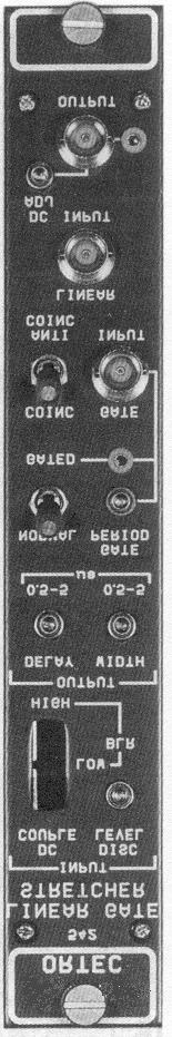
7 1 ORTEC MODEL 542 LINEAR GATE AND STRETCHER 1. DESCRIPTION The ORTEC 542 Linear Gate and Stretcher accepts short duration input pulses and provides output pulses of the same amplitude, but stretched in duration, for applications which have minimum pulse width requirements. This effectively reduces the bandwidth requirements of analog-to-digital converters in multichannel pulse height analyzers and improves the resulting linearity. The linear gate included in the 542 permits selective control of the acceptance of input pulses, and is also used to prevent positive-on-positive pulse pileup. The 542 accepts linear signals, when the input gate is qualified, from any linear source. The input signal is reshaped as required, providing a suitable waveform to a circuit which measures the peak amplitude. Any reshaping of the input pulse must retain the linear parameter of the input signal, which is its relative peak amplitude. The input pulse width is unimportant as long as the peak amplitude duration is long enough to permit accurate response and measurement. The input gate, which can be controlled from an external source, may be operated in either a coincidence or an anticoincidence mode. The Gate Period generator is triggered on the leading edge of a gate input pulse and continues for an effective period set by a front panel adjustment. The Gate Period must overlap the linear input pulse peak for coincidence mode operation or must overlap the discriminator response for anticoincidence mode. An External Strobe Input and switch on the rear panel provide for strobing the output after a peak detect occurs. When the Strobe switch is in external position, an output will be generated in time coincidence with the external strobe signal. The output pulse occurs if and only if a positive logic pulse arrives at the rear panel Strobe Input during the acceptance time as set by the Delay adjustment (10 times the setting) on the front panel. An input pulse must exceed the discriminator level to initiate a response in the 542. When the discriminator fires, it initiates the stretching action unless the gate control is in the external coincidence mode and a gate pulse is not present. The input gate remains open only until the peak of the linear pulse has been detected, and then is again closed to prevent pileup. A delayed output pulse, with selectable width, is generated following the input peak. Both the delay and width adjustments are front panel screwdriver controls on the 542. The input gate cannot be opened again until the output pulse has been completed and the linear input pulse has returned to baseline. This internal logic prevents pulse pileup, therefore enhancing high count rate performance. The 542 can be used in any system to assure an adequate duration of the peak amplitude where a pulse width might otherwise have been too short or where the width variations would produce a nonlinear response or measurement. It may be used at any point in the linear system after a basic linear amplifier. The gate and strobe functions permit logical placement directly after the linear amplifier. 2. SPECIFICATIONS 2.1. PERFORMANCE NOISE CONTRIBUTION <20 µv rms, referred to input. GATE FEEDTHROUGH amplitude with gate closed. <0.05% of signal GATE PEDESTAL Essentially zero, factorycalibrated. STRETCHER DROOP Typically less than 0.1 mv/µs/v output.
8 2 PILEUP REJECTION After the input pulse has reached its peak, subsequent inputs are rejected until both the output pulse has terminated and the input has recovered to the baseline. LINEAR INPUT AMPLITUDE +0.1 to +10V linear range; ±12 V maximum. LINEAR INPUT RISETIME 100 ns to 10 µs. LINEAR OUTPUT WIDTH adjustable. 0.5 TO 5 µs, LINEAR OUTPUT DELAY 0.5 to 5 µs after peak detect, adjustable. GAIN Unity (nominal). INTEGRAL NONLINEARITY <0.2% for pulse risetime >100 ns and pulse width >400 ns. TEMPERATURE INSTABILITY <0.01%/C, 0 to 50C for V o = 5 V. Gain shift COUNTING RATE dc-coupled throughout when DC Couple input is selected. The centroid of a pulser spectrum at 85% of full scale will shift <0.1% when modulated by 5 x 10 4 counts/s of random signals from 137 Cs source-detector combination with photopeak at 70% of full scale (DC Couple mode and amplifier shaping time = 1 µs). When dc restorer modes are used, count rate is dependent on shaping amplifier time constants and pulse undershoot CONTROLS The following controls are on the front panel: INPUT 3-position slide switch, selects input circuit desired: BLR High, BLR Low, or DC Couple. DISC LEVEL Screwdriver potentiometer; adjusts sensitivity level for input discriminator; range +0.1 to +1 V; discriminator remains triggered while input level exceeds adjusted sensitivity. OUTPUT DELAY Screwdriver potentiometer; adjusts delay period from peak detect to start of output pulse; typical range 0.5 to 5 µs. Delay ranges up to 50 µs available on special request. In External Strobe mode, adjusts Acceptance Time; typical range 5 to 50 µs. OUTPUT WIDTH Screwdriver potentiometer adjusts width of the output pulse; typical range 0.5 to 5 µs. NORMAL/GATED Locking-toggle switch selects exclusion (Normal) or inclusion (Gated) of external gating function. GATE PERIOD Screwdriver potentiometer, adjusts duration of gating control from leading edge of Gate Input pulse; range 0.5 to 5 µs; includes test point for monitoring adjusted gate period. OUTPUT DC ADJ Screwdriver potentiometer, permits adjustment of output dc level between ±1.5 V. COINC/ANTICOINC Locking-toggle switch selects effective mode for Gate Input function. The following control is on the rear panel: EXT/INT Locking-toggle switch selects External strobe operation. External Strobe Acceptance Time is adjustable from 5 to 50 µs by the front panel Delay potentiometer INPUTS LINEAR INPUT BNC connector, front panel. Polarity Positive unipolar, or bipolar with positive portion leading. Amplitude +0.1 to +10 V; ±12 V maximum. Risetime 100 ns to 10 µs. Impedance ~1000. GATE INPUT BNC connector, front panel, for optional external control of switch-selectable coincidence or anticoincidence mode triggering. Standard NIM slow logic pulse, triggers selected gate function at +3 V (100 ns minimum width), protected to ±25 V. STROBE INPUT BNC connector, rear panel, for optional external control of the output pulse timing. Standard NIM slow positive logic pulse triggers the strobe functions at +3 V (100 ns minimum width), protected to ±25 V OUTPUTS OUTPUT Front panel BNC connector; furnishes linear positive output pulses through Z o < 1; risetime, 300 ns; includes test point.
9 3 93 OUTPUT Rear panel BNC connector furnishes the linear positive output pulses through Z o =93. Polarity Positive. Amplitude +0.1 to +10 V; equal to peak amplitude of the linear input pulse. Delay Adjust by front panel control; typical range 0.5 to 5 µs after input pulse peak detect. Strobe Acceptance Time range 5 to 50 µs. Width Adjusted by front panel control; range 0.5 to 5 µs typical. Impedance <1 on front panel. DC Offset Adjust ±1.5 V. BUSY OUTPUT Rear panel BNC connector furnishes +5 V nominal through Z o < 10 through all periods when input pulses cannot be accepted; may be used to control external equipment or for monitoring internally created deadtime. Busy, +5 V nominal - linear pulse cannot be accepted. Not Busy, 0 V nominal - linear pulse can be accepted ELECTRICAL AND MECHANICAL POWER REQUIREMENTS +24 V, 83 ma; -24 V, 80 ma; +12 V, 130 ma; -12 V, 30 ma. WEIGHT Shipping 1.9 kg (4 lb). Net 0.9 kg (2 lb). DIMENSIONS NIM-standard single-width module (1.35 by in.) Per TID (Rev). 3. INSTALLATION The 542 contains no internal power supply but is designed for installation in a standard Bin and Power Supply, such as the ORTEC 4001/4002 or 401/402 Series, which are intended for rack mounting. If vacuum tube equipment or other heatproducing equipment is operated in the same rack, there must be adequate circulation of cooling air to prevent any localized heating of the 542 transistorized circuits. The temperature of equipment mounted in racks can easily exceed the recommended maximum unless precautions are observed. The ORTEC 542 should not be subjected to temperatures in excess of 50C (122F) CONNECTION TO POWER Always turn off power for the Bin and Power Supply before inserting or removing any modules. ORTEC NIM instruments are designed so that it is not possible to overload the Power Supply with a full complement of modules in the Bin. Since, however, this may not be true when the Bin contains modules other than those of ORTEC design, check the Power Supply for any overload conditions by testing the dc power levels after all modules are inserted. The ORTEC 542 may be operated outside the Bin and Power Supply, using a power extension cable. Be sure that the cable used accounts properly for the grounding circuits recommended in AEC standards of TID (Rev). Both clean and dirty ground connections are included to ensure proper reference voltage feedback into the Power Supply and must be preserved by the remote cable. Be careful to avoid ground loops when the module is operated outside the Bin LINEAR INPUT CONNECTION Linear input pulses can be furnished from any ORTEC NIM linear module. These include amplifiers, delay circuits, biased amplifiers, gates, and other pulse-handling equipment. It is recommended that the 542 be used ahead of a biased amplifier when both modules are used in a system. The effective input range will be from the adjusted discriminator level (+0.1 to 1 V) up through +10 V. When the linear input signals are furnished through a cable more than 4-ft long (approximately), the input should be terminated with the characteristic impedance of the cable. This can usually be avoided by the use of shorter cable lengths LINEAR OUTPUT CONNECTIONS The shaped linear output pulses can be furnished into any ORTEC NIM linear module or directly into the ADC input of a multichannel analyzer. It is important to preserve the pulse shape and linear amplitude relationship of the output, as it appears at the inputs of subsequent instrument modules. Either of two standard output impedances may be selected according to the type and length of
10 4 interconnecting cable and the input impedance of the instrument to which it is connected. The output is available through a front panel connector, with an output impedance of less than 1., or through a rear panel connector, with Z o = 93. For most applications the 1 front panel Output connector can be used, with a short cable length, to transfer the output signal into the (normally) high input impedance of the next module. When the output signals must be furnished through the cable lengths greater than approximately 4 ft, proper resistive termination of the cable is required in order to preserve the linear output pulses and prevent oscillations. Either of two convenient methods can be selected for the 542 outputs, when termination is required. One method uses a seriestype termination, using the rear panel 93 Output connector and an appropriate length of 93 coaxial cable to transfer the signal into the next module or instrument. The total amplitude of each output pulse will be divided between the 93 output impedance of the 542 and the input impedance of the next module, so a high input impedance is desirable. An alternate method uses shunt termination at the remote end of the cable. For this, use the front panel 1 Output connector and whatever type of coaxial cable is desired. Then use a BNC Tee at the input to the next module to accept both the cable and a BNC Terminator, selected to match the characteristic impedance of the cable when connected in parallel with the instrument s input impedance. For your convenience, ORTEC stocks BNC Tee connectors and both 50 to 100 BNC Terminators GATE INPUT When Gate Input signals are required, they will be furnished through the BNC connector on the front panel of the 542. When selected, a gate input pulse will trigger the 542 Linear Input gate for an adjusted Gate Period. The function may be selected as either Coinc or Anticoinc by a front panel lockingtoggle switch. Gate Input pulses are valid when they exceed +3 V for a period of at least 100 ns. A standard NIM slow logic pulse may be used. The Gate Input circuit is protected to ±25 V; so a wide variety of alternate sources can also be used to initiate this control. When operating in the Coinc mode, the Gate Period must be triggered before the peak of the linear input pulse and must be continued until after the peak. When operating in the Anticoinc mode, the Gate Period must be triggered prior to a discriminator response to the linear input and must be continued until the discriminator has been reset. No Gate Input is required if the front panel Normal/Gated switch is set at Normal. Likewise, if the front panel switches are set at Gated and Anticoinc, a Gate Input pulse is not required except when a linear input signal is to be rejected. When these switches are set for Gated and Coinc, respectively, a linear input pulse will be accepted only if it is accompanied by a time coincident Gate Input pulse EXTERNAL STROBE INPUT The External Strobe Input is a rear panel BNC connector. When the rear panel Strobe switch is set for Ext, an output will be generated only if a standard NIM slow positive logic pulse arrives at the connector during the Strobe Acceptance Time, as set by the front panel Delay potentiometer. The Strobe Acceptance Time is approximately 10 times the Delay setting at a given potentiometer setting. Therefore the Strobe Acceptance Time may be set within a typical range of 5 to 50 µs CONNECTION FOR BUSY OUTPUT The duration of each busy output signal is from the time that an input pulse peak is detected until the resulting output pulse has been furnished and the input discriminator has been reset. This identifies each period during which a new input pulse cannot be accepted in the 542. This output can be integrated externally to indicate relative dead time. 4. OPERATION 4.1. SELECTION OF INPUT CIRCUIT Any of three circuit connections can be selected with the slide switch at the top of the front panel: DC Couple, BLR (Base Line Restorer) Low, or BLR High. The proper selection will depend on the type of output circuit in the module from which the linear input pulses are furnished to the 542 and on the relative counting rate.
11 5 The DC Couple switch position provides an optimum signal transfer circuit with 1000 input impedance if the pulses are furnished from an amplifier with a dc-coupled output and properly adjusted zero baseline. If the source does not include baseline restoration, use a capacitive coupling into the 542 and select either Low or High BLR at the 542. For an ac-coupled signal input, select one of the baseline restorer input circuits in the 542. There is no precise method of input circuit selection because of the various shaping time constants which may be affecting the pulse shape furnished to the 542. For 1-µs pulses the division is approximately 15,000 counts/s. If bipolar pulses are applied to the input, the DC Couple or BLR Low configurations must be selected. The most practical method of selecting between High and Low is observation of the output on an oscilloscope and using the setting that provides the better results DISCRIMINATOR LEVEL ADJUSTMENT The Disc Level adjustment is for the purpose of preventing response to all noise pulses. This threshold voltage should be adjusted high enough in its +0.1 to 1 V range to ensure discrimination against the maximum noise amplitude that may exist at the input to the 542 in the system. The logic in the 542 prevents response to a new input pulse until the Disc Level has been recrossed and the output pulse has been completed. Too high a setting of the Disc Level can permit a small amount of pileup to occur if the input pulse has a very long time constant decay. Although this interference is possible, it is unlikely in most applications. Still an unnecessarily high adjustment is not recommended OUTPUT DELAY AND STROBE ACCEPTANCE TIME ADJUSTMENT The adjustment of the Output Delay permits a control for normalizing timing in the system in which the 542 is included. The delay period is measured from the time that the internal stretch amplifier senses a peak amplitude in the accepted linear input pulse and is typically adjustable through the range of 0.5 to 5 µs. At the end of the delay period the Output Gate is opened and an output pulse is furnished to the next instrument in the system. For Strobed operation, the Delay adjustment becomes a Strobe Acceptance Time adjustment, providing a period of from 5 to 50 µs after linear input peak, during which the strobe signal will cause an output to be generated OUTPUT WIDTH ADJUSTMENT The stretch circuit provides an output pulse of a fixed and known width. The range of the control is typically 0.5 to 5 µs, and its proper setting will be determined by the input requirements of subsequent instruments in the system. Each output pulse will have the adjusted width, regardless of the width of linear pulses furnished to the 542 input OUTPUT DC ADJUSTMENT In normal usage the quiescent level for the output, through both the front and rear panel connectors, should be at ground potential. Use the test point for the front panel Output, and adjust the screwdriver control as necessary to set the level at ground potential when there are no output signals. When the dc input is used on some analyzers it is necessary that the signal source have a quiescent dc level other than zero. When the 542 is used in such applications adjust the output dc level as required GATED OPERATION No Gate Input pulse is required if the front panel slide switch is set at Normal. Likewise, if the slide switch is set at Gated and the mode selector on the front panel is set for Anticoinc, linear input pulses will be accepted when there is no signal through the Gate Input connector. Whenever a signal is furnished through the Gate Input with Gated Anticoinc effective, all linear input signals are inhibited throughout the Gate Period. To be effective, the Gate Period must be adjusted to overlap the period of discriminator response to any pulse that is to be inhibited by the Anticoinc signal; if the linear input triggers the discriminator before the Gate Input or if the Gate Period terminates prior to discriminator recovery, there will be an output, but the amplitude will probably not duplicate the peak input amplitude. When the 542 is set for gated coincidence operation, a linear input signal is accepted for stretching if and only if there is a time-coincident Gate Input. The Gate Input signal must occur before the peak amplitude of the linear input pulse,
12 6 and the Gate Period must be long enough to continue the control beyond the internal detection of the peak amplitude. Refer to Section 5.2 for linear gate pedestal adjustment procedures STROBED OPERATION When the 542 is to be used in Externally Strobed mode, the rear panel INT/EXT locking-toggle switch is placed in EXT position. The strobing device is connected via the External Strobe BNC connector on the rear panel. In Externally Strobed Mode, an output will be generated only if a standard NIM slow positive logic pulse arrives at the External Strobe connector within the Strobe Acceptance Time (range 5-50 µs) as set by the front panel potentiometer labeled Output Delay OVERALL LOGIC When the amplitude of an input pulse exceeds the discriminator threshold, the discriminator may be fired or it may still be set because of not having recovered from a previous input pulse. The linear input pulse will not be accepted unless the discriminator has recovered prior to the new pulse; it will also be rejected if (1) an output pulse has not been completed for a previously accepted input; (2) the operating mode is gated coincidence and no Gate Input has been furnished; (3) the operating mode is gated anticoincidence, a Gate Input signal has been furnished, and the Gate Period is in effect; or (4) in the External Strobe mode and no strobe signal is present during the Strobe Acceptance Time. When the discriminator recovers, it will permit the input to be gated on unless (1) the output pulse has not been completed or (2) External Gate Input logic has closed the linear input circuit. When the output pulse has been completed, the linear input is qualified unless (1) the discriminator is not reset or (2) External Gate Input logic has closed the linear input circuit. When the discriminator is triggered prior to a Coincidence Gate Input but the linear input is otherwise qualified, the linear input signal is not applied to the stretch circuit until the Gate Input signal is furnished. Under these conditions, the linear input signal is applied to the stretch circuit at the Gate Input time; an output signal will result, which has an amplitude equal to (1) the peak input amplitude or (2) the input amplitude at the end of the adjusted Gate Period (whichever occurs first). Thus, it is important that the gate be triggered during the risetime of the linear input pulse and that it remain effective until after the peak amplitude has been sensed. 5. MAINTENANCE 5.1. TESTING PERFORMANCE OF PULSE STRETCHER The following paragraphs are intended as an aid in the installation and checkout of the 542. These instructions present information on waveforms at test points and output connectors. Test Equipment The following, or equivalent, test equipment is needed. ORTEC 419 Pulse Generator 50-MHZ Bandwidth Oscilloscope 100 BNC Terminators Digital Voltmeter ORTEC Pulse Shaping Amplifier Preliminary Procedures Visually check the module for possible damage due to shipment and then perform the following steps: 1. Connect ac power to NIM standard Bin and Power Supply, ORTEC 4001/4002 or 401/ Plug module into Bin and check for proper mechanical alignment. 3. Switch ac power on and check the dc Power Supply voltages at the test points on the Bin Power Supply control panel. Pulse Stretcher The following procedure will check the performance of the Pulse Stretcher: 1. Feed the output of the 419 Pulse Generator into the input of the Amplifier.
13 7 2. Set the Amplifier controls for a gain of approximately 200 with equal integration and differentiation time constants. 3. Set the 542 Input switch to DC Couple, the Gate switch to Normal, and the Strobe switch to Int. 4. Adjust the 419 Pulse Generator for a 100-mV pulse from the unipolar output of the Amplifier. 5. Feed the 100-mV unipolar output of the Amplifier into the input of the 542. Load the 542 output with a 100 terminator. 6. Adjust the discriminator time potentiometer on the front panel until triggering of the stretcher circuit just occurs, as evidenced by an output pulse from the Increase the input signal to the 542 (by adjusting the 419 Pulse Generator) to 500 mv. 8. The output of the 542 should have a peak amplitude of 500 ± 25 mv (see Linear Gate Pedestal Adjustment Procedure in Section 6.2 if these limits are exceeded); the top of the pulse should exhibit a smooth slope of less than 0.5 mv/µs. 9. Increase the input signal to the 542 to 10 V; the output should be essentially 10 V. 10. The time at which the output occurs should be adjustable from approximately 0.5 to 5 µs after peak detect. The duration of the output waveform should be adjustable over the range of approximately 0.5 to 5 µs. 11. Select the Gated and Coinc positions on the front panel switches. The 542 output should disappear. 12. Select the Anticoinc position and the 542 output should reappear. (A more complete check of the 542 Gate can be made if a logic pulse in time coincidence with the linear input pulse is available.) 13. Increase the input to the 542 to the saturation level of the amplifier, approximately 12 V; the output of the 542 should be greater than 10.5 V. 14. Connect the amplifier output to the 542 Gate Input and monitor the Gate Period pulse with an oscilloscope. The Gate Period should be adjustable from approximately 0.5 to 5 µs. Pulse Pileup Test A dual or variable highfrequency pulser is needed to check the operation of the 542 pileup circuit. 1. Connect a dual or variable high-frequency pulser to the 542 input. 2. Monitor the 542 input and output simultaneously with an oscilloscope. 3. Adjust the output delay and width controls to full clockwise positions. 4. Gradually decrease the time interval between the input pulses. 5. The second pulse should be blocked by the 542 when the time interval between the peaks of two consecutive pulses is short enough to cause pileup greater than the discriminator threshold CALIBRATION PROCEDURES Linear Gate Pedestal Adjustment The input and output gates are shunt-type gates which clamp the signal line to ground. If the signal line is not at ground potential in the quiescent condition, then a pedestal is introduced by the gating action. This can be avoided by adjusting the output of the Buffer Amplifier (TP1) to zero volts and then adjusting the output of the Stretch Amplifier (TP2) to zero volts. Use the following procedure when making this adjustment: 1. Set the input gate switch to Normal and the strobe switch to Int. 2. Set the Input switch to the mode desire. If the DC Couple position is used, ensure that the dc level of the amplifier driving the 542 is set to zero volts. 3. Monitor TP1 with a digital voltmeter and adjust R7, on the front of the printed circuit board, to obtain zero volts at TP1. 4. When the Input switch is moved to either of the other two positions, the voltage at TP1 should remain at 0 V ± 20 mv. 5. Monitor TP2 with the voltmeter and adjust R18 to obtain zero volts at TP2. The 542 is now adjusted for a zero pedestal. These adjustments must be made regardless of whether or not the linear gating function of the 542 is being used. CAUTION: If the Input switch is set to DC Couple and the output dc level of the Amplifier driving the 542 is not set at zero volts, the 542 will appear to have a pedestal since the 542 gate circuit will be gating a dc voltage. Discriminator Adjustment The 542 Disc Level should be set well above the system noise because each pulse that exceeds the discriminator level will be stretched, whether it be noise or a legitimate signal. If the Disc Level is set far below the
14 8 system s noise, the 542 pileup rejection circuit may completely block the input and prevent any outputs from occurring. Normally a discriminator level of 100 mv is adequate. A precise discriminator setting can be made by the following procedure: 1. Apply a 0.5-µs shaped; signal to the 542 input with amplitude equal to the desired Disc Level setting. 2. Monitor the 542 input and output signals with an oscilloscope. 3. Adjust the 542 discriminator control (front panel) until the number of output pulses is approximately equal to one-half the number of input pulses. The discriminator is now properly adjusted SUGGESTIONS FOR TROUBLESHOOTING In situations where the 542 is suspected of malfunction, it is essential to verify such malfunction in terms of simple pulse generator impulses at the input. In consideration of this, the 542 must be disconnected from its position in any system and routine diagnostic analysis be performed with a test pulse generator and oscilloscope. It is important that testing not be performed with a source and detector until the amplifier-pulse stretcher system performs satisfactorily with the test pulse detector. The testing instructions in Section 5.1 of this manual should provide assistance in locating the region of trouble and repairing the malfunction. The two side plates can be completely removed from the module to enable oscilloscope and voltmeter observations with a minimal chance of accidentally short-circuiting portions of the etched board. If the problem involves an inability to get an output pulse, there are several solutions: 1. If Input switch is in the DC Couple position, switch to low or high positions. If output appears, a dc level is probably being applied to the 542 input and locking up the pulse pileup circuit. Adjust the output dc level of the amplifier during the 542 to zero volts. 2. Adjust the Disc Level fully clockwise. If an output occurs, the discriminator was probably set below the system noise level, locking up the pileup circuit. 3. If operating in the Gated mode, switch to the Normal mode. If an output occurs, the gating logic is probably not in time coincidence with the linear pulse. 4. If operated in Gated or Normal mode, check that Strobe switch is in Int position FACTORY REPAIR SERVICE The 542 may be returned to ORTEC for repair service at nominal cost. Our standard procedure requires that each repaired instrument receive the same extensive quality control tests that a new instrument receives. Contact our Customer Service Department, (865) , for shipping instructions before returning the instrument. The unit will be assigned a Return Authorization Number which must accompany the returned instrument.
15 9 Bin/Module Connector Pin Assignments For Standard Nuclear Instrument Modules per DOE/ER-0457T. Pin Function Pin Function 1 +3 V 23 Reserved 2-3 V 24 Reserved 3 Spare bus 25 Reserved 4 Reserved bus 26 Spare 5 Coaxial 27 Spare 6 Coaxial * V 7 Coaxial *29-24 V V dc 30 Spare bus 9 Spare 31 Spare *10 +6 V 32 Spare *11-6 V * V ac (hot) 12 Reserved bus *34 Power return ground 13 Spare 35 Reset (Scaler) 14 Spare 36 Gate 15 Reserved 37 Reset (Auxiliary) * V 38 Coaxial *17-12 V 39 Coaxial 18 Spare bus 40 Coaxial 19 Reserved bus * V ac (neutral) 20 Spare *42 High-quality ground 21 Spare G Ground guide pin 22 Reserved Pins marked (*) are installed and wired in ORTEC s 4001A and 4001C Modular System Bins.
16 10
Model 9302 Amplifier-Discriminator Operating and Service Manual
 Model 9302 Amplifier-Discriminator Operating and Service Manual Printed in U.S.A. ORTEC Part No. 733690 1202 Manual Revision C Advanced Measurement Technology, Inc. a/k/a/ ORTEC, a subsidiary of AMETEK,
Model 533 Dual Sum and Invert Amplifier Operating and Service Manual
 Model 533 Dual Sum and Invert Amplifier Operating and Service Manual Printed in U.S.A. ORTEC Part No. 733410 1202 Manual Revision B Advanced Measurement Technology, Inc. a/k/a/ ORTEC, a subsidiary of AMETEK,
Model 427A Delay Amplifier Operating and Service Manual
 Model 427A Delay Amplifier Operating and Service Manual This manual Applies to instruments marked Rev 22" on rear panel Printed in U.S.A. ORTEC Part No. 733210 1202 Manual Revision B Advanced Measurement
Model 863 Quad Timing Filter Amplifier Operating and Service Manual
 Model 863 Quad Timing Filter Amplifier Operating and Service Manual Printed in U.S.A. ORTEC Part No. 733960 0411 Manual Revision C Advanced Measurement Technology, Inc. a/k/a/ ORTEC, a subsidiary of AMETEK,
Model 416A Gate and Delay Generator Operating and Service Manual
 Model 416A Gate and Delay Generator Operating and Service Manual Printed in U.S.A. ORTEC Part No. 733160 1202 Manual Revision E Advanced Measurement Technology, Inc. a/k/a/ ORTEC, a subsidiary of AMETEK,
Model 9305 Fast Preamplifier Operating and Service Manual
 Model 9305 Fast Preamplifier Operating and Service Manual This manual applies to instruments marked Rev 03" on rear panel. Printed in U.S.A. ORTEC Part No.605540 1202 Manual Revision B Advanced Measurement
Model 113 Scintillation Preamplifier Operating and Service Manual
 Model 113 Scintillation Preamplifier Operating and Service Manual Printed in U.S.A. ORTEC Part No. 717560 1202 Manual Revision B Advanced Measurement Technology, Inc. a/k/a/ ORTEC, a subsidiary of AMETEK,
Model 426 Linear Gate Operating and Service Manual
 Model 426 Linear Gate Operating and Service Manual This manual applies to instruments marked Rev 23" on rear panel Printed in U.S.A. ORTEC Part No. 733200 1202 Manual Revision B Advanced Measurement Technology,
Model 428 Detector Bias Supply Operating and Service Manual
 Model 428 Detector Bias Supply Operating and Service Manual Printed in U.S.A. ORTEC Part No. 733220 1202 Manual Revision C Advanced Measurement Technology, Inc. a/k/a/ ORTEC, a subsidiary of AMETEK, Inc.
ScintiPack Model 296 Photomultiplier Base with Preamplifier and High Voltage Power Supply Operating and Service Manual
 ScintiPack Model 296 Photomultiplier Base with Preamplifier and High Voltage Power Supply Operating and Service Manual WARNING This equipment generates, uses, and can radiate radio frequency energy, and
Model 449 Log/Lin Ratemeter Operating and Service Manual
 Model 449 Log/Lin Ratemeter Operating and Service Manual Printed in U.S.A. ORTEC Part No. 733270 1202 Manual Revision D Advanced Measurement Technology, Inc. a/k/a/ ORTEC, a subsidiary of AMETEK, Inc.
Model 439 Digital Current Integrator Operating Manual
 Model 439 Digital Current Integrator Operating Manual Printed in U.S.A. ORTEC Part No. 733240 0908 Manual Revision K Advanced Measurement Technology, Inc. a/k/a/ ORTEC, a subsidiary of AMETEK, Inc. WARRANTY
Model 480 Pulser Operating and Service Manual
 Model 480 Pulser Operating and Service Manual Printed in U.S.A. ORTEC Part No. 733390 1202 Manual Revision B Advanced Measurement Technology, Inc. a/k/a/ ORTEC, a subsidiary of AMETEK, Inc. WARRANTY ORTEC*
Model 566 Time-to-Amplitude Converter (TAC) Operating and Service Manual
 Operating and Service Manual") Model 566 Time-to-Amplitude Converter (TAC) Operating and Service Manual Printed in U.S.A. ORTEC Part No. 678950 0411 Manual Revision F Advanced Measurement Technology, Inc. a/k/a/ ORTEC, a subsidiary
Model 566 Time-to-Amplitude Converter (TAC) Operating and Service Manual Printed in U.S.A. ORTEC Part No. 678950 0411 Manual Revision F Advanced Measurement Technology, Inc. a/k/a/ ORTEC, a subsidiary
Model 935 Quad Constant-Fraction 200-MHz Discriminator Operating and Service Manual
 Model 935 Quad Constant-Fraction 200-MHz Discriminator Operating and Service Manual U.S. Patent No. 4,179,644 Printed in U.S.A. ORTEC Part No. 753770 0503 Manual Revision H ii $GYDQFHG0HDVXUHPHQW7HFKQRORJ\,QF
Model 9307 pico-timing Discriminator Operating and Service Manual
 Model 9307 pico-timing Discriminator Operating and Service Manual Printed in U.S.A. ORTEC Part No. 764020 1202 Manual Revision C Advanced Measurement Technology, Inc. a/k/a/ ORTEC, a subsidiary of AMETEK,
Model 276L Low-Power Photomultiplier Base Operating and Service Manual
 Model 276L Low-Power Photomultiplier Base Operating and Service Manual Printed in U.S.A. ORTEC Part No. 762870 0702 Manual Revision C $GYDQFHG 0HDVXUHPHQW 7HFKQRORJ\,QF a/k/a/ ORTEC, a subsidiary of AMETEK,
Model 673 Spectroscopy Amplifier and Gated Integrator Operating and Service Manual
 Model 673 Spectroscopy Amplifier and Gated Integrator Operating and Service Manual Printed in U.S.A. ORTEC Part No. 675590 0202 Manual Revision B $GYDQFHG 0HDVXUHPHQW 7HFKQRORJ\,QF a/k/a/ ORTEC, a subsidiary
Model 142AH Preamplifier Operating and Service Manual
 Model 142AH Preamplifier Operating and Service Manual Printed in U.S.A. ORTEC Part No. 733990 0202 Manual Revision B $GYDQFHG 0HDVXUHPHQW 7HFKQRORJ\,QF a/k/a/ ORTEC, a subsidiary of AMETEK, Inc. WARRANTY
Model 7000 Low Noise Differential Preamplifier
 Model 7000 Low Noise Differential Preamplifier Operating Manual Service and Warranty Krohn-Hite Instruments are designed and manufactured in accordance with sound engineering practices and should give
Model 855 Dual Spectroscopy Amplifier Operating and Service Manual
 Model 855 Dual Spectroscopy Amplifier Operating and Service Manual This manual applies to instruments marked Rev. 03" on rear panel. Printed in U.S.A. ORTEC Part No. 717490 0406 Manual Revision C $GYDQFHG0HDVXUHPHQW7HFKQRORJ\,QF
Model 460 Delay Line Amplifier Operating and Service Manual
 Model 460 Delay Line Amplifier Operating and Service Manual Printed in U.S.A. ORTEC Part No. 733320 1202 Manual Revision C Advanced Measurement Technology, Inc. a/k/a/ ORTEC, a subsidiary of AMETEK, Inc.
INSTRUCTION MANUAL. March 11, 2003, Revision 3
 INSTRUCTION MANUAL Model 701A Stimulator March 11, 2003, Revision 3 Copyright 2003 Aurora Scientific Inc. Aurora Scientific Inc. 360 Industrial Parkway S., Unit 4 Aurora, Ontario, Canada L4G 3V7 Tel: 1-905-727-5161
2001A. 200KHz Function Generator Instruction Manual. 99 Washington Street Melrose, MA Phone Toll Free
 2001A 200KHz Function Generator Instruction Manual 99 Washington Street Melrose, MA 02176 Phone 781-665-1400 Toll Free 1-800-517-8431 Visit us at www.testequipmentdepot.com WARRANTY Global Specialties
Model Hz to 10MHz Precision Phasemeter. Operating Manual
 Model 6610 1Hz to 10MHz Precision Phasemeter Operating Manual Service and Warranty Krohn-Hite Instruments are designed and manufactured in accordance with sound engineering practices and should give long
Dual 500ns ADC User Manual
 7072 Dual 500ns ADC User Manual copyright FAST ComTec GmbH Grünwalder Weg 28a, D-82041 Oberhaching Germany Version 2.3, May 11, 2009 Copyright Information Copyright Information Copyright 2001-2009 FAST
Model 2145 Time to Amplitude Converter
 9231617B Model 2145 Time to Amplitude Converter User s Manual Copyright 2005, Canberra Industries, Inc. All rights reserved. The material in this document, including all information, pictures, graphics
Analog-to-Digital-Converter User Manual
 7070 Analog-to-Digital-Converter User Manual copyright FAST ComTec GmbH Grünwalder Weg 28a, D-82041 Oberhaching Germany Version 2.0, July 7, 2005 Software Warranty FAST ComTec warrants proper operation
PCO-7114 Laser Diode Driver Module Operation Manual
 PCO-7114 Laser Diode Driver Module Operation Manual Directed Energy, Inc. 1609 Oakridge Dr., Suite 100, Fort Collins, CO 80525, (970) 493-1901 sales@ixyscolorado.com www.ixyscolorado.com Manual Document
AMP-13 OPERATOR S MANUAL
 AMP-13 OPERATOR S MANUAL Version 2.0 Copyright 2008 by Vatell Corporation Vatell Corporation P.O. Box 66 Christiansburg, VA 24068 Phone: (540) 961-3576 Fax: (540) 953-3010 WARNING: Read instructions carefully
Directed Energy, Inc Oakridge Dr., Suite 100, Fort Collins, CO
 PCO-7121 Laser Diode Driver Module Operation Manual Directed Energy, Inc. 1609 Oakridge Dr., Suite 100, Fort Collins, CO 80525 sales@ixyscolorado.com www.ixyscolorado.com Contents Contents... 3 Safety...
CLEANING CALIBRATION INTERVAL
 &DUHDQG0DLQWHQDQFH! &DUHDQG0DLQWHQDQFH CLEANING CALIBRATION INTERVAL SERVICE STRATEGY TROUBLESHOOTING A. Trace Off Scale The exterior of the probe and cable should be cleaned only using a soft cloth moistened
TRANSDUCER IN-LINE AMPLIFIER
 TRANSDUCER IN-LINE Voltage Model AMPLIFIER 2080 Arlingate, Columbus, Ohio 43228, (614) 850-5000 Sensotec, Inc. 2080 Arlingate Lane Columbus, Ohio 43228 Copyright 1995 by Sensotec, Inc. all rights reserved
Glass Electrode Meter
 Glass Electrode Meter INSTRUCTION MANUAL FOR Glass Electrode R/C Meter MODEL 2700 Serial # Date PO Box 850 Carlsborg, WA 98324 U.S.A. 360-683-8300 800-426-1306 FAX: 360-683-3525 http://www.a-msystems.com
P5100A & P5150 High Voltage Probes Performance Verification and Adjustments
 x P5100A & P5150 High Voltage Probes Performance Verification and Adjustments ZZZ Technical Reference *P077053001* 077-0530-01 xx P5100A & P5150 High Voltage Probes Performance Verification and Adjustments
OPERATION & SERVICE MANUAL FOR FC 110 AC POWER SOURCE
 OPERATION & SERVICE MANUAL FOR FC 100 SERIES AC POWER SOURCE FC 110 AC POWER SOURCE VERSION 1.3, April 2001. copyright reserved. DWG No. FC00001 TABLE OF CONTENTS CHAPTER 1 INTRODUCTION... 1 1.1 GENERAL...
BC145 SIGNAL ISOLATOR BOARD
 BC145 SIGNAL ISOLATOR BOARD 4/17 Installation & Operating Manual MN1373 Any trademarks used in this manual are the property of their respective owners. Important: Be sure to check www.baldor.com to download
Current Probes. User Manual
 Current Probes User Manual ETS-Lindgren Inc. reserves the right to make changes to any product described herein in order to improve function, design, or for any other reason. Nothing contained herein shall
Amptek sets the New State-of-the-Art... Again! with Cooled FET
 Amptek sets the New State-of-the-Art... Again! with Cooled FET RUN SILENT...RUN FAST...RUN COOL! Performance Noise: 670 ev FWHM (Si) ~76 electrons RMS Noise Slope: 11.5 ev/pf High Ciss FET Fast Rise Time:
201AP Charge Amplifier User Manual
 Trig-Tek 201AP Charge Amplifier User Manual Publication No. 980996 Rev. A Astronics Test Systems Inc. 4 Goodyear, Irvine, CA 92618 Tel: (800) 722-2528, (949) 859-8999; Fax: (949) 859-7139 atsinfo@astronics.com
MODEL W Power Amplifier
 TEGAM, INC. MODEL 2348 18.75 W Power Amplifier This owner s manual was as current as possible when this product was manufactured. However, products are constantly being updated and improved. Because of
305 Stimulus Isolator. Description
 Description The Model 305 Stimulus Isolator utilizes photon coupling to provide nearly ideal isolation of the pulse and train outputs of the WPI Series 300 Anapulse Stimulators. Two Model 305 units are
Broadband Step-Up Transformer. User Manual
 Broadband Step-Up Transformer User Manual 990-1930 09/2004 Introduction Introduction About this unit The APC Step-Up Transformer provides 220 V power from 60 VAC Broadband cable systems. Safety Electrical
Model MV106J/MV116J. ±10nVdc to ±11Vdc Precision DC Voltage Standard Source. Operating Manual
 Model MV106J/MV116J ±10nVdc to ±11Vdc Precision DC Voltage Standard Source Operating Manual This page intentionally left blank. MV 106 & MV116 OPERATORS MANUAL Serial No. Win-man\mvman.wpd This page intentionally
Quad Analog-to-Digital Converter Technical Documentation
 7074 Quad AnalogtoDigital Converter Technical Documentation copyright FAST ComTec GmbH Grünwalder Weg 28a, D82041 Oberhaching Germany Version 2.2, February 25, 2005 Table of Contents Table of Contents
Model 5100F. Advanced Test Equipment Rentals ATEC (2832) OWNER S MANUAL RF POWER AMPLIFIER
 OWNER S MANUAL RF POWER AMPLIFIER") Established 1981 Advanced Test Equipment Rentals www.atecorp.com 800-404-ATEC (2832) OWNER S MANUAL Model 5100F RF POWER AMPLIFIER 0.8 2.5 GHz, 25 Watts Ophir RF 5300 Beethoven Street Los Angeles, CA 90066
Established 1981 Advanced Test Equipment Rentals www.atecorp.com 800-404-ATEC (2832) OWNER S MANUAL Model 5100F RF POWER AMPLIFIER 0.8 2.5 GHz, 25 Watts Ophir RF 5300 Beethoven Street Los Angeles, CA 90066
RIGOL. User s Guide. RP5600 Passive Probe. July 2010 RIGOL Technologies, Inc.
 User s Guide RP5600 Passive Probe July 2010 RIGOL Technologies, Inc. Guaranty and Declaration Copyright 2010 RIGOL Technologies, Inc. All Rights Reserved. Trademark Information RIGOL is a registered trademark
VT1586A Rack Mount Terminal Panel Installation and User s Manual
 VT1586A Rack Mount Terminal Panel Installation and User s Manual Manual Part Number: 82-0095-000 Rev. June 16, 2003 Printed in U.S.A. Certification VXI Technology, Inc. certifies that this product met
AMP-12 OPERATOR S MANUAL
 AMP-12 OPERATOR S MANUAL Version 1.0 Copyright 2002 by Vatell Corporation Vatell Corporation P.O. Box 66 Christiansburg, VA 24068 Phone: (540) 961-3576 Fax: (540) 953-3010 WARNING: Read instructions carefully
CSM-S USER S MANUAL TRIGGER DISTRIBUTION MODULE Release April 7, VXI Technology, Inc.
 CSM-S-11056 TRIGGER DISTRIBUTION MODULE USER S MANUAL 82-0051-000 Release April 7, 2003 VXI Technology, Inc. 2031 Main Street Irvine, CA 92614-6509 (949) 955-1894 bus 2 VXI Technology, Inc. www.vxitech.com
HP 86290B RF PLUG-IN GHz HEWLETT PACKARD
 OPERATING AND SERVICE MANUAL. HP 86290B RF PLUG-IN 2.0-18.6 GHz HEWLETT PACKARD COPYRIGHT AND DISCLAIMER NOTICE Copyright - Agilent Technologies, Inc. Reproduced with the permission of Agilent Technologies
An American Control Electronics Brand PCM4 SERIES USER MANUAL PCM4.
 An American Control Electronics Brand PCM4 SERIES PCM4 USER MANUAL www.minarikdrives.com Dear Valued Consumer: Congratulations on your purchase of the PCM4 Series isolation card. This User Manual was created
DUAL CHANNEL BROADBAND LINEAR AMPLIFIER Model A800D
 DUAL CHANNEL BROADBAND LINEAR AMPLIFIER Model A800D HIGH VOLTAGE FIXED GAIN BROADBAND 800Vpp 60mA 100x DC to ca 200 khz LOW OUTPUT IMPEDANCE HIGH SLEW RATE
TEGAM, INC. SINGLE/DUAL CHANNEL HIGH VOLTAGE AMPLIFIER MODEL 2340/2350. Instruction Manual PN# CD Publication Date: June 2006 REV.
 TEGAM, INC. SINGLE/DUAL CHANNEL HIGH VOLTAGE AMPLIFIER MODEL 2340/2350 Instruction Manual PN# 810044-CD Publication Date: June 2006 REV. C This owner s manual was as current as possible when this product
SUBNANOSECOND PULSE GENERATOR PPG-2/1000 USER MANUAL
 SUBNANOSECOND PULSE GENERATOR PPG-2/1000 USER MANUAL 2015 Megaimpulse Ltd. Copyright 2015 MEGAIMPULSE Ltd. All Rights Reserved. MEGAIMPULSE LTD. PROVIDES THIS MANUAL "AS IS" WITHOUT WARRANTY OF ANY KIND,
NANOSECOND PULSE GENERATOR NPG-18/3500(N) USER MANUAL
 USER MANUAL") NANOSECOND PULSE GENERATOR NPG-18/3500(N) USER MANUAL 2014 Megaimpulse Ltd. Copyright 2013 MEGAIMPULSE Ltd. All Rights Reserved. MEGAIMPULSE LTD. PROVIDES THIS MANUAL "AS IS" WITHOUT WARRANTY OF ANY KIND,
NANOSECOND PULSE GENERATOR NPG-18/3500(N) USER MANUAL 2014 Megaimpulse Ltd. Copyright 2013 MEGAIMPULSE Ltd. All Rights Reserved. MEGAIMPULSE LTD. PROVIDES THIS MANUAL "AS IS" WITHOUT WARRANTY OF ANY KIND,
TRANSDUCER IN-LINE AMPLIFIER
 TRANSDUCER IN-LINE Bi-Polar Model AMPLIFIER 2080 Arlingate Lane, Columbus, Ohio 43228 (614) 850-5000 Sensotec, Inc. 2080 Arlingate Lane Columbus, Ohio 43228 Copyright 1995 by Sensotec, Inc. all rights
P5100A & P5150 High Voltage Probes Performance Verification and Adjustments
 x P5100A & P5150 High Voltage Probes Performance Verification and Adjustments ZZZ Technical Reference *P077053002* 077-0530-02 xx P5100A & P5150 High Voltage Probes Performance Verification and Adjustments
PDB4. Four Channel Passive Direct Box USER'S GUIDE
 PDB4 Four Channel Passive Direct Box USER'S GUIDE IMPORTANT SAFETY INSTRUCTIONS - READ FIRST This symbol, wherever it appears, alerts you to important operating and maintenance instructions in the accompanying
Model Operating Manual
 Model 7500 DC to 1MHz Wideband Power Amplifier Operating Manual Copyright 2004. All rights reserved. Contents of this publication may not be reproduced in any form without the written permission of Krohn-Hite
PARALLEL MULTI-AMP KIT for 7200 Series AMPLIFIERS INSTRUCTION SHEET
 2 5 0 7 W a r r e n S t r e e t, E l k h a r t, I N 4 6 5 1 6 U S A 5 7 4. 2 9 5. 9 4 9 5 w w w. A E T e c h r o n. c o m PARALLEL MULTI-AMP KIT for 7200 Series AMPLIFIERS INSTRUCTION SHEET Kit Contents:
LUDLUM MODEL MODEL AND MODEL GAMMA SCINTILLATORS. June 2017
 LUDLUM MODEL 44-20 MODEL 44-20-1 AND MODEL 44-20-3 GAMMA SCINTILLATORS June 2017 LUDLUM MODEL 44-20 MODEL 44-20-1 AND MODEL 44-20-3 GAMMA SCINTILLATORS June 2017 STATEMENT OF WARRANTY Ludlum Measurements,
INSTRUCTION MANUAL INF Fax: (503)
") INSTRUCTION MANUAL INF151 1-800-547-5740 Fax: (503) 643-6322 www.ueiautomotive.com email: info@ueitest.com Introduction Congratulations on your purchase of the INF151 infrared thermometer. Like all UEi
INSTRUCTION MANUAL INF151 1-800-547-5740 Fax: (503) 643-6322 www.ueiautomotive.com email: info@ueitest.com Introduction Congratulations on your purchase of the INF151 infrared thermometer. Like all UEi
CANARY AUDIO. Power Amplifier CA-309 OWNER S MANUAL. Handcrafted in California MADE IN USA
 CANARY AUDIO 300B Push-Pull Parallel Power Amplifier Mono Block Handcrafted in California CA-309 OWNER S MANUAL MADE IN USA Dear Customer: Please allow us to take this opportunity to thank you for purchasing
2015 RIGOL TECHNOLOGIES, INC.
 Service Guide DG000 Series Dual-channel Function/Arbitrary Waveform Generator Oct. 205 TECHNOLOGIES, INC. Guaranty and Declaration Copyright 203 TECHNOLOGIES, INC. All Rights Reserved. Trademark Information
Model 1791 VHF Radio User's Manual
 Model 79 VHF Radio User's Manual ALL WEATHER INC 65 NATIONAL DRIVE SACRAMENTO, CA 95834 WWW.ALWEATHERINC.COM 79 VHF RADIO USER'S MANUAL CONTENTS INTRODUCTION... Description... Transmitter Module... Power
ORTEC Experiment 1. Introduction to Electronic Signal Analysis in Nuclear Radiation Measurements. Equipment Required: Purpose. Electronic Circuits
 ORTEC Experiment 1 Equipment Required: 480 Pulser 113 Scintillation Preamplifier 4001A/4002D NIM Bin and Power Supply 575A Spectroscopy Amplifier 996 Timer and Counter 551 Timing Single-Channel Analyzer
Model 8140VT VERSATAP INSTALLATION AND OPERATION MANUAL
 VERSATAP INSTALLATION AND OPERATION MANUAL 95 Methodist Hill Drive Rochester, NY 14623 Phone: US +1.585.321.5800 Fax: US +1.585.321.5219 www.spectracomcorp.com Part Number 8147-5000-0050 Manual Revision
User s Manual. Ground Resistance Clamp On Tester MODEL
 User s Manual Ground Resistance Clamp On Tester MODEL 382357 Warranty EXTECH INSTRUMENTS CORPORATION warrants the basic instrument to be free of defects in parts and workmanship for one year from date
ADA416-XLR DISTRIBUTION AMPLIFIERS OPERATING AND MAINTENANCE MANUAL
 ADA416-XLR DISTRIBUTION AMPLIFIERS OPERATING AND MAINTENANCE MANUAL Copyright 2015, ATI Audio Inc. DESCRIPTION Your ADA416-XLR provides four independent one-in by four-out circuit groups. A four-output
CALIBRATED IMPULSE GENERATOR MODEL CIG khz 1 GHz
 INSTRUCTION MANUAL CALIBRATED IMPULSE GENERATOR MODEL CIG-25 10 khz 1 GHz INSTRUCTION MANUAL THIS INSTRUCTION MANUAL AND ITS ASSOCIATED INFORMATION IS PROPRIETARY. UNAUTHORIZED REPRODUCTION IS FORBIDDEN.
LeCroy Research Systems Model 365AL, Model 465, and Model 622 Logic Units
 Page 1 of 5 365AL DUAL 4-FOLD MAJORITY LOGIC UNIT 465 TRIPLE 4-FOLD LOGIC UNIT (Note - the 465 is no longer available) 622 QUAD 2 LOGIC UNIT NIM Packaging High Speed Multiple Input Multiple Output Selectable
200B Clipper Module User Manual
 Trig-Tek 200B Clipper Module User Manual Publication No. 980954 Rev. A Astronics Test Systems Inc. 4 Goodyear, Irvine, CA 92618 Tel: (800) 722-2528, (949) 859-8999; Fax: (949) 859-7139 atsinfo@astronics.com
Instruction Manual CT-6 High Frequency AC Current Probe
 Instruction Manual CT-6 High Frequency AC Current Probe 071-0453-00 Revision A Copyright Tektronix, Inc. All rights reserved. Tektronix products are covered by U.S. and foreign patents, issued and pending.
DUAL%CHANNEL%LINEAR%AMPLIFIER %WITH%PHASE%INVERTER Model&A400DI
 ELECTRONICS AB DUAL%CHANNEL%LINEAR%AMPLIFIER %WITH%PHASE%INVERTER ModelA400DI HIGHVOLTAGE FIXEDGAIN BROADBAND ±200V 150mA 20x DCtoca500kHz FULLSCALE LOWOUTPUTIMPEDANCE HIGHSLEWRATE
Operation and Service Manual. 350 MHz Preamplifier SIM914. Stanford Research Systems
 Operation and Service Manual Stanford Research Systems Revision 1.8 August 24, 2006 Certification Stanford Research Systems certifies that this product met its published specifications at the time of shipment.
LUDLUM MODEL 421 AND PMT BASE WITH PREAMPLIFIER/BIAS SUPPLY. October 2014 Serial Number and Succeeding Serial Numbers
 LUDLUM MODEL 421 AND 421-3 PMT BASE WITH PREAMPLIFIER/BIAS SUPPLY October 2014 Serial Number 200000 and Succeeding Serial Numbers LUDLUM MODEL 421 AND 421-3 PMT BASE WITH PREAMPLIFIER/BIAS SUPPLY October
BROADBAND'LINEAR'AMPLIFIER WITH'A±B'INPUTS'AND'DC5OFFSET Model&A400X
 ELECTRONICS AB BROADBAND'LINEAR'AMPLIFIER WITH'A±B'INPUTS'AND'DC5OFFSET ModelA400X HIGHVOLTAGE FIXEDGAIN BROADBAND ±200V 150mA 20x DCtoca500kHz FULLSCALE LOWOUTPUTIMPEDANCE HIGHSLEWRATE
DA560D COMPACT SERIES. INSTALLATION / OWNER'S MANUAL Mobile Power Amplifiers
 DA560D COMPACT SERIES INSTALLATION / OWNER'S MANUAL Mobile Power Amplifiers Preparation Please read entire manual before installation. Due to the technical nature of amplifiers, it is highly recommended
Copyright 2014 by Minarik Drives
 Copyright 2014 by Minarik Drives All rights reserved. No part of this document may be reproduced or transmitted in any form without written permission from Minarik Drives. The information and technical
XPR522 XPR540. XPR SERIES INSTALLATION / OWNER'S MANUAL Mobile Power Amplifiers
 XPR522 XPR540 XPR SERIES INSTALLATION / OWNER'S MANUAL Mobile Power Amplifiers Preparation Please read entire manual before installation. Due to the technical nature of amplifiers, it is highly recommended
INTEGRATED HYBRID TUBE AMPLIFIER VT Model HYBRID TUBE AMPLIFIER
 INTEGRATED HYBRID TUBE AMPLIFIER Model VT-40.2 HYBRID TUBE AMPLIFIER OWNER S MANUAL Safety Instructions The lightning flash with the arrowhead symbol within an equilateral triangle is intended to alert
TIA-527 Balanced Optical/Electrical Converter. Operating Instructions
 TIA-527 Balanced Optical/Electrical Converter Operating Instructions Terahertz Technologies Inc.169 Clear Road Oriskany NY 13424 (315) 736-3642 FAX (315) 736-4078 E-mail sales@terahertztechnologies.com
User s Manual Current Probe. IM E 1st Edition. Yokogawa Electric Corporation
 User s Manual 701932 Current Probe Yokogawa Electric Corporation 1st Edition Foreword Revisions Thank you for purchasing the 701932 Current Probe. This user's manual contains useful information about the
Broadband Power Amplifier
 601L Broadband Power Amplifier HIGH RF VOLTAGES MAY BE PRESENT AT THE OUTPUT OF THIS UNIT. All operating personnel should use extreme caution in handling these voltages and be thoroughly familiar with
KRAMER ELECTRONICS LTD. USER MANUAL MODEL: 912 Power Amplifier. P/N: Rev 2
 KRAMER ELECTRONICS LTD. USER MANUAL MODEL: 912 Power Amplifier P/N: 2900-000684 Rev 2 Contents 1 Introduction 1 2 Getting Started 2 2.1 Achieving the Best Performance 2 3 Overview 3 3.1 Defining the 912
34134A AC/DC DMM Current Probe. User s Guide. Publication number April 2009
 User s Guide Publication number 34134-90001 April 2009 For Safety information, Warranties, Regulatory information, and publishing information, see the pages at the back of this book. Copyright Agilent
Model 34A. 3Hz to 2MHz 2-Channel Butterworth/Bessel HP, LP, BP, BR Plug-In Filter Card for Model 3905/3916 Chassis.
 Model 34A 3Hz to 2MHz 2-Channel Butterworth/Bessel HP, LP, BP, BR Plug-In Filter Card for Model 3905/3916 Chassis Operating Manual Service and Warranty Krohn-Hite Instruments are designed and manufactured
INSTRUCTION MANUAL UTL260
 INSTRUCTION MANUAL UTL260 1-800-547-5740 Fax: (503) 643-6322 www.ueitest.com email: info@ueitest.com Introduction The UTL260 has all the features and measurement functions that appliance technicians need.
BROADBAND'LINEAR'AMPLIFIER Model&F10AD
 BROADBAND'LINEAR'AMPLIFIER Model&F10AD DUAL'CHANNEL & HIGH&VOLTAGE& FIXED&GAIN& BROADBAND & ±100V&185mA& 10x& DC&to&ca&1&MHz & HIGH&SLEW&RATE& LOW&OUTPUT&IMPEDANCE & 400&V/µs&
XPA2100 XPA4100 XPA6100. XPA SERIES INSTALLATION/OWNER S MANUAL Mobile Power Amplifiers
 XPA2100 XPA4100 XPA6100 XPA SERIES INSTALLATION/OWNER S MANUAL Mobile Power Amplifiers XPA SERIES INSTALLATION Preparation Please read entire manual before installation. Due to the technical nature of
Table of Contents 9.0 WARRANTY. 1.0 Introduction Package Contents. 2.0 Safety Instructions Overview...003
 9.0 WARRANTY Table of Contents ELECTROMATIC Equipment Co., Inc. (ELECTROMATIC) warrants to the original purchaser that this product is of merchantable quality and confirms in kind and quality with the
Log Periodic Antenna
 Page 1 of 10 Log Periodic Antenna ALFM 80120 88 MHz to 108 MHz (Extendible to 80 to 120 MHz) Page 2 of 10 Table of Contents 1.0 Introduction... 3 2.0 Product Specifications... 4 3.0 Important Safety Precautions...
OPERATING AND MAINTENANCE MANUAL
 5Hz to 1MHz WIDE RANGE FULLY AUTOMATIC DISTORTION ANALYZER MODEL 6900B SERIAL NO. OPERATING AND MAINTENANCE MANUAL Unit 4, 15 Jonathan Drive, Brockton, MA 02301-5566 Tel: (508) 580-1660; Fax: (508) 583-8989
DA604D DA954D DA501D DA801D COMPACT SERIES. INSTALLATION / OWNER'S MANUAL Mobile Power Amplifiers
 DA604D DA954D DA501D DA801D COMPACT SERIES INSTALLATION / OWNER'S MANUAL Mobile Power Amplifiers Preparation Please read entire manual before installation. Due to the technical nature of amplifiers, it
Owner s Manual & Safety Instructions
 Owner s Manual & Safety Instructions Save This Manual Keep this manual for the safety warnings and precautions, assembly, operating, inspection, maintenance and cleaning procedures. Write the product s
DC200A Displacement Clipper User Manual
 Trig-Tek DC200A Displacement Clipper User Manual Publication No. 980981 A Inc. 4 Goodyear, Irvine, CA 92618 Tel: (800) 722-2528, (949) 859-8999; Fax: (949) 859-7139 atsinfo@astronics.com atssales@astronics.com
TA MHz oscilloscope probe TA MHz oscilloscope probe
 TA375 100 MHz oscilloscope probe TA386 200 MHz oscilloscope probe User's Guide X1 X10 TA386 X1/X10 Max. 600 Vp Introduction This passive high-impedance oscilloscope probe is suitable for most oscilloscopes
SI-125 Power Amplifier Manual 6205 Kestrel Road; Mississauga, Ontario; Canada; L5T 2A1 November 2016, Rev 0.5
 SI-125 Power Amplifier Manual 6205 Kestrel Road; Mississauga, Ontario; Canada; L5T 2A1 November 2016, Rev 0.5 Phone: (905) 564-0801 Fax: (905) 564-0806 www.telecor.com E:\T2-108\T2-M108-ABC\T2-M108-B.doc/AD
Model 2126 Constant Fraction Discriminator
 9231701B Model 2126 Constant Fraction Discriminator User s Manual Copyright 2005, Canberra Industries, Inc. All rights reserved. The material in this document, including all information, pictures, graphics