Model 305 Synchronous Countdown System
|
|
|
- Amice Goodman
- 5 years ago
- Views:
Transcription
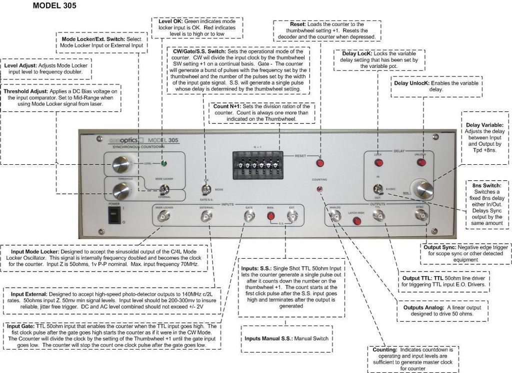
1 Model 305 Synchronous Countdown System Introduction: The Model 305 pre-settable countdown electronics is a high-speed synchronous divider that generates an electronic trigger pulse, locked in time with the input stimulus. The output trigger rate is integer related to the input clock rate by a six decade thumbwheel switch on the front panel. The primary application of this instrument is to provide all the required timing, delay, adjustments and output signals necessary to drive a variety of laser pulse selection modulation systems. Technical Overview: The countdown utilizes Emitter Coupled Logic (ECL) to insure minimal jitter and toggle rates in excess of 140MHz. This system will accept the sinusoidal output of the mode-locker oscillator or a detected analog of the optical pulse train exiting the laser as its input clock. The mode locker input is internally frequency doubled before it becomes the clock for the counter. The external input is 1/1. There are three basic operating modes for the counter, CW, Gated and Single Shot. The CW mode outputs a continuous string of pulses with the division rate set by the thumbwheel. The Gated mode outputs a burst of pulses, the rate of the number of pulses in the burst is set by the thumbwheel and the width or number of pulses within the burst is controlled by a TTL pulse applied to the gate input of the instrument. The Single Shot mode outputs a single pulse in response to the leading edge of a TTL signal applied to the S.S. input. This input enables the counter to generate a single output pulse after it has divided the clock by the thumbwheel setting. The output pulse is therefore delayed in time from the TTL Single Shot input by the setting of the thumbwheel and the input clock rate. The counter automatically resets itself after the pulse is generated. In all operating modes, the timing of the counter is tied only to the input clock, the external mode inputs (Gate or Single Shot) simply enable the event to occur. There are three outputs generated by the system, a High Speed Analog Output, TTL Output and a Line Sync Out. The High Speed Analog Output is a capable of operating up to 70MHz output rates. The TTL Out will deliver output rates in excess of 1MHz. The Line Sync is capable over the full range of the instrument. All outputs are designed to drive a 50ohm load. 1
2 The instrument has an 8ns variable delay along with a 8ns fixed (in/out) delay. The variable delay element is a 7-bit digital delay line with a linear front panel control. This delay feature yields a total of 16ns of adjustment with a minimum resolution of 62ps. The delay may be locked once the appropriate setting is obtained. Sixteen (16ns) of variable delay insures alignment of the electrical output of the instrument to the optical pulse down to C/2L rates of 63MHz. No further delay adjustments in the overall system are required. Model 305 Specifications: Input Clock Rate Countdown Range Input-Output Jitter Input Requirements Delay Outputs Mode Locker Input, 10MHz Min, 70MHz Max External Input, 10Hz min, 140MHz Max F(clock)/2 min, f(clock)/1*10^6 max <100ps, any count 1. Mode Locker Input sine wave, -6dbm min (112mv RMS), +15dbm,ax (1.3v RMS), Zi=50ohms 2. External Input 100mv peak min, 1.5ns min pulse width. +/- 2v peak max. Zi=50ohms 3. Gate Input = TTL levels, min width one clock period. Burst ends one count after negative edge of gate input signal. Zi=50ohms 4. Single Shot Input = TTL levels, 10ns min pulse width. Zi=50ohms. Variable 0-to-8ns, 7bit digital delay line. 62ps min resolution. Controlled by linear, single turn front panel control. Fixed 8ns Switch selectable on front panel (in/out) TTL 50 ohm line driver, Voh type 2.5v into 50ohm load. Pulse width 1us type (Pulse with is set internally by discrete components). Tr, Tf, <3ns type Analog Tr, Tf, <2ns, Unipolar 0-to-+1v fixed amplitude. Designed to drive DC coupled 50ohm load to ground. Pulse width 8ns, set internally by 50ohm coax delay line. Threshold Adjustment Input Power Dimensions Weight Sync 50ohm TTL line driver, 1.3v into 50ohms. Negative edge. +/- 200mv applied to input comparator via single turn front panel control VAC, 47-63Hz, 50W 133 H x 430 W x 343 D mm. Rack Mountable x x 13.5 Net 6.8 Kg, (15lbs) 2
3 Interface and Operating Instructions There are two types of operational modes the Model 305 will typically be used in. 1. Mode Locker Input. This mode takes a sample of the electrical signal generated by a Mode Locker Oscillator; frequency doubles it and translates the signal to ECL logic levels to drive the clock line of the counter. 2. External Input. This mode will typically be a detected analog of the optical pulse train exiting the laser. High speed PIN or avalanche photo-detectors would be used to convert the laser output to an electrical signal. This input is then directly converted to ECL to drive the clock line of the counter. Mode Locker Input: The Mode Locker input is designed to accept the electrical signal from the oscillator directly. Certain level requirements on this signal must be verified before the signal is connected to the instrument. The input level into a 50ohm load must be a minimum of -6dbm (112mv RMS) in amplitude and be between 10MHz and 70MHz. The input level may be greater than -6dbm but should be less than +15dbm (1.3v RMS) to avoid damage to the front end of the system. An external 50ohm attenuator should be used to reduce this level if required. Connect the Model Locker signal to the BNC connector marked Mode Locker. Place the Threshold control to mid-range and adjust the Level control to obtain a green indication on the level LED. Monitor the analog output on the oscilloscope terminated in 50ohms. Se the thumbwheel to 9, Mode Switch to CW connect the sync output to the horizontal time base of the oscilloscope. The signal on the oscilloscope should be 1/10 the C/2L mode space of the laser. Slow the scope sweep rate to allow 5-10 pulses to appear. The output signal should be jitter-free. Some adjustment of the level control and the threshold control may be required to obtain a jitter free signal. The level control adjusts the Mode Locker electrical input signal level to the frequency doubler. The frequency doubler is sensitive to the input amplitude. In order to obtain the best fundamental suppression, the level control should be adjusted for the best lock on the signal being viewed on the oscilloscope. The thumbwheel may be set to the desired division (+1), and the proper output be connected to the drive electronics. The analog output is designed to be used in low division applications. The TTL output for selection rates less than 1MHz. To align the optical gate created by the driver/modulator to the laser pulse, 3
4 adjust the variable delay control. This control provides a total of 8ns of adjustment. If more is required a fixed 8ns can be added to the variable setting by the fixed 8ns In/Out switch. External Input: This input may be used for a variety of input signals, most commonly the electrical signal generated by a high-speed photo-detector sampling the optical pulses directly. This input is DC coupled and care must be taken to prevent damage to the sensitive IC s that are common to this input. Note: Any signal connected to this input should be viewed on an oscilloscope to verify compliance with the input limits before actual connection is made to the instrument. Never exceed +/- 2V DC and AC Combined Typically, low level signals (hundreds of milli-volts) will be applied to this input. Photo-detectors that have been mistakenly biased in the forward direction can permanently damage the input comparator and termination. The external input requires 100mv peak-to-peak input to insure a jitter free trigger. Any typical DC offset and baseline ring may be accommodated by the threshold control. This control provides +/- 200mv DC offset to the input comparator. For example, if the detected signal were + 150mv peak with 20-30mv of damped ring on the baseline, the threshold control would typically be adjusted to mv to move the trip point of the comparator to a transient free zone. Follow the procedure as outline in the mode locker input to view the analog output. The threshold control should be adjusted for the best hard lock. The external input trips on the leading edge of the signal. This edge should be fast and clean to avoid jitter. 4
5 5
6 Controls and Indicators Mode Locker / External Switch: This switch selects either the Mode Locker input or the external input and directs the signal at their respective BNC connectors to the appropriate electronics on the Front-End PC board. The mode locker input is directed to an amplifier and peak detectors that allow the operator to adjust the level of the signal to the proper operating range. The External input is directed to the input comparator on the Front-End board directly. When the Mode Locker input is selected, the signal at the input is frequency doubled before it reaches the input comparator. The input comparator coverts either of the two inputs to ECL logic outputs to run the clock line of the counter. Level Control: This control adjusts the level of the signal at the Mode Locker input only. It is not in the circuit when the switch is in External. The level of the signal into the frequency doubler is controlled by this potentiometer. In order to minimize the fundamental output of the doubler, the level into it must be between certain limits. This control will allow the operator to either increase or decrease the signal from the Mode Locker oscillator to best reduce the fundamental feedthrough of the doubler. The control is adjusted properly when LEVEL LED is green and a jitter free output is obtained from the instrument. Threshold Control: This control adjusts the DC bias voltage on the un-driven input (-) of the input comparator. It is in the circuit for both Mode Locker inputs and External Inputs. When the system is being used with the Mode Locker input, this control should be set to mid-range (0v). This control provides a convenient method determining where the input comparator will trip on either the External or Mode Locker input signal. (See figure 1) 6
7 In figure 1, the input signal that the system is attempting to lock on has a number of areas where a double or false trigger might occur. At the baseline, ring generated by parasitic resonances in the detector electronics may trigger the counter several times for a single pulse. Also, on the leading edge of the signal, triggering at 60-70mv may generate jitter due to the input window of the comparator. The threshold adjustment allows the comparator s operating point to be optimized for the desired input signal. 7
8 CW/GATE/S.S. Mode Switch: This switch selects the appropriate operating mode for the counter. The CW mode requires no inputs other than the main clock input. It outputs a continuous string of pulse whose rate is determined by the setting of the thumbwheel switch and the input clock rate. The Gated mode requires an external TTL timing signal at the Gated input connector. The counter will start operating the first clock pulse after the positive going edge of the gate input signal and continue to run as in the CW mode for as long as this input is held high. The count will terminate one output count after the Gate input goes low. The Single Shot mode also requires an external timing signal. A TTL signal applied to the S.S. input allows the counter to generate a single output pulse at a rate determined by the S.S. source. The positive going edge of this TTL input enables the counter to divide the input clock rate by the setting of the thumbwheel. A single output pulse is generated when the count is reached and the counter resets itself to wait for the next positive edge of the S.S> input signal. This mode allows eternal control of the rate while the thumbwheel sets the incremental delay between the S.S. input and the output pulse. 8

9 9
10 10
11 Thumbwheel Switch: The thumbwheel loads the counter to the number selected on the six decade switch plus one (+1) count. The decoder automatically detects if a difference exists between the number on the thumbwheel and the binary input to the counter. If an error exists, the right count is loaded. When a change is made to the thumbwheel, the counter is inhibited until the new number is loaded. Reset Push Button: Simply resets the decoder to the number present on the thumbwheel. Counting LED: This indicator is illuminated when the counter is running. The drive for this function is obtained at the output end of the countdown/delay chain. It will operate only if pulses are being delivered to the output drivers. This indicator provides a convenient means of determining if the input clock to the system is of sufficient amplitude and pulse width to operate the clock line of the counter. Delay Controls: The variable delay knob controls the setting of a 7bit digital delay line. It has a range of 0 to >8ns in 62ps steps. This feature adds delay to the intrinsic propagation delay of the counter and its output stages. The LOCK and UNLOCK illuminated pushbuttons simply latch or unlatch the binary setting into the delay chips. When the delay is locked, any jitter that might be generated by the LSB s of the 7bit work are latched. The fixed 8ns IN/OUT delay provides a greater total delay range. This delay is added before the output sync signal picked off to reduce the overall delay between sync and output. 11
12 Inputs and Outputs Inputs: Mode Locker input is designed to accept the sinusoidal output of the mode locker oscillator, frequency double it and convert it to ECL logic levels to drive the clock line of the counter. An adjustment control is provided (level) to bring the oscillator signal with the desired limits of the frequency doubler. In order to minimize the fundamental (F) feed through of the doubler (2F), the level into it must be between certain limits. Excessive Fundamental feed through will place AM modulation on the doubled output and may cause the input comparator to generate some jitter on the clock line. By frequency doubling this input, correlation between the selected setting of the thumbwheel and the output rate of the counter is maintained. Input amplitude of the mode locker signal should be between -6dbm and +15dbm for proper operation. This input is DC coupled to the 50ohm termination, any DC terms in the output of the mode locker oscillator should be removed before connection is made to the instrument. External: The External input provides a direct path to the non-inverting input of the input comparator. This input is DC coupled to the 50ohm termination and the (+) input of the comparator. The comparator has a 30mv window (uncertainty) between its inverting and non-inverting inputs. This device is capable of operating well over 500MHz and will trip on transients in the input waveform if care is not taken to insure the input signal is free of undesirable responses. The inverting (-) terminal of the comparator is controlled by the threshold control, providing DC bias voltage to the device. This bias voltage allows the 30mv window of the comparator to be moved to a position on the input waveform most desirable for triggering the clock line of the counter. This input will accept a positive or negative going signal but the clock is always generated by the positive going edge the waveform. The mode locker oscillator signal may be applied to this input if desired. Care should be exercised at this input to insure combined DC and AC signals do not exceed +/- 2v about ground. Pulse width of the input signal at the trip point should be in the order of 1-to-1.5ns for proper clocking of the counter. Gate: This input accepts TTL levels and is terminated in 50ohms to ground.. If this input is to be driven from TTL logic, a 74S140 50ohm line driver is recommended. Single Shot: Same as input levels of Gate (see above). 12
13 Single Shot Pushbutton: This manual input is wired with the BNC single shot in and has its own internal one shot pulse generator. Analog Output: This output is designed to drive high frequency linear RF Power Amplifiers. The ECL signal at the end of the countdown and the delay chain is level shifted and amplified slightly to provide a unipolar 0 to +1v pulse out into a 50ohm DC load to ground. The pulse width of this signal is determined by a length of 50ohm coax used as a delay line in a D type flip-flop after the delay chips. The width of this pulse may be altered by either increasing or decreasing the length of this line. The pulse width will be fixed by this delay element so high output rates (low division) may not be attainable if the pulse width is made too long. With the standard 8ns width, the analog out will run to the limit of the instrument (140MHz/2). Rise and Fall times are in the order of 2ns. TTL: This output is a 50hm TTL line driver designed to drive avalanche or HV Mosfet type drivers with 50ohm input impedance. The output pulse width of this signal is set internally by discrete components and is in the order of 800ns. The pulse width may be altered by changing these components down to a minimum of approximately 50ns. If the countdown rate is such that the output signal is in excess of 1MHz, the output will stay logic high. Sync: This output is intended to be used for oscilloscope horizontal time base trigger. The source for this output is the countdown signal before the variable delay line and after the fixed delay (if selected). The negative edge of the signal should be used for sync as the positive going edge will be delayed in time as a function of the clock input rate. This output will deliver 1.2v into an open circuit,.6v if the sync line is terminated in 50ohms at the oscilloscope. 13
Model 310H Fast 800V Pulse Generator
 KEY FEATURES Temperature Stability +/-5ppm 100 V to 800 V into 50 Ω
Model 25D Manual. Introduction: Technical Overview:
 Model 25D Manual Introduction: The Model 25D drive electronics is a high voltage push-pull power amplifier capable of output voltage swings in the order of 175v P-P, push-pull. The Model 25D provides output
GFT Channel Digital Delay Generator
 Features 20 independent delay Channels 100 ps resolution 25 ps rms jitter 10 second range Output pulse up to 6 V/50 Ω Independent trigger for every channel Four triggers Three are repetitive from three
GFT1504 4/8/10 channel Delay Generator
 Features 4 independent Delay Channels (10 in option) 100 ps resolution (1ps in option) 25 ps RMS jitter (channel to channel) 10 second range Channel Output pulse 6 V/50 Ω, 3 ns rise time Independent control
Experiment 1: Instrument Familiarization (8/28/06)
") Electrical Measurement Issues Experiment 1: Instrument Familiarization (8/28/06) Electrical measurements are only as meaningful as the quality of the measurement techniques and the instrumentation applied
Electrical Measurement Issues Experiment 1: Instrument Familiarization (8/28/06) Electrical measurements are only as meaningful as the quality of the measurement techniques and the instrumentation applied
OPERATING MANUAL CAVITY DUMPER / PULSE PICKER DRIVER MODEL NUMBER: 643ZZ.ZZZ-SYN-Y-X
 OPERATING MANUAL CAVITY DUMPER / PULSE PICKER DRIVER MODEL NUMBER: Where: X is the division factors for the pulse rate. Y is the multiplier of the reference input frequency 3ZZ.ZZZ is the output RF frequency
MODEL 25D MANUAL PRODUCT OVERVIEW:
 MODEL 25D MANUAL PRODUCT OVERVIEW: The Model 25D drive electronics is a high voltage push-pull power amplifier capable of output voltage swings in the order of 175v P-P, push-pull. The Model 25D provides
Experiment 1: Instrument Familiarization
 Electrical Measurement Issues Experiment 1: Instrument Familiarization Electrical measurements are only as meaningful as the quality of the measurement techniques and the instrumentation applied to the
Model 25A Manual. Introduction:
 Model 25A Manual Introduction: The Model 25A drive electronics is a high voltage push-pull linear power amplifier capable of output voltage swings in the order of 145v P-P, push-pull. The Model 25A provides
TOE 7704 to TOE 7711 A
 Synthesizers/function generators with sweep, trigger, AM and frequency counter Special features 1 mhz to 44 MHz Sweep, trigger, gate Variable symmetry Digital display of frequency, sweep, AC, DC Amplitude
Dual Channel Function/Arbitrary Waveform Generators 4050B Series
 Data Sheet Dual Channel Function/Arbitrary Waveform Generators The Dual Channel Function/ Arbitrary Waveform Generators are capable of generating stable and precise sine, square, triangle, pulse, and arbitrary
OPERATING MANUAL DIGITALLY CONTROLLED FREQUENCY SYNTHESIZED OSCILLATOR MODEL NUMBER: ADSDFS-A DOCUMENT NUMBER: 51A19937C
 OPERATING MANUAL DIGITALLY CONTROLLED FREQUENCY SYNTHESIZED OSCILLATOR MODEL NUMBER: DOCUMENT NUMBER: 51A19937C For More Information, Contact: sales@goochandhousego.com www.goochandhousego.com As part
Model 865 RF / Ultra Low Noise Microwave Signal Generator
 Model 865 RF / Ultra Low Noise Microwave Signal Generator Features Excellent signal purity: ultra-low phase noise and low spurious Combination of highest output power and fastest switching Powerful touch-display
M302RM OPERATING MANUAL
 M302RM OPERATING MANUAL The Model 302RM is a Linear, high voltage, differential amplifier designed to drive a capacitive load such as Conoptics 350, 360, 370 series E.O. modulators. The amplifier is DC
R & D Electronics DIGITAL IC TRAINER. Model : DE-150. Feature: Object: Specification:
 DIGITAL IC TRAINER Model : DE-150 Object: To Study the Operation of Digital Logic ICs TTL and CMOS. To Study the All Gates, Flip-Flops, Counters etc. To Study the both the basic and advance digital electronics
Agilent 81133A/81134A
 Agilent 81133A/81134A Performance Verification Rev. 2.3, Dec. 2009 Agilent Technologies Introduction Use these tests if you want to check that the Agilent 81133A / 81134A Pulse / Pattern Generator is
Digital Applications of the Operational Amplifier
 Lab Procedure 1. Objective This project will show the versatile operation of an operational amplifier in a voltage comparator (Schmitt Trigger) circuit and a sample and hold circuit. 2. Components Qty
CONVERTING 1524 SWITCHING POWER SUPPLY DESIGNS TO THE SG1524B
 LINEAR INTEGRATED CIRCUITS PS-5 CONVERTING 1524 SWITCHING POWER SUPPLY DESIGNS TO THE SG1524B Stan Dendinger Manager, Advanced Product Development Silicon General, Inc. INTRODUCTION Many power control
ericssonz LBI-38640E MAINTENANCE MANUAL FOR VHF TRANSMITTER SYNTHESIZER MODULE 19D902780G1 DESCRIPTION
 MAINTENANCE MANUAL FOR VHF TRANSMITTER SYNTHESIZER MODULE 19D902780G1 TABLE OF CONTENTS Page DESCRIPTION........................................... Front Cover GENERAL SPECIFICATIONS...................................
ELECTRONICS FOR PULSE PICKERS
 Rev. 3.07 / 2014 04 10 ELECTRONICS FOR PULSE PICKERS TABLE OF CONTENTS Description... 2 High voltage switches... 3 Appearance / dimensions... 3 Power ratings... 3 Interfaces... 4 Specifications... 6 How
What the LSA1000 Does and How
 2 About the LSA1000 What the LSA1000 Does and How The LSA1000 is an ideal instrument for capturing, digitizing and analyzing high-speed electronic signals. Moreover, it has been optimized for system-integration
Agilent 8360B Series Synthesized Swept Signal Generators 8360L Series Synthesized Swept CW Generators Data Sheet
 Agilent 8360B Series Synthesized Swept Signal Generators 8360L Series Synthesized Swept CW Generators Data Sheet 10 MHz to 110 GHz Specifications apply after full user calibration, and in coupled attenuator
Getting Started. MSO/DPO Series Oscilloscopes. Basic Concepts
 Getting Started MSO/DPO Series Oscilloscopes Basic Concepts 001-1523-00 Getting Started 1.1 Getting Started What is an oscilloscope? An oscilloscope is a device that draws a graph of an electrical signal.
Exam Booklet. Pulse Circuits
 Exam Booklet Pulse Circuits Pulse Circuits STUDY ASSIGNMENT This booklet contains two examinations for the six lessons entitled Pulse Circuits. The material is intended to provide the last training sought
PN9000 PULSED CARRIER MEASUREMENTS
 The specialist of Phase noise Measurements PN9000 PULSED CARRIER MEASUREMENTS Carrier frequency: 2.7 GHz - PRF: 5 khz Duty cycle: 1% Page 1 / 12 Introduction When measuring a pulse modulated signal the
Basic Logic Circuits
 Basic Logic Circuits Required knowledge Measurement of static characteristics of nonlinear circuits. Measurement of current consumption. Measurement of dynamic properties of electrical circuits. Definitions
Analog Arts SF990 SF880 SF830 Product Specifications
 1 www.analogarts.com Analog Arts SF990 SF880 SF830 Product Specifications Analog Arts reserves the right to change, modify, add or delete portions of any one of its specifications at any time, without
Synthesized Function Generators DS MHz function and arbitrary waveform generator
 Synthesized Function Generators DS345 30 MHz function and arbitrary waveform generator DS345 Function/Arb Generator 1 µhz to 30.2 MHz frequency range 1 µhz frequency resolution Sine, square, ramp, triangle
Analog Arts SL987 SL957 SL937 SL917 Product Specifications [1]
![Analog Arts SL987 SL957 SL937 SL917 Product Specifications [1]](/thumbs/95/126095980.jpg "Analog Arts SL987 SL957 SL937 SL917 Product Specifications [1]") www.analogarts.com Analog Arts SL987 SL957 SL937 SL917 Product Specifications [1] 1. These models include: an oscilloscope, a spectrum analyzer, a data recorder, a frequency & phase meter, an arbitrary
www.analogarts.com Analog Arts SL987 SL957 SL937 SL917 Product Specifications [1] 1. These models include: an oscilloscope, a spectrum analyzer, a data recorder, a frequency & phase meter, an arbitrary
9200 Series, 300 MHz Programmable Pulse Generator
 9200 Series, 300 MHz Programmable Pulse Generator Main Features Variable edge pulses (1 nsec to 1 msec) at rates to 250 MHz Fast 300 psec edges to 300 MHz Wide output swings to 32 V at pulse rates to 50
Model 745 Series. Berkeley Nucleonics Test, Measurement and Nuclear Instrumentation since Model 845-HP Datasheet BNC
 Model 845-HP Datasheet Model 745 Series Portable 20+ GHz Microwave Signal Generator High Power +23dBM Power Output 250 fs Digital Delay Generator BNC Berkeley Nucleonics Test, Measurement and Nuclear Instrumentation
FFP-C Fiber Fabry-Perot Controller OPERATING INSTRUCTIONS. Version 1.0 MICRON OPTICS, INC.
 FFP-C Fiber Fabry-Perot Controller OPERATING INSTRUCTIONS Version 1.0 MICRON OPTICS, INC. 1852 Century Place NE Atlanta, GA 30345 USA Tel (404) 325-0005 Fax (404) 325-4082 www.micronoptics.com Page 2 Table
This section lists the specications for the Agilent 8360 B-Series. generators, Agilent Technologies has made changes to this product
 2c Specifications This section lists the specications for the Agilent 8360 B-Series swept signal generator. In a eort to improve these swept signal generators, Agilent Technologies has made changes to
Models 296 and 295 combine sophisticated
 Established 1981 Advanced Test Equipment Rentals www.atecorp.com 800-404-ATEC (2832) Models 296 and 295 50 MS/s Synthesized Multichannel Arbitrary Waveform Generators Up to 4 Independent Channels 10 Standard
GBT. LO Reference Distribution System. Maintenance Manual. M. J. Stennes September 15, 2004
 GBT LO Reference Distribution System Maintenance Manual M. J. Stennes September 15, 2004 Table of Contents i. Abstract.. 2 I. System Description.. 3 II Maintenance Procedures.. 7 (a) Cable length adjustments
Thornwood Drive Operating Manual: Two-SCR General Purpose Gate Firing Board FCRO2100 Revision H
 http://www.enerpro-inc.com info@enerpro-inc.com 5780 Thornwood Drive Report R188 Goleta, California 93117 February 2011 Operating Manual: Two-SCR General Purpose Gate Firing Board FCRO2100 Revision H Introduction
Arbitrary/Function Waveform Generators 4075B Series
 Data Sheet Arbitrary/Function Waveform Generators Point-by-Point Signal Integrity The Arbitrary/Function Waveform Generators are versatile high-performance single- and dual-channel arbitrary waveform generators
BNC Model 6040 Pulse Generator Specifications
 Hom SAM - Portabl Nuclear Detectio Surveillance an Measurement, Gamm Spectroscopy, Radiatio Monitors, Complete MCA Signal Generator Digital Delay Generators General Purpose Puls Generators, Light Pulse
PAiA 4780 Twelve Stage Analog Sequencer Design Analysis Originally published 1974
 PAiA 4780 Twelve Stage Analog Sequencer Design Analysis Originally published 1974 DESIGN ANALYSIS: CLOCK As is shown in the block diagram of the sequencer (fig. 1) and the schematic (fig. 2), the clock
Digital Fundamentals 8/25/2016. Summary. Summary. Floyd. Chapter 1. Analog Quantities
 8/25/206 Digital Fundamentals Tenth Edition Floyd Chapter Analog Quantities Most natural quantities that we see are analog and vary continuously. Analog systems can generally handle higher power than digital
UMAINE ECE Morse Code ROM and Transmitter at ISM Band Frequency
 UMAINE ECE Morse Code ROM and Transmitter at ISM Band Frequency Jamie E. Reinhold December 15, 2011 Abstract The design, simulation and layout of a UMAINE ECE Morse code Read Only Memory and transmitter
BE1-81O/U DIGITAL FREQUENCY RELAY FEATURES
 BE1-81O/U DIGITAL FREQUENCY RELAY The BE1-81O/U Digital Frequency Relay senses an ac voltage from a power system or generator to provide protection in the event that the frequency exceeds predetermined
Model 3102D 0-2 kv H.V. Power Supply
 Features Compact single width NIM package Regulated up to ±2000 V dc. 1 ma output Noise and ripple 3 mv peak to peak Overload and short circuit protected Overload, inhibit and polarity status indicators
Lab 9 RF Wireless Communications
 Lab 9 RF Wireless Communications Figure 9.0. Guglielmo Marconi Midday at Signal Hill near St. John s, Newfoundland, in Canada, Guglielmo Marconi pressed his ear to a telephone headset connected to an experimental
TG1010A AIM & THURLBY THANDAR INSTRUMENTS. 10MHz programmable DDS function generator. Direct Digital Synthesis
 AIM & THURLBY THANDAR INSTRUMENTS TG1010A 10MHz programmable DDS function generator Arbitrary Waveform Capability, Extensive Modulation Modes Direct Digital Synthesis All the versatility of a function
SG1524/SG2524/SG3524 REGULATING PULSE WIDTH MODULATOR DESCRIPTION FEATURES HIGH RELIABILITY FEATURES - SG1524 BLOCK DIAGRAM
 SG54/SG54/SG54 REGULATING PULSE WIDTH MODULATOR DESCRIPTION This monolithic integrated circuit contains all the control circuitry for a regulating power supply inverter or switching regulator. Included
RF Signal Generators. SG380 Series DC to 2 GHz, 4 GHz and 6 GHz analog signal generators. SG380 Series RF Signal Generators
 RF Signal Generators SG380 Series DC to 2 GHz, 4 GHz and 6 GHz analog signal generators SG380 Series RF Signal Generators DC to 2 GHz, 4 GHz or 6 GHz 1 µhz resolution AM, FM, ΦM, PM and sweeps OCXO timebase
Model 25D Manual. Introduction:
 Model 5D Manual Introduction: The Model 5D drive electronics is a high voltage push-pull power amplifier capable of output voltage swings in the order of 75v P-P, push-pull. The Model 5D provides output
The University of Jordan Mechatronics Engineering Department Electronics Lab.( ) Experiment 1: Lab Equipment Familiarization
 Experiment 1: Lab Equipment Familiarization") The University of Jordan Mechatronics Engineering Department Electronics Lab.(0908322) Experiment 1: Lab Equipment Familiarization Objectives To be familiar with the main blocks of the oscilloscope and
The University of Jordan Mechatronics Engineering Department Electronics Lab.(0908322) Experiment 1: Lab Equipment Familiarization Objectives To be familiar with the main blocks of the oscilloscope and
Sequential Logic Circuits
 Exercise 2 Sequential Logic Circuits 1 - Introduction Goal of the exercise The goals of this exercise are: - verify the behavior of simple sequential logic circuits; - measure the dynamic parameters of
HESP-E-AO-PS Laboratory Diode Driver (For use with Kigre AO-1010 and AO-610 lasers)
") HESP-E-AO-PS Laboratory Diode Driver (For use with Kigre AO-1010 and AO-610 lasers) Kigre manufactures a laboratory laser diode driver for use with the AO-1010 and AO-610 actively Q-switched laser heads.
HESP-E-AO-PS Laboratory Diode Driver (For use with Kigre AO-1010 and AO-610 lasers) Kigre manufactures a laboratory laser diode driver for use with the AO-1010 and AO-610 actively Q-switched laser heads.
Model 765 Fast Rise Time Pulse Generator
 Fast Rise Time Pulse Generator Features of the 765: 70 ps Rise (Tr) and Fall (Tf) Times +/- 5.0 Volts pk-pk Delay and Width Resolution of 10 ps Narrow Widths (300 ps) Jitter < 25 ps Complete Channel Multiplex
EXPERIMENT 12: DIGITAL LOGIC CIRCUITS
 EXPERIMENT 12: DIGITAL LOGIC CIRCUITS The purpose of this experiment is to gain some experience in the use of digital logic circuits. These circuits are used extensively in computers and all types of electronic
RIGOL Data Sheet. DG3000 Series Function/Arbitrary Waveform Generator DG3121A, DG3101A, DG3061A. Product Overview. Easy to Use Design.
 RIGOL Data Sheet DG3000 Series Function/Arbitrary Waveform Generator DG3121A, DG3101A, DG3061A Product Overview DG3000 Series Function/Arbitrary Waveform Generators adopt DDS technology, which enables
MQH0XX-YYDS3-ZZZ-2S. High Power 2 Channel RF Driver: For 2 Acousto-optic Q-Switches. Description: Key Features: Applications:
 High Power 2 Channel RF Driver: For 2 Acousto-optic Q-Switches MQH0XX-YYDS3-ZZZ-2S Former Model Number: 390XX-YYDSZZZ-2CH-A Description: The MQH0XX-YYDS3-ZZZ-2S is a High Power RF Driver with two RF outputs
B MTS Systems Corp., Model Function Generator
 0189 115585-02 B MTS Systems Corp., 1988 Model 410.81 Function Generator Table of Contents Section 1 Introduction 1.1 Functional Description 1-1 1.2 Specifications 1-2 Section 2 Operation 2.1 Control Mode
B.E. SEMESTER III (ELECTRICAL) SUBJECT CODE: X30902 Subject Name: Analog & Digital Electronics
 SUBJECT CODE: X30902 Subject Name: Analog & Digital Electronics") B.E. SEMESTER III (ELECTRICAL) SUBJECT CODE: X30902 Subject Name: Analog & Digital Electronics Sr. No. Date TITLE To From Marks Sign 1 To verify the application of op-amp as an Inverting Amplifier 2 To
B.E. SEMESTER III (ELECTRICAL) SUBJECT CODE: X30902 Subject Name: Analog & Digital Electronics Sr. No. Date TITLE To From Marks Sign 1 To verify the application of op-amp as an Inverting Amplifier 2 To
SRVODRV REV7 INSTALLATION NOTES
 SRVODRV-8020 -REV7 INSTALLATION NOTES Thank you for purchasing the SRVODRV -8020 drive. The SRVODRV -8020 DC servo drive is warranted to be free of manufacturing defects for 1 year from the date of purchase.
TAPR TICC Timestamping Counter Operation Manual. Introduction
 TAPR TICC Timestamping Counter Operation Manual Revised: 23 November 2016 2016 Tucson Amateur Packet Radio Corporation Introduction The TAPR TICC is a two-channel timestamping counter ("TSC") implemented
CIRCUIT-TEST ELECTRONICS
 USER'S MANUAL Sweep Function Generator with Counter SWF-8030 CIRCUIT-TEST ELECTRONICS www.circuittest.com TABLE OF CONTENTS SAFETY INFORMATION...page 3 INTRODUCTION... 4 SPECIFICATIONS... 5 FRONT PANEL
Why Modern Servicing Requires Complete Waveform & Circuit Analyzing!
 Why Modern Servicing Requires Complete Waveform & Circuit Analyzing! DC Bias Voltages DC Currents Resistance AC Signals Of Various Waveshapes & Amplitudes Continuity Of Circuit Paths & Components If you
High Current MOSFET Toggle Switch with Debounced Push Button
 Set/Reset Flip Flop This is an example of a set/reset flip flop using discrete components. When power is applied, only one of the transistors will conduct causing the other to remain off. The conducting
Output Impedance. Duty Cycle Range. Buffer Size Resolution. PROTECTION Input Over Voltage. Output Short Circuit. TRIGGERING Sources.
 3 Channel Digital Storage Oscilloscope (DSO) Instrument VERTICAL SPECIFICATIONS Analogue Bandwidth (-3dB) Bandwidth Limiting Rise time (10% to 90%, calculated) Input ranges (full scale) Input sensitivity
IES Digital Mock Test
 . The circuit given below work as IES Digital Mock Test - 4 Logic A B C x y z (a) Binary to Gray code converter (c) Binary to ECESS- converter (b) Gray code to Binary converter (d) ECESS- To Gray code
1 Second Time Base From Crystal Oscillator
 1 Second Time Base From Crystal Oscillator The schematic below illustrates dividing a crystal oscillator signal by the crystal frequency to obtain an accurate (0.01%) 1 second time base. Two cascaded 12
Racal Instruments. Product Information
 Racal Instruments 3172 200 MS/s Waveform Generator & Dual 50 MHz Pulse/ Timing Generator The, a 200 MS/s Waveform Generator and Dual 50 MHz Pulse and Timing Generator, combines multi-instrument density
HIGH LOW Astable multivibrators HIGH LOW 1:1
 1. Multivibrators A multivibrator circuit oscillates between a HIGH state and a LOW state producing a continuous output. Astable multivibrators generally have an even 50% duty cycle, that is that 50% of
Electricity and Electronics Constructor Kits
 EEC470 Series The Electricity and Electronics Constructor EEC470 series is a structured practical training programme comprising an unpowered construction deck (EEC470) and a set of educational kits. Each
Dual Channel Function/Arbitrary Waveform Generators 4050 Series
 Data Sheet Dual Channel Function/Arbitrary Waveform Generators The Dual Channel Function/Arbitrary Waveform Generators are capable of generating stable and precise sine, square, triangle, pulse, and arbitrary
1 sur 8 07/04/ :06
 1 sur 8 07/04/2012 12:06 Les Banki Circuit Updated Version August 16, 2007 Synchronized 3 Frequency PWM circuit & cell drivers (for resonance electrolysis of water) Background The basic idea for this design
MULT SWP X1K K VERN START FREQ DURATION AMPLITUDE 0 TTL OUT RAMP
 Signal Generators This document is a quick reference guide to the operation of the signal generators available in the laboratories. Major functions will be covered, but some features such as their sweep
MODEL745 FOUR CHANNEL DIGITAL DELAY/ PULSE GENERATOR
 MODEL745 FOUR CHANNEL DIGITAL DELAY/ PULSE GENERATOR Four delay and width channels 250 fs delay resolution Jitter as low as 5 ps rms for internally-triggered delays Jitter as low as 25ps rms for externally-triggered
Current Mode PWM Controller
 application INFO available UC1842/3/4/5 Current Mode PWM Controller FEATURES Optimized For Off-line And DC To DC Converters Low Start Up Current (
ELM409 Versatile Debounce Circuit
 ersatile Debounce Circuit Description The ELM is digital filter circuit that is used to interface mechanical contacts to electronic circuits. All mechanical contacts, whether from switches, relays, etc.
AC LAB ECE-D ecestudy.wordpress.com
 PART B EXPERIMENT NO: 1 AIM: PULSE AMPLITUDE MODULATION (PAM) & DEMODULATION DATE: To study Pulse Amplitude modulation and demodulation process with relevant waveforms. APPARATUS: 1. Pulse amplitude modulation
CHAPTER 6. Motor Driver
 CHAPTER 6 Motor Driver In this lab, we will construct the circuitry that your robot uses to drive its motors. However, before testing the motor circuit we will begin by making sure that you are able to
CHAPTER 6 PHASE LOCKED LOOP ARCHITECTURE FOR ADC
 138 CHAPTER 6 PHASE LOCKED LOOP ARCHITECTURE FOR ADC 6.1 INTRODUCTION The Clock generator is a circuit that produces the timing or the clock signal for the operation in sequential circuits. The circuit
icwaves Inspector Data Sheet
 Inspector Data Sheet icwaves Advanced pattern-based triggering device for generating time independent pulses to avoid jitter and time-related countermeasures in SCA or FI testing. Riscure icwaves 1/9 Introduction
ML4818 Phase Modulation/Soft Switching Controller
 Phase Modulation/Soft Switching Controller www.fairchildsemi.com Features Full bridge phase modulation zero voltage switching circuit with programmable ZV transition times Constant frequency operation
5MHz FUNCTION GENERATOR
 5MHz FUNCTION GENERATOR MODEL GF-8056 User s Manual Elenco TM Electronics, Inc. Copyright 2004 by Elenco TM Electronics, Inc. All rights reserved. 753117 No part of this book shall be reproduced by any
AWG-GS bit 2.5GS/s Arbitrary Waveform Generator
 KEY FEATURES 2.5 GS/s Real Time Sample Rate 14-bit resolution 2 Channels Long Memory: 64 MS/Channel Direct DAC Out - DC Coupled: 1.6 Vpp Differential / 0.8 Vpp > 1GHz Bandwidth RF Amp Out AC coupled -10
ArbStudio Arbitrary Waveform Generators
 ArbStudio Arbitrary Waveform Generators Key Features Outstanding performance with 16-bit, 1 GS/s sample rate and 2 Mpts/Ch 2 and 4 channel models Digital pattern generator PWM mode Sweep and burst modes
Lab Manual Rev 2. General Information: Lab Report Format: EE360, Fall03, Kolk
 Lab Manual Rev 2 EE360, Fall03, Kolk General Information: 1. The lab is located in Dana 115. Our lab assistant is Jun Kondo. Lab hours for EE360 are Monday evenings 7:00 9:00 pm. The lab is available after
5MHz FUNCTION GENERATOR
 5MHz FUNCTION GENERATOR MODEL GF-8056 99 Washington Street Melrose, MA 02176 Phone 781-665-1400 Toll Free 1-800-517-8431 Visit us at www.testequipmentdepot.com User s Manual Elenco TM Electronics, Inc.
OPERATING INSTRUCTIONS AND SYSTEM DESCRIPTION FOR THE. ISO-STIM 01D STIMULUS ISOLATION UNIT ±100 V / ±10 ma, bipolar output
 OPERATING INSTRUCTIONS AND SYSTEM DESCRIPTION FOR THE ISO-STIM 01D STIMULUS ISOLATION UNIT ±100 V / ±10 ma, bipolar output VERSION 4.0 npi 2014 npi electronic GmbH, Bauhofring 16, D-71732 Tamm, Germany
GFT bit High Speed Digitizer
 FEATURES Up to 4 analog channels in only 1U space Up to 2GS/s sampling rate per channel 14 bits vertical resolution DC coupled with up to 1GHz bandwidth Programmable DC offset Internal and external clock
CD22202, CD DTMF Receivers/Generators. 5V Low Power DTMF Receiver. Features. Description. Ordering Information. Pinout. Functional Diagram
 SEMICONDUCTOR DTMF Receivers/Generators CD0, CD0 January 1997 5V Low Power DTMF Receiver Features Description Central Office Quality No Front End Band Splitting Filters Required Single, Low Tolerance,
Dual Channel Function/Arbitrary Waveform Generators 4050 Series
 Data Sheet Dual Channel Function/Arbitrary Waveform Generators The Dual Channel Function/Arbitrary Waveform Generators are capable of generating stable and precise sine, square, triangle, pulse, and arbitrary
PC-OSCILLOSCOPE PCS500. Analog and digital circuit sections. Description of the operation
 PC-OSCILLOSCOPE PCS500 Analog and digital circuit sections Description of the operation Operation of the analog section This description concerns only channel 1 (CH1) input stages. The operation of CH2
ModBox - Spectral Broadening Unit
 ModBox - Spectral Broadening Unit The ModBox Family The ModBox systems are a family of turnkey optical transmitters and external modulation benchtop units for digital and analog transmission, pulsed and
Current Mode PWM Controller
 Current Mode PWM Controller UC1842/3/4/5 FEATURES Optimized For Off-line And DC To DC Converters Low Start Up Current (
Keysight Technologies N9320B RF Spectrum Analyzer
 Keysight Technologies N9320B RF Spectrum Analyzer 9 khz to 3.0 GHz Data Sheet Definitions and Conditions The spectrum analyzer will meet its specifications when: It is within its calibration cycle It has
LAB I. INTRODUCTION TO LAB EQUIPMENT
 1. OBJECTIVE LAB I. INTRODUCTION TO LAB EQUIPMENT In this lab you will learn how to properly operate the oscilloscope Agilent MSO6032A, the Keithley Source Measure Unit (SMU) 2430, the function generator
4 K to 512 K words (2 n, n = 12 to 19) or 2 to 10,000 control points (linear interpolation between control points)
 or 2 to 10,000 control points (linear interpolation between control points)") The values of items marked with *1 are guaranteed values. All other values are either nominal values or typical (typ.) values, and are not guaranteed. Conditions unless otherwise mentioned are as follows:
The values of items marked with *1 are guaranteed values. All other values are either nominal values or typical (typ.) values, and are not guaranteed. Conditions unless otherwise mentioned are as follows:
Agilent N9320B RF Spectrum Analyzer
 Agilent N9320B RF Spectrum Analyzer 9 khz to 3.0 GHz Data Sheet Definitions and Conditions The spectrum analyzer will meet its specifications when: It is within its calibration cycle It has been turned
P a g e 1 ST985. TDR Cable Analyzer Instruction Manual. Analog Arts Inc.
 P a g e 1 ST985 TDR Cable Analyzer Instruction Manual Analog Arts Inc. www.analogarts.com P a g e 2 Contents Software Installation... 4 Specifications... 4 Handling Precautions... 4 Operation Instruction...
Model 855 RF / Microwave Signal Generator
 Features Very low phase noise Fast switching Phase coherent switching option 2 to 8 phase coherent outputs USB, LAN, GPIB interfaces Applications Radar simulation Quantum computing High volume automated
High Speed PWM Controller
 High Speed PWM Controller application INFO available FEATURES Compatible with Voltage or Current Mode Topologies Practical Operation Switching Frequencies to 1MHz 50ns Propagation Delay to Output High
Chapter 10 Adaptive Delta Demodulator
 Chapter 10 Adaptive Delta Demodulator 10-1 Curriculum Objective 1. To understand the operation theory of adaptive delta demodulation. 2. To understand the signal waveforms of ADM demodulation. 3. Design
Digital Fundamentals
 Digital Fundamentals Tenth Edition Floyd Chapter 1 2009 Pearson Education, Upper 2008 Pearson Saddle River, Education NJ 07458. All Rights Reserved Objectives After completing this unit, you should be