Optimum elevation gain and zero radiation at 90 degrees can be achieved with
|
|
|
- Douglas Houston
- 5 years ago
- Views:
Transcription


1

2 Question John FM Antennas: One way to reduce downward RF signal near the tower is to use short -spaced element antennas. Is there another way it can be accomplished? 2


3 Optimum elevation gain and zero radiation at 90 degrees can be achieved with The nulls in an elevation pattern are defined by: A null at 90 degrees will eliminate downward radiation 1 k k 90 sin or 1 nd nd sin 1 k nd k d n k n Null angle Integer Element spacing Number of elements Wavelength d = n 1 n k d n For k=1,2,3.. k n, 2n, 3n n 2 n 1 n 1 n 2 d...,,,... n n n n Where n 1 n will be the most aperture efficient spacing 3
/n approaches the")

4 (n-1)/n is much more efficient than ½ wave spacing (n-1)/n approaches the efficiency of a full wave spaced array as n increases, but has no downward radiation 4


5 Or..Increase the height of the antenna s uw/cm 2 = 33.4 F2 ERP r 2 F = field strength ERP in Watts r = distance in meters Double the height and reduce the signal strength 4X (6 db) 5
6 Question What special considerations are there for Channel 14? Looking forward to it! Dan 6
7 Noise power from high power transmitter can degrade land mobile radio SNR in the MHz band Required additional attenuation for each land mobile channel 7
8 C h a n n e l 1 4 Step 1: Get a consultants Study: -catalogs nearby land mobile receivers - calculates required filter attenuation Courtesy DuTreil, Lundin & Rackley 8
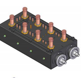
9 Design filter to meet requirement typically 12 pole Note: solid state Tx shoulder values <<- 40 db can simplify filter design 9
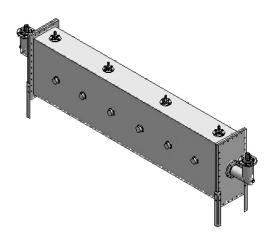
10 Up to 20 kw reflective 12 pole 143 x 24 x 24 (363 cm x 61cm x 61cm) Up to 40 kw CIF 12 pole 143 x 48 x 36 (363 cm x 112 cm x 91 cm) 10
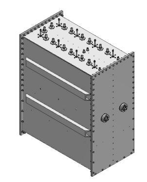
11 Up to 60 kw CIF 12 pole blowers - w/g hybrids 146 x 48 x 84 (371 cm x 122 cm x 213 cm) 11

12 Use 14 pole or add notches 12
13 Use of V-Pol may be limited if H/V discrimination built into land mobile rejection calculation Lower band edge roll-off (-2.92 MHz) forces either carrier reduction or frequency offset 13
14 Question The other guys claim end fed antennas are a better choice over center fed antennas. Why? John 14
15 The truth is Not a choice of preference Dictated by technical limitations and decisions Need both end fed and center fed in the product portfolio 15


16 Mechanically convenient to feed top mount antennas from the bottom RCA introduced the J type pylon in 1966 Triax technology Historically highlighted Minimal beam sway Stable frequency response 1966 RCA 16


17 Phase taper Phase taper Phase taper Frequency response End fed Progressive phase taper Linear illumination Center fed Opposite phase tapers at the feed point Symmetrical mirror image illuminations Feed Feed 17
 Radio Horizon = 44.")


18 How does this effect performance / coverage? Example 1 MW ERP 1000 HAAT FCC (50,90) Radio Horizon = 44.7 miles ATSC A/53 min field strength = 41 dbu In this example, 41 dbu is well beyond the radio horizon, this implies any small slope imposed on the incoming signal should not present a coverage penalty The choice should take into account the HAAT and minimum field strength requirements 18
19 Heading into repack Overall antenna height maintained Going down in frequency and keeping same aperture length equates to lower gain antennas Going down in frequency requires less gain for equivalent coverage Dipole factor Lower gain antennas have wider beam widths Wider beam widths are less sensitive to beam sway Beam sway concerns lessen P r = P t G t G r λ 2 4πR 2 ERP Reduction = f pre repack f post repack 2 The choice should take into account the gain of the antenna 19

20 Beyond repack ATSC 3.0 Higher PAPR s Center fed antennas split the input power before hitting the first slot Slot coupler to inner voltage safety factor of a center fed antenna can be improved by 40% over end fed designs (For the same geometry) Inner to coupler spacing Coupler shape Zo VSWR The choice should take into account the power / voltage requirements 20

21 In some cases, center fed antennas are not an option Higher order modes Coax typically operates in the principal TEM mode Cutoff frequency for higher order modes Mean diameter between the inner and outer conductor f c MHz = D + d π 2 Large outer and/or inner conductors have low higher order mode cutoff frequency 21
 = 54.")


22 At frequencies below cutoff, higher order modes can be excited by a discontinuity, but attenuate rapidly with distance α (db/length) = λ c λ c λ Coupling a slot inherently generates a high order mode Slot loading and radiation characteristics are only defined when fed with a TEM mode The excited higher order mode MUST be either attenuated or canceled. Designs such as omni directional and peanut patterns employ symmetrical internal coupling Acts as a natural mode canceler Not restricted by outer and inner diameters 2 Inner size must be small to attenuate higher order modes. This excludes the use of a harness feed Large inner harness can be used to center feed since modes naturally cancel Top mount high power directional antennas are typically forced into an end fed design 22


23 Very close in coverage End fed antennas theoretically have no zero nulls 23
24 Center Fed Summary Benefit Comparison End Fed Stable frequency response Typically higher voltage safety factors Wider main beam Operates below higher order mode cutoff High power directional designs No zero nulls for better very close in coverage More aperture efficient (Not compared to an off center fed design) Dielectric Breakdown Over 1100 repack proposals (many with 3 to 8 revisions) 44% of top mount designs are end fed 24
25 Choice between a center fed and end fed slotted coaxial antenna is usually not a choice of preference Choice dictated by a technical roadmap Size Azimuth pattern Power Gain Frequency response Very close in coverage Mounting Bottom Line: There is no one size fits all. Both center fed and end fed designs need to be in a product portfolio in order to provide a full range of technical solutions 25
26 Question How easy is it to retune a six or eight pole filter to operate on ATSC 3.0. Is there a simple way to check if the filter will operate on ATSC 3.0 without further adjustments? Dan 26

27 Six Pole filters do not need retuning for ATSC 3.0 Older 8 pole filters may
28 Reflective filter measure input return loss CIF measure input to reject load isolation Ripple bandwidth has to be >5.84 MHz Ripple Bandwidth 28


29 Requires field engineer with network analyzer and test adaptors A one to two hour shutdown 29


30 30


31 Field engineer with network analyzer, test adaptors and tools 2 to 4 hour shut down Patience 31
32 Question John What are the factors taken into consideration when implementing ATSC1.0 but planning for 3.0? What is the most under-recognized antenna design feature that stations and RF Engineers should be taking more advantage of? 32
33 What does it mean to be ATSC 3.0 Ready? Addition of VPOL Future Fill Higher PAPR Adequate VSF s Design criteria 33


34 Margin Improvement with Circular Polarization All measurements have confirmed that transmitting circular polarization to a linearly polarized receiver in motion in a heavy scatter environment provides 5 to 7 db of margin improvement (MI) over transmitting a linearly polarized signal to the same receiver. For mobile and nomadic services, the addition of VPOL is critical 34
35 PAPR ATSC3.0 > PAPR ATSC1.0 Most likely 2 db higher Designing for higher voltage handling All about geometry Eliminate edges Increase radiuses Increase gaps Adequate voltage safety factors Impurities, dust, salt, corrosion, temperature, altitude, humidity, tolerances, gap variation, thermal expansion.. Apply appropriate conditions Composite safety factors Finite probability that OFDM carriers will add in phase at their max amplitude Design criteria 35


36 Boosting the signal strength Provide even distribution of high signal strength Saturate in the vicinity of the main antenna by increasing the null fill Add SFN sited around coverage perimeter to boost the signal strength outside of the high null fill area 7 db avg. increase in null fill 36
37 Question John Do all of your antennas have FutureFill option? 37


38 All high power center fed designs Not required on end fed traveling wave antennas 38
39 Question Is there a recommended procedure to tune a single or dual 4 port fine matcher for a C or M model antenna? What is the most efficient way to find the sweet spot Dan 39
40 1 Only one or a set of adjacent probes should be used Shape of raw impedance remains unchanged but can be shifted in any direction


41 Channel 1 Raw Channel 2 Z at 2 nd Var 2 to 6 λ Depending on freq spread Second variable centers the impedance 41
42 Question Your competition claims independent horizontal and vertical polarization provides better coverage. Do you agree? John 42

43 VS. Interlaced Fed VPOL Parasitic Fed VPOL 43
44 44


45 I n d ependent H/V vs. Parasitic F ed Dipole ½ w a v e s p a c i n g AR = tan 2 sin 1 sin 2tan 1 PR sin RH CP LH CP Parasitic fed dipole has constant axial ratio throughout coverage area 45


46 Parasitic Fed VPOL Interlaced Fed VPOL HPOL VPOL HPOL VPOL Parasitic dipole is fed directly from the slot, maintaining equivalence in the H and V radiation pattern Independent feed systems and coupling methods make elevation pattern congruency impossible 46
47 Question I don t really have a specific question, but would like to hear more about peak and average power safety margins in transmission line and antennas for ATSC 3.0. ATSC 3.0 Ready Designing Antennas for Higher OFDM PAPR N255 Today at 9:20 John 47
48 Question Dan Will 8-pole filters adversely affect ATSC 3.0? Do you have a chart listing various filter losses so that accurate pre-filter TPO can be calculated? 48
49 8 pole f i l t ers and AT SC pole filters have two purposes: Adjacent channel combining (CIF) Adjacent channel noise reduction (reflective) 49

50 50

51 channel combining t h e f i x Elevate filter VSWR Decreased NB input to reject load isolation NB and BB VSWR still good 51
52 Filter Integrated Rejection 5.38 MHz bandwidth Integrated Rejection 5.84 MHz bandwidth ATSC Full Mask (6 pole) 12.8 db 10.9 db 8 pole tuned for ATSC db 29.1 db 8 pole tuned for ATSC db 21.2 db 52
53 Power Level Number of Sections Cooling Filter Model Integrated Loss 5.84 MHz bandwidth Tuning Channel Range 1kW-4kW 6 Free Convection HT6E6F-4k 0.4 db Ch kw- 8 kw 6 Free Convection HT6E10F-8K 0.25 db Ch kw-15kw 6 Free Convection HT6E12F-15K 0.15 db Ch kW-3kW 8 Free Convection HT8D6F-3k 0.55 db Ch kW-7kW 8 Free Convection HT8D8F-7K 0.3 db Ch kw-15kw 8 Free Convection HT8D12F-15K 0.18 db Ch 7-13 For CIF double power rating, add 0.05 db insertion loss 53
54 Power Level Cooling Filter Model Integrated Loss 5.84 MHz bandwidth Tuning Channel Range 1kW-3kW Free Convection UT6E7F-xx 0.6 db Ch kw- 6 kw Water UT6E7F-6K 0.6 db Ch kw-10kw Free Convection UT6D11F-10K 0.32 db Ch kW-20kW Water UT6D11F-20K 0.32 db Ch kW-30kW Free Convection UT6E16W-30K 0.20 db Ch kW-60kW Forced Air UT6E16W-60K 0.20 db Ch For CIF double power rating, add 0.05 db insertion loss 54
55 Power Level Cooling Filter Model Integrated Loss 5.84 MHz bandwidth Tuning Channel Range.5kW-2kW Free Convection UT8D7F-2K 0.9 db Ch kw- 4 kw Water UT8D7F-4K 0.9 db Ch kw-10kw Free Convection UT8D11F-10K 0.40 db Ch kW-20kW Water UT8D11F-20K 0.40 db Ch kW-20kW Free Convection UT8D16W-20K 0.30 db Ch kW-40kW Forced Air UT8D16W-40K 0.30 db Ch For CIF double power rating, add 0.05 db insertion loss 55
56 Question At what power level do dual mode waveguide filters become more cost effective than coaxial cavity filters? Dan 56
57 Tunable coaxial cavity filters are least expensive but only usable to 10 kw free convection / 20 kw water cooled Tunable w/g is next most expensive makes sense where reflective filter is acceptable (to 60 kw 6 pole / 40 kw 8 pole) Where powers are large enough to require CIF (>60 kw / 40 kw) then dual mode w/g is less expensive than tunable w/g 57

58 58
End Fed vs. Center Fed Slotted Coaxial Broadcast Antenna. Not a Choice of Preference
 End Fed vs. Center Fed Slotted Coaxial Broadcast Antenna Not a Choice of Preference John L. Schadler VP Engineering Dielectric Raymond, ME. Abstract The advantages of center feeding a slotted coaxial,
Antenna Technology Bootcamp. NTA Show 2017 Denver, CO
 Antenna Technology Bootcamp NTA Show 2017 Denver, CO Review: How a slot antenna works The slot antenna is a TEM-Mode coaxial structure. Coupling structures inside the pylon will distort and couple to the
ATSC 3.0 Boosting the Signal Strength - MISO
 ATSC 3.0 Boosting the Signal Strength - MISO John L. Schadler VP Engineering Dielectric LLC Raymond, ME. Abstract - The new ATSC 3.0 broadcast standard will provide new transmission capabilities. Broadcasters
Welcome to AntennaSelect Volume 1 August 2013
 Welcome to AntennaSelect Volume 1 August 2013 This is the first issue of our new periodic newsletter, AntennaSelect. AntennaSelect will feature informative articles about antennas and antenna technology,
The Spectrum Repack: Is there a move to VHF in your future? Bill Ammons Broadcasters Clinic 2016
 The Spectrum Repack: Is there a move to VHF in your future? Bill Ammons Broadcasters Clinic 2016 Maybe a move to VHF in your future? A quick look back at the analog era model, what worked, what did not
Antenna Design Seminar
 Antenna Design Seminar What we are going to cover This seminar will cover the design concepts of a variety of broadcast antennas that relates to the design of TV and FM antennas. We will first look at
360 inches (915 cm) 240 inches (610 cm) 120 inches (305 cm) 240 inches is the recommended pole length, 360 inches is the recommended free space area
 240 inches (610 cm) 120 inches (305 cm) 240 inches is the recommended pole length, 360 inches is the recommended free space area") FML C/P FM Antenna Right hand C/P Polarization Low wind load area Up to 1 kw Rating per bay Omni-directional Up to 8 kw input per array with power divider options The FML series of antennas are narrow
FML C/P FM Antenna Right hand C/P Polarization Low wind load area Up to 1 kw Rating per bay Omni-directional Up to 8 kw input per array with power divider options The FML series of antennas are narrow
Chapter 5. Array of Star Spirals
 Chapter 5. Array of Star Spirals The star spiral was introduced in the previous chapter and it compared well with the circular Archimedean spiral. This chapter will examine the star spiral in an array
FUTURE ANTENNA TECHNOLOGY FOR ATSC 3.0 J o h n L. S c h a d l e r
 FUTURE ANTENNA TECHNOLOGY FOR ATSC 3.0 J o h n L. S c h a d l e r M o r e, M o r e, M o r e More flexibility More services More robust delivery More platforms 4K UHDTV More signal strength How much signal
Chapter 6 Antenna Basics. Dipoles, Ground-planes, and Wires Directional Antennas Feed Lines
 Chapter 6 Antenna Basics Dipoles, Ground-planes, and Wires Directional Antennas Feed Lines Some General Rules Bigger is better. (Most of the time) Higher is better. (Most of the time) Lower SWR is better.
A Technical Report: Jampro s Dual Input Shared Aperture HD FM antenna:
 A Technical Report: Jampro s Dual Input Shared Aperture HD FM antenna: This JMPC-2 + JMPC-2-HD is shown installed on a 24 triangle tower. Many other configurations are available to meet your HD Radio Needs.
A Technical Report: Jampro s Dual Input Interleaved HD FM antenna:
 A Technical Report: Jampro s Dual Input Interleaved HD FM antenna: This JMPC-2 + JMPC-2-HD is shown installed on a 24 triangle tower. Many other configurations are available to meet your HD Radio Needs.
Optimizing TV Transmitting Antennas for ATSC-M/H Mobile TV
 Optimizing TV Transmitting Antennas for ATSC-M/H Mobile TV By: Bill Ammons B i l l An under the Radome look at antenna design to optimize ATSC- We will take a look at: M/H transmission Azimuth Pattern
Broadband Antenna. Broadband Antenna. Chapter 4
 1 Chapter 4 Learning Outcome At the end of this chapter student should able to: To design and evaluate various antenna to meet application requirements for Loops antenna Helix antenna Yagi Uda antenna
New Antenna Designs for DTV Implementation
 New Antenna Designs for DTV Implementation JOHN L. SCHADLER and KERRY COZAD Dielectric Communications Raymond, Maine ABSTRACT WIDE BAND CAVITY ANTENNA (TFU-WB) Over the past few years the implementation
Input Return Loss, db > 26 Narrowband to Narrowband Isolation, db > 30
 Band III (VHF) TV Commutating Line Combiner 174-222 MHz CC VHF Series This style of circuit provides a relatively low cost combiner which is ideal, provided the frequency spacing is not too close. Compact,
A COMPACT HIGH POWER UHF COMBINER FOR MULTIPLE CHANNELS OVER A WIDE FREQUENCY SPAN
 A COMPACT HIGH POWER UHF COMBINER FOR MULTIPLE CHANNELS OVER A WIDE FREQUENCY SPAN Lewis Steer Radio Frequency Systems, Melbourne, Australia Abstract Conventional UHF high power balanced combiners are
Band-Tunable TV Mask Filters and FM combiners Presented by: Dan Fallon Sr. RF Engineer
 Band-Tunable TV Mask Filters and FM combiners Presented by: Dan Fallon Sr. RF Engineer WBA Broadcasters Clinic October 2015 Overview Tunable UHF filters 100 W to 6 kw (ch 14 to E69) New 20 kw band tunable
The Basics of Patch Antennas, Updated
 The Basics of Patch Antennas, Updated By D. Orban and G.J.K. Moernaut, Orban Microwave Products www.orbanmicrowave.com Introduction This article introduces the basic concepts of patch antennas. We use
Aperture Antennas. Reflectors, horns. High Gain Nearly real input impedance. Huygens Principle
 Antennas 97 Aperture Antennas Reflectors, horns. High Gain Nearly real input impedance Huygens Principle Each point of a wave front is a secondary source of spherical waves. 97 Antennas 98 Equivalence
CHAPTER 5 PRINTED FLARED DIPOLE ANTENNA
 CHAPTER 5 PRINTED FLARED DIPOLE ANTENNA 5.1 INTRODUCTION This chapter deals with the design of L-band printed dipole antenna (operating frequency of 1060 MHz). A study is carried out to obtain 40 % impedance
Impact of Repacking on FM and TV Stations. Presented by: Cory Edwards, Sales Manager
 Impact of Repacking on FM and TV Stations Presented by: Cory Edwards, Sales Manager What s Different This Time Industry Dynamics Who stays? Who cashes in and gets out? Channel Sharing? Master Broadband
RECOMMENDATION ITU-R BS.80-3 * Transmitting antennas in HF broadcasting
 Rec. ITU-R BS.80-3 1 RECOMMENDATION ITU-R BS.80-3 * Transmitting antennas in HF broadcasting (1951-1978-1986-1990) The ITU Radiocommunication Assembly, considering a) that a directional transmitting antenna
Repack Space Squeeze How Long is That FM Antenna? Multi-Bay Antennas and AM Translators
 Welcome to AntennaSelect Volume 27 August 2016 Welcome to Volume 27 of our newsletter, AntennaSelect TM. Every two months we will be giving you an under the radome look at antenna and RF Technology. If
Chapter 7 Design of the UWB Fractal Antenna
 Chapter 7 Design of the UWB Fractal Antenna 7.1 Introduction F ractal antennas are recognized as a good option to obtain miniaturization and multiband characteristics. These characteristics are achieved
Welcome to AntennaSelect Volume 20 June New FMM - mid power FM antennas
 Welcome to AntennaSelect Volume 20 June 2015 Welcome to Volume 20 of our newsletter, AntennaSelect TM. Each month we will be giving you an under the radome look at antenna and RF technology. If there are
LE/ESSE Payload Design
 LE/ESSE4360 - Payload Design 4.3 Communications Satellite Payload - Hardware Elements Earth, Moon, Mars, and Beyond Dr. Jinjun Shan, Professor of Space Engineering Department of Earth and Space Science
Welcome to AntennaSelect Volume 35 December 2017
 Welcome to AntennaSelect Volume 35 December 2017 Welcome to Volume 35 of our newsletter, AntennaSelect TM. Every two months we will be giving you an under the radome look at antenna and RF technology.
UNIT Write short notes on travelling wave antenna? Ans: Travelling Wave Antenna
 UNIT 4 1. Write short notes on travelling wave antenna? Travelling Wave Antenna Travelling wave or non-resonant or aperiodic antennas are those antennas in which there is no reflected wave i.e., standing
Travelling Wave, Broadband, and Frequency Independent Antennas. EE-4382/ Antenna Engineering
 Travelling Wave, Broadband, and Frequency Independent Antennas EE-4382/5306 - Antenna Engineering Outline Traveling Wave Antennas Introduction Traveling Wave Antennas: Long Wire, V Antenna, Rhombic Antenna
Using Frequency Diversity to Improve Measurement Speed Roger Dygert MI Technologies, 1125 Satellite Blvd., Suite 100 Suwanee, GA 30024
 Using Frequency Diversity to Improve Measurement Speed Roger Dygert MI Technologies, 1125 Satellite Blvd., Suite 1 Suwanee, GA 324 ABSTRACT Conventional antenna measurement systems use a multiplexer or
Welcome to AntennaSelect Volume 28 October 2016
 Welcome to AntennaSelect Volume 28 October 216 Welcome to Volume 28 of our newsletter, AntennaSelect TM. Every two months we will be giving you an under the radome look at antenna and RF Technology. If
4/29/2012. General Class Element 3 Course Presentation. Ant Antennas as. Subelement G9. 4 Exam Questions, 4 Groups
 General Class Element 3 Course Presentation ti ELEMENT 3 SUB ELEMENTS General Licensing Class Subelement G9 Antennas and Feedlines 4 Exam Questions, 4 Groups G1 Commission s Rules G2 Operating Procedures
4.4. Experimental Results and Analysis
 4.4. Experimental Results and Analysis 4.4.1 Measurement of the IFA Against a Large Ground Plane The Inverted-F Antenna (IFA) discussed in Section 4.3.1 was modeled over an infinite ground plane using
Reflector antennas and their feeds
 Reflector antennas and their feeds P. Hazdra, M. Mazanek,. hazdrap@fel.cvut.cz Department of Electromagnetic Field Czech Technical University in Prague, FEE www.elmag.org v. 23.4.2015 Outline Simple reflector
Cell Extender Antenna System Design Guide Lines
 Cell Extender Antenna System Design Guide Lines 1. General The design of an Antenna system for a Cell Extender site needs to take into account the following specific factors: a) The systems input and output
Chapter 6 Broadband Antenna. 1. Loops antenna 2. Heliksantenna 3. Yagi uda antenna
 Chapter 6 Broadband Antenna 1. Loops antenna 2. Heliksantenna 3. Yagi uda antenna 1 Design A broadband antenna should have acceptable performance (determined by its pattern, gain and/or feed-point impedance)
FM Transmission Systems Course
 FM Transmission Systems Course Course Description An FM transmission system, at its most basic level, consists of the transmitter, the transmission line and antenna. There are many variables within these
Chapter 2. Modified Rectangular Patch Antenna with Truncated Corners. 2.1 Introduction of rectangular microstrip antenna
 Chapter 2 Modified Rectangular Patch Antenna with Truncated Corners 2.1 Introduction of rectangular microstrip antenna 2.2 Design and analysis of rectangular microstrip patch antenna 2.3 Design of modified
Welcome to AntennaSelect Volume 33 August Micronetixx has moved into a larger facility
 Welcome to AntennaSelect Volume 33 August 2017 Welcome to Volume 33 of our newsletter, AntennaSelect TM. Every two months we will be giving you an under the radome look at antenna and RF technology. If
Double-Ridged Waveguide Horn
 Model 3106 200 MHz 2 GHz Uniform Gain Power Handling up to 1.6 kw Model 3115 1 GHz 18 GHz Low VSWR Model 3116 18 GHz 40 GHz Quality Construction M O D E L 3 1 0 6 Double-Ridged Waveguide Horn PROVIDING
The TV Spectrum Re-Packing Antenna Engineering Guide V2.0
 The TV Spectrum Re-Packing Antenna Engineering Guide V2.0 Micronetixx is pleased to present this updated engineering guide to the TV Broadcast Industry. Many veterans of the Industry that work in the RF
with a Suspended Stripline Feeding
 Wide Band and High Gain Planar Array with a Suspended Stripline Feeding Network N. Daviduvitz, U. Zohar and R. Shavit Dept. of Electrical and Computer Engineering Ben Gurion University i of the Negev,
The Reverse Polarity TNC(m) RF connector can be easily secured or removed from equipment in the field by a single gloved hand, no tools required.
 RF connector can be easily secured or removed from equipment in the field by a single gloved hand, no tools required.") Overview Southwest Antennas is a half wave dipole omni antenna with a frequency range of 1.35 to 1.40 GHz and 2.15 dbi of peak gain. This product features an integrated RF bandpass filter to help eliminate
Overview Southwest Antennas is a half wave dipole omni antenna with a frequency range of 1.35 to 1.40 GHz and 2.15 dbi of peak gain. This product features an integrated RF bandpass filter to help eliminate
Loop and Slot Antennas
 Loop and Slot Antennas Prof. Girish Kumar Electrical Engineering Department, IIT Bombay gkumar@ee.iitb.ac.in (022) 2576 7436 Loop Antenna Loop antennas can have circular, rectangular, triangular or any
The below identified patent application is available for licensing. Requests for information should be addressed to:
 DEPARTMENT OF THE NAVY OFFICE OF COUNSEL NAVAL UNDERSEA WARFARE CENTER DIVISION 1176 HOWELL STREET NEWPORT Rl 02841-1708 IN REPLY REFER TO Attorney Docket No. 300104 25 May 2017 The below identified patent
Antenna Fundamentals Basics antenna theory and concepts
 Antenna Fundamentals Basics antenna theory and concepts M. Haridim Brno University of Technology, Brno February 2017 1 Topics What is antenna Antenna types Antenna parameters: radiation pattern, directivity,
Colubris Networks. Antenna Guide
 Colubris Networks Antenna Guide Creation Date: February 10, 2006 Revision: 1.0 Table of Contents 1. INTRODUCTION... 3 2. ANTENNA TYPES... 3 2.1. OMNI-DIRECTIONAL ANTENNA... 3 2.2. DIRECTIONAL ANTENNA...
Antenna Selector & Configurator
 6 February 2018 Antenna Selector & Configurator User Manual for Antenna Selector & Configurator (Short Version) Antenna Selector & Configurator Visit our Home Page www.kathrein.com Go to Section "Broadcast
Broadband Balanced Microstrip Antenna Fed by a Waveguide Coupler
 278 Broadband Balanced Microstrip Antenna Fed by a Waveguide Coupler R. Gotfrid*, Z. Luvitzky*, H. Matzner* and E. Levine** * HIT, Holon Institute of Technology Department of Communication Engineering,
CHAPTER 8 ANTENNAS 1
 CHAPTER 8 ANTENNAS 1 2 Antennas A good antenna works A bad antenna is a waste of time & money Antenna systems can be very inexpensive and simple They can also be very expensive 3 Antenna Considerations
Rec. ITU-R F RECOMMENDATION ITU-R F *
 Rec. ITU-R F.162-3 1 RECOMMENDATION ITU-R F.162-3 * Rec. ITU-R F.162-3 USE OF DIRECTIONAL TRANSMITTING ANTENNAS IN THE FIXED SERVICE OPERATING IN BANDS BELOW ABOUT 30 MHz (Question 150/9) (1953-1956-1966-1970-1992)
BROADBAND GAIN STANDARDS FOR WIRELESS MEASUREMENTS
 BROADBAND GAIN STANDARDS FOR WIRELESS MEASUREMENTS James D. Huff Carl W. Sirles The Howland Company, Inc. 4540 Atwater Court, Suite 107 Buford, Georgia 30518 USA Abstract Total Radiated Power (TRP) and
Novel Dual-Polarized Spiral Antenna
 Quantum Reversal Inc. White Paper, ALL RIGHTS RESERVED 1 Novel Dual-Polarized Spiral Antenna W. Kunysz, Senior Member Abstract A novel multi-arm (N-arm) spiral antenna that provides flexibe in control
RF Systems. Filters Combiners Components. Engineering Excellence since 1942
 RF Systems Filters Combiners Components Engineering Excellence since 1942 RF Systems Filters, Combiners & Components Table of Contents Introduction.... 2 About Dielectric... 3 Standard Filters and Combiners
COMPUTED ENVELOPE LINEARITY OF SEVERAL FM BROADCAST ANTENNA ARRAYS
 COMPUTED ENVELOPE LINEARITY OF SEVERAL FM BROADCAST ANTENNA ARRAYS J. DANE JUBERA JAMPRO ANTENNAS, INC PRESENTED AT THE 28 NAB ENGINEERING CONFERENCE APRIL 16, 28 LAS VEGAS, NV COMPUTED ENVELOPE LINEARITY
PRIME FOCUS FEEDS FOR THE COMPACT RANGE
 PRIME FOCUS FEEDS FOR THE COMPACT RANGE John R. Jones Prime focus fed paraboloidal reflector compact ranges are used to provide plane wave illumination indoors at small range lengths for antenna and radar
Dependence of Antenna Cross-polarization Performance on Waveguide-to-Coaxial Adapter Design
 Dependence of Antenna Cross-polarization Performance on Waveguide-to-Coaxial Adapter Design Vince Rodriguez, Edwin Barry, Steve Nichols NSI-MI Technologies Suwanee, GA, USA vrodriguez@nsi-mi.com Abstract
R.K.YADAV. 2. Explain with suitable sketch the operation of two-cavity Klystron amplifier. explain the concept of velocity and current modulations.
 Question Bank DEPARTMENT OF ELECTRONICS AND COMMUNICATION SUBJECT- MICROWAVE ENGINEERING(EEC-603) Unit-III 1. What are the high frequency limitations of conventional tubes? Explain clearly. 2. Explain
Technician License. Course
 Technician License Course Technician License Course Chapter 4 Lesson Plan Module - 9 Antenna Fundamentals Feed Lines & SWR The Antenna System The Antenna System Antenna: Transforms current into radio waves
Welcome to AntennaSelect Volume 34 October UHF and VHF Stacked Antenna Pylons
 Welcome to AntennaSelect Volume 34 October 2017 Welcome to Volume 34 of our newsletter, AntennaSelect TM. Every two months we will be giving you an under the radome look at antenna and RF Technology. If
db Systems Model 5100A-HS-ICE DME Antenna
 Installation Manual db Systems Model 5100A-HS-ICE DME Antenna HEATED RADOME HIGH PERFORMANCE DME ANTENNA MANUFACTURER db SYSTEMS, INC. 2005 SOUTH TURF SOD ROAD HURRICANE, UT 84737 DATE OF ORIGINAL ISSUE:
ATSC 3.0 Ready Designing Antennas for Higher OFDM PAPR
 ATSC 3.0 Ready Designing Antennas for Higher OFDM PAPR John L. Schadler VP Engineering Dielectric Raymond, ME. Abstract - The new ATSC 3.0 broadcast standard will provide new transmission capabilities.
Design of a Novel Compact Cup Feed for Parabolic Reflector Antennas
 Progress In Electromagnetics Research Letters, Vol. 64, 81 86, 2016 Design of a Novel Compact Cup Feed for Parabolic Reflector Antennas Amir Moallemizadeh 1,R.Saraf-Shirazi 2, and Mohammad Bod 2, * Abstract
Welcome to AntennaSelect Volume 10 May Optimizing VHF (Band III) Batwing antennas - Part 2
 Batwing antennas - Part 2") Welcome to AntennaSelect Volume 10 May 2014 Welcome to Volume 10 of our newsletter, AntennaSelect TM. Each month we will be giving you an under the radome look at antenna and RF technology. If there are
Welcome to AntennaSelect Volume 10 May 2014 Welcome to Volume 10 of our newsletter, AntennaSelect TM. Each month we will be giving you an under the radome look at antenna and RF technology. If there are
Broadcast Antenna & Service Guide
 Telecommunications Broadcast Antenna & Service Guide Multiple Solutions Various Patterns and Gain Coaxial, Dipole and Patch Designs www.alivetele.com 2 Alive Telecom - Variety of Antenna System Solutions
MULTIBAND OMNIDIRECTIONAL TELEMETRY ANTENNA
 MULTIBAND OMNIDIRECTIONAL TELEMETRY ANTENNA Item Type text; Proceedings Authors Johnson, Russ; Metzler, Tom Publisher International Foundation for Telemetering Journal International Telemetering Conference
Optimizing Your Stations Performance
 Optimizing Your Stations Performance A few hints / techniques, recommendations for getting the most RF out to the Antenna from your HF, VHF / UHF station. Tonights Presenters: Doug Theriault NO1D John
Yagi beam antennas CHAPTER 10 COMPOSITION OF A BEAM ANTENNA _
 CHAPTER 10 Yagi beam antennas The Yagi beam antenna (more correctly, the Yagi Uda antenna, after both of the designers of Tohoku University in Japan 1926) is unidirectional. It can be vertically polarized
When input, output and feedback voltages are all symmetric bipolar signals with respect to ground, no biasing is required.
 1 When input, output and feedback voltages are all symmetric bipolar signals with respect to ground, no biasing is required. More frequently, one of the items in this slide will be the case and biasing
TV combiners. Combiners with mask filters for digital operation TYPE DESCRIPTION
 TV combiners TYPE DESCRIPTION 1 2-3 4-5 1-Number of inputs: 2PX - two inputs 3PX - three inputs 4PX - four inputs 5PX - five inputs 6PX - six inputs 7PX - seven inputs 8PX - eight inputs 9PX - nine inputs
LOW NOISE GHZ RECEIVERS USING SINGLE-DIODE HARMONIC MIXERS
 First International Symposium on Space Terahertz Technology Page 399 LOW NOISE 500-700 GHZ RECEIVERS USING SINGLE-DIODE HARMONIC MIXERS Neal R. Erickson Millitech Corp. P.O. Box 109 S. Deerfield, MA 01373
DL Series UHF Top Mount Slot Antennas
 Low Group Delay True Center Fed Design Wide Range of Standard And Custom Azimuth Patterns Available In 8 To 32 Bay Models, In 2 Bay Increments to 65 kw Input Power Ratings Horizontal, Elliptical and Circular
UNIT Explain the radiation from two-wire. Ans: Radiation from Two wire
 UNIT 1 1. Explain the radiation from two-wire. Radiation from Two wire Figure1.1.1 shows a voltage source connected two-wire transmission line which is further connected to an antenna. An electric field
Module contents. Antenna systems. RF propagation. RF prop. 1
 Module contents Antenna systems RF propagation RF prop. 1 Basic antenna operation Dipole Antennas are specific to Frequency based on dimensions of elements 1/4 λ Dipole (Wire 1/4 of a Wavelength) creates
EEM.Ant. Antennas and Propagation
 EEM.ant/0304/08pg/Req: None 1/8 UNIVERSITY OF SURREY Department of Electronic Engineering MSc EXAMINATION EEM.Ant Antennas and Propagation Duration: 2 Hours Spring 2003/04 READ THESE INSTRUCTIONS Answer
General License Class Chapter 6 - Antennas. Bob KA9BHD Eric K9VIC
 General License Class Chapter 6 - Antennas Bob KA9BHD Eric K9VIC Learning Objectives Teach you enough to get all the antenna questions right during the VE Session Learn a few things from you about antennas
MICROWAVE MICROWAVE TRAINING BENCH COMPONENT SPECIFICATIONS:
 Microwave section consists of Basic Microwave Training Bench, Advance Microwave Training Bench and Microwave Communication Training System. Microwave Training System is used to study all the concepts of
First DTV Antenna on the Hancock Building Chicago, USA
 FRONT COVER (Front Cover Photo) UHF Top-mount Combined Antenna System Highest Power Antenna in Asia (Jakarta, Indonesia) First DTV Antenna on the Hancock Building Chicago, USA JAMPRO ANTENNAS, INC. Your
RESEARCH AND DESIGN OF QUADRUPLE-RIDGED HORN ANTENNA. of Aeronautics and Astronautics, Nanjing , China
 Progress In Electromagnetics Research Letters, Vol. 37, 21 28, 2013 RESEARCH AND DESIGN OF QUADRUPLE-RIDGED HORN ANTENNA Jianhua Liu 1, Yonggang Zhou 1, 2, *, and Jun Zhu 1 1 College of Electronic and
SEPTUM HORN ANTENNAS AT 47/48 GHz FOR HIGH ALTITUDE PLATFORM STATIONS
 SEPTUM HORN ANTENNAS AT 47/48 GHz FOR HIGH ALTITUDE PLATFORM STATIONS Z. Hradecky, P. Pechac, M. Mazanek, R. Galuscak CTU Prague, FEE, Dept. of Electromagnetic Field, Technicka 2, 166 27 Prague, Czech
TRANSMITTING ANTENNA WITH DUAL CIRCULAR POLARISATION FOR INDOOR ANTENNA MEASUREMENT RANGE
 TRANSMITTING ANTENNA WITH DUAL CIRCULAR POLARISATION FOR INDOOR ANTENNA MEASUREMENT RANGE Michal Mrnka, Jan Vélim Doctoral Degree Programme (2), FEEC BUT E-mail: xmrnka01@stud.feec.vutbr.cz, velim@phd.feec.vutbr.cz
Newsletter 4.4. Antenna Magus version 4.4 released! Array synthesis reflective ground plane addition. July 2013
 Newsletter 4.4 July 2013 Antenna Magus version 4.4 released! We are pleased to announce the new release of Antenna Magus Version 4.4. This release sees the addition of 5 new antennas: Horn-fed truncated
Postwall waveguide slot array with cosecant radiation pattern and null filling for base station antennas in local multidistributed systems
 RADIO SCIENCE, VOL. 38, NO. 2, 8009, doi:10.1029/2001rs002580, 2003 Postwall waveguide slot array with cosecant radiation pattern and null filling for base station antennas in local multidistributed systems
High Powered History
 The Broadcasters Desktop Resource www.thebdr.net edited by Barry Mishkind the Eclectic Engineer High Powered History Building the Sears Tower Site Part 3 By Warren Shulz [July 2014] History can be a slippery
BCA. Combiners and Filters for FM Broadcast and TV Systems ABRIDGEMENT
 BCA Combiners and Filters for FM Broadcast and TV Systems ABRIDGEMENT Photo on title page: FM Multipattern Combiner, 3x 10 kw Catalogue Issue 02/2007 All data published in previous catalog issues hereby
Transmit Combiners. To view the catalog online or download, go to Aurora Rd. Solon, OH Phone
 Transmit Combiners Bird s mission is to serve as one of the industry s leading RF experts in Coverage Solutions, Off-Air Testing, Radio Infrastructure, Sensor Solutions and Test and Measurement. We strive
MITIGATING INTERFERENCE ON AN OUTDOOR RANGE
 MITIGATING INTERFERENCE ON AN OUTDOOR RANGE Roger Dygert MI Technologies Suwanee, GA 30024 rdygert@mi-technologies.com ABSTRACT Making measurements on an outdoor range can be challenging for many reasons,
A DUAL-PORTED, DUAL-POLARIZED SPHERICAL NEAR-FIELD PROBE
 A DUAL-PORTED, DUAL-POLARIZED SPHERICAL NEAR-FIELD PROBE by J. R. Jones and D. P. Hardin Scientific-Atlanta, Inc. Spherical near-field testing of antennas requires the acquisition of a great volume of
Antenna & Wave Propagation (Subject Code: 7EC1)
") COMPUCOM INSTITUTE OF TECHNOLOGY & MANAGEMENT, JAIPUR (DEPARTMENT OF ELECTRONICS & COMMUNICATION) Notes Antenna & Wave Propagation (Subject Code: 7EC1) Prepared By: Raj Kumar Jain Class: B. Tech. IV Year,
COMPUCOM INSTITUTE OF TECHNOLOGY & MANAGEMENT, JAIPUR (DEPARTMENT OF ELECTRONICS & COMMUNICATION) Notes Antenna & Wave Propagation (Subject Code: 7EC1) Prepared By: Raj Kumar Jain Class: B. Tech. IV Year,
Testing and Results of a New, Efficient Low-Profile AM Medium Frequency Antenna System
 Testing and Results of a New, Efficient Low-Profile AM Medium Frequency Antenna System James K. Breakall, Ph.D. Pennsylvania State University University Park, PA Michael W. Jacobs Star-H Corporation State
Low Cost Mixer for the 10.7 to 12.8 GHz Direct Broadcast Satellite Market
 Low Cost Mixer for the.7 to 12.8 GHz Direct Broadcast Satellite Market Application Note 1136 Introduction The wide bandwidth requirement in DBS satellite applications places a big performance demand on
Circularly Polarized Post-wall Waveguide Slotted Arrays
 Circularly Polarized Post-wall Waveguide Slotted Arrays Hisahiro Kai, 1a) Jiro Hirokawa, 1 and Makoto Ando 1 1 Department of Electrical and Electric Engineering, Tokyo Institute of Technology 2-12-1 Ookayama
Low Power FM Antenna Systems
 Low Power FM Antenna Systems J3YF J3YF 3 ELEMENT FM YAGI ANTENNA JAMPRO Yagi 3 Element Antenna Hot Dip Galvanized Steel Directional Radiation Pattern Suitable for Medium and High Power FM Stacked Array
Antenna Theory and Design
 Antenna Theory and Design Antenna Theory and Design Associate Professor: WANG Junjun 王珺珺 School of Electronic and Information Engineering, Beihang University F1025, New Main Building wangjunjun@buaa.edu.cn
Fourth Year Antenna Lab
 Fourth Year Antenna Lab Name : Student ID#: Contents 1 Wire Antennas 1 1.1 Objectives................................................. 1 1.2 Equipments................................................ 1
The Principle V(SWR) The Result. Mirror, Mirror, Darkly, Darkly
 The Result. Mirror, Mirror, Darkly, Darkly") The Principle V(SWR) The Result Mirror, Mirror, Darkly, Darkly 1 Question time!! What do you think VSWR (SWR) mean to you? What does one mean by a transmission line? Coaxial line Waveguide Water pipe Tunnel
The Principle V(SWR) The Result Mirror, Mirror, Darkly, Darkly 1 Question time!! What do you think VSWR (SWR) mean to you? What does one mean by a transmission line? Coaxial line Waveguide Water pipe Tunnel
4 Antennas as an essential part of any radio station
 4 Antennas as an essential part of any radio station 4.1 Choosing an antenna Communicators quickly learn two antenna truths: Any antenna is better than no antenna. Time, effort and money invested in the
Improved Ionospheric Propagation With Polarization Diversity, Using A Dual Feedpoint Cubical Quad Loop
 Improved Ionospheric Propagation With Polarization Diversity, Using A Dual Feedpoint Cubical Quad Loop by George Pritchard - AB2KC ab2kc@optonline.net Introduction This Quad antenna project covers a practical
Page 1The VersaTee Vertical 60m, 80m Modular Antenna System Tutorial Manual
 Page 1The VersaTee Vertical 60m, 80m Modular Antenna System Tutorial Manual by: Lou Rummel, KE4UYP Page 1 In the world of low band antennas this antenna design is unique in many different ways. 1. It is