Optimizing TV Transmitting Antennas for ATSC-M/H Mobile TV
|
|
|
- Corey Glenn
- 6 years ago
- Views:
Transcription
1 Optimizing TV Transmitting Antennas for ATSC-M/H Mobile TV By: Bill Ammons B i l l
2 An under the Radome look at antenna design to optimize ATSC- We will take a look at: M/H transmission Azimuth Pattern Polarization Differences How the elevation pattern is built and customized Why adding a vertical component to the antenna is needed How the vertical component is formed and controlled Elliptical versus Circular Polarization Four antenna system designs for DTV / ATSC-M/H Summary
3 Azimuth Pattern Differences In many cases there are distinct differences in a slot antenna s horizontal and vertical azimuth pattern. Vertical and horizontal polarized currents flow at different rates around the pylon and directional parastitics hence different patterns form. Omnioid Cardioid Omni-directional = slot location
4 Azimuth Pattern B Rotated 0 Degrees --- H Pol --- V Pol Here is a comparison plot of the horizontal and vertical azimuth patterns of the popular Omnioid pattern. This pattern uses a single slot and no parastitics. In the vertical plane there is much less current flowing around the back side of the pylon, hence little field is produced. H Pol azimuth gain is 1.70, V Pol is 3.10.
5 V Pol Azimuth H Pol Azimuth A wide cardioid on channel 18. Pylon diameter to parastitic length were optimized to keep the H and V Pol azimuths close. H Pol azimuth gain is 2.01, V Pol azimuth gain is 1.87.
6 H - Pol V - Pol Here is a medium Cardioid pattern with an H Pol azimuth gain of 2.42 and a vertical azimuth gain of 3.02.
7 Peanut Pattern Rotated 130 Degrees --- H Pol --- V Pol Here is the azimuth plot comparison of a peanut pattern Antenna. The H Pol azimuth gain is 2.20 and the V Pol azimuth gain is 2.45.
8 -H Pol -V Pol Azimuth Pattern O3 Rotated 0 Degrees Three slot around Omni-directional azimuth pattern. With a given pylon diameter as frequency goes up the vertical pattern will scallop more.
9 How Elevation Patterns Are Created Let s look at how null fill and beam tilt are formed on a 10 bay slot antenna. We will use a specially spaced low RFR design for this demonstration Example Bays No Beam Tilt No Null Fill Gain = (10.92 db) Array Electrical Length is 3420 degrees
10 Example Bays 0.25 Degree Beam Tilt 3.3% First Null Fill Gain = (10.89 db) Array Electrical Length is 3380 degrees The upper two slots have had their spacing reduced by 20 degrees. The array now has 0.25 degrees of electrical beam tilt and the first null has been raised from 0.0% of peak field to 3.3%. The second, and third nulls have been increased slightly from 0.0%. The elevation gain has dropped slightly to and the electrical length of the array has dropped by 40 degrees to 3380 degrees.
11 1.00 Example Bays 0.50 Degree Beam Tilt 6.7% First Null Fill Gain = (10.74 db) Array Electrical Length is 3324 degrees The upper two slots have had their spacing reduced by 48 degrees. The array now has 0.50 degrees of electrical beam tilt and the first null has been raised from 3.3% of peak field to 6.7%. The second through fifth nulls have been increased slightly. The elevation gain has dropped slightly to and the electrical length of the array has dropped by 96 degrees to 3324 degrees.
12 Example Bays 0.70 Degree Beam Tilt 10% First Null Fill Gain = (10.48 db) Array Electrical Length is 3268 degrees The upper two slots have had their spacing reduced by 76 degrees. The array now has 0.70 degrees of electrical beam tilt and the first null has been raised from 6.7% of peak field to 10.0%. The second through fifth nulls are increasing nicely The elevation gain has dropped to and the electrical length of the array has dropped by 152 degrees to 3268 degrees.
13 Adding a Vertical Component With ATSC-M/H in action your viewers are on the move in dynamic reception environments. The antenna in most cases is not in a horizontal position The main reason for the desirability of circularly- or elliptically-polarized transmit antennas is because, with a linearly-polarized transmit antenna, as the television signals propagate from the transmitting to the receiving site, the polarization can be rotated due to the influence of external magnetic fields from sources such as the earth itself or large metallic structures like buildings that may have a magnetic moment. This is referred to as Faraday Rotation. If the signals arrive cross-polarized from the transmitting to the receive antenna, the attenuation can be severe enough to cause the loss of signal at the television receiver. Adding a vertical component to your signal can greatly enhance reception of your station. How do we add the vertical component?
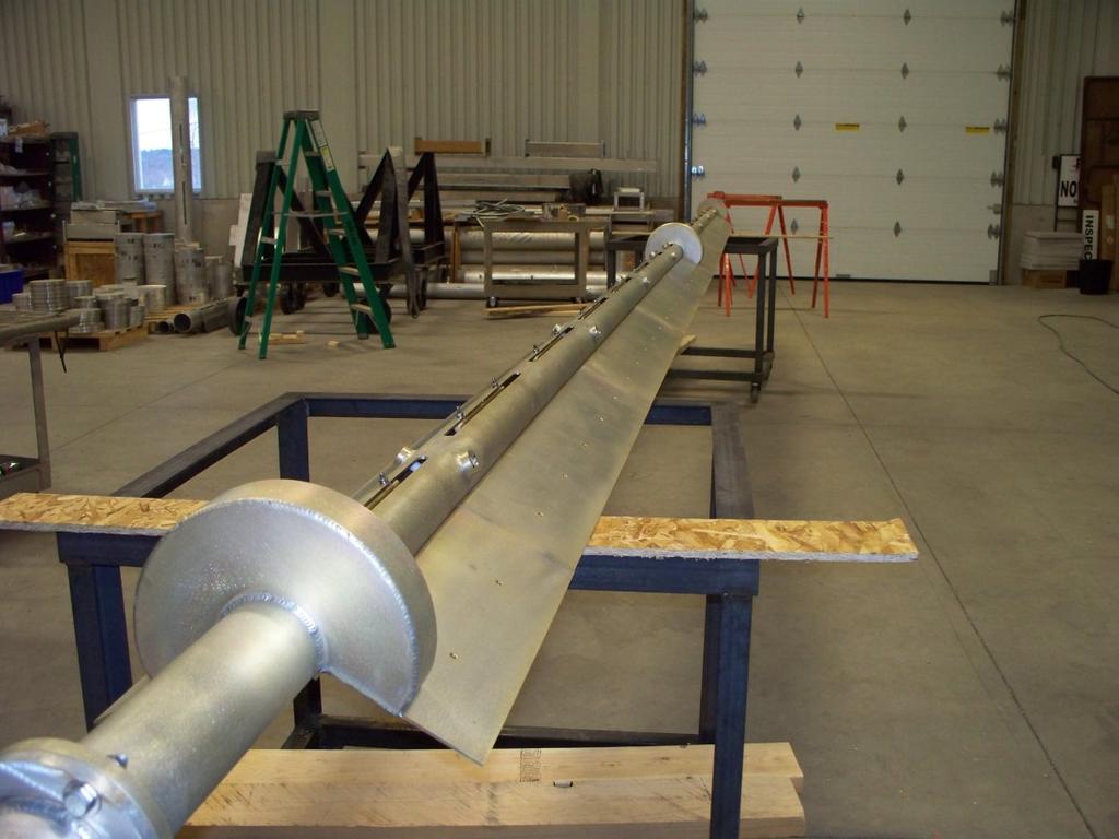
14 Review: How a slot antenna works The slot antenna is a TEM-Mode coaxial structure. Coupling structures inside the pylon will distort and couple to the fields in this coaxial antenna, causing a voltage to be applied directly across each of the slots in the antenna. This voltage alternates from plus to minus and back again at the channel frequency of operation. The length of the slots are adjusted so that the oscillating electric fields that develop across the gap that the slot creates will launch a radiating system of fields, propagating away from the antenna. 1λ ~ 0.8 λ If the coaxial pylon antenna is oriented vertically, with the slots cut in the outer conductor oriented vertically as well, the electrical fields across these slots will be oriented horizontally.

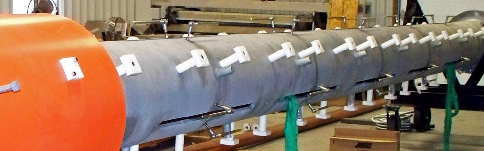
15 The E/P or C/P slot antenna Polarizer elements are mounted on either side of the slot. The polarizers are about 1/8 λ each and launch a vertically polarized electromagnetic field ¼ of a cycle or 90 degrees later than the horizontal field in quadrature. When axial the ratio between the two fields is equal we have Circular Polarization (C/P). When the horizontal field is stronger than the vertical we have elliptical polarization. For ATSC-M/H a 70/30 to 50/50 H to V ratio is ideal Channel 13 C/P Antenna

16 Did you know: Depending on the bay count and relative frequency versus element spacing, a Batwing style antenna can produce up to a 10% vertical component. Pictured here is a scaled to frequency channel 11 VHF batwing antenna.
17 How much vertical gain should we use and where do we aim the antenna at? First we need to answer some questions to help define the antenna parameters: 1. What ERP is needed, preferred transmitter size, and transmission line loss? 2. Who and where are we trying to cover with both OTA and ATSC-M/H? May not be the same goal! 3. Where is the transmitter (or multiple transmitter sites) in relation to the viewers? 4. Urban or rural area?
18 Let s Look At Four Sample Projects Project 1 A 48 kw DTV station in a city of 350,000 transmitting from an office building in the center of the city. 95% of the population is within 10 miles of the transmitter and the topography is flat. Antenna is 400 AGL. Most ATSC-M/H users would be within 3 miles of the transmitter. Project 2 A 15 kw LD station in a city of 2,000,000 transmitting from a mountain ridge that s 1800 feet higher than the valley. The core population runs from the edge of the mountain to about 6 miles from the transmitter. Project 3 a 400 kw DTV that is transmitting from a mountain at 7,700 feet AMSL. The core of the city 7.3 miles away is a big tourist draw and would make up the bulk of ATSC-M/H users. Project 4 Super-Duper World in Orlando wants to run ATSC-M/H up I-75 to the Georgia line in an distributed network. A number of 250 to 350 foot cell towers are available. Each station would be a 15 kw LD facility. Fairly flat land along the highway.
19 Project 1 a 48 kw DTV station at 400 AGL! There are two large universities within 3 miles prime mobile TV viewers You have a 5 kw transmitter and a tower on top a building in downtown. 95% of your viewers are within 10 miles the other 5% are outside that area. Antenna Pattern? Omnioid or Omni?! Remember the different patterns of an Omnioid versus Omni-directional? Omni please! Vertical Component? a 70/30 power split would provide an excellent vertical component. So your vertical ERP would be 3/7 * 48 kw or kw. Your total ERP in both planes would be kw. You have a 5 kw transmitter feeding a very short run of line kw/5 kw comes up to a minimum antenna vertical gain of A minimum of a 14 bay antenna would be needed!
20 Here is the 14 bay elevation pattern with 0.5 degrees of beam tilt we are going to use. We wanted fairly uniform field down to about -20 degrees to blanket the downtown area Main beam touchdown at 22 miles from tower This point is 2 miles from the tower This point is 1200 from the tower This point is 4000 from the tower Project 1
21 Project 1 Here is the same 14 bay antenna with the elevation plot shown in a Polar format, This is a low RFR specially spaced antenna.
22 Project 2 A 15 kw LD station on a ridge A 15 kw LD station is on a ridge 1800 feet from the valley floor. The close in population is 16 degrees below the horizon the distant population is up to 30 miles out at the horizon. Half of the population is within 10 miles. A broad cardioid pattern works well since the H and V Pol patterns are close. V Pol Azimuth H Pol Azimuth We have 2.5 kw TPO available so a fairly low gain antenna will work
23 Bay SFN 0.8 BT Bay SFN 1.0 BT 5.24 kw ERP ( db) kw ERP 759 Watts ERP ( db) Watts ERP Here are two elevation patterns to look at One is a 10 bay, the second is a 12 bay. The distant points in the valley where viewers are is between 0.0 and -0.7 degrees. The downtown core is at -4.0 degrees, the close in population starts at degrees
24 Project 3 A 400 kw DTV Station From a 7700 foot high mountain the station needs to cover the valley which has population starting at 4.8 miles from the transmitter site to 17.7 miles away at the end of the valley. The core of the city (7.3 miles away) is a large tourist draw, is about a mile in diameter and would be the largest concentration of ATSC-M/H users. The transmitter also feeds more than 20 translators and numerous CATV headends within 100 miles. Where are the viewers? Close in 4.8 miles away depression angle degrees Downtown Core 7.3 miles away depression angle degrees Far Valley 17.7 miles away depression angle degrees Out of city CATV s and Translators up to 100 miles away -0.5 to degrees Solve These Problems That The Station Has! A dual cabinet 40 kw transmitter that only likes being a 25 kw one! High Tower rental costs - $$ by the foot! Antenna on public land RFR needs to be contained
25 Project 3 Using an 18 bay low RFR antenna This point is miles from the transmitter This point is 7.3 miles From the transmitter This point is 4.8 miles from the transmitter
26 Project 4 Super Duper World SFN s Provide ATSC-M/H along I-75 to the thousands of cars that use the highway each day. Each site will be a 15 kw LD site with the antenna 250 to 300 feet AGL. A 1.5 kw transmitter is planned for each site. A wide peanut pattern with a horizontal azimuth gain of 2.20 has been filed on for each site. Peanut Pattern Rotated 130 Degrees --- H Pol --- V Pol Because of the way the parastitics are placed, the horizontal and vertical azimuth patterns are close. This is perfect for maximizing the signal along the highway
27 Project 4 The elevation pattern The 10 bay pattern we created earlier is perfect for the job. The field does not go to zero until it hits -40 degrees This point is 2450 from tower This point is 290 from the tower With 0.7 degrees of beam tilt the main beam hits the ground 4 miles from the tower the field value at the radio horizon is still 98.2%

28 Summary Plan your directional pattern carefully to ensure the vertical coverage is where it needs to be. The cost/benefit ratio maxes out with a 70/30 H/V split. Urban areas are a better case for C/P. The E/P or C/P antenna may increase the tower loading over a H Pol only model due to radome size. Lower gain antennas provide wider main beams and allow fuller control null fill.


29 Thank You! Questions? Lewiston Maine our hometown Bill Ammons
30 What our DTV neighbors in Canada are doing As of August 2011 most major markets have built out CBC has shut off 100 s of rebroadcasters Smaller market private broadcasters continue towards Digital A few high-band VHF stations are looking to UHF A few stations are looking at Mobile Handheld
31 Buildouts at reduced power A number of stations are being built out at a lower power or a lower tower height than planned. A large number of allocations were made on maximizing coverage area, not economic reality. Some of the factors are the extra costs to reach that last two or three miles, limitations on available tower space and long term hydro costs. If the outlying cable systems can get the signal it s good enough. People in outlying areas either use satellite or an outdoor antenna.
32 -- Azimuth Pattern B Rotated 0 Degrees --- Radio Nord Rouyn - Noranda UHF Theoretical Patttern Rather a strange azimuth pattern considering the nearest stations are almost 200 miles away.
33 Major Reception Issues The biggest problems have been with High-band VHF due to the very low PT ERP assignments. Here are a few: CHAN PT kw analog 0.65 kw digital CKVU PT kw analog 1.1 kw digital CHCH PT kw analog 6.1 kw digital* CHLT PT kw analog 4.0 kw digital CBRT PT kw analog 7.0 kw digital CFTM PT kw analog 11.0 kw digital *CHCH PT was an interesting example. With a 12 bay antenna, the field value over the city core was between 0.05 and ERP was only between 15 Watts and 137 Watts in the core 4 miles away.

34 The channel 5 slot antenna was stripped out and now is used to support the new channel 38/39 PT antenna. A channel 13 pylon is above this antenna. Halifax Nova Scotia


35 Rimouski, Quebec Channel 45 PT antenna Where is the falling ice coming from?

36 Chicotumini, Quebec city center site 16 Bay channel 6 antenna for analog Converted to channel 46 PT Microwave dish feeds secondary channel 10 rebroadcaster in Roberval, Quebec

37 A view of the new channel 46 digital antenna on the right side of the tower top New antenna is a dual fed 32 bay slot antenna.

38 Quebec City, Quebec New PT 17 antenna. Low band top mount antenna elements are being removed. This site is in city center. New vertical real estate for a future UHF side mount antenna

39 Mont Orford Sherbrooke-Magog, Quebec Original design for one TV and one FM on center monopole Now home to channel 7,9,24,27 and 30, plus one FM Site is at the top of a ski run so RFR is an important issue Candelabra is 75 feet above the ground High gust factor site and icing of 2 is not uncommon at 2790 feet above sea level

40 Mont Royal Montreal, Quebec 100 meters high Majority of TV and FM s in the market are here In a city park very strict RFR rules

41 Mont Royal close up of new channel 15,19,20 and 21 antennas
42 Warning!! The next slide is Graphic Do not attempt to do this at home or at work!

43 How NOT to install Air Flex transmission line. It looks like they ran out of threaded rod so the top support is two turnbuckles in series. Below the hoisting grip the line is not supported for 15 feet. A chain supporting the grip is routed over a pair of climbing pegs. The monopole is painted and the grounding kit lead wire is not bonded to ground.
44 Thank You!!
The Spectrum Repack: Is there a move to VHF in your future? Bill Ammons Broadcasters Clinic 2016
 The Spectrum Repack: Is there a move to VHF in your future? Bill Ammons Broadcasters Clinic 2016 Maybe a move to VHF in your future? A quick look back at the analog era model, what worked, what did not
Antenna Technology Bootcamp. NTA Show 2017 Denver, CO
 Antenna Technology Bootcamp NTA Show 2017 Denver, CO Review: How a slot antenna works The slot antenna is a TEM-Mode coaxial structure. Coupling structures inside the pylon will distort and couple to the
TPV-SFN Series Low RFR VHF Slot Pylon Antennas
 Channel 7-13 (Band III) Low RFR VHF Slot Antenna Omni-directional and Directional Patterns Available Top or Side Mount Models Horizontal, Elliptical, or Circular Polarization Available TPV-SFN Series Low
Antenna Design Seminar
 Antenna Design Seminar What we are going to cover This seminar will cover the design concepts of a variety of broadcast antennas that relates to the design of TV and FM antennas. We will first look at
700 and 800 MHz Band Slot Antennas
 Low Group Delay, Wide Bandwidth UHF Slot Antennas Omni-directional and Directional Patterns Available Low RFR Models Available Top or Side Mount Models Horizontal, Elliptical, or Circular Polarization
The TV Spectrum Re-Packing Antenna Engineering Guide V2.0
 The TV Spectrum Re-Packing Antenna Engineering Guide V2.0 Micronetixx is pleased to present this updated engineering guide to the TV Broadcast Industry. Many veterans of the Industry that work in the RF
Welcome to AntennaSelect Volume 4 November Where is the RFR at my site?
 Welcome to AntennaSelect Volume 4 November 2013 Welcome to Volume 4 of our newsletter AntennaSelect. Each month we will be giving you an under the radome look at antenna and RF technology. If there are
Welcome to AntennaSelect Volume 35 December 2017
 Welcome to AntennaSelect Volume 35 December 2017 Welcome to Volume 35 of our newsletter, AntennaSelect TM. Every two months we will be giving you an under the radome look at antenna and RF technology.
DL Series UHF Top Mount Slot Antennas
 Low Group Delay True Center Fed Design Wide Range of Standard And Custom Azimuth Patterns Available In 8 To 32 Bay Models, In 2 Bay Increments to 65 kw Input Power Ratings Horizontal, Elliptical and Circular
Repack Space Squeeze How Long is That FM Antenna? Multi-Bay Antennas and AM Translators
 Welcome to AntennaSelect Volume 27 August 2016 Welcome to Volume 27 of our newsletter, AntennaSelect TM. Every two months we will be giving you an under the radome look at antenna and RF Technology. If
Welcome to AntennaSelect Volume 1 August 2013
 Welcome to AntennaSelect Volume 1 August 2013 This is the first issue of our new periodic newsletter, AntennaSelect. AntennaSelect will feature informative articles about antennas and antenna technology,
Welcome to AntennaSelect Volume 33 August Micronetixx has moved into a larger facility
 Welcome to AntennaSelect Volume 33 August 2017 Welcome to Volume 33 of our newsletter, AntennaSelect TM. Every two months we will be giving you an under the radome look at antenna and RF technology. If
Welcome to AntennaSelect Volume 28 October 2016
 Welcome to AntennaSelect Volume 28 October 216 Welcome to Volume 28 of our newsletter, AntennaSelect TM. Every two months we will be giving you an under the radome look at antenna and RF Technology. If
Welcome to AntennaSelect Volume 20 June New FMM - mid power FM antennas
 Welcome to AntennaSelect Volume 20 June 2015 Welcome to Volume 20 of our newsletter, AntennaSelect TM. Each month we will be giving you an under the radome look at antenna and RF technology. If there are
360 inches (915 cm) 240 inches (610 cm) 120 inches (305 cm) 240 inches is the recommended pole length, 360 inches is the recommended free space area
 240 inches (610 cm) 120 inches (305 cm) 240 inches is the recommended pole length, 360 inches is the recommended free space area") FML C/P FM Antenna Right hand C/P Polarization Low wind load area Up to 1 kw Rating per bay Omni-directional Up to 8 kw input per array with power divider options The FML series of antennas are narrow
FML C/P FM Antenna Right hand C/P Polarization Low wind load area Up to 1 kw Rating per bay Omni-directional Up to 8 kw input per array with power divider options The FML series of antennas are narrow
Welcome to AntennaSelect Volume 10 May Optimizing VHF (Band III) Batwing antennas - Part 2
 Batwing antennas - Part 2") Welcome to AntennaSelect Volume 10 May 2014 Welcome to Volume 10 of our newsletter, AntennaSelect TM. Each month we will be giving you an under the radome look at antenna and RF technology. If there are
Welcome to AntennaSelect Volume 10 May 2014 Welcome to Volume 10 of our newsletter, AntennaSelect TM. Each month we will be giving you an under the radome look at antenna and RF technology. If there are
LPFM Antenna Applications and Engineering Guide
 LPFM Antenna Applications and Engineering Guide We have received a lot of questions from new LPFM station operators about how to get the best coverage for their station. We have answered some of these
FM Transmission Systems Course
 FM Transmission Systems Course Course Description An FM transmission system, at its most basic level, consists of the transmitter, the transmission line and antenna. There are many variables within these
Welcome to AntennaSelect Volume 34 October UHF and VHF Stacked Antenna Pylons
 Welcome to AntennaSelect Volume 34 October 2017 Welcome to Volume 34 of our newsletter, AntennaSelect TM. Every two months we will be giving you an under the radome look at antenna and RF Technology. If
Welcome to AntennaSelect Volume 40 October Update on Antenna Delivery Times:
 Welcome to AntennaSelect Volume 40 October 2018 Welcome to Volume 40 of our newsletter, AntennaSelect TM. Every two months we will be giving you an under the radome look at antenna and RF Technology. If
AL PLUS Series. Low and Medium Power UHF Television Antenna. Low and Medium Power UHF Antenna Systems. Features. Characteristics
 AL PLUS Series Features Fast delivery Light weight, low windload Quick, low-cost installation Four azimuth patterns available Up to 10 kw DTV (23 kw analog) input power rating 8- and 12-bay models Multichannel
Broadcast Antenna & Service Guide
 Telecommunications Broadcast Antenna & Service Guide Multiple Solutions Various Patterns and Gain Coaxial, Dipole and Patch Designs www.alivetele.com 2 Alive Telecom - Variety of Antenna System Solutions
First DTV Antenna on the Hancock Building Chicago, USA
 FRONT COVER (Front Cover Photo) UHF Top-mount Combined Antenna System Highest Power Antenna in Asia (Jakarta, Indonesia) First DTV Antenna on the Hancock Building Chicago, USA JAMPRO ANTENNAS, INC. Your
End Fed vs. Center Fed Slotted Coaxial Broadcast Antenna. Not a Choice of Preference
 End Fed vs. Center Fed Slotted Coaxial Broadcast Antenna Not a Choice of Preference John L. Schadler VP Engineering Dielectric Raymond, ME. Abstract The advantages of center feeding a slotted coaxial,
Polarization. Contents. Polarization. Types of Polarization
 Contents By Kamran Ahmed Lecture # 7 Antenna polarization of satellite signals Cross polarization discrimination Ionospheric depolarization, rain & ice depolarization The polarization of an electromagnetic
Half-Wave Dipole. Radiation Resistance. Antenna Efficiency
 Antennas Simple Antennas Isotropic radiator is the simplest antenna mathematically Radiates all the power supplied to it, equally in all directions Theoretical only, can t be built Useful as a reference:
P300/P350 Series. Vertically Polarized FM Antenna. Features. Characteristics
 Vertically Polarized FM Features Low VSWR, superior VSWR band width, minimal weather related VSWR problems Fully pressurized, internal feed, welded feed connections, series fed radiating elements High
ROTOTILLER. Circularly Polarized FM Antenna. Benefits. Characteristics
 Benefits Low VSWR, superior VSWR band width, and minimal weather related VSWR problems Fully pressurized, internal feed and welded feed connections High input power capacity Modular construction facilitates
Optimum elevation gain and zero radiation at 90 degrees can be achieved with
 Question John FM Antennas: One way to reduce downward RF signal near the tower is to use short -spaced element antennas. Is there another way it can be accomplished? 2 Optimum elevation gain and zero radiation
6 Radio and RF. 6.1 Introduction. Wavelength (m) Frequency (Hz) Unit 6: RF and Antennas 1. Radio waves. X-rays. Microwaves. Light
 Frequency (Hz) Unit 6: RF and Antennas 1. Radio waves. X-rays. Microwaves. Light") 6 Radio and RF Ref: http://www.asecuritysite.com/wireless/wireless06 6.1 Introduction The electromagnetic (EM) spectrum contains a wide range of electromagnetic waves, from radio waves up to X-rays (as
6 Radio and RF Ref: http://www.asecuritysite.com/wireless/wireless06 6.1 Introduction The electromagnetic (EM) spectrum contains a wide range of electromagnetic waves, from radio waves up to X-rays (as
Technician License. Course
 Technician License Course Technician License Course Chapter 4 Lesson Plan Module - 10 Practical Antennas The Dipole Most basic antenna The Dipole Most basic antenna The Dipole Total length is ½ wavelength
Chapter 15: Radio-Wave Propagation
 Chapter 15: Radio-Wave Propagation MULTIPLE CHOICE 1. Radio waves were first predicted mathematically by: a. Armstrong c. Maxwell b. Hertz d. Marconi 2. Radio waves were first demonstrated experimentally
FUTURE ANTENNA TECHNOLOGY FOR ATSC 3.0 J o h n L. S c h a d l e r
 FUTURE ANTENNA TECHNOLOGY FOR ATSC 3.0 J o h n L. S c h a d l e r M o r e, M o r e, M o r e More flexibility More services More robust delivery More platforms 4K UHDTV More signal strength How much signal
Welcome to AntennaSelect Volume 38 June Standing-Wave vs. Traveling-Wave
 Welcome to AntennaSelect Volume 38 June 2018 Welcome to Volume 38 of our newsletter, AntennaSelect TM. Every two months we will be giving you an under the radome look at antenna and RF Technology. If there
BENEFITS FOR DEPLOYABLE QUADRIFILAR HELICAL ANTENNA MODULES FOR SMALL SATELLITES
 BENEFITS FOR DEPLOYABLE ANTENNA MODULES FOR SMALL SATELLITES 436.5 and 2400 MHz QHA s compared with Monopole Antennas on Small Satellites 1 2400 MHZ ISO-FLUX ANTENNA MOUNTED ON A 2U SMALL SATELLITE Axial
New Concepts of Transmitting Antennas for DMB and DVB-H
 New Concepts of Transmitting Antennas for DMB and DVB-H Hermann Zehetner Head of Broadcast Antenna Development hermann.zehetner@kathrein.de with the support of: Dr. Norbert Ephan Senior Manager New Technology
BROADBAND AND HIGH GAIN OMNIS
 C WDA series antennas are optimized for both broadband and high gain performance. These antennas are ideally suited for use with frequency hopping radios and wideband jammers where tuning or band switching
Technician License. Course
 Technician License Course Technician License Course Chapter 4 Lesson Plan Module - 9 Antenna Fundamentals Feed Lines & SWR The Antenna System The Antenna System Antenna: Transforms current into radio waves
CHAPTER 8 ANTENNAS 1
 CHAPTER 8 ANTENNAS 1 2 Antennas A good antenna works A bad antenna is a waste of time & money Antenna systems can be very inexpensive and simple They can also be very expensive 3 Antenna Considerations
Satellite Sub-systems
 Satellite Sub-systems Although the main purpose of communication satellites is to provide communication services, meaning that the communication sub-system is the most important sub-system of a communication
Antennas Prof. Girish Kumar Department of Electrical Engineering India Institute of Technology, Bombay. Module - 1 Lecture - 1 Antennas Introduction-I
 Antennas Prof. Girish Kumar Department of Electrical Engineering India Institute of Technology, Bombay Module - 1 Lecture - 1 Antennas Introduction-I Hello everyone. Welcome to the exciting world of antennas.
Practical Antennas and. Tuesday, March 4, 14
 Practical Antennas and Transmission Lines Goals Antennas are the interface between guided waves (from a cable) and unguided waves (in space). To understand the various properties of antennas, so as to
ABOUT JAMPRO CONTINUING THE TRADITION
 JAMPRO ANTENNAS, INC. Your Partner for DTV-DVB-T & HD Radio Solutions- the oldest, most experienced broadcast antenna company in North America with over 50 years of experience providing Complete Turnkey
Antennas and Propagation Chapters T4, G7, G8 Antenna Fundamentals, More Antenna Types, Feed lines and Measurements, Propagation
 Antennas and Propagation Chapters T4, G7, G8 Antenna Fundamentals, More Antenna Types, Feed lines and Measurements, Propagation =============================================================== Antenna Fundamentals
FCC Technician License Course
 FCC Technician License Course 2014-2018 FCC Element 2 Technician Class Question Pool Presented by: Tamiami Amateur Radio Club (TARC) WELCOME To the third of 4, 3-hour classes presented by TARC to prepare
4 Antennas as an essential part of any radio station
 4 Antennas as an essential part of any radio station 4.1 Choosing an antenna Communicators quickly learn two antenna truths: Any antenna is better than no antenna. Time, effort and money invested in the
ANTENNAS FEED POINTS. An antenna is a mechanical structure by which electromagnetic waves are sent out or received.
 ANTENNAS An antenna is a mechanical structure by which electromagnetic waves are sent out or received. An antenna accomplishes this by being made so that its structure will be resonant at the frequency
EMG4066:Antennas and Propagation Exp 1:ANTENNAS MMU:FOE. To study the radiation pattern characteristics of various types of antennas.
 OBJECTIVES To study the radiation pattern characteristics of various types of antennas. APPARATUS Microwave Source Rotating Antenna Platform Measurement Interface Transmitting Horn Antenna Dipole and Yagi
CHAPTER 5 THEORY AND TYPES OF ANTENNAS. 5.1 Introduction
 CHAPTER 5 THEORY AND TYPES OF ANTENNAS 5.1 Introduction Antenna is an integral part of wireless communication systems, considered as an interface between transmission line and free space [16]. Antenna
Technician License Course Chapter 4. Lesson Plan Module 9 Antenna Fundamentals, Feed Lines & SWR
 Technician License Course Chapter 4 Lesson Plan Module 9 Antenna Fundamentals, Feed Lines & SWR The Antenna System Antenna: Transforms current into radio waves (transmit) and vice versa (receive). Feed
UHF Band IV-V TV Antennas I230E Series -4 dipoles Panels-
 Broadcast Antennas TV UHF UHF Band IV-V TV Antennas I230E Series -4 dipoles Panels- Electrical characteristics I230 EH I230 EV I230 EC Frequency range (MHz) 470-860 Input impedance (ohm) 50 Horizontal
Technician License Course Chapter 4
 Technician License Course Chapter 4 Propagation, Basic Antennas, Feed lines & SWR K0NK 26 Jan 18 The Antenna System Antenna: Facilitates the sending of your signal to some distant station. Feed line: Connects
TV Propagation & Multi-Path Effects Jim Andrews, KH6HTV
 AppNote7b-TVprop.doc (kh6htv, 10/30/2014) p. 1 of 7 Application Note AN-7b copyright - Oct. 2011 rev. - Oct. 2014 TV Propagation & Multi-Path Effects Jim Andrews, KH6HTV www.kh6htv.com Note: The original
Colubris Networks. Antenna Guide
 Colubris Networks Antenna Guide Creation Date: February 10, 2006 Revision: 1.0 Table of Contents 1. INTRODUCTION... 3 2. ANTENNA TYPES... 3 2.1. OMNI-DIRECTIONAL ANTENNA... 3 2.2. DIRECTIONAL ANTENNA...
UNIT Derive the fundamental equation for free space propagation?
 UNIT 8 1. Derive the fundamental equation for free space propagation? Fundamental Equation for Free Space Propagation Consider the transmitter power (P t ) radiated uniformly in all the directions (isotropic),
Newsletter 4.4. Antenna Magus version 4.4 released! Array synthesis reflective ground plane addition. July 2013
 Newsletter 4.4 July 2013 Antenna Magus version 4.4 released! We are pleased to announce the new release of Antenna Magus Version 4.4. This release sees the addition of 5 new antennas: Horn-fed truncated
Micronetixx Technologies, LLC ~ Photo Gallery
 Micronetixx Technologies, LLC ~ Photo Gallery Airborne Military Aircraft-Nose Horn Antenna Array Ultra-High Power, (500 Megawatt), Vacuum Waveguide Orthogonal Mode Transducer for the Military High-Power
Data and Computer Communications. Tenth Edition by William Stallings
 Data and Computer Communications Tenth Edition by William Stallings Data and Computer Communications, Tenth Edition by William Stallings, (c) Pearson Education - Prentice Hall, 2013 Wireless Transmission
Chapter 6 Antenna Basics. Dipoles, Ground-planes, and Wires Directional Antennas Feed Lines
 Chapter 6 Antenna Basics Dipoles, Ground-planes, and Wires Directional Antennas Feed Lines Some General Rules Bigger is better. (Most of the time) Higher is better. (Most of the time) Lower SWR is better.
Fundamentals of Antennas. Prof. Ely Levine
 Fundamentals of Antennas Prof. Ely Levine levineel@zahav.net.il 1 Chapter 3 Wire Antennas 2 Types of Antennas 3 Isotropic Antenna Isotropic radiator is the simplest antenna mathematically Radiates all
Amateur Radio License. Propagation and Antennas
 Amateur Radio License Propagation and Antennas Todays Topics Propagation Antennas Propagation Modes Ground wave Low HF and below, ground acts as waveguide Line-of-Sight (LOS) VHF and above, radio waves
Unguided Media and Matched Filter After this lecture, you will be able to Example?
 Unguided Media and Matched Filter After this lecture, you will be able to describe the physical and transmission characteristics of various unguided media Example? B.1 Unguided media Guided to unguided
UNIT Write short notes on travelling wave antenna? Ans: Travelling Wave Antenna
 UNIT 4 1. Write short notes on travelling wave antenna? Travelling Wave Antenna Travelling wave or non-resonant or aperiodic antennas are those antennas in which there is no reflected wave i.e., standing
Lecture 2: The Concept of Cellular Systems
 Radiation Patterns of Simple Antennas Isotropic Antenna: the isotropic antenna is the simplest antenna possible. It is only a theoretical antenna and cannot be realized in reality because it is a sphere
Antennas Prof. Girish Kumar Department of Electrical Engineering Indian Institute of Technology, Bombay. Module 2 Lecture - 10 Dipole Antennas-III
 Antennas Prof. Girish Kumar Department of Electrical Engineering Indian Institute of Technology, Bombay Module 2 Lecture - 10 Dipole Antennas-III Hello, and welcome to todays lecture on Dipole Antenna.
The Basics of Patch Antennas, Updated
 The Basics of Patch Antennas, Updated By D. Orban and G.J.K. Moernaut, Orban Microwave Products www.orbanmicrowave.com Introduction This article introduces the basic concepts of patch antennas. We use
Lesson 11: Antennas. Copyright Winters Version 1.0. Preparation for Amateur Radio Technician Class Exam
 Lesson 11: Antennas Preparation for Amateur Radio Technician Class Exam Topics Antenna ½ wave Dipole antenna ¼ wave Vertical antenna Antenna polarization Antenna location Beam antennas Test Equipment Exam
Part 10: Application Procedures and Rules for Digital Television (DTV) Undertakings
 Undertakings") Issue 2 February 2016 Spectrum Management and Telecommunications Broadcasting Procedures and Rules Part 10: Application Procedures and Rules for Digital Television (DTV) Undertakings Aussi disponible en
Issue 2 February 2016 Spectrum Management and Telecommunications Broadcasting Procedures and Rules Part 10: Application Procedures and Rules for Digital Television (DTV) Undertakings Aussi disponible en
4/29/2012. General Class Element 3 Course Presentation. Ant Antennas as. Subelement G9. 4 Exam Questions, 4 Groups
 General Class Element 3 Course Presentation ti ELEMENT 3 SUB ELEMENTS General Licensing Class Subelement G9 Antennas and Feedlines 4 Exam Questions, 4 Groups G1 Commission s Rules G2 Operating Procedures
The A-B-C's of Radio Waves and Antennas
 The A-B-C's of Radio Waves and Antennas By Greg S. Carpenter GregsBasicElectronics.com What is the most important thing in common with both the transmitter and receiver? It's the antenna and without a
Sw earth Dw Direct wave GRw Ground reflected wave Sw Surface wave
 WAVE PROPAGATION By Marcel H. De Canck, ON5AU Electromagnetic radio waves can propagate in three different ways between the transmitter and the receiver. 1- Ground waves 2- Troposphere waves 3- Sky waves
P. 1 of 18 REPORT 1.1. TV ANTENNA RECONSTITUTION P. 1 of 18. Commercial in Confidence SAMPLE SITE (TV). 3 MARCH 2017.
. 3 MARCH 2017.") P. 1 of 18 Commercial in Confidence REPORT 1.1 TV ANTENNA RECONSTITUTION P. 1 of 18 SAMPLE SITE (TV). 3 MARCH 2017. 1/ EXECUTIVE SUMMARY Sixarms has been commissioned by the Client to verify the performance
P. 1 of 18 Commercial in Confidence REPORT 1.1 TV ANTENNA RECONSTITUTION P. 1 of 18 SAMPLE SITE (TV). 3 MARCH 2017. 1/ EXECUTIVE SUMMARY Sixarms has been commissioned by the Client to verify the performance
Essentia Electromagnetic Monitor Model: EM2
 Essentia Electromagnetic Monitor Model: EM2 The Essentia EM2 was designed to bridge the gap between inexpensive monitors with limited response and expensive full spectrum units. It has a small, sensitive
Introduction. TV Coverage and Interference, February 06, 2004.
 A New Prediction Model for M/H Mobile DTV Service Prepared for OMVC June 28, 2011 Charles Cooper, du Treil, Lundin & Rackley, Inc. Victor Tawil, National Association of Broadcasters Introduction The Open
I J E E Volume 5 Number 1 January-June 2013 pp
 I J E E Volume 5 Number 1 January-June 2013 pp. 21-25 Serials Publications, ISSN : 0973-7383 Various Antennas and Its Applications in Wireless Domain: A Review Paper P.A. Ambresh 1, P.M. Hadalgi 2 and
4/25/2012. Supplement T9. 2 Exam Questions, 2 Groups. Amateur Radio Technician Class T9A: T9A: T9A: T9A:
 Amateur Radio Technician Class Element 2 Course Presentation ti ELEMENT 2 SUB-ELEMENTS Technician Licensing Class Supplement T9 Antennas, Feedlines 2 Exam Questions, 2 Groups T1 - FCC Rules, descriptions
KULLIYYAH OF ENGINEERING
 KULLIYYAH OF ENGINEERING DEPARTMENT OF ELECTRICAL & COMPUTER ENGINEERING ANTENNA AND WAVE PROPAGATION LABORATORY (ECE 4103) EXPERIMENT NO 3 RADIATION PATTERN AND GAIN CHARACTERISTICS OF THE DISH (PARABOLIC)
Class Overview. Antenna Fundamentals Repeaters Duplex and Simplex Nets and Frequencies Cool Radio Functions Review
 Class Overview Antenna Fundamentals Repeaters Duplex and Simplex Nets and Frequencies Cool Radio Functions Review Antennas Antennas An antenna is a device used for converting electrical currents into electromagnetic
Antenna Fundamentals Basics antenna theory and concepts
 Antenna Fundamentals Basics antenna theory and concepts M. Haridim Brno University of Technology, Brno February 2017 1 Topics What is antenna Antenna types Antenna parameters: radiation pattern, directivity,
Technician Licensing Class T9
 Technician Licensing Class T9 Amateur Radio Course Monroe EMS Building Monroe, Utah January 11/18, 2014 January 22, 2014 Testing Session Valid dates: July 1, 2010 June 30, 2014 Amateur Radio Technician
DAB field trials in Finland
 DAB field trials in Finland V. Erkkilä M. Jokisalo (Yleisradio Oy) Original language: English Manuscript received 27/10/1994 The DAB logo has been registered by a member of the Eureka 147 DAB consortium.
FM Wide Band Panel Dipole Antenna
 IEEE TRANSACTIONS ON BROADCASTING, VOL. 48, NO. 4, DECEMBER 2002 317 FM Wide Band Panel Dipole Antenna Valentín Trainotti, Senior Member, IEEE and Norberto Dalmas Di Giovanni, Member, IEEE Abstract It
Part 10: Application Procedures and Rules for Digital Television (DTV) Undertakings
 Undertakings") Issue 1 August 2010 Spectrum Management and Telecommunications Broadcasting Procedures and Rules Part 10: Application Procedures and Rules for Digital Television (DTV) Undertakings Aussi disponible en
Issue 1 August 2010 Spectrum Management and Telecommunications Broadcasting Procedures and Rules Part 10: Application Procedures and Rules for Digital Television (DTV) Undertakings Aussi disponible en
New Antenna Designs for DTV Implementation
 New Antenna Designs for DTV Implementation JOHN L. SCHADLER and KERRY COZAD Dielectric Communications Raymond, Maine ABSTRACT WIDE BAND CAVITY ANTENNA (TFU-WB) Over the past few years the implementation
Presentation Title Subhead Date
 Getting The Most Out Of Your Wireless Mics Presentation Title Subhead Date Best Practices: Antennas, RF Coordination & Hardware Dave Mendez Senior Market Development Specialist The Wisdom of Dilbert Antennas:
3000 Series Granger Broadband HF Multi-Mode SPIRA-CONE Antennas
 3000 Series Granger Broadband HF Multi-Mode SPIRA-CONE Antennas 2 to 30 MHz Frequency Range, Dependent Upon Up to KW Average, 40 KW Peak Power Rating Horizontal-Elliptical to Reduce Fading Log-Periodic
Unguided Transmission Media
 CS311 Data Communication Unguided Transmission Media by Dr. Manas Khatua Assistant Professor Dept. of CSE IIT Jodhpur E-mail: manaskhatua@iitj.ac.in Web: http://home.iitj.ac.in/~manaskhatua http://manaskhatua.github.io/
Transmission Media. Transmission Media 12/14/2016
 Transmission Media in data communications DDE University of Kashmir By Suhail Qadir System Analyst suhailmir@uok.edu.in Transmission Media the transmission medium is the physical path between transmitter
M2 Antenna Systems, Inc. Model No: 2M HO LOOP
 M2 Antenna Systems, Inc. Model No: 2M HO LOOP SPECIFICATIONS: Model... 2M HO LOOP Frequency Range... 144 To 144.5 MHz Gain, Typical @ 10 ft.... 4 dbd @ 10 deg. Gain, 2 STK @ 82 & 132... 8 dbd @ 9 deg.
R&D White Paper WHP 058. Diversity reception of Digital Terrestrial Television (DVB-T) Research & Development BRITISH BROADCASTING CORPORATION
 Research & Development BRITISH BROADCASTING CORPORATION") R&D White Paper WHP 58 April 23 Diversity reception of Digital Terrestrial Television (DVB-T) J. Mitchell and J.A. Green Research & Development BRITISH BROADCASTING CORPORATION BBC Research & Development
R&D White Paper WHP 58 April 23 Diversity reception of Digital Terrestrial Television (DVB-T) J. Mitchell and J.A. Green Research & Development BRITISH BROADCASTING CORPORATION BBC Research & Development
TAP 6 Demo Quick Tour
 TAP 6 Demo Quick Tour Sales Contact: Curt Alway P.O. Box 7205 Charlottesville, VA 22906 Voice: 303-344-5486, Ext 1 Fax: 303-265-9399 Email: sales@softwright.com Technical Contact: Todd Summers, Ph.D. P.O.
Transforms and electrical signal into a propagating electromagnetic wave OR vise versa. - Transducer goes both ways. TX and RX antennas have
 Gary Rondeau AF7NX Transforms and electrical signal into a propagating electromagnetic wave OR vise versa. - Transducer goes both ways. TX and RX antennas have different jobs. For TX want to generate as
Notes 21 Introduction to Antennas
 ECE 3317 Applied Electromagnetic Waves Prof. David R. Jackson Fall 018 Notes 1 Introduction to Antennas 1 Introduction to Antennas Antennas An antenna is a device that is used to transmit and/or receive
DIY 137 MHz APT Weather satellite antenna Or, do we need a circular polarization?
 DIY 137 MHz APT Weather satellite antenna Or, do we need a circular polarization? What we are listening At the moment there are three NOAA satellites available transmitting the APT weather pictures in
Multimedia Training Kit
 Multimedia Training Kit Antennas and Cables Alberto Escudero Pascual, IT+46 Goals Focus on explaining the losses in the link budget equation Introduce a set of types of antennas and cables How to make
Yagi Antenna Tutorial. Copyright K7JLT 1
 Yagi Antenna Tutorial Copyright K7JLT Yagi: The Man & Developments In the 920 s two Japanese electrical engineers, Hidetsugu Yagi and Shintaro Uda at Tohoku University in Sendai Japan, investigated ways
Technician License Course Chapter 4. Lesson Plan Module 10 Practical Antennas
 Technician License Course Chapter 4 Lesson Plan Module 10 Practical Antennas The Dipole Most basic antenna Total length is ½ wavelength (½ λ) Usual construction: Two equal halves of wire, rod, or tubing
TACTICAL DIRECTORY ANTENNA DIAGRAM 3 INTRODUCTION LARGE OR SMALL INDOOR OR OUTDOOR EXTERNAL OR INTEGRATED US, EU, OR GLOBAL ENERGY FLOW
 TACTICAL DIRECTORY DIAGRAM 3 INTRODUCTION LARGE OR SMALL INDOOR OR OUTDOOR EXTERNAL OR INTEGRATED US, EU, OR GLOBAL ENERGY FLOW CIRCULAR OR LINEAR POLARIZATION DIAGRAM FAR FIELD OR NEAR FIELD FAR FIELD
stacking broadside collinear
 stacking broadside collinear There are three primary types of arrays, collinear, broadside, and endfire. Collinear is pronounced co-linear, and we may think it is spelled colinear, but the correct spelling
MITIGATING INTERFERENCE ON AN OUTDOOR RANGE
 MITIGATING INTERFERENCE ON AN OUTDOOR RANGE Roger Dygert MI Technologies Suwanee, GA 30024 rdygert@mi-technologies.com ABSTRACT Making measurements on an outdoor range can be challenging for many reasons,