Antenna Design Seminar
|
|
|
- Shona Newman
- 5 years ago
- Views:
Transcription


1 Antenna Design Seminar
2 What we are going to cover This seminar will cover the design concepts of a variety of broadcast antennas that relates to the design of TV and FM antennas. We will first look at antenna directivity and azimuth pattern performance. The second half of the seminar will look at the elevation patterns of antennas, and the effects of these patterns on RFR levels.
3 Azimuth Patterns The azimuth pattern is the horizontal directivity of the antenna. For broadcast applications we usually think of omnidirectional or directional patterns. Omnidirectional patterns can have as much as +/- 2 db directivity, while a directional azimuth pattern can have up to a 30 db ratio between the peak maxima and the smallest minima
 Pattern: Omnidirectional for 330 1.0 0.9 0.8 0.7 0 30 Series1 300 0.6 0.5 60 0.4 0.3 0.2 0.1 270 0.")
4 Typical Omni-directional Patterns Micronetixx Communicationsy Azimuth Gain 1.20 (0.79 db) Pattern: Omnidirectional for Series N-S W-E VHF Batwing Antenna

5 VHF Batwing Power Divider Feed point
6 Typical Omni-directional Patterns RF Technologies LLC - a Ferrite Company Azimuth Gain 1.3 (1.14 db) Pattern: 3 Panel Omnidirectional Series Panel VHF/FM Omni-directional Azimuth pattern with panels at 120 degrees and reflectors touching.
7 Typical Omni-directional Patterns RF Technologies LLC Azimuth Gain 1.11 (0.45 db) Pattern: 4 Slot Omnidirectional Series1 Slots 4 places Pylon diameter of 10 to 12 inches for UHF 18 to 22 inches for VHF Slot Omni-Directional VHF or UHF Slot Antenna
8 Typical Omni-directional Patterns RF Technologies - a Ferrite Company Azimuth Gain=1.13 (0.53 db) Azimuth Pattern= 3 slot omni O3 UHF Azimuth Pattern Slots per bay 120 degrees apart Slot Omni-directional VHF or UHF slot antenna. A 6 inch pylon is used for UHF, a 14 to 20 inch for VHF

9 A 3 slot around Omni-directional VHF Pylon antenna on channel 13
10 Typical Omni-directional Patterns RF Technologies - a Ferrite Company Azimuth Gain = 1.70 (2.30 db) Pattern: Omnioid Relative Field Value (%) 30 Relative Field Value (%) Slot This pattern is often used as an omni-directional pattern, It s the easiest to build antenna with one slot per bay and no parasitic elements. For UHF a 3 to 4 inch pylon is used, for VHF a 10 to 12 inch pylon is used.
11 Directional Azimuth Patterns Directional azimuth patterns are accomplished by adding parasitics to the antenna or by using uneven power division to the antenna elements or slots. For slot antennas parasitics are almost always used, except in multi slot per bay antenna designs. Panel and Batwing antenna use power division to build patterns.
12 Basic Directional Patterns RF Technologies - a Ferrite Company Azimuth Gain:1.90 (2.78 db) D Pattern: Cardioid -270 Degree Relative Field Value (%) Relative Field Value (%) Slot This is a broad cardioid pattern and is formed with a single slot and two angled wings. The length of the wings is frequency dependent.
13 Basic Directional Patterns RF Technologies - a Ferrite Company Azimuth Gain = 3.80 (5.80 db) RFT "F" Pattern - Skull Series Slot A narrower cardioid or skull pattern that is formed with a single slot and two wings at 180 degrees. The wings are frequency dependent. The next slide shows a channel 20 antenna with this pattern.

14 Here is an example of the skull pattern antenna from the previous slide. These are two 7 bay halves to form a 14 bay center fed antenna,
15 Basic Directional Patterns RF Technologies - a Ferrite Company Azimuth Gain = 3.60 (5.56 db) Pattern: G Skull-Reduced Rear Series1 Slot A reduced cardioid with a higher front to back ratio. The reduced rear pattern uses a second parasitic behind the pylon to reduce the radiation to the rear.
16 Basic Directional Patterns RF Technologies - a Ferrite Company Azimuth Gain: 2.1 (3.22 db) Pattern: 5771 Peanut Special Slot Series Slot This peanut pattern uses two slots per bay, 180 degrees from each other. Two small wings help form the two smaller maximas.
17 Basic Directional Patterns RF Technologies - a Ferrite Company Azimuth Gain = 2.2 (3.42 db) Pattern: Peanut-Standard Pattern Designator: H Relative Field Value (%) Slot Relative Field Value (%) Slot This peanut pattern uses two opposing slots per bay with two sets of wings to form the main beams. The wings are very frequency sensitive with this pattern.

18 The previous slide had a plot of a peanut pattern antenna. Here is the end of the antenna.
19 Special Directional Patterns Batwing Peanut pattern RF Technologies LLC -a Ferrite Company Special Peanut Pattern Batwing Azimuth Gain 2.25 (3.52 db) Batwing Peanut pattern N W E S Special Batwing peanut pattern. East - West elements are fed with only 25% power 180
20 Special Directional Patterns RF Technologies - a Ferrite Company Azimuth Gain = 1.52 (1.81 db) Pattern:Special Peanut 75 % power Series N W E S This antenna has a 75% power ratio to the East and West elements to make a fatter peanut pattern
21 Elevation Patterns The vertical pattern of an antenna and how well it s focused on your viewers determines how well your station fare in the marketplace. In 99% of cases your viewers are a few degrees below the horizon (except for a part of Anchorage, Alaska). Most of the distant viewers (2 to 60 miles away) are between -1 and -4 degrees below the horizon. In markets with high mountain transmitter sites and close in population (El Paso, Salt Lake City, Vancouver) viewers can easily be between -4 and -10 degrees below the horizon. A very broad low gain pattern can take up a lot of transmitter power to make the licensed ERP, while a high gain antenna can shoot it s main lobe over nearby potential viewers. Let s look at some basics of antenna elevation patterns.
22 Antenna Elevation Patterns ARRAY RADIATION PATTERN Let s take a look at arrays and array radiation patterns a little more closely. To do this, it s very helpful to consider a simple linear array of two elemental radiators, each transmitting their signals in all directions equally, as shown in Figure 1 below, (the two elemental radiators are not distinctly shown): These two theoretical point source radiators are commonly called isotropic elemental radiators. If these two elements are uniformly excited, (with the same magnitude and the same phase relative to one another), and are spaced at one full wavelength on center, the array pattern from these elemental radiators peaks to a maximum at zero degrees elevation angle, which is exactly broadside to the array. This is usually the desired result, since vertically placed television broadcast antennas literally fire their signals broadside toward their viewing audiences. However, another field maximum also occurs. This field maximum lies exactly along the axis if the array, above and below the antenna as shown. Figure 1
23 Antenna Elevation Patterns ARRAY RADIATION PATTERN With practical television broadcast antennas, the individual elemental radiators do not transmit their signals in an isotropic fashion, or in all directions equally. These practical elements radiate their signals broadside much more strongly as shown in Figure 2 below. (Figure 2 is a of a single practical dipole radiator. Please note there is no appreciable field along the array axis) Figure 2
24 Antenna Elevation Patterns Most antennas have vertical spacing of 1 wavelength (Lambda) between vertical elements. We will first look at the slot antenna, which is the most popular antenna type currently in North America. Another popular antenna is the VHF batwing antenna. The base design of the antenna is also 1 wavelength. A new version of the batwing antenna with wavelength was introduced a few years ago to reduce RFR at short tower sites. VHF panel and FM antennas are normally spaced at 1 wavelength, with many versions of antennas using 0.75, and 0.5 wavelength spacing,
25 Some Useful Terms Beam Tilt The amount of tilt in degrees that the main lobe is tilted downward by electrically short spacing the top elements of the array, or by mechanically tilting the antenna downward. Electrical and Mechanical beam tilt can be used at the same time to increase the over all depression of the main lobe Null Fill The amount of field that is added between the main lobe and the first and/or second secondary lobes. Null fill keeps the field values from going to zero close to the main beam. Values of 5 to 20% are common and are added by short spacing the top elements of the array. Beam Sway The difference in relative field over the bandwidth of the antenna. At a given depression angle of let s say -10 degrees, the field value of the low end the operating band is 0.16 of full field and at the top end of the band it s 0.19 of full field thus giving you a beam sway of 0.03 of peak field (or signal level) across the band.
26 SLOT ANTENNA BASICS DESIGN OF A STANDARD SLOT ANTENNA Arranged in an array, and placing the individual elements such that their unit radiated field maxima align with the broadside array field maxima when placed in a linear array such as is shown in Figure Five 3, a practical and useful linear array antenna results. ~1 λ ~0.8λ Figure 3
27 A Cartesian plot of a 4 bay and 8 bay one wavelength spaced antenna. These elevation patterns have no beam tilt or null fill.
28 Here are the same two elevation patterns, presented in polar form. The four bay pattern is on the left the eight bay pattern is on the right. The Cartesian plots are linear percentage of peak field the polar plots are in relative power. The scale of the polar graph is 40 db.
29 A Cartesian plot of a 12 and 16 bay one wavelength spaced antennas. Note the 16 bay pattern has a little null fill but no beam tilt.
30 Here are the two same elevation patterns presented in polar form. The 12 bay is on the left the 16 bay on the right.
31 Feed Systems for UHF Antennas There are several feed system designs for antennas. Panel and Batwing antennas are branch fed from a single or dual input. Larger UHF slot antennas can also be branch fed. Dipole and slot antennas can also be end fed from the end of the array. This design is best used on short bay count antennas. Longer slot antennas are usually center fed, or built up of multiple short bay sections.

32 Here is a center fed 8 bay UHF slot antenna. The input tee divides the power in two to fed the two 4 bay sections
, the antenna is built as two center fed 20 bay (four 10 bay sections) antennas, with a branch feed system.")
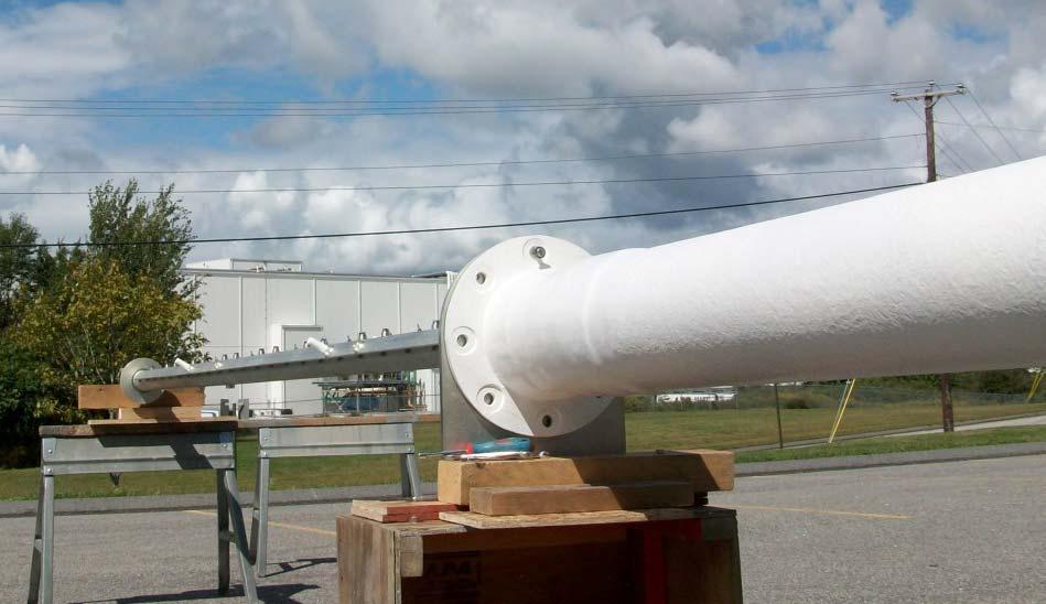
33 Here is a branch fed UHF slot antenna. This is a 40 bay antenna. To minimize beam sway (which we will discuss next), the antenna is built as two center fed 20 bay (four 10 bay sections) antennas, with a branch feed system. This antenna could also have been built as 4 10 bay sections, fed from a 4 way power divider. This antenna had a V.S.W.R. of less than 1:1.05 over the channel. This is a 3 slot around omnidirectional antenna, and is 76 feet long.
34 Beam Sway The next set of slides will compare beam sway of several antennas 8 Bay SFNstar End Fed Antenna 8 Bay SFNstar Center Fed Antenna 10 Bay SFNstar End Fed Antenna 10 Bay SFNstar Center Fed Antenna 12 Bay SFNstar Center Fed Antenna 16 Bay SFNstar Center Fed Antenna
35 8 Bay End Fed SFNstar antenna beam sway plot Low Mid High
36 8 Bay Center Fed SFNstar antenna beam sway plot Low Mid High
37 10 Bay End Fed SFNstar antenna beam sway plot Low Mid High
38 10 Bay Center Fed SFNstar antenna beam sway plot Low Mid High
39 12 Bay Center Fed SFNstar antenna beam sway plot Low Mid High
40 16 Bay Center Fed SFNstar antenna beam sway plot Low Mid High
41 16 Bay Center Fed SFNstar antenna beam sway plot Low Mid High A difference of 15% The 16 bay plot with an expanded scale note the field value difference at degrees
42 Designing Antennas to lower RFR For broadcasters the perfect antenna would concentrate all of the radiation from the horizon to about 10 degrees below the horizon. In reality most antennas place a good deal of radiation at higher depression angles, and above the horizon. On short tower or rooftop mounted sites, RFR can be a real problem. One problem with standard spaced (1 Wavelength) antennas is the residual grazing lobes at about +/- 80 degrees do not decrease with bigger bay count antennas. The last grazing lobe is usually the one to cause the worst RFR problem as you will see on the next slide.
43 A Cartesian plot of a 4 bay antenna (ORANGE), 8 bay antenna (GREEN), 12 bay antenna (BLUE), and 16 bay antenna (RED). (Note the same relative field value at ~ -80 to -90 degrees for all antennas.) This example is valid for all 1 wavelength spaced antennas.
44 Cartesian plot of four SFNstar Antennas the 4 bay is in BLUE, the 8 bay in RED, the 12 bay A in GREEN, the 16 bay is in ORANGE. Note the much smaller high axial angle grazing lobes on these antennas.
45 Polar plot of a 4-bay SFNstar antenna. The lowest grazing lobe is more than 24 db below the main lobe. Polar plot of an 8-bay SFNstar antenna. Here lowest grazing lobe is more than 33 db below the main lobe.
46 Here is a elevation plot of a 6 bay VHF antenna the red plot is a 360 degree spaced antenna the blue plot is a 315 degree spaced antenna
47 Where are the RFR hot spots? The next few slides will show you where the RFR hot spots are for a few sample antennas. We will look at both UHF and VHF applications.
48 2007 Ferrite/ RF Technologies A power density plot of a 10 bay channel 11 standard batwing antenna (RED), versus a 10 bay optimally spaced batwing antenna (BLUE). ERP is 90 kw height is 300 feet.
49 2007 Ferrite/ RF Technologies A power density plot of a 8 bay standard antenna, (RED), versus an 8 bay SFNstar antenna, (BLUE). (ERP: 30 kw; Height is 22 feet.)
50 2007 Ferrite/ RF Technologies A plot of just the 8-bay SFNstar antenna. (Again, ERP: 30 kw; height above the measuring plane is 22 feet.)
51 2007 Ferrite/ RF Technologies A power density plot of a 16-bay standard antenna (RED), versus a 16 bay SFNstar antenna, (BLUE). (ERP is 30 kw height is 22 feet.)
52 2007 Ferrite/ RF Technologies A Power Density Plot of the 16 bay SFNstar Antenna alone. (ERP is 30 kw height is 22 feet. Please notice the Units on the Power Density axis.)
53 Here is a RFR plot of 6 bay antennas 200 feet up with an ERP of 75 kw - the red plot is a standard spaced antenna the blue is a 315 degree spaced antenna
54 Here is a expanded view of the last slide with a 200 foot scale
55 Questions? Contact Information William Ammons Commercial Street, Lewiston, Maine U.S.A. +(207)
700 and 800 MHz Band Slot Antennas
 Low Group Delay, Wide Bandwidth UHF Slot Antennas Omni-directional and Directional Patterns Available Low RFR Models Available Top or Side Mount Models Horizontal, Elliptical, or Circular Polarization
The Spectrum Repack: Is there a move to VHF in your future? Bill Ammons Broadcasters Clinic 2016
 The Spectrum Repack: Is there a move to VHF in your future? Bill Ammons Broadcasters Clinic 2016 Maybe a move to VHF in your future? A quick look back at the analog era model, what worked, what did not
Antenna Technology Bootcamp. NTA Show 2017 Denver, CO
 Antenna Technology Bootcamp NTA Show 2017 Denver, CO Review: How a slot antenna works The slot antenna is a TEM-Mode coaxial structure. Coupling structures inside the pylon will distort and couple to the
TPV-SFN Series Low RFR VHF Slot Pylon Antennas
 Channel 7-13 (Band III) Low RFR VHF Slot Antenna Omni-directional and Directional Patterns Available Top or Side Mount Models Horizontal, Elliptical, or Circular Polarization Available TPV-SFN Series Low
Welcome to AntennaSelect Volume 10 May Optimizing VHF (Band III) Batwing antennas - Part 2
 Batwing antennas - Part 2") Welcome to AntennaSelect Volume 10 May 2014 Welcome to Volume 10 of our newsletter, AntennaSelect TM. Each month we will be giving you an under the radome look at antenna and RF technology. If there are
Welcome to AntennaSelect Volume 10 May 2014 Welcome to Volume 10 of our newsletter, AntennaSelect TM. Each month we will be giving you an under the radome look at antenna and RF technology. If there are
Welcome to AntennaSelect Volume 33 August Micronetixx has moved into a larger facility
 Welcome to AntennaSelect Volume 33 August 2017 Welcome to Volume 33 of our newsletter, AntennaSelect TM. Every two months we will be giving you an under the radome look at antenna and RF technology. If
DL Series UHF Top Mount Slot Antennas
 Low Group Delay True Center Fed Design Wide Range of Standard And Custom Azimuth Patterns Available In 8 To 32 Bay Models, In 2 Bay Increments to 65 kw Input Power Ratings Horizontal, Elliptical and Circular
Optimizing TV Transmitting Antennas for ATSC-M/H Mobile TV
 Optimizing TV Transmitting Antennas for ATSC-M/H Mobile TV By: Bill Ammons B i l l An under the Radome look at antenna design to optimize ATSC- We will take a look at: M/H transmission Azimuth Pattern
360 inches (915 cm) 240 inches (610 cm) 120 inches (305 cm) 240 inches is the recommended pole length, 360 inches is the recommended free space area
 240 inches (610 cm) 120 inches (305 cm) 240 inches is the recommended pole length, 360 inches is the recommended free space area") FML C/P FM Antenna Right hand C/P Polarization Low wind load area Up to 1 kw Rating per bay Omni-directional Up to 8 kw input per array with power divider options The FML series of antennas are narrow
FML C/P FM Antenna Right hand C/P Polarization Low wind load area Up to 1 kw Rating per bay Omni-directional Up to 8 kw input per array with power divider options The FML series of antennas are narrow
The TV Spectrum Re-Packing Antenna Engineering Guide V2.0
 The TV Spectrum Re-Packing Antenna Engineering Guide V2.0 Micronetixx is pleased to present this updated engineering guide to the TV Broadcast Industry. Many veterans of the Industry that work in the RF
Welcome to AntennaSelect Volume 4 November Where is the RFR at my site?
 Welcome to AntennaSelect Volume 4 November 2013 Welcome to Volume 4 of our newsletter AntennaSelect. Each month we will be giving you an under the radome look at antenna and RF technology. If there are
Welcome to AntennaSelect Volume 34 October UHF and VHF Stacked Antenna Pylons
 Welcome to AntennaSelect Volume 34 October 2017 Welcome to Volume 34 of our newsletter, AntennaSelect TM. Every two months we will be giving you an under the radome look at antenna and RF Technology. If
Welcome to AntennaSelect Volume 40 October Update on Antenna Delivery Times:
 Welcome to AntennaSelect Volume 40 October 2018 Welcome to Volume 40 of our newsletter, AntennaSelect TM. Every two months we will be giving you an under the radome look at antenna and RF Technology. If
Welcome to AntennaSelect Volume 28 October 2016
 Welcome to AntennaSelect Volume 28 October 216 Welcome to Volume 28 of our newsletter, AntennaSelect TM. Every two months we will be giving you an under the radome look at antenna and RF Technology. If
Welcome to AntennaSelect Volume 35 December 2017
 Welcome to AntennaSelect Volume 35 December 2017 Welcome to Volume 35 of our newsletter, AntennaSelect TM. Every two months we will be giving you an under the radome look at antenna and RF technology.
Welcome to AntennaSelect Volume 1 August 2013
 Welcome to AntennaSelect Volume 1 August 2013 This is the first issue of our new periodic newsletter, AntennaSelect. AntennaSelect will feature informative articles about antennas and antenna technology,
Half-Wave Dipole. Radiation Resistance. Antenna Efficiency
 Antennas Simple Antennas Isotropic radiator is the simplest antenna mathematically Radiates all the power supplied to it, equally in all directions Theoretical only, can t be built Useful as a reference:
Broadcast Antenna & Service Guide
 Telecommunications Broadcast Antenna & Service Guide Multiple Solutions Various Patterns and Gain Coaxial, Dipole and Patch Designs www.alivetele.com 2 Alive Telecom - Variety of Antenna System Solutions
Repack Space Squeeze How Long is That FM Antenna? Multi-Bay Antennas and AM Translators
 Welcome to AntennaSelect Volume 27 August 2016 Welcome to Volume 27 of our newsletter, AntennaSelect TM. Every two months we will be giving you an under the radome look at antenna and RF Technology. If
AL PLUS Series. Low and Medium Power UHF Television Antenna. Low and Medium Power UHF Antenna Systems. Features. Characteristics
 AL PLUS Series Features Fast delivery Light weight, low windload Quick, low-cost installation Four azimuth patterns available Up to 10 kw DTV (23 kw analog) input power rating 8- and 12-bay models Multichannel
FM Transmission Systems Course
 FM Transmission Systems Course Course Description An FM transmission system, at its most basic level, consists of the transmitter, the transmission line and antenna. There are many variables within these
LPFM Antenna Applications and Engineering Guide
 LPFM Antenna Applications and Engineering Guide We have received a lot of questions from new LPFM station operators about how to get the best coverage for their station. We have answered some of these
4/29/2012. General Class Element 3 Course Presentation. Ant Antennas as. Subelement G9. 4 Exam Questions, 4 Groups
 General Class Element 3 Course Presentation ti ELEMENT 3 SUB ELEMENTS General Licensing Class Subelement G9 Antennas and Feedlines 4 Exam Questions, 4 Groups G1 Commission s Rules G2 Operating Procedures
CHAPTER 8 ANTENNAS 1
 CHAPTER 8 ANTENNAS 1 2 Antennas A good antenna works A bad antenna is a waste of time & money Antenna systems can be very inexpensive and simple They can also be very expensive 3 Antenna Considerations
Chapter 6 Antenna Basics. Dipoles, Ground-planes, and Wires Directional Antennas Feed Lines
 Chapter 6 Antenna Basics Dipoles, Ground-planes, and Wires Directional Antennas Feed Lines Some General Rules Bigger is better. (Most of the time) Higher is better. (Most of the time) Lower SWR is better.
Welcome to AntennaSelect Volume 38 June Standing-Wave vs. Traveling-Wave
 Welcome to AntennaSelect Volume 38 June 2018 Welcome to Volume 38 of our newsletter, AntennaSelect TM. Every two months we will be giving you an under the radome look at antenna and RF Technology. If there
RECOMMENDATION ITU-R BS.80-3 * Transmitting antennas in HF broadcasting
 Rec. ITU-R BS.80-3 1 RECOMMENDATION ITU-R BS.80-3 * Transmitting antennas in HF broadcasting (1951-1978-1986-1990) The ITU Radiocommunication Assembly, considering a) that a directional transmitting antenna
EC ANTENNA AND WAVE PROPAGATION
 EC6602 - ANTENNA AND WAVE PROPAGATION FUNDAMENTALS PART-B QUESTION BANK UNIT 1 1. Define the following parameters w.r.t antenna: i. Radiation resistance. ii. Beam area. iii. Radiation intensity. iv. Directivity.
End Fed vs. Center Fed Slotted Coaxial Broadcast Antenna. Not a Choice of Preference
 End Fed vs. Center Fed Slotted Coaxial Broadcast Antenna Not a Choice of Preference John L. Schadler VP Engineering Dielectric Raymond, ME. Abstract The advantages of center feeding a slotted coaxial,
ANTENNAS FEED POINTS. An antenna is a mechanical structure by which electromagnetic waves are sent out or received.
 ANTENNAS An antenna is a mechanical structure by which electromagnetic waves are sent out or received. An antenna accomplishes this by being made so that its structure will be resonant at the frequency
P300/P350 Series. Vertically Polarized FM Antenna. Features. Characteristics
 Vertically Polarized FM Features Low VSWR, superior VSWR band width, minimal weather related VSWR problems Fully pressurized, internal feed, welded feed connections, series fed radiating elements High
Fundamentals of Antennas. Prof. Ely Levine
 Fundamentals of Antennas Prof. Ely Levine levineel@zahav.net.il 1 Chapter 3 Wire Antennas 2 Types of Antennas 3 Isotropic Antenna Isotropic radiator is the simplest antenna mathematically Radiates all
Yagi Antenna Tutorial. Copyright K7JLT 1
 Yagi Antenna Tutorial Copyright K7JLT Yagi: The Man & Developments In the 920 s two Japanese electrical engineers, Hidetsugu Yagi and Shintaro Uda at Tohoku University in Sendai Japan, investigated ways
BROADBAND AND HIGH GAIN OMNIS
 C WDA series antennas are optimized for both broadband and high gain performance. These antennas are ideally suited for use with frequency hopping radios and wideband jammers where tuning or band switching
Antennas Prof. Girish Kumar Department of Electrical Engineering India Institute of Technology, Bombay. Module - 1 Lecture - 1 Antennas Introduction-I
 Antennas Prof. Girish Kumar Department of Electrical Engineering India Institute of Technology, Bombay Module - 1 Lecture - 1 Antennas Introduction-I Hello everyone. Welcome to the exciting world of antennas.
UNIT-3. Ans: Arrays of two point sources with equal amplitude and opposite phase:
 `` UNIT-3 1. Derive the field components and draw the field pattern for two point source with spacing of λ/2 and fed with current of equal n magnitude but out of phase by 180 0? Ans: Arrays of two point
Antenna Fundamentals Basics antenna theory and concepts
 Antenna Fundamentals Basics antenna theory and concepts M. Haridim Brno University of Technology, Brno February 2017 1 Topics What is antenna Antenna types Antenna parameters: radiation pattern, directivity,
Traveling Wave Antennas
 Traveling Wave Antennas Antennas with open-ended wires where the current must go to zero (dipoles, monopoles, etc.) can be characterized as standing wave antennas or resonant antennas. The current on these
First DTV Antenna on the Hancock Building Chicago, USA
 FRONT COVER (Front Cover Photo) UHF Top-mount Combined Antenna System Highest Power Antenna in Asia (Jakarta, Indonesia) First DTV Antenna on the Hancock Building Chicago, USA JAMPRO ANTENNAS, INC. Your
ROTOTILLER. Circularly Polarized FM Antenna. Benefits. Characteristics
 Benefits Low VSWR, superior VSWR band width, and minimal weather related VSWR problems Fully pressurized, internal feed and welded feed connections High input power capacity Modular construction facilitates
Welcome to AntennaSelect Volume 20 June New FMM - mid power FM antennas
 Welcome to AntennaSelect Volume 20 June 2015 Welcome to Volume 20 of our newsletter, AntennaSelect TM. Each month we will be giving you an under the radome look at antenna and RF technology. If there are
General License Class Chapter 6 - Antennas. Bob KA9BHD Eric K9VIC
 General License Class Chapter 6 - Antennas Bob KA9BHD Eric K9VIC Learning Objectives Teach you enough to get all the antenna questions right during the VE Session Learn a few things from you about antennas
Travelling Wave, Broadband, and Frequency Independent Antennas. EE-4382/ Antenna Engineering
 Travelling Wave, Broadband, and Frequency Independent Antennas EE-4382/5306 - Antenna Engineering Outline Traveling Wave Antennas Introduction Traveling Wave Antennas: Long Wire, V Antenna, Rhombic Antenna
stacking broadside collinear
 stacking broadside collinear There are three primary types of arrays, collinear, broadside, and endfire. Collinear is pronounced co-linear, and we may think it is spelled colinear, but the correct spelling
The Basics of Patch Antennas, Updated
 The Basics of Patch Antennas, Updated By D. Orban and G.J.K. Moernaut, Orban Microwave Products www.orbanmicrowave.com Introduction This article introduces the basic concepts of patch antennas. We use
SI TECHNICAL 2018 UNIT IV QUESTION BANK
 SI TECHNICAL 2018 UNIT IV QUESTION BANK 1. In what range of frequencies are most omnidirectional horizontally polarized antennas used? A. VHF, UHF B. VLF, LF C. SH, EHF D. MF, HF 2. If the current ratios
Chapter 5.0 Antennas Section 5.1 Theory & Principles
 Chapter 5.0 Antennas Section 5.1 Theory & Principles G3C11 (B) p.135 Which of the following antenna types will be most effective for skip communications on 40-meters during the day? A. A vertical antenna
UNIT Write short notes on travelling wave antenna? Ans: Travelling Wave Antenna
 UNIT 4 1. Write short notes on travelling wave antenna? Travelling Wave Antenna Travelling wave or non-resonant or aperiodic antennas are those antennas in which there is no reflected wave i.e., standing
S.R.M. Institute of Science & Technology Deemed University School of Electronics & Communication Engineering
 S.R.M. Institute of Science & Technology Deemed University School of Electronics & Communication Engineering Question Bank Subject Code : EC401 Subject Name : Antennas and Wave Propagation Year & Sem :
Antenna Theory EELE 5445
 Antenna Theory EELE 5445 Lecture 6: Dipole Antenna Dr. Mohamed Ouda Electrical Engineering Department Islamic University of Gaza 2013 The dipole and the monopole The dipole and the monopole are arguably
Antenna & Wave Propagation (Subject Code: 7EC1)
") COMPUCOM INSTITUTE OF TECHNOLOGY & MANAGEMENT, JAIPUR (DEPARTMENT OF ELECTRONICS & COMMUNICATION) Notes Antenna & Wave Propagation (Subject Code: 7EC1) Prepared By: Raj Kumar Jain Class: B. Tech. IV Year,
COMPUCOM INSTITUTE OF TECHNOLOGY & MANAGEMENT, JAIPUR (DEPARTMENT OF ELECTRONICS & COMMUNICATION) Notes Antenna & Wave Propagation (Subject Code: 7EC1) Prepared By: Raj Kumar Jain Class: B. Tech. IV Year,
CHAPTER 5 THEORY AND TYPES OF ANTENNAS. 5.1 Introduction
 CHAPTER 5 THEORY AND TYPES OF ANTENNAS 5.1 Introduction Antenna is an integral part of wireless communication systems, considered as an interface between transmission line and free space [16]. Antenna
Newsletter 4.4. Antenna Magus version 4.4 released! Array synthesis reflective ground plane addition. July 2013
 Newsletter 4.4 July 2013 Antenna Magus version 4.4 released! We are pleased to announce the new release of Antenna Magus Version 4.4. This release sees the addition of 5 new antennas: Horn-fed truncated
Antennas 101 Don t Be a 0.97 db Weakling! Ward Silver NØAX
 Antennas 101 Don t Be a 0.97 db Weakling! Ward Silver NØAX Overview Antennas 101 2 Overview Basic Antennas: Ground Plane / Dipole How Gain and Nulls are Formed How Phased Arrays Work How Yagis Work (simplified)
"Natural" Antennas. Mr. Robert Marcus, PE, NCE Dr. Bruce C. Gabrielson, NCE. Security Engineering Services, Inc. PO Box 550 Chesapeake Beach, MD 20732
 Published and presented: AFCEA TEMPEST Training Course, Burke, VA, 1992 Introduction "Natural" Antennas Mr. Robert Marcus, PE, NCE Dr. Bruce C. Gabrielson, NCE Security Engineering Services, Inc. PO Box
Basic Wire Antennas. Part II: Loops and Verticals
 Basic Wire Antennas Part II: Loops and Verticals A loop antenna is composed of a single loop of wire, greater than a half wavelength long. The loop does not have to be any particular shape. RF power can
Broadband Antenna. Broadband Antenna. Chapter 4
 1 Chapter 4 Learning Outcome At the end of this chapter student should able to: To design and evaluate various antenna to meet application requirements for Loops antenna Helix antenna Yagi Uda antenna
Optimum elevation gain and zero radiation at 90 degrees can be achieved with
 Question John FM Antennas: One way to reduce downward RF signal near the tower is to use short -spaced element antennas. Is there another way it can be accomplished? 2 Optimum elevation gain and zero radiation
ANTENNAS. I will mostly be talking about transmission. Keep in mind though, whatever is said about transmission is true of reception.
 Reading 37 Ron Bertrand VK2DQ http://www.radioelectronicschool.com ANTENNAS The purpose of an antenna is to receive and/or transmit electromagnetic radiation. When the antenna is not connected directly
Antennas & wave Propagation ASSIGNMENT-I
 Shri Vishnu Engineering College for Women :: Bhimavaram Department of Electronics & Communication Engineering Antennas & wave Propagation 1. Define the terms: i. Antenna Aperture ii. Beam Width iii. Aperture
The New and Improved Carolina Windom Antenna and ½ Wave End Fed 20 Meter Vertical and Sloping Wire Antennas. EZNEC analysis by Pete Rimmel, N8PR
 The New and Improved Carolina Windom Antenna and ½ Wave End Fed 20 Meter Vertical and Sloping Wire Antennas EZNEC analysis by Pete Rimmel, N8PR Keeps RF off the Coax below this point / (part of)/ That
CHAPTER 5 PRINTED FLARED DIPOLE ANTENNA
 CHAPTER 5 PRINTED FLARED DIPOLE ANTENNA 5.1 INTRODUCTION This chapter deals with the design of L-band printed dipole antenna (operating frequency of 1060 MHz). A study is carried out to obtain 40 % impedance
Notes 21 Introduction to Antennas
 ECE 3317 Applied Electromagnetic Waves Prof. David R. Jackson Fall 018 Notes 1 Introduction to Antennas 1 Introduction to Antennas Antennas An antenna is a device that is used to transmit and/or receive
Technician License. Course
 Technician License Course Technician License Course Chapter 4 Lesson Plan Module - 9 Antenna Fundamentals Feed Lines & SWR The Antenna System The Antenna System Antenna: Transforms current into radio waves
BHARATHIDASAN ENGINEERING COLLEGE NATTARAMPALLI Frequently Asked Questions (FAQ) Unit 1
 Unit 1") BHARATHIDASAN ENGINEERING COLLEGE NATTARAMPALLI 635854 Frequently Asked Questions (FAQ) Unit 1 Degree / Branch : B.E / ECE Sem / Year : 3 rd / 6 th Sub Name : Antennas & Wave Propagation Sub Code : EC6602
BHARATHIDASAN ENGINEERING COLLEGE NATTARAMPALLI 635854 Frequently Asked Questions (FAQ) Unit 1 Degree / Branch : B.E / ECE Sem / Year : 3 rd / 6 th Sub Name : Antennas & Wave Propagation Sub Code : EC6602
Contesting with Verticals & VDAs. Pete VE3IKV / VA3RA / VP2EAT
 Pete VE3IKV / VA3RA / VP2EAT Verticals means both gain-type HF monoband verticals and vertical directional arrays (VDAs) Object is to keep the main vertical radiation pattern as low as possible (
Practical Antennas and. Tuesday, March 4, 14
 Practical Antennas and Transmission Lines Goals Antennas are the interface between guided waves (from a cable) and unguided waves (in space). To understand the various properties of antennas, so as to
TFD Array Modification: Dual Two Element Vertical Stacked Yagi Larry Dodd K4LED Observatory (October 29, 2017) Abstract
 Abstract") TFD Array Modification: Dual Two Element Vertical Stacked Yagi Larry Dodd Observatory 101science@gmail.com (October 29, 2017) Abstract Two reflector elements were added to the existing Typinski Dual TFD
TFD Array Modification: Dual Two Element Vertical Stacked Yagi Larry Dodd Observatory 101science@gmail.com (October 29, 2017) Abstract Two reflector elements were added to the existing Typinski Dual TFD
Micronetixx Technologies, LLC ~ Photo Gallery
 Micronetixx Technologies, LLC ~ Photo Gallery Airborne Military Aircraft-Nose Horn Antenna Array Ultra-High Power, (500 Megawatt), Vacuum Waveguide Orthogonal Mode Transducer for the Military High-Power
1. What are the applications of loop antenna? (May2011) 2. Define Pattern Multiplication (May2011)
 2. Define Pattern Multiplication (May2011)") UNIT-II WIRE ANTENNAS AND ANTENNA ARRAYS 1. What are the applications of loop antenna? (May2011) 2. Define Pattern Multiplication (May2011) 3. A uniform linear array contains 50 isotropic radiation with
UNIT-II WIRE ANTENNAS AND ANTENNA ARRAYS 1. What are the applications of loop antenna? (May2011) 2. Define Pattern Multiplication (May2011) 3. A uniform linear array contains 50 isotropic radiation with
IMPROVEMENT OF YAGI UDA ANTENNA RADIATION PATTERN
 International Journal of Mechanical Engineering and Technology (IJMET) Volume 8, Issue 7, July 2017, pp. 636 641, Article ID: IJMET_08_07_071 Available online at http://www.iaeme.com/ijmet/issues.asp?jtype=ijmet&vtype=8&itype=7
DESIGN CONSIDERATION OF ARRAYS FOR THE STUDIES OF RADIATION PATTERN OF LOG PERIODIC DIPOLE ARRAY ANTENNA AT DIFFERENT FREQUENCIES
 DESIGN CONSIDERATION OF ARRAYS FOR THE STUDIES OF RADIATION PATTERN OF LOG PERIODIC DIPOLE ARRAY ANTENNA AT DIFFERENT FREQUENCIES 1 Atanu Nag, 2 Kanchan Acharjee, 3 Kausturi Chatterjee, 4 Swastika Banerjee
Real World Results from a Signal Measurement Drone
 Real World Results from a Signal Measurement Drone Presented by Ian Gair SixArms IEEE BTS October 2017 1 Outline of this Presentation What we are measuring Quick recap of Drone Based measurements Case
ANTENNA INTRODUCTION / BASICS
 ANTENNA INTRODUCTION / BASICS RULES OF THUMB: 1. The Gain of an antenna with losses is given by: 2. Gain of rectangular X-Band Aperture G = 1.4 LW L = length of aperture in cm Where: W = width of aperture
UHF Band IV-V TV Antennas I230E Series -4 dipoles Panels-
 Broadcast Antennas TV UHF UHF Band IV-V TV Antennas I230E Series -4 dipoles Panels- Electrical characteristics I230 EH I230 EV I230 EC Frequency range (MHz) 470-860 Input impedance (ohm) 50 Horizontal
New Antenna Designs for DTV Implementation
 New Antenna Designs for DTV Implementation JOHN L. SCHADLER and KERRY COZAD Dielectric Communications Raymond, Maine ABSTRACT WIDE BAND CAVITY ANTENNA (TFU-WB) Over the past few years the implementation
Exercise 1-3. Radar Antennas EXERCISE OBJECTIVE DISCUSSION OUTLINE DISCUSSION OF FUNDAMENTALS. Antenna types
 Exercise 1-3 Radar Antennas EXERCISE OBJECTIVE When you have completed this exercise, you will be familiar with the role of the antenna in a radar system. You will also be familiar with the intrinsic characteristics
Rec. ITU-R F RECOMMENDATION ITU-R F *
 Rec. ITU-R F.162-3 1 RECOMMENDATION ITU-R F.162-3 * Rec. ITU-R F.162-3 USE OF DIRECTIONAL TRANSMITTING ANTENNAS IN THE FIXED SERVICE OPERATING IN BANDS BELOW ABOUT 30 MHz (Question 150/9) (1953-1956-1966-1970-1992)
Antennas and Propagation Chapters T4, G7, G8 Antenna Fundamentals, More Antenna Types, Feed lines and Measurements, Propagation
 Antennas and Propagation Chapters T4, G7, G8 Antenna Fundamentals, More Antenna Types, Feed lines and Measurements, Propagation =============================================================== Antenna Fundamentals
FM Wide Band Panel Dipole Antenna
 IEEE TRANSACTIONS ON BROADCASTING, VOL. 48, NO. 4, DECEMBER 2002 317 FM Wide Band Panel Dipole Antenna Valentín Trainotti, Senior Member, IEEE and Norberto Dalmas Di Giovanni, Member, IEEE Abstract It
Technician License Course Chapter 4. Lesson Plan Module 9 Antenna Fundamentals, Feed Lines & SWR
 Technician License Course Chapter 4 Lesson Plan Module 9 Antenna Fundamentals, Feed Lines & SWR The Antenna System Antenna: Transforms current into radio waves (transmit) and vice versa (receive). Feed
Using EZNEC To Compare Antennas Part 2. Bill Leonard N0CU
 Using EZNEC To Compare Antennas Part 2 Bill Leonard N0CU Topics How polarization affects antenna performance How ground type affects antenna performance Example 1: 48 Shunt Fed Tower as 40M Vertical Initially,
Chapter 6 Broadband Antenna. 1. Loops antenna 2. Heliksantenna 3. Yagi uda antenna
 Chapter 6 Broadband Antenna 1. Loops antenna 2. Heliksantenna 3. Yagi uda antenna 1 Design A broadband antenna should have acceptable performance (determined by its pattern, gain and/or feed-point impedance)
KULLIYYAH OF ENGINEERING
 KULLIYYAH OF ENGINEERING DEPARTMENT OF ELECTRICAL & COMPUTER ENGINEERING ANTENNA AND WAVE PROPAGATION LABORATORY (ECE 4103) EXPERIMENT NO 3 RADIATION PATTERN AND GAIN CHARACTERISTICS OF THE DISH (PARABOLIC)
It is clear in Figures a and b that in some very specific directions there are zeros, or nulls, in the pattern indicating no radiation.
 Unit 2 - Point Sources and Arrays Radiation pattern: The radiation pattern of antenna is a representation (pictorial or mathematical) of the distribution of the power out-flowing (radiated) from the antenna
The DBJ-1: A VHF-UHF Dual-Band J-Pole
 By Edison Fong, WB6IQN The DBJ-1: A VHF-UHF Dual-Band J-Pole Searching for an inexpensive, high-performance dual-band base antenna for VHF and UHF? Build a simple antenna that uses a single feed line for
P. 1 of 18 REPORT 1.1. TV ANTENNA RECONSTITUTION P. 1 of 18. Commercial in Confidence SAMPLE SITE (TV). 3 MARCH 2017.
. 3 MARCH 2017.") P. 1 of 18 Commercial in Confidence REPORT 1.1 TV ANTENNA RECONSTITUTION P. 1 of 18 SAMPLE SITE (TV). 3 MARCH 2017. 1/ EXECUTIVE SUMMARY Sixarms has been commissioned by the Client to verify the performance
P. 1 of 18 Commercial in Confidence REPORT 1.1 TV ANTENNA RECONSTITUTION P. 1 of 18 SAMPLE SITE (TV). 3 MARCH 2017. 1/ EXECUTIVE SUMMARY Sixarms has been commissioned by the Client to verify the performance
American International Journal of Research in Science, Technology, Engineering & Mathematics
 American International Journal of Research in Science, Technology, Engineering & Mathematics Available online at http://www.iasir.net ISSN (Print): 2328-3491, ISSN (Online): 2328-3580, ISSN (CD-ROM): 2328-3629
ANTENNA INTRODUCTION / BASICS
 Rules of Thumb: 1. The Gain of an antenna with losses is given by: G 0A 8 Where 0 ' Efficiency A ' Physical aperture area 8 ' wavelength ANTENNA INTRODUCTION / BASICS another is:. Gain of rectangular X-Band
Band I (Low VHF) TV Panel Arrays MHz. 606L Series BROADCAST ANTENNA SYSTEMS
 TV Panel Arrays MHz. 606L Series BROADCAST ANTENNA SYSTEMS") Band I (Low VHF) TV Panel Arrays 44-88 MHz L Series The L series of panels are low wind load antennas suitable to provide a customized coverage for any single TV channel in Band I. Low wind load Pressurizable
Band I (Low VHF) TV Panel Arrays 44-88 MHz L Series The L series of panels are low wind load antennas suitable to provide a customized coverage for any single TV channel in Band I. Low wind load Pressurizable
ABOUT JAMPRO CONTINUING THE TRADITION
 JAMPRO ANTENNAS, INC. Your Partner for DTV-DVB-T & HD Radio Solutions- the oldest, most experienced broadcast antenna company in North America with over 50 years of experience providing Complete Turnkey
HF Wire Antennas with Gain
 Learning Unit 5 HF Wire Antennas with Gain Objectives and Overview: Take the student to the next step beyond the half-wave dipole and introduce wire antennas with enhanced directivity and gain. The concept
Dr. John S. Seybold. November 9, IEEE Melbourne COM/SP AP/MTT Chapters
 Antennas Dr. John S. Seybold November 9, 004 IEEE Melbourne COM/SP AP/MTT Chapters Introduction The antenna is the air interface of a communication system An antenna is an electrical conductor or system
REFERENCE GUIDE External Antennas Guide 1
 REFERENCE GUIDE External s Guide 1 Xirrus External s Guide Overview To optimize the overall performance of a Xirrus WLAN in an outdoor deployment it is important to understand how to maximize coverage
Satellite Sub-systems
 Satellite Sub-systems Although the main purpose of communication satellites is to provide communication services, meaning that the communication sub-system is the most important sub-system of a communication
I J E E Volume 5 Number 1 January-June 2013 pp
 I J E E Volume 5 Number 1 January-June 2013 pp. 21-25 Serials Publications, ISSN : 0973-7383 Various Antennas and Its Applications in Wireless Domain: A Review Paper P.A. Ambresh 1, P.M. Hadalgi 2 and
BENEFITS FOR DEPLOYABLE QUADRIFILAR HELICAL ANTENNA MODULES FOR SMALL SATELLITES
 BENEFITS FOR DEPLOYABLE ANTENNA MODULES FOR SMALL SATELLITES 436.5 and 2400 MHz QHA s compared with Monopole Antennas on Small Satellites 1 2400 MHZ ISO-FLUX ANTENNA MOUNTED ON A 2U SMALL SATELLITE Axial
A Technical Report: Jampro s Dual Input Interleaved HD FM antenna:
 A Technical Report: Jampro s Dual Input Interleaved HD FM antenna: This JMPC-2 + JMPC-2-HD is shown installed on a 24 triangle tower. Many other configurations are available to meet your HD Radio Needs.
August, Antennas 101: A Course in RF Basics
 August, 2012 Antennas 101: A Course in RF Basics Antenna Basics Agenda: In today s training, we will go over a brief summary of the following topics at a basic level: Electromagnetic Waves Frequency and
Elevation and Pseudo-Brewster Angle Formation of Ground- Mounted Vertical Antennas
 Robert J. Zavrel, Jr., W7SX PO Box 9, Elmira, OR 97437; w7sx@arrl.net Elevation and Pseudo-Brewster Angle Formation of Ground- Mounted Vertical Antennas The formation of the elevation pattern of ground