Chapter 6 Broadband Antenna. 1. Loops antenna 2. Heliksantenna 3. Yagi uda antenna
|
|
|
- Adrian Sanders
- 6 years ago
- Views:
Transcription

1 Chapter 6 Broadband Antenna 1. Loops antenna 2. Heliksantenna 3. Yagi uda antenna 1
2 Design A broadband antenna should have acceptable performance (determined by its pattern, gain and/or feed-point impedance) over a wide frequency range. Typically, the ratio of its upper over lower frequencies is at least 2:1 (i.e., an octave bandwidth). Popular broadband antennas include: Traveling-wave wire antennas Spiral antennas Helical antennas Biconical and Discone antennas Log-periodic antennas [e.g., Log-periodic dipole array (LPDA)] 2
3 HELIX ANTENNA 3
4 HELICAL ANTENNA [HELIX] C = circumference of the helix α is the pitch angle Figure 1: Helical antenna with ground plane. 4
5 HELICAL ANTENNA In most cases the helix is used with a ground plane. The ground plane can take different forms. Typically the diameter of the ground plane should be at least 3λ/4. The ground plane can also be cupped in the form of a cylindrical cavity. The helix is connected to the center conductor of a coaxial transmission line at the feed point with the outer conductor of the line attached to the ground plane 5
6 HELICAL ANTENNA Modes of operation Normal (broadside) Axial (end-fire) Most practical modes: can achieve circular polarization over a wider bandwith (usually 2:1), most efficient. The input impedance is dependent the pitch angle and the size of the conducting wire near to feed point and can be adjusted by controlling their values 6
7 HELICAL ANTENNA Figure 2: three dimensional normalized amplitude linear power patterns for normal and end fire modes helical design. 7
8 HELICAL ANTENNA Figure 3: normal (broadside) mode for helical antenna and its equivalent. 8 8
9 HELICAL ANTENNA 9
10 HELICAL ANTENNA 10
11 HELICAL ANTENNA 11
12 HELICAL ANTENNA [HELIX] 12
13 HELICAL ANTENNA [HELIX] 13
14 HELICAL ANTENNA [HELIX] 14
15 HELICAL ANTENNA [HELIX] 15

16 HELICAL ANTENNA [HELIX] 16
17 This image cannot currently be displayed. Antenna & Propagation HELICAL ANTENNA [HELIX] 17 17
18 HELICAL ANTENNA [HELIX] 18 18
19 HELICAL ANTENNA [HELIX] 19 19

20 HELICAL ANTENNA [HELIX] 20 20
21 HELICAL ANTENNA 21 21

22 HELICAL ANTENNA [HELIX] 22 22
23 LOG-PERIODIC ANTENNAS 23
24 LPDA: Application Examples VHF and UHF TV reception MATV (master-antenna-tv) and CATV (communityantenna-tv) HF long-distance radio communications EMC radiated emission measurement EMC radiated RF immunity measurement 24 24
25 LPDA: Features LPDA antenna feed-point beam direction LPDA is the most common log-periodic antenna structure Basic structure is an array of dipoles with criss-cross connection at feedpoints (to produce a beam towards the shorter elements) When plotted against log(frequency), its input impedance is periodic (i.e., repeats itself at regular frequency intervals) wideband Bandwidth (constant gain and input impedance) of up to 30:1 End-fire radiation pattern Typical gain between 6 to 12 db Compared with a Yagi antenna, a LPDA has larger bandwidthbut smaller gain 25 25
26 LPDA: Structure Physical dimensions are: l n = length of n th element d n = diameter of n th element R n = position of n th element (relative to (n-1) th element) s n = gap spacing at feed-point of n th element Derived parameters: α = half apex angle L = boom length of LPDA In practice, dand scan be kept constant without significantly degrading the overall performance Construction accuracy is not critical as it is wideband 26 26
27 LPDA: Structure (2) The physical dimensions l n, d n, R n, and s n are related to the geometric ratio τ and spacing factor σ: τ l l n+ 1 n+ 1 n+ 1 n+ 1 = = = = < n d d n R R n s s n 1 σ = R n R 2l n n+1 Due to criss-cross connection, adjacent elements are fed 180 o out-of-phase by transposing the feed line. Radiation occurs at elements ~ λ/2 (Active Region)

28 LPDA: Balun/Coaxial Feed LPDA is a balanced structure. Balun is required for connection to a coax cable. Another practical arrangement using a coax-sheath parallel feed line provides a built-in broadband balun
29 Design Procedure: Specifications Specifications: Specify lowest operating frequency f min Specify highest operating frequency f max Specify desired directivity D Specify input impedance R in Specify diameter of 1st element d 1 Specify diameter of parallel feed line d' Decide constantor variablediameter for antenna elements 29 29
30 Design Procedure: Calculation (1) For an optimum σ design, determine σ (relative spacing) and τ (scale factor) from graphs for a given Directivity between 7 and 11 db. For a non-optimum σ design, refer to published graphs [e.g., Figure in CA Balanis, Antenna Theory, 3 rd Ed.,Wiley 2005.] Relative Spacing σ Scale Factor τ Directivity (db) Directivity (db) 30 30
31 Design Procedure: Calculation (2) Cal half apex angle α: α = tan 1 1 τ 4σ Cal bandwidth of operation: B = f max f min Cal bandwidth of active region: Cal bandwidth of design: = ( 1 τ ) cotα B ar 2 B s = B. B ar Estimate boom length: L = λ 4 ( 1 max 1 B s )cotα where λ max = 3x10 f min 8 Number of elements: N =1+ ln( Bs ) ln( 1/ τ ) 31 31
32 Design Procedure: Calculation Cal average Z a of elements: (3) Z a l n = 120 ln dn Cal relative mean spacing: ' σ = σ / With Z a /R in, find Z o /R in from published graph [eg, Figure in CA Balanis, Antenna Theory, 3 rd Ed.,Wiley 2005.] (Z o = characteristic impedance of parallel feed line) τ Alternately, Zo can be calculated from: where Zo = Rin( x + x Rin x = 8σ ' Z a ) 32 32
33 Design Procedure: Calculation (4) Calculate centre-to-centre spacing sof feed line: Calulate all element lengths, diameters, and spacings; Apply K-factor correction to element lengths. s = d'.cosh λmax l1 2 Z o 120 l = τ. l = n+1 n d = given 1 d = τ. n+1 d n 1 = ( l1 l )cotα Rn+1 = τ. Rn 2 R2 2 K Dipole length at resonance = K * λ/2 Ratio of λ/2 to conductor diameter 33 33
34 34
35 YAGI-UDAANTENNA DESIGN 35 35
36 Yagi-Uda: Application Examples Often referred to as "Yagi" antennas VHF and UHF TV & FM radio reception HF-VHF-UHF (30 MHz 3 GHz) point-to-point wireless communications long-range wireless communications base-station for two-way voice and/or data communications telemetry of sensor data 36 36
37 Yagi-Uda: Structure Basic structure is an array of dipoles made up of: usually one reflector element (parasitic) a drivenelement one or more director elements (parasitic) 37 37
38 Yagi-Uda: Balun/Coaxial Feed The Yagi antenna is a balanced structure, similar to LPDA. A "balun" is required for connection to a coax cable. Balun Coaxial cable 38 38
39 Yagi Antenna Impedance Matching Feed-point impedance of Yagi can be estimated using computer simulation software packages Alternatively it can be measured (usually with the balun in place) If the feed-impedance is unacceptable, a gamma match is commonly used to improve the impedance matching Driven element Gamma match Transmission line 39 39
40 Yagi-Uda: Features High-gain (up to 17 dbi), low cost, low-wind resistance Typical gain vs number of elements: No. of Elements Typical Gain (dbi)
41 Yagi-Uda: Features Unidirectional (end-fire) radiation pattern with moderately low side and rear lobes. Normally there is only one reflector which may be just a single parasitic dipole (slightly longer than λ/2), or several parasitic dipoles forming a reflecting screen. Front-to-back ratio (usually about 15 db) can be improved by the addition of a reflector screen The number of directors can be increased to 20 or more. Each additional director will contribute to the gain, particularly the first few directors. Yagi antenna are usually narrowband. Broadband and multi-band Yagi antennas will have lower gain
42 Design Procedure: Single- Specifications: Frequency Specify operating frequency f Specify desired directivity D Specify input impedance R in Specify diameter of elements d 42 42
43 Design Procedure: Single- Frequency Design/Calculation: For a given directivity D, determine the number of elements (N) required, usually by referring to published graphs or tables. From published design examples (e.g. by the National Bureau of Standards NBS) determine the spacing between elements. Determine the type of feed required usually a folded dipole or a normal dipole. Determine the type of balun to suit the transmission line impedance
44 Reference Design P.P. Viezbicke, "Yagi Antenna Design", NBS Tech. Note 688, National Bureau of Standards, Washington, December 1968 Assumptions: Driven-element is a λ/2 folded dipole All elements have diameter d = λ Spacing between reflector and driven element is 0.2λ A metallic boom is used 44 44
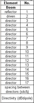
45 Optimized Uncompensated Lengths (in λ) of Parasitic Elements for Six Yagi-Uda Antennas Length of Yagi-Uda (λ) Element No reflector driven director director director Conditions: (a) element diameter: 0.001λ < d < 0.04λ (e.g. d = λ) (b) reflector-driven element spacing, s 12 = 0.2λ (c) driven element is a λ/2 folded dipole dbi = db dipole db [Source: P.P Viezbicke, Yagi Antenna Design, NBS Technical Note 688] 45 director director director director director director director director director director director director spacing between directors (sik/λ) Directivity (dbdipole) Design curve (see Figure 10.27) (A) (B) (B) (C) (B) (D) 45
46 Element Length Adjustments For element diameter not equal to λ, the lengths of the reflector and directors should be adjusted according to the design curves published in [PP Viezbicke, Yagi Antenna Design, NBS Tech. Note 688, US Department of Commerce- National Bureau of Standards, October The same graph can also be found in CA Balanis, Antenna Theory, Wiley Similarly, the lengths of the reflector and directors should be adjusted if a metallic boom is used, according to the design curve published by NBS Tech. Note 688 above
47 Yagi Design Example Design Specifications: Frequency range = 434 MHz Directivity = 10 dbi (or 7.85 db dipole) Input impedance = 50 Ω Diameter of elements = 8 mm Design with Yagi Antenna Design spreadsheet Simulation (e.g., with MININEC) Construction & Testing 47 47

48 Yagi Design Spreadsheet 48 48
49 A Simple Method to Design a 3-Element Yagi Antenna Rules used in this design method: Length of driven element, L drv = 0.95 * λ/2 Length of reflector, L ref = 1.15 * L drv Length of director, L dir = 0.90 * L drv Element spacing, s = 0.15 * λ For a given design frequency, the wavelength λand the above four parameters are calculated. Expert MININEC simulation is used to determine the minimum- VSWR (or S 11 ) frequency. The frequency calculated by the simulation is used to scale the above four parameters to the design frequency. Another Expert MININEC simulation is carried out to confirm the design. Usually, only one iteration is required

50 Example of a 3-Element Yagi Antenna Design The desired design frequency is MHz. The diameter of all antenna elements is 1.60 mm
51 Example of a 3-Element Yagi Antenna Design The desired design frequency was 434 MHz. The minimum-vswr (or minimum-s 11 ) frequency was found to be 421 MHz. This value was entered into the spreadsheet. Adjusted values of the three antenna elements and spacing were calculated in the "1st Iteration (mm)" columns. A second run of the Expert MININEC simulation confirmed the desired design frequency of 434 MHz was obtained

52 Coordinates of 3-Element Yagi The desired design frequency was 434 MHz
53 S 11, VSWR, and Impedance of 3- Element Yagi The desired design frequency was 434 MHz. VSWR=3 460 MHz 434 MHz 410 MHz 53 53

54 Radiation Pattern of 3-Element θ Yagi E-plane H-plane φ 54 54
Broadband Antenna. Broadband Antenna. Chapter 4
 1 Chapter 4 Learning Outcome At the end of this chapter student should able to: To design and evaluate various antenna to meet application requirements for Loops antenna Helix antenna Yagi Uda antenna
Travelling Wave, Broadband, and Frequency Independent Antennas. EE-4382/ Antenna Engineering
 Travelling Wave, Broadband, and Frequency Independent Antennas EE-4382/5306 - Antenna Engineering Outline Traveling Wave Antennas Introduction Traveling Wave Antennas: Long Wire, V Antenna, Rhombic Antenna
Half-Wave Dipole. Radiation Resistance. Antenna Efficiency
 Antennas Simple Antennas Isotropic radiator is the simplest antenna mathematically Radiates all the power supplied to it, equally in all directions Theoretical only, can t be built Useful as a reference:
Antenna Theory and Design
 Antenna Theory and Design Antenna Theory and Design Associate Professor: WANG Junjun 王珺珺 School of Electronic and Information Engineering, Beihang University wangjunjun@buaa.edu.cn 13426405497 Chapter
Traveling Wave Antennas
 Traveling Wave Antennas Antennas with open-ended wires where the current must go to zero (dipoles, monopoles, etc.) can be characterized as standing wave antennas or resonant antennas. The current on these
Miscellaneous Topics. Folded dipole antenna Special antennas. Other antennas Feed Lines. Yagi-Uda antenna Broadband antenna Log-periodic antenna
 Folded dipole antenna Special antennas Yagi-Uda antenna Broadband antenna Log-periodic antenna Other antennas Feed Lines Miscellaneous Topics 1 Folded Dipole Half-wavelength dipoles have impedance 73+j42.5
Analysis of Radiation Pattern of a Log Periodic Dipole Antenna in VHF Frequency
 Analysis of Radiation Pattern of a Log Periodic Dipole Antenna in VHF Frequency A.B.Bhattacharya 1, K. Roy 2, A. Nag 3, K. Acharjee 3, K. Chatterjee 3, S. Banerjee 3, R. Ram 3 Department of Physics, University
Resonant Antennas: Wires and Patches
 Resonant Antennas: Wires and Patches Dipole Antennas Antenna 48 Current distribution approximation Un-normalized pattern: and Antenna 49 Radiating power: For half-wave dipole and,, or at exact resonance.
CHAPTER 8 ANTENNAS 1
 CHAPTER 8 ANTENNAS 1 2 Antennas A good antenna works A bad antenna is a waste of time & money Antenna systems can be very inexpensive and simple They can also be very expensive 3 Antenna Considerations
Chapter 6 Antenna Basics. Dipoles, Ground-planes, and Wires Directional Antennas Feed Lines
 Chapter 6 Antenna Basics Dipoles, Ground-planes, and Wires Directional Antennas Feed Lines Some General Rules Bigger is better. (Most of the time) Higher is better. (Most of the time) Lower SWR is better.
UNIT Write short notes on travelling wave antenna? Ans: Travelling Wave Antenna
 UNIT 4 1. Write short notes on travelling wave antenna? Travelling Wave Antenna Travelling wave or non-resonant or aperiodic antennas are those antennas in which there is no reflected wave i.e., standing
DESIGN, DEVELOPMENT AND PERFORMANCE ANALYSIS OF RECONFIGURABLE LOG PERIODIC ANTENNA FOR RF FRONT-END MULTI STANDARD TRANSCEIVER
 International Journal of Electronics and Communication Engineering and Technology (IJECET) Volume 9, Issue 6, November-December2018, pp. 30 37, Article ID: IJECET_09_06_004 Available online at http://www.iaeme.com/ijecet/issues.asp?jtype=ijecet&vtype=9&itype=6
Chapter 5. Array of Star Spirals
 Chapter 5. Array of Star Spirals The star spiral was introduced in the previous chapter and it compared well with the circular Archimedean spiral. This chapter will examine the star spiral in an array
ANTENNA THEORY. Analysis and Design. CONSTANTINE A. BALANIS Arizona State University. JOHN WILEY & SONS New York Chichester Brisbane Toronto Singapore
 ANTENNA THEORY Analysis and Design CONSTANTINE A. BALANIS Arizona State University JOHN WILEY & SONS New York Chichester Brisbane Toronto Singapore Contents Preface xv Chapter 1 Antennas 1 1.1 Introduction
BHARATHIDASAN ENGINEERING COLLEGE NATTARAMPALLI Frequently Asked Questions (FAQ) Unit 1
 Unit 1") BHARATHIDASAN ENGINEERING COLLEGE NATTARAMPALLI 635854 Frequently Asked Questions (FAQ) Unit 1 Degree / Branch : B.E / ECE Sem / Year : 3 rd / 6 th Sub Name : Antennas & Wave Propagation Sub Code : EC6602
BHARATHIDASAN ENGINEERING COLLEGE NATTARAMPALLI 635854 Frequently Asked Questions (FAQ) Unit 1 Degree / Branch : B.E / ECE Sem / Year : 3 rd / 6 th Sub Name : Antennas & Wave Propagation Sub Code : EC6602
American International Journal of Research in Science, Technology, Engineering & Mathematics
 American International Journal of Research in Science, Technology, Engineering & Mathematics Available online at http://www.iasir.net ISSN (Print): 2328-3491, ISSN (Online): 2328-3580, ISSN (CD-ROM): 2328-3629
Yagi beam antennas CHAPTER 10 COMPOSITION OF A BEAM ANTENNA _
 CHAPTER 10 Yagi beam antennas The Yagi beam antenna (more correctly, the Yagi Uda antenna, after both of the designers of Tohoku University in Japan 1926) is unidirectional. It can be vertically polarized
EC ANTENNA AND WAVE PROPAGATION
 EC6602 - ANTENNA AND WAVE PROPAGATION FUNDAMENTALS PART-B QUESTION BANK UNIT 1 1. Define the following parameters w.r.t antenna: i. Radiation resistance. ii. Beam area. iii. Radiation intensity. iv. Directivity.
General License Class Chapter 6 - Antennas. Bob KA9BHD Eric K9VIC
 General License Class Chapter 6 - Antennas Bob KA9BHD Eric K9VIC Learning Objectives Teach you enough to get all the antenna questions right during the VE Session Learn a few things from you about antennas
RADIATION PATTERNS. The half-power (-3 db) beamwidth is a measure of the directivity of the antenna.
 beamwidth is a measure of the directivity of the antenna.") RADIATION PATTERNS The radiation pattern is a graphical depiction of the relative field strength transmitted from or received by the antenna. Antenna radiation patterns are taken at one frequency, one
RADIATION PATTERNS The radiation pattern is a graphical depiction of the relative field strength transmitted from or received by the antenna. Antenna radiation patterns are taken at one frequency, one
Notes 21 Introduction to Antennas
 ECE 3317 Applied Electromagnetic Waves Prof. David R. Jackson Fall 018 Notes 1 Introduction to Antennas 1 Introduction to Antennas Antennas An antenna is a device that is used to transmit and/or receive
Milton Keynes Amateur Radio Society (MKARS)
") Milton Keynes Amateur Radio Society (MKARS) Intermediate Licence Course Feeders Antennas Matching (Worksheets 31, 32 & 33) MKARS Intermediate Licence Course - Worksheet 31 32 33 Antennas Feeders Matching
Milton Keynes Amateur Radio Society (MKARS) Intermediate Licence Course Feeders Antennas Matching (Worksheets 31, 32 & 33) MKARS Intermediate Licence Course - Worksheet 31 32 33 Antennas Feeders Matching
ANTENNAS. I will mostly be talking about transmission. Keep in mind though, whatever is said about transmission is true of reception.
 Reading 37 Ron Bertrand VK2DQ http://www.radioelectronicschool.com ANTENNAS The purpose of an antenna is to receive and/or transmit electromagnetic radiation. When the antenna is not connected directly
DESIGN AND SIMULATION OF CYLINDRICAL AND SHEET CORNER REFLECTOR YAGI UDA ANTENNAS FOR AMATEUR RADIO APPLICATION
 DESIGN AND SIMULATION OF CYLINDRICAL AND SHEET CORNER REFLECTOR YAGI UDA ANTENNAS FOR AMATEUR RADIO APPLICATION Akella Jharesh, K. Ch. Sri Kavya and Sarat K. Kotamraju Department of Electronics and Communication
HHTEHHH THEORY ANALYSIS AND DESIGN. CONSTANTINE A. BALANIS Arizona State University
 HHTEHHH THEORY ANALYSIS AND DESIGN CONSTANTINE A. BALANIS Arizona State University JOHN WILEY & SONS, INC. New York Chichester Brisbane Toronto Singapore Contents Preface V CHAPTER 1 ANTENNAS 1.1 Introduction
COUPLED SECTORIAL LOOP ANTENNA (CSLA) FOR ULTRA-WIDEBAND APPLICATIONS *
 FOR ULTRA-WIDEBAND APPLICATIONS *") COUPLED SECTORIAL LOOP ANTENNA (CSLA) FOR ULTRA-WIDEBAND APPLICATIONS * Nader Behdad, and Kamal Sarabandi Department of Electrical Engineering and Computer Science University of Michigan, Ann Arbor, MI,
COUPLED SECTORIAL LOOP ANTENNA (CSLA) FOR ULTRA-WIDEBAND APPLICATIONS * Nader Behdad, and Kamal Sarabandi Department of Electrical Engineering and Computer Science University of Michigan, Ann Arbor, MI,
4/29/2012. General Class Element 3 Course Presentation. Ant Antennas as. Subelement G9. 4 Exam Questions, 4 Groups
 General Class Element 3 Course Presentation ti ELEMENT 3 SUB ELEMENTS General Licensing Class Subelement G9 Antennas and Feedlines 4 Exam Questions, 4 Groups G1 Commission s Rules G2 Operating Procedures
Newsletter 3.1. Antenna Magus version 3.1 released! New antennas in the database. Square pin-fed septum horn. July 2011
 Newsletter 3.1 July 2011 Antenna Magus version 3.1 released! Antenna Magus 3.0 was such a feature laden release that not all of the new features could be mentioned in the newsletter, so we decided to rather
1. Explain the basic geometry and elements of Yagi-Uda antenna.
 Benha University Faculty of Engineering- Shoubra Electrical Engineering Department Fourth Year (Communications & Electronics) Final-Term Exam Date: Tuesday 10/5/2016 ECE 424: Lab (4) Duration : 2 Hrs Answer
4 Antennas as an essential part of any radio station
 4 Antennas as an essential part of any radio station 4.1 Choosing an antenna Communicators quickly learn two antenna truths: Any antenna is better than no antenna. Time, effort and money invested in the
Large Loop Antennas. Special thanks to graduate students of ECSE 593 class, Winter 2007: Yasha Khatamian, Lin Han, Ruiming Chen
 Large Loop Antennas Special thanks to graduate students of ECSE 593 class, Winter 2007: Yasha Khatamian, Lin Han, Ruiming Chen McGill University, ECSE 405 Antennas, Fall 2009, Prof. M. Popovic 1. History
A LABORATORY COURSE ON ANTENNA MEASUREMENT
 A LABORATORY COURSE ON ANTENNA MEASUREMENT Samuel Parker Raytheon Systems Company, 2000 East Imperial Highway RE/R02/V509, El Segundo, CA 90245 Dean Arakaki Electrical Engineering Department, California
Antennas 101 Don t Be a 0.97 db Weakling! Ward Silver NØAX
 Antennas 101 Don t Be a 0.97 db Weakling! Ward Silver NØAX Overview Antennas 101 2 Overview Basic Antennas: Ground Plane / Dipole How Gain and Nulls are Formed How Phased Arrays Work How Yagis Work (simplified)
Fundamentals of Antennas. Prof. Ely Levine
 Fundamentals of Antennas Prof. Ely Levine levineel@zahav.net.il 1 Chapter 3 Wire Antennas 2 Types of Antennas 3 Isotropic Antenna Isotropic radiator is the simplest antenna mathematically Radiates all
SI TECHNICAL 2018 UNIT IV QUESTION BANK
 SI TECHNICAL 2018 UNIT IV QUESTION BANK 1. In what range of frequencies are most omnidirectional horizontally polarized antennas used? A. VHF, UHF B. VLF, LF C. SH, EHF D. MF, HF 2. If the current ratios
Antenna Fundamentals. Microwave Engineering EE 172. Dr. Ray Kwok
 Antenna Fundamentals Microwave Engineering EE 172 Dr. Ray Kwok Reference Antenna Theory and Design Warran Stutzman, Gary Thiele, Wiley & Sons (1981) Microstrip Antennas Bahl & Bhartia, Artech House (1980)
YAGI-UDA DESIGN OF U.H.F BAND AERIAL TO SUIT LOCAL TV STATIONS
 YAGI-UDA DESIGN OF U.H.F BAND AERIAL TO SUIT LOCAL TV STATIONS PROJECT INDEX: PRJ 079 Presented By: GITAU SIMON WAWERU F17/8261/2004 Supervisor: Mr. S.L OGABA Examiner: Mr. OMBURA Objective The main objective
Yagi-Uda (Beam) Antenna
 Antenna") Yagi-Uda (Beam) Antenna Gary A. Thiele KD8ZWS (Ex W8RBW) Co-author of Antenna Theory & Design John Wiley & Sons, 1981, 1998, 2013 Yagi-Uda (Beam) Antennas Outline Preliminary Remarks Part I Brief history
Yagi-Uda (Beam) Antenna Gary A. Thiele KD8ZWS (Ex W8RBW) Co-author of Antenna Theory & Design John Wiley & Sons, 1981, 1998, 2013 Yagi-Uda (Beam) Antennas Outline Preliminary Remarks Part I Brief history
DESIGN CONSIDERATION OF ARRAYS FOR THE STUDIES OF RADIATION PATTERN OF LOG PERIODIC DIPOLE ARRAY ANTENNA AT DIFFERENT FREQUENCIES
 DESIGN CONSIDERATION OF ARRAYS FOR THE STUDIES OF RADIATION PATTERN OF LOG PERIODIC DIPOLE ARRAY ANTENNA AT DIFFERENT FREQUENCIES 1 Atanu Nag, 2 Kanchan Acharjee, 3 Kausturi Chatterjee, 4 Swastika Banerjee
Antennas Demystified Antennas in Emergency Communications. Scott Honaker N7SS
 Antennas Demystified Antennas in Emergency Communications Scott Honaker N7SS Importance of Antennas Antennas are more important than the radio A $5000 TV with rabbit ears will have a lousy picture Antennas
Dipole Antennas. Prof. Girish Kumar Electrical Engineering Department, IIT Bombay. (022)
") Dipole Antennas Prof. Girish Kumar Electrical Engineering Department, IIT Bombay gkumar@ee.iitb.ac.in (022) 2576 7436 Infinitesimal Dipole An infinitesimally small current element is called the Hertz Dipole
Dipole Antennas Prof. Girish Kumar Electrical Engineering Department, IIT Bombay gkumar@ee.iitb.ac.in (022) 2576 7436 Infinitesimal Dipole An infinitesimally small current element is called the Hertz Dipole
CHAPTER 5 THEORY AND TYPES OF ANTENNAS. 5.1 Introduction
 CHAPTER 5 THEORY AND TYPES OF ANTENNAS 5.1 Introduction Antenna is an integral part of wireless communication systems, considered as an interface between transmission line and free space [16]. Antenna
Antenna Technology Bootcamp. NTA Show 2017 Denver, CO
 Antenna Technology Bootcamp NTA Show 2017 Denver, CO Review: How a slot antenna works The slot antenna is a TEM-Mode coaxial structure. Coupling structures inside the pylon will distort and couple to the
Loop and Slot Antennas
 Loop and Slot Antennas Prof. Girish Kumar Electrical Engineering Department, IIT Bombay gkumar@ee.iitb.ac.in (022) 2576 7436 Loop Antenna Loop antennas can have circular, rectangular, triangular or any
Dr. John S. Seybold. November 9, IEEE Melbourne COM/SP AP/MTT Chapters
 Antennas Dr. John S. Seybold November 9, 004 IEEE Melbourne COM/SP AP/MTT Chapters Introduction The antenna is the air interface of a communication system An antenna is an electrical conductor or system
HIGH GAIN KOCH FRACTAL DIPOLE YAGI-UDA ANTENNA FOR S AND X BAND APPLICATION
 HIGH GAIN KOCH FRACTAL DIPOLE YAGI-UDA ANTENNA FOR S AND X BAND APPLICATION Rajeev Kumar 1, R Radhakrishnan 2 1,2 Department of Theoretical Physics, University of Madras, (India) ABSTRACT In this study,
Novel Broadband and Multi-band Antennas for Satellite and Wireless Applications
 Novel Broadband and Multi-band Antennas for Satellite and Wireless Applications The objective of our research is to develop novel antenna structures for broadband and/or multi-band satellite and wireless
Microstrip Antennas Integrated with Horn Antennas
 53 Microstrip Antennas Integrated with Horn Antennas Girish Kumar *1, K. P. Ray 2 and Amit A. Deshmukh 1 1. Department of Electrical Engineering, I.I.T. Bombay, Powai, Mumbai 400 076, India Phone: 91 22
Monopole Antennas. Prof. Girish Kumar Electrical Engineering Department, IIT Bombay. (022)
") Monopole Antennas Prof. Girish Kumar Electrical Engineering Department, IIT Bombay gkumar@ee.iitb.ac.in (022) 2576 7436 Monopole Antenna on Infinite Ground Plane Quarter-wavelength monopole Antenna on
Monopole Antennas Prof. Girish Kumar Electrical Engineering Department, IIT Bombay gkumar@ee.iitb.ac.in (022) 2576 7436 Monopole Antenna on Infinite Ground Plane Quarter-wavelength monopole Antenna on
DESIGN OF PASSIVE RETRANSMITTING SYSTEM
 76 DESIGN OF PASSIVE RETRANSMITTING SYSTEM FOR CELLULAR COMMUNICATION Juliane Iten Chaves, Anton Gora Junior, and José Ricardo Descardeci Department of Electrical Engineering, Federal University of Parana-UFPR
Antennas Prof. Girish Kumar Department of Electrical Engineering Indian Institute of Technology, Bombay. Module 2 Lecture - 10 Dipole Antennas-III
 Antennas Prof. Girish Kumar Department of Electrical Engineering Indian Institute of Technology, Bombay Module 2 Lecture - 10 Dipole Antennas-III Hello, and welcome to todays lecture on Dipole Antenna.
S.R.M. Institute of Science & Technology Deemed University School of Electronics & Communication Engineering
 S.R.M. Institute of Science & Technology Deemed University School of Electronics & Communication Engineering Question Bank Subject Code : EC401 Subject Name : Antennas and Wave Propagation Year & Sem :
KINGS COLLEGE OF ENGINEERING. DEPARTMENT OF ELECTRONICS AND COMMUNICATION ENGINEERING Academic Year (Even Sem) QUESTION BANK (AUTT-R2008)
 QUESTION BANK (AUTT-R2008)") KINGS COLLEGE OF ENGINEERING DEPARTMENT OF ELECTRONICS AND COMMUNICATION ENGINEERING Academic Year 2012-2013(Even Sem) QUESTION BANK (AUTT-R2008) SUBJECT CODE /NAME: EC 1352 / ANTENNEA AND WAVE PROPAGATION
KINGS COLLEGE OF ENGINEERING DEPARTMENT OF ELECTRONICS AND COMMUNICATION ENGINEERING Academic Year 2012-2013(Even Sem) QUESTION BANK (AUTT-R2008) SUBJECT CODE /NAME: EC 1352 / ANTENNEA AND WAVE PROPAGATION
CHAPTER 5 ANALYSIS OF MICROSTRIP PATCH ANTENNA USING STACKED CONFIGURATION
 1 CHAPTER 5 ANALYSIS OF MICROSTRIP PATCH ANTENNA USING STACKED CONFIGURATION 5.1 INTRODUCTION Rectangular microstrip patch with U shaped slotted patch is stacked, Hexagonal shaped patch with meander patch
Coaxial Cable Feeder Influence on Four Stacked Yagi Antennas Array Dragoslav Dobričić, YU1AW
 Coaxial Cable Feeder Influence on Four Stacked Yagi Antennas Array Dragoslav Dobričić, YU1AW dragan@antennex.com Introduction Aprevious article series consisted of two parts [1, 2] showing the results
ELEC 477/677L Wireless System Design Lab Spring 2014
 ELEC 477/677L Wireless System Design Lab Spring 2014 Lab #5: Yagi-Uda Antenna Design Using EZNEC Introduction There are many situations, such as in point-to-point communication, where highly directional
Cray Valley Radio Society. Real Life Wire Antennas
 Cray Valley Radio Society Real Life Wire Antennas 1 The basic dipole The size of an antenna is determined by the wavelength of operation In free space: ~3x10 8 m/s Frequency x Wavelength = Speed of Light,
Design of a Novel Compact Cup Feed for Parabolic Reflector Antennas
 Progress In Electromagnetics Research Letters, Vol. 64, 81 86, 2016 Design of a Novel Compact Cup Feed for Parabolic Reflector Antennas Amir Moallemizadeh 1,R.Saraf-Shirazi 2, and Mohammad Bod 2, * Abstract
INSTITUTE OF AERONAUTICAL ENGINEERING Dundigal, Hyderabad ELECTRONICS AND COMMUNIACTION ENGINEERING QUESTION BANK
 INSTITUTE OF AERONAUTICAL ENGINEERING Dundigal, Hyderabad - 500 04 ELECTRONICS AND COMMUNIACTION ENGINEERING QUESTION BANK Course Name : Antennas and Wave Propagation (AWP) Course Code : A50418 Class :
R. Zhang, G. Fu, Z.-Y. Zhang, and Q.-X. Wang Key Laboratory of Antennas and Microwave Technology Xidian University, Xi an, Shaanxi , China
 Progress In Electromagnetics Research Letters, Vol. 2, 137 145, 211 A WIDEBAND PLANAR DIPOLE ANTENNA WITH PARASITIC PATCHES R. Zhang, G. Fu, Z.-Y. Zhang, and Q.-X. Wang Key Laboratory of Antennas and Microwave
KINGS COLLEGE OF ENGINEERING DEPARTMENT OF ELECTRONICS AND COMMUNICATION ENGINEERING QUESTION BANK
 KINGS COLLEGE OF ENGINEERING DEPARTMENT OF ELECTRONICS AND COMMUNICATION ENGINEERING QUESTION BANK SUB.NAME : ANTENNAS & WAVE PROPAGATION SUB CODE : EC 1352 YEAR : III SEMESTER : VI UNIT I: ANTENNA FUNDAMENTALS
Intermediate Course (5) Antennas and Feeders
 Antennas and Feeders") Intermediate Course (5) Antennas and Feeders 1 System Transmitter 50 Ohms Output Standing Wave Ratio Meter Antenna Matching Unit Feeder Antenna Receiver 2 Feeders Feeder types: Coaxial, Twin Conductors
Intermediate Course (5) Antennas and Feeders 1 System Transmitter 50 Ohms Output Standing Wave Ratio Meter Antenna Matching Unit Feeder Antenna Receiver 2 Feeders Feeder types: Coaxial, Twin Conductors
What does reciprocity mean
 Antennas Definition of antenna: A device for converting electromagnetic radiation in space into electrical currents in conductors or vice-versa. Radio telescopes are antennas Reciprocity says we can treat
ANTENNA TUTORIAL 1. INTRODUCTION 2. CLASSIFICATION OF ANTENNAS
 ANTENNA TUTORIAL Phumzile Malindi, Department of Electrical Engineering, Walter Sisulu University, 19 Manchester Road, Chiselhurst, EAST LONDON, 501, South Africa pmalindi@webmail.co.za 1. INTRODUCTION
Newsletter 2.3. Antenna Magus version 2.3 released! New antennas in Version 2.3. Potter horn. Circularly polarised rectangular-biquad antenna
 Newsletter 2.3 October 2010 Antenna Magus version 2.3 released! An update to Antenna Magus, version 2.3, is now available for download. This update features 10 new antennas, as opposed to the usual 6.
Ultrawideband (UWB) and Reconfigurable Antennas - New Concepts For Conformal Load Bearing Antenna Structures (CLAS)
 and Reconfigurable Antennas - New Concepts For Conformal Load Bearing Antenna Structures (CLAS)") University of South Carolina Scholar Commons Theses and Dissertations 1-1-2013 Ultrawideband (UWB) and Reconfigurable Antennas - New Concepts For Conformal Load Bearing Antenna Structures (CLAS) Nicholas
University of South Carolina Scholar Commons Theses and Dissertations 1-1-2013 Ultrawideband (UWB) and Reconfigurable Antennas - New Concepts For Conformal Load Bearing Antenna Structures (CLAS) Nicholas
Antenna Trainer EAN. Technical Teaching Equipment INTRODUCTION
 Antenna Trainer EAN Technical Teaching Equipment Products Products range Units 3.-Communications INTRODUCTION Antennas are the main element of aerial communications. They are the transition between a transmission
Welcome to AntennaSelect Volume 10 May Optimizing VHF (Band III) Batwing antennas - Part 2
 Batwing antennas - Part 2") Welcome to AntennaSelect Volume 10 May 2014 Welcome to Volume 10 of our newsletter, AntennaSelect TM. Each month we will be giving you an under the radome look at antenna and RF technology. If there are
Welcome to AntennaSelect Volume 10 May 2014 Welcome to Volume 10 of our newsletter, AntennaSelect TM. Each month we will be giving you an under the radome look at antenna and RF technology. If there are
A Wideband Dual-polarized Modified Bowtie Antenna for 2G/3G/LTE Base-station Applications
 Progress In Electromagnetics Research Letters, Vol. 61, 131 137, 2016 A Wideband Dual-polarized Modified Bowtie Antenna for 2G/3G/LTE Base-station Applications Zhao Yang *, Cilei Zhang, Yingzeng Yin, and
High Performance System-on-Package Integrated Yagi-Uda Antennas for W-band Applications and mm-wave Ultra-Wideband Data Links
 High Performance System-on-Package Integrated Yagi-Uda Antennas for W-band Applications and mm-wave Ultra-Wideband Data Links B. Pan, G. DeJean, J. Papapolymerou, M. M Tentzeris, Y. Yoon and M. G. Allen
Broadband Circular Polarized Antenna Loaded with AMC Structure
 Progress In Electromagnetics Research Letters, Vol. 76, 113 119, 2018 Broadband Circular Polarized Antenna Loaded with AMC Structure Yi Ren, Xiaofei Guo *,andchaoyili Abstract In this paper, a novel broadband
EMG4066:Antennas and Propagation Exp 1:ANTENNAS MMU:FOE. To study the radiation pattern characteristics of various types of antennas.
 OBJECTIVES To study the radiation pattern characteristics of various types of antennas. APPARATUS Microwave Source Rotating Antenna Platform Measurement Interface Transmitting Horn Antenna Dipole and Yagi
WIDE BEAMWIDTH QUADIFILAR HELIX ANTENNA WITH CROSS DIPOLES
 Progress In Electromagnetics Research C, Vol. 40, 229 242, 2013 WIDE BEAMWIDTH QUADIFILAR HELIX ANTENNA WITH CROSS DIPOLES Wei Xin Lin and Qing Xin Chu * School of Electronic and Information Engineering,
Design of Low-Index Metamaterial Lens Used for Wideband Circular Polarization Antenna
 Progress In Electromagnetics Research Letters, Vol. 68, 93 98, 2017 Design of Low-Index Metamaterial Lens Used for Wideband Circular Polarization Antenna Yong Wang and Yanlin Zou * Abstract A novel low-index
Chapter 7 - Experimental Verification
 Chapter 7 - Experimental Verification 7.1 Introduction This chapter details the results of measurements from several experimental prototypes of Stub Loaded Helix antennas that were built and tested. Due
Coming next: Wireless antennas for beginners
 Coming next: Wireless antennas for beginners In other rooms: Logbook of the World (Sussex Suite) SO2R contest operation (Stable Suite) Wires for your wireless: Simple wire antennas for beginners dominic
SIMULATIVE ANALYSIS OF DISCONE ANTENNA FOR 2.44 GHZ REGIME USING ANTENNA MAGUS
 SIMULATIVE ANALYSIS OF DISCONE ANTENNA FOR 2.44 GHZ REGIME USING ANTENNA MAGUS Amandeep Singh, Asstt. Prof. in ECE Deptt, DAV institute of Engineering & Technology, Jalandhar Neeru Malhotra Associate Professor
BROADBAND SERIES-FED DIPOLE PAIR ANTENNA WITH PARASITIC STRIP PAIR DIRECTOR
 Progress In Electromagnetics Research C, Vol. 45, 1 13, 2013 BROADBAND SERIES-FED DIPOLE PAIR ANTENNA WITH PARASITIC STRIP PAIR DIRECTOR Junho Yeo 1, Jong-Ig Lee 2, *, and Jin-Taek Park 3 1 School of Computer
Development of a noval Switched Beam Antenna for Communications
 Master Thesis Presentation Development of a noval Switched Beam Antenna for Communications By Ashraf Abuelhaija Supervised by Prof. Dr.-Ing. Klaus Solbach Institute of Microwave and RF Technology Department
Antennas and Propagation Chapters T4, G7, G8 Antenna Fundamentals, More Antenna Types, Feed lines and Measurements, Propagation
 Antennas and Propagation Chapters T4, G7, G8 Antenna Fundamentals, More Antenna Types, Feed lines and Measurements, Propagation =============================================================== Antenna Fundamentals
Yagi Antenna Tutorial. Copyright K7JLT 1
 Yagi Antenna Tutorial Copyright K7JLT Yagi: The Man & Developments In the 920 s two Japanese electrical engineers, Hidetsugu Yagi and Shintaro Uda at Tohoku University in Sendai Japan, investigated ways
An Introduction to Antennas
 May 11, 010 An Introduction to Antennas 1 Outline Antenna definition Main parameters of an antenna Types of antennas Antenna radiation (oynting vector) Radiation pattern Far-field distance, directivity,
You will need the following pieces of equipment to complete this experiment: Wilkinson power divider (3-port board with oval-shaped trace on it)
") UNIVERSITY OF TORONTO FACULTY OF APPLIED SCIENCE AND ENGINEERING The Edward S. Rogers Sr. Department of Electrical and Computer Engineering ECE422H1S: RADIO AND MICROWAVE WIRELESS SYSTEMS EXPERIMENT 1:
UNIVERSITY OF TORONTO FACULTY OF APPLIED SCIENCE AND ENGINEERING The Edward S. Rogers Sr. Department of Electrical and Computer Engineering ECE422H1S: RADIO AND MICROWAVE WIRELESS SYSTEMS EXPERIMENT 1:
Newsletter 4.4. Antenna Magus version 4.4 released! Array synthesis reflective ground plane addition. July 2013
 Newsletter 4.4 July 2013 Antenna Magus version 4.4 released! We are pleased to announce the new release of Antenna Magus Version 4.4. This release sees the addition of 5 new antennas: Horn-fed truncated
COMPUTED ENVELOPE LINEARITY OF SEVERAL FM BROADCAST ANTENNA ARRAYS
 COMPUTED ENVELOPE LINEARITY OF SEVERAL FM BROADCAST ANTENNA ARRAYS J. DANE JUBERA JAMPRO ANTENNAS, INC PRESENTED AT THE 28 NAB ENGINEERING CONFERENCE APRIL 16, 28 LAS VEGAS, NV COMPUTED ENVELOPE LINEARITY
Antenna Fundamentals Basics antenna theory and concepts
 Antenna Fundamentals Basics antenna theory and concepts M. Haridim Brno University of Technology, Brno February 2017 1 Topics What is antenna Antenna types Antenna parameters: radiation pattern, directivity,
A Low-Profile Cavity-Backed Dual-Polarized Spiral Antenna Array
 A Low-Profile Cavity-Backed Dual-Polarized Spiral Antenna Array Mohammed Serhir, Régis Guinvarc H To cite this version: Mohammed Serhir, Régis Guinvarc H. A Low-Profile Cavity-Backed Dual-Polarized Spiral
Basic Wire Antennas. Part II: Loops and Verticals
 Basic Wire Antennas Part II: Loops and Verticals A loop antenna is composed of a single loop of wire, greater than a half wavelength long. The loop does not have to be any particular shape. RF power can
Introduction to Radar Systems. Radar Antennas. MIT Lincoln Laboratory. Radar Antennas - 1 PRH 6/18/02
 Introduction to Radar Systems Radar Antennas Radar Antennas - 1 Disclaimer of Endorsement and Liability The video courseware and accompanying viewgraphs presented on this server were prepared as an account
Antennas & wave Propagation ASSIGNMENT-I
 Shri Vishnu Engineering College for Women :: Bhimavaram Department of Electronics & Communication Engineering Antennas & wave Propagation 1. Define the terms: i. Antenna Aperture ii. Beam Width iii. Aperture
DESIGN OF A NOVEL WIDEBAND LOOP ANTENNA WITH PARASITIC RESONATORS. Microwaves, Xidian University, Xi an, Shaanxi, China
 Progress In Electromagnetics Research Letters, Vol. 37, 47 54, 2013 DESIGN OF A NOVEL WIDEBAND LOOP ANTENNA WITH PARASITIC RESONATORS Shoutao Fan 1, *, Shufeng Zheng 1, Yuanming Cai 1, Yingzeng Yin 1,
Coupled Sectorial Loop Antenna (CSLA) for Ultra Wideband Applications
 for Ultra Wideband Applications") Coupled Sectorial Loop Antenna (CSLA) for Ultra Wideband Applications N. Behdad and K. Sarabandi Presented by Nader Behdad at Antenna Application Symposium, Monticello, IL, Sep 2004 Email: behdad@ieee.org
Coupled Sectorial Loop Antenna (CSLA) for Ultra Wideband Applications N. Behdad and K. Sarabandi Presented by Nader Behdad at Antenna Application Symposium, Monticello, IL, Sep 2004 Email: behdad@ieee.org
Practical Antennas and. Tuesday, March 4, 14
 Practical Antennas and Transmission Lines Goals Antennas are the interface between guided waves (from a cable) and unguided waves (in space). To understand the various properties of antennas, so as to
Designing and building a Yagi-Uda Antenna Array
 2015; 2(2): 296-301 IJMRD 2015; 2(2): 296-301 www.allsubjectjournal.com Received: 17-12-2014 Accepted: 26-01-2015 E-ISSN: 2349-4182 P-ISSN: 2349-5979 Impact factor: 3.762 Abdullah Alshahrani School of
A Broadband Omnidirectional Antenna Array for Base Station
 Progress In Electromagnetics Research C, Vol. 54, 95 101, 2014 A Broadband Omnidirectional Antenna Array for Base Station Bo Wang 1, *, Fushun Zhang 1,LiJiang 1, Qichang Li 2, and Jian Ren 1 Abstract A
International Journal of Scientific & Engineering Research, Volume 4, Issue 6, June ISSN
 International Journal of Scientific & Engineering Research, Volume 4, Issue 6, June-2013 235 Design of Quadrifilar Helical Antenna For S-Band Applications Sonia Sharma, Jagmehender Sheoran, Om Prakash
PAPER PRESENTATION ON ANTENNA AND WAVE PROPAGATION COMPARISON OF FRACTAL ANTENNA AND YAGI-UDA ANTENNA
 ISSN 2320-9119 74 International Journal of Advance Research, IJOAR.org Volume 1, Issue 3, March 2013, Online: ISSN 2320-9199 PAPER PRESENTATION ON ANTENNA AND WAVE PROPAGATION COMPARISON OF FRACTAL ANTENNA
Frequency Reconfigurable Log Periodic Microstrip Dipole Antenna Array for Wideband Applications
 IJIRST International Journal for Innovative Research in Science & Technology Volume 4 Issue 3 August 2017 ISSN (online): 2349-6010 Frequency Reconfigurable Log Periodic Microstrip Dipole Antenna Array
Antenna Theory and Design
 Antenna Theory and Design SECOND EDITION Warren L. Stutzman Gary A. Thiele WILEY Contents Chapter 1 Antenna Fundamentals and Definitions 1 1.1 Introduction 1 1.2 How Antennas Radiate 4 1.3 Overview of
UNIT - IV SPECIAL ANTENNAS AND ANTENNA MEASUREMENTS. B.Hemalatha - AP/ECE
 UNIT - IV SPECIAL ANTENNAS AND ANTENNA MEASUREMENTS 1 Elementary Antennas low cost flexible solutions Transmission Line Antenna R=Z 0 Long Wire Antenna effective wideband antenna length l = several wavelengths