Utilizing Reverberation Chambers as a Versatile Test Environment for Assessing the Performance of Components and Systems
|
|
|
- Marvin Bishop
- 5 years ago
- Views:
Transcription

1 Utilizing Reverberation Chambers as a Versatile Test Environment for Assessing the Performance of Components and Systems Dennis Lewis The Boeing Company Technical Fellow RF / Microwave and Antenna Metrology P.O. Box 3707 MC 19-LL Seattle WA, dennis.m.lewis@boeing.com


2 Overview Growing need to evaluate the EM environment Certification System performance prediction/validation Model Validation Portable Electronic devices Wireless Sensor Networks 2


3 Overview Some Complex Environments Tunnels Ships Buildings Aircraft Factories Turns-1-Looks-To-Bring-WiFi-To-More-Planes/ 3
4 Agenda Reverberation Chambers Overview Discrete Frequency Stirring Metrology Application of Reverberation Chambers Probe Calibration Antenna Efficiency Measurement Applications Component Shielding Aircraft Shielding Bulk Absorption Field Mapping Wireless propagation measurements 4
5 What is a Reverberation Chamber? Shielded enclosure / cavity in which the test electromagnetic environment is statistically: Isotropic Randomly polarized Homogeneous Permitted Modes f lwh l w h ( MHz) 150 L W H Lowest allowable mode f ( MHz) 150 L W H
6 What is a Reverberation Chamber? Independent Samples * Independent (non-correlated) and complex cavity modal structures key to reverberation chamber operation. Provides variability in cavity field structure necessary to obtain isotropy and random polarization. Necessary for statistical analysis of data sets * Boundary conditions at successive tuner positions may be correlated Tuner dimensions too small with respect to: Wavelength Chamber dimensions Tuner geometry too symmetric Tuner step size too small 6
7 What is a Reverberation Chamber? 7
8 What is a Reverberation Chamber? Measured MS data from Small Met 3 GHz Take this data at each frequency of interest 8
9 What is a Reverberation Chamber? Mean Norm Power (mw) CDF (Linear) CDF DATA Theoretical Data 9
10 What is a Reverberation Chamber? Mean Norm Power (db) CDF (Log) CDF (Log) Data DATA Theoretical 10
11 What is a Reverberation Chamber? NIST Technical Note 1508 Evaluation of the NASA Langley Research Center mode-stirred Chamber Facility 11


12 What is a Reverberation Chamber? NASA Glen Research Facility (100 ft Diameter 120 ft. Tall) 12


13 What is a Reverberation Chamber? Photos courtesy of ETS-Lindgren 13


14 What is a Reverberation Chamber? Inside Paint Hangar Inside Paint Hangar 14
15 What is a Reverberation Chamber? Reverb chamber Paint hangar Main passenger cabin 15
16 Agenda Reverberation Chambers Overview Discrete Frequency Stirring Metrology Application of Reverberation Chambers Probe Calibration Antenna Efficiency Measurement Applications Component Shielding Aircraft Shielding Bulk Absorption Field Mapping Wireless propagation measurements 16

17 Background Mechanical Mode Stir (MS) First proposed in 1968 as a statistical approach to field evaluation in shielded enclosures. Excitation of an electrically large, high- Q enclosure establishes a complex, random EM field. Perturbation of this field by an electrically large, conductive paddle wheel for mechanical stir results in a statistically uniform field. Investigated by Boeing in 1993 as a method for evaluating aircraft shielding. Used for HIRF testing in 1998 to support cert. Small Metrology Chamber 17
18 Background (cont.) Frequency Stir (FS) Equivalency to mechanical mode stirring, first suggested in Field perturbation accomplished by changing the frequency of the excitation source. Frequency stir by the method of superimposed band-limited, white Gaussian noise (BLWGN) established in 1991 adopted by Boeing a few years later and referred to as Gaussian Frequency Stir (GFS) method. GFS proposed as a viable approach for HIRF testing. GFS used for HIRF testing in
19 Motivation for Alternative Mode Stir Method Why do we need another mode stir measurement method?? Mechanical stir is very time (and therefore $$) intensive must wait for complete paddle rotation, measuring the field after each small change in paddle position, at each frequency being measured. Effective stirring with paddles can be a major concern with abnormally shaped cavities (i.e. a passenger cabin with seats & overhead bins). GFS is equipment intensive = costly to maintain, difficult / costly to move around, higher measurement uncertainties. GFS is a broadband measurement which reduces achievable dynamic range. Loose statistical data with GFS. GFS -- Gain speed vs. mechanical stir, but take some performance hits & loose statistical data! 19
20 Motivation for Alternative Mode Stir Method (cont.) GFS is equipment intensive Moving GFS equipment around aircraft GFS Block Diagram 20
 GFS measured data and processing GFS method provides only the frequency stirred data the average field values.")
21 Motivation for Alternative Mode Stir Method (cont.) GFS measured data and processing GFS method provides only the frequency stirred data the average field values. Further data processing and statistical analysis not possible. 21
22 Discrete Frequency Stirring The Discrete Frequency Stir (DFS) technique allows for better, faster, cheaper mode stir... Electrical perturbation of cavity fields (no mechanical paddle need for stirring) effected by frequency stepping a CW excitation source (narrow-band measurement = better dynamic range). Frequency stir by averaging over stirring bandwidth typically use 100 or 200 MHz stirring bandwidth above 1 GHz (need to consider sample size and frequency resolution) Simple setup based on Agilent 8362 Precision Network Analyzer (PNA) easy to move around large test article and easy to transport to remote test site Fast data acquisition (50 to 80% faster than GFS) reduce test time, save $$ Discrete measurement at each frequency step provides statistical data 22

23 Discrete Frequency Stirring DFS measured data and processing Statistical Analyses Measurement of discrete data samples allows for further processing and statistical analysis 23
24 Discrete Frequency Stirring Important characteristics to monitor with DFS: Field Uniformity variation in average field values within a given cavity Critical to measurement uncertainty Driven by number (N ind ) of independent resonant modes excited within the stirring bandwidth (BW stir ) [7] For a given cavity, total number (N) of modes within stirring bandwidth can be determined from Weyl s approximation as Need to account for mode overlap due to non-zero resonant mode bandwidth (BW Q ) [7] In practice, N ind will be limited as 8 V N 3 c N BW Q ind f 2 BW stir f Q BW BW stir Q 24
25 Discrete Frequency Stirring Important characteristics to monitor with DFS: Sample independence Affects field uniformity as discussed on previous slide Necessary for statistical analysis of data sets Determined by Pearson s r autocorrelation check r i i ( x x)( y ( x x) i i 2 where the x s represent a data set and the y s represent the same data set shifted by one so that x 2 has become y 1 and x 3 has become y 2, etc. Uncorrelated when r is less than 1/e i i y) ( y i y) 2 25
26 Discrete Frequency Stirring Statistical Analysis To assess conformity of measured fields to theoretical field distributions for reverberation chambers. For a given frequency, only data samples within the stirring bandwidth are used for statistical analysis. Theoretical reverb chamber field distributions well established in literature: magnitude of individual field components (Ex, Ey, or Ez) is chi-distributed with 2 degrees of freedom; measured power is chi-square distributed with 2 degrees of freedom [8], [9]. Chi-square probability distribution function (PDF) is: f ( p) 2 p / 2 where σ is the std dev of underlying normal distributions [8]. 1 2 e 2 26
27 Discrete Frequency Stirring Statistical Analysis (cont.) Goodness of fit tests used to compare measured data distributions to theoretical distribution Chi-square test calculate chi square statistic for assessment of binned, normalized data verses an integration of the theoretical probability distribution function K-S test assessment of maximum deviation from the theoretical cumulative distribution function Independent samples necessary for statistical analysis 27
28 Discrete Frequency Stirring As an example, look at data from the Small Metrology Chamber comparing Mode Tuning to DFS measurement technique Chamber dimensions were 1.77 x 1.52 x 2.29 meters (length x width x height) Resonant mode bandwidth was estimated to be less than 1 MHz across the 1-18 GHz measurement range Frequency step size of 1.1 MHz was used, providing 95 measurement samples within stirring bandwidth of 100 MHz Measurement samples verified to be independent 1 Transmit, 3 Receive positions measured Uniformity was ±1 db 28
29 Discrete Frequency Stirring Small Metrology Chamber measured data: 29
30 Discrete Frequency Stirring To compare, Small Met Chamber field distribution using MT: Chi-square Test K-S Test χ 2 = 0.40 norm D MAX = 0.51 Ave. χ 2 = % of data sets showed χ 2 < 0.65 (90% CL) Ave. norm D MAX = 0.56 (Statistical data at 3 GHz shown; analysis done every 1, 2, 18 GHz) 30
31 Discrete Frequency Stirring Small Met Chamber field distribution using DFS: Chi-square Test K-S Test χ 2 = 0.46 norm D MAX = 0.50 Ave. χ 2 = % of data sets showed χ 2 < 0.65 (90% CL) Ave. norm D MAX = 0.53 (Statistical data at 5 GHz shown; analysis done every 1, 2, 18 GHz) 31

32 Discrete Frequency Stirring Measured data across 12 x 12 grid 32
33 Agenda Reverberation Chambers Overview Discrete Frequency Stirring Metrology Application of Reverberation Chambers Probe Calibration Antenna Efficiency Measurement Applications Component Shielding Aircraft Shielding Bulk Absorption Field Mapping Wireless propagation measurements 33
34 Metrology Applications of Reverberation Chambers TEM Cell Overlap for method comparison Reverberation Chamber Anechoic Chamber 200 MHz 250 MHz 40 GHz 34
35 Metrology Applications of Reverberation Chambers TEM Cell Transverse Electromagnetic Mode of Propagation (primary mode) Allow higher order modes of propagation at higher frequencies (TE, TM) Work very well at low Frequencies E P R d V d Volts Meter 35


36 Metrology Applications of Reverberation Chambers Gain Extrapolation Range 36
37 Metrology Applications of Reverberation Chambers Optimal Distance determination for measurement point Optimal M easurement Location Field (V/m) Chamber Reflections Distance (m) 37
38 Metrology Applications of Reverberation Chambers Reverb Chamber Method 38
39 Metrology Applications of Reverberation Chambers Stepper Motor Working Volume Tuner / Paddle Coupler RF Source > /4 from Boundaries Power Meter EUT Monitor Spectrum/Network Analyzer Computer 39
40 Metrology Applications of Reverberation Chambers Measurement Plane 1 Measurement Plane 2 Γ CAS Γ Ant Γ Sen CAS 2 2 S (1 ) 1 S ( S S S S ) S 21 Sen Sen Sen 11 Antenna Cable Adapter Sen ij Reflection coefficient of standard sensor S S-parameter data for cable adapter combination A Sensor CAS P R P Meas 1 A CAS CAS Ant 2 Reverberation Chamber Block Diagram Chamber Walls E T E r P 4 5 r P r 40
41 Metrology Applications of Reverberation Chambers Antenna Efficiency Adapt P COR S 12 = 1- S Pdr 3115 Horn P wg adapt Horn Network Analyzer 41
42 Antenna Efficiency Antenna Efficiency Efficiency 100% 98% 96% 94% 92% 90% 88% 86% 84% Antenna Efficiencies GHz Avg. = 96.7% Avg. = 88.4% Field Uniformity +/- 3.0% Dbl. Ridge x-band Horn 42
43 Antenna Efficiency Two-antenna approach Total Efficiency Radiation Efficiency HOLLOWAY, CL., SHAH, HA., PIRKL, RJ., YOUNG, WF., HILL, DA., and LADBURY, JM., Reverberation chamber techniques for determining the radiation and total efficiency of antennas, IEEE Trans. Antennas Propag., Apr. 2012, vol. 60 no. 4, pp
44 Antenna Efficiency Probe Calibration Summary X-Axis Reverb Anechoic Manuf
45 Agenda Reverberation Chambers Overview Discrete Frequency Stirring Metrology Application of Reverberation Chambers Probe Calibration Antenna Efficiency Measurement Applications Component Shielding Aircraft Shielding Bulk Absorption Field Mapping Wireless propagation measurements 45
46 Factors in Electromagnetic Compatibility Source of Electromagnetic Emissions Path for Electromagnetic Emissions Victim Susceptible Electrical or Electronic System An effective EMC approach controls: The source of electromagnetic emissions The immunity of potential victim systems, and The path for EM emissions between the source and victim systems 46
 A ref P P R, ref T, ref A treatment P P R, treatment T, treatment SE treatment 10 log A A ref treatment 47")
47 Measurement Applications Component Shielding Using Reverb Chamber measurement technique (DFS technique) to measure RF shielding of aircraft components (i.e. windows) A ref P P R, ref T, ref A treatment P P R, treatment T, treatment SE treatment 10 log A A ref treatment 47

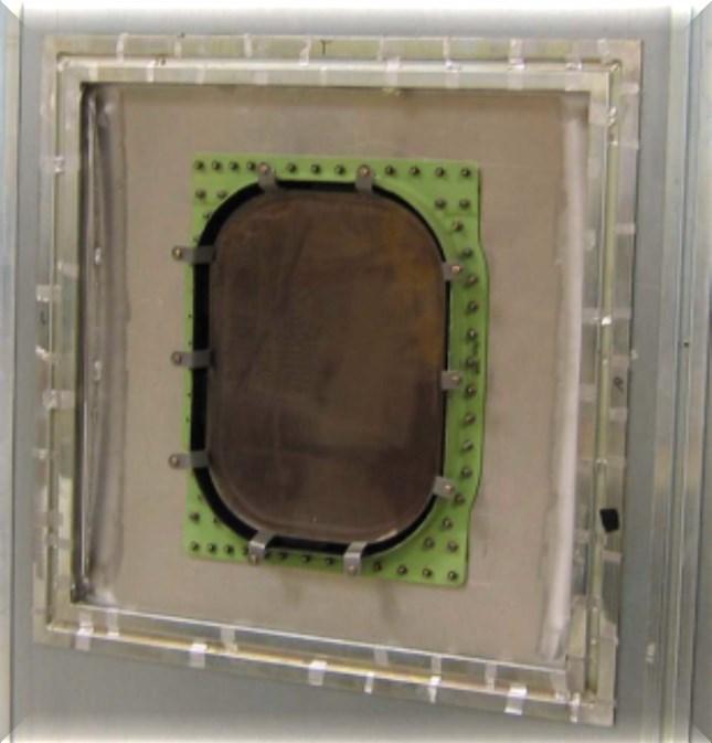
48 Measurement Applications Component Shielding 48
49 Measurement Applications Component Shielding Open-to-Short reveals useable dynamic range Sample-to-Open comparisons reveal sample shielding Data from metrology lab room showed good agreement to ideal reverb chamber setup 49
50 Agenda Reverberation Chambers Overview Discrete Frequency Stirring Metrology Application of Reverberation Chambers Probe Calibration Antenna Efficiency Measurement Applications Component Shielding Aircraft Shielding Bulk Absorption Field Mapping Wireless propagation measurements 50
51 Measurement Applications Aircraft Shielding 3 distinct types of measurements were made during the aircraft test (all utilizing the DFS measurement technique) Reverberant (Reverb) Shielding Measurements Direct Illumination Shielding Measurements Reverberant (Reverb) Attenuation Measurements 51


52 Measurement Applications Aircraft Shielding High Intensity Radiated Fields (HIRF) Certification Testing: Greater than 200 meters of cables 52


53 Measurement Applications Aircraft Shielding High power shielding measurement system 53

54 Measurement Applications Aircraft Shielding Fiber optic port extenders allowed us to go from This to this! and still improve on Dynamic range Measurement accuracy/uncertainty 54


55 Measurement Applications Aircraft Shielding 55

56 Measurement Applications Aircraft Shielding Reverb shielding measurements utilize a nested chamber approach paint hanger used as outer chamber, aircraft fuselage considered to be the inner chamber Shielding number produced is an average over all incident angles and polarizations 56
57 Measurement Applications Aircraft Shielding Reverb shielding number determined by comparing empty hanger attenuation (or insertion loss) to the aircraft inserted attenuation (Tx antenna outside the aircraft, Rx antenna inside the aircraft). Hanger insertion loss requires measurement system to have a large dynamic range. A A SE ref aircraft aircraft P P R, ref T, ref P P R, aircraft T, aircraft 10 log A A ref aircraft 57
, Flight Deck, EE Bay, Forward Cargo Bay, and Aft Cargo")
58 Measurement Applications Aircraft Shielding Measurement points 2 Tx, 3 Rx points per aircraft area Aircraft pressure hull divided into 5 aircraft areas: Main Deck (passenger cabin), Flight Deck, EE Bay, Forward Cargo Bay, and Aft Cargo Bay 58
59 Measurement Applications Aircraft Shielding Hanger Insertion Loss for empty hanger (REF1) and for hanger with aircraft (REF2) 59
60 Measurement Applications Aircraft Shielding Hanger Insertion Loss for empty hanger (REF1) and for hanger with aircraft (REF2) 60
 and for hanger with aircraft")
61 Measurement Applications Aircraft Shielding Hanger Insertion Loss for empty hanger (REF1) and for hanger with aircraft (REF2) 61
62 Measurement Applications Aircraft Shielding Directly illuminate device under test with transmit antenna; can be used to directly illuminate apertures of concern Can be used to determine a worst case shielding number 62
63 Measurement Applications Aircraft Shielding Measurement of antenna-to-antenna gain / attenuation when both transmit and receive antennas are located inside the device under test Provides an indirect assessment of cavity Q and can reveal changes to internal cavity electrical characteristics 63
64 Agenda Reverberation Chambers Overview Discrete Frequency Stirring Metrology Application of Reverberation Chambers Probe Calibration Antenna Efficiency Measurement Applications Component Shielding Aircraft Shielding Bulk Absorption Field Mapping Wireless propagation measurements 64
65 Measurement Applications Bulk Absorption Using Reverb Chamber measurement technique (DFS technique) to quantify RF absorption characteristics of complex objects Engineering problem: Ideally analyze wireless IFE with airplane full of passengers and luggage Not feasible for long-term detailed testing Looking for alternative to represent loading of the aircraft by passengers SYNTHETIC PERSONNEL USING DIELECTRIC SUBSTITUTION 65
66 Measurement Applications Bulk Absorption Dielectric Constants at 2450 MHz ε r for human head is about 39; higher for other tissues (IEEE ) Dielectric Properties of Vegetables and Fruits as a Function of Temperature, Ash, and Moisture Content, O. SIPAHIOGLU AND S.A. BARRINGER, JOURNAL OF FOOD SCIENCE Vol. 68, Nr. 1,


, Reds (low")
67 Measurement Applications Bulk Absorption Comparing Potatoes to People Starch content is a key parameter for RF Absorption Tested 2 types of potatoes: Russets (high starch), Reds (low starch) 67
68 Measurement Applications db Bulk Absorption Freq Freq. (GHz) Low Band Baseline Note: Based on correlation calculations between frequency points, we were likely over-sampling the chamber below 150 MHz All ~400 lbs of red & wht potatoes & lb. persons db Potatoes vs. People 100 to 1000 MHz Low Band Foam Chair 150 lb Person in Chair lbs of wht Freq. (GHz) 68
69 Measurement Applications Bulk Absorption -15 Potatoes vs. People db Baseline wht lb red 1 to 6 GHz -35 All 400 lb. red & wht & lb Persons Freq Freq. (GHz) db Foam Chair 150 lb personon chair lbs of wht Freq Freq (GHz)

70 Measurement Applications Bulk Absorption 70
71 Agenda Reverberation Chambers Overview Discrete Frequency Stirring Metrology Application of Reverberation Chambers Probe Calibration Antenna Efficiency Measurement Applications Bulk Absorption Component Shielding Aircraft Shielding Field Mapping Wireless propagation measurements 72

72 Measurement Applications Cavity Field Mapping Measurement of antenna-to-antenna coupling when both transmit and receive antennas are located inside the test article (aircraft, in our case) Provides an indirect assessment of cavity Q and can reveal changes to internal cavity electrical characteristics Similar measurements can be used to provide wireless channel characterization 73

73 Measurement Applications Cavity Field Mapping Results from cavity field mapping Rx 74
74 Measurement Applications Cavity Field Mapping More results from inside a large passenger cabin 75
75 Agenda Reverberation Chambers Overview Discrete Frequency Stirring Metrology Application of Reverberation Chambers Probe Calibration Antenna Efficiency Measurement Applications Bulk Absorption Component Shielding Aircraft Shielding Field Mapping Wireless propagation measurements 76
76 Measurement Applications Wireless propagation measurements Deliver DVD quality streamed unicast video to every seat Airplane is high multipath environment, but with curved boundary surfaces, how correlated will multipath be? Need Coverage, Delay Spread, Angle of Arrival / Departure statistics to build a good Airplane MIMO channel model Optimize installation locations Optimize antennas types, orientations, spacing Optimize radio designs A 2C 3A G 2D 3G K 2H 3K Conceptual coverage layout,


77 Measurement Applications Wireless propagation measurements Channel Sounding Translation Stages 78

78 Measurement Applications Wireless propagation measurements Energy across X-Z grid Energy vs. Polar Direction Energy/Angle vs. Time 79
79 Measurement Applications Wireless propagation measurements 80


80 1 2 Measurement Applications Wireless propagation measurements Angle of Arrival over Time (Seq017) Angle (deg) Time (sec) x 10-7 TX 2 Example Angle Spectrum DC-10 Seat 51E PNA , TX 1 PNA 81
81 Summary Reverberation chambers can be used to calibrate field probes with comparable uncertainties to Anechoic chambers Frequency, Spatial and Mode averaging reduce Field uniformity to level sufficient to measure antenna efficiency. Probe calibrations in reverberation chamber appear to be more repeatable than anechoic chamber method. Discreet Frequency Stirring reduces test times and is well suited for stirring aircraft Nested chambers approach is useful for characterizing odd shaped objects Statistical methods used in the lab can be utilized for evaluation of EM environment onboard aircraft 82

82 Discussion 83
REVERBERATION CHAMBER FOR EMI TESTING
 1 REVERBERATION CHAMBER FOR EMI TESTING INTRODUCTION EMI Testing 1. Whether a product is intended for military, industrial, commercial or residential use, while it must perform its intended function in
Rationale for RC Testing. Vignesh Rajamani, PhD. Research Engineer Oklahoma State University
 Rationale for RC Testing Vignesh Rajamani, PhD. Research Engineer Oklahoma State University Overview What is a reverberation chamber? Immunity testing Emissions testing Shielding effectiveness measurements
CHRISTIAN S. LÖTBÄCK PATANÉ. Master of Science Thesis
 Reverberation Chamber Performance and Methods for Estimating the Rician K-factor Evaluation of Reverberation Chamber Measurements at the National Institute of Standards and Technology in Boulder, Colorado,
pel.com Microwave & RF, March 23 rd, 2016.
 www.siep pel.com Generating high EM fields using mode-stirred reverberation chambers for RTCA DO 160 applications Jean-François ROSNARHO Microwave & RF, March 23 rd, 2016. TABLE OF CONTENTS 1. RTCA DO
Reverberation Chambers
 Reverberation Chambers Andy Lambourne 29 th November 2007 Contents 01 Introduction 02 Uses of a Reverberation Chamber 03 Example Facilities 04 Chamber Properties 05 Standards and Test Methods 06 Calibration
The NASA High Intensity Radiated Fields Laboratory. Reuben A. Williams. NASA Langley Research Center M/S 130 Hampton, Virginia
 The NASA High Intensity Radiated Fields Laboratory Reuben A. Williams NASA Langley Research Center M/S 130 Hampton, Virginia 23681-0001 ABSTRACT High Intensity Radiated Fields (HIRF) are the result of
Reverberation Chambers Design and Construction Considerations for Aerospace and Military Test Requirements
 Reverberation Chambers Design and Construction Considerations for Aerospace and Military Test Requirements REVERBERATION CHAMBERS: DESIGN AND CONSTRUCTION CONSIDERATIONS FOR AEROSPACE AND MILITARY TEST
E-Field Uniformity Test Volume In Gtem Cell Based On Labview
 www.ijecs.in International Journal Of Engineering And Computer Science ISSN:2319-7242 Volume 4 Issue 4 April 215, Page No. 11646-1165 E-Field Uniformity Test Volume In Gtem Cell Based On Labview Dominic
STSM: On-Site Emission Measurements
 On-Site Emission Measurements Based on Reverberation Chamber Techniques Robert Vogt, STSM - SP, Boras, Sweden 20.09 03.10.2015 CONTENTS On-site emission measurements (Motivation) Test site classification
Correlation Between Measured and Simulated Parameters of a Proposed Transfer Standard
 Correlation Between Measured and Simulated Parameters of a Proposed Transfer Standard Jim Nadolny AMP Incorporated ABSTRACT Total radiated power of a device can be measured using a mode stirred chamber
Numerical Study of Stirring Effects in a Mode-Stirred Reverberation Chamber by using the Finite Difference Time Domain Simulation
 Forum for Electromagnetic Research Methods and Application Technologies (FERMAT) Numerical Study of Stirring Effects in a Mode-Stirred Reverberation Chamber by using the Finite Difference Time Domain Simulation
Mode-Stirred Method Implementation for HIRF Susceptibility Testing and Results Comparison with Anechoic Method
 NASA/TM-2001-211033 Mode-Stirred Method Implementation for HIRF Susceptibility Testing and Results Comparison with Anechoic Method Truong X. Nguyen and Jay J. Ely Langley Research Center, Hampton, Virginia
Practical Considerations for Radiated Immunities Measurement using ETS-Lindgren EMC Probes
 Practical Considerations for Radiated Immunities Measurement using ETS-Lindgren EMC Probes Detectors/Modulated Field ETS-Lindgren EMC probes (HI-6022/6122, HI-6005/6105, and HI-6053/6153) use diode detectors
Immunity Test System RIS 3000 / RIS 6000 acc. to IEC/EN
 Description The setup of a radiated immunity test system can be done in the conventional way with many separate instruments or in a more comfortable and less risky way with our new EMC control unit, type
Test and Measurement for EMC
 Test and Measurement for EMC Bogdan Adamczyk, Ph.D., in.c.e. Professor of Engineering Director of the Electromagnetic Compatibility Center Grand Valley State University, Michigan, USA Ottawa, Canada July
Localization and Identifying EMC interference Sources of a Microwave Transmission Module
 Localization and Identifying EMC interference Sources of a Microwave Transmission Module Ph. Descamps 1, G. Ngamani-Njomkoue 2, D. Pasquet 1, C. Tolant 2, D. Lesénéchal 1 and P. Eudeline 2 1 LaMIPS, Laboratoire
Large E Field Generators in Semi-anechoic Chambers for Full Vehicle Immunity Testing
 Large E Field Generators in Semi-anechoic Chambers for Full Vehicle Immunity Testing Vince Rodriguez ETS-Lindgren, Inc. Abstract Several standards recommend the use of transmission line systems (TLS) as
Electromagnetic Compatibility. Wi-Fi Installations. Federal Aviation Administration. Administration. David B. Walen
 Electromagnetic Compatibility Concerns for Aircraft Wi-Fi Installations FAA/AEA WiFi Summit David B. Walen Aviation Safety Chief Scientific and Technical Advisor Electromagnetic Interference Wi-Fi EMC
Random Walk Technique: Measuring EME in Below-Deck Complex Cavities
 NAVAL SURFACE WARFARE CENTER DAHLGREN DIVISION Random Walk Technique: Measuring EME in Below-Deck Complex Cavities Presented by: Mike Slocum & Greg Tait E 3 Assessment & Evaluation Branch (Q52) 22 August
A GTEM BEST PRACTICE GUIDE APPLYING IEC TO THE USE OF GTEM CELLS
 - 27-39 H1 A BEST PRACTICE GUIDE APPLYING IEC 61-4-2 TO THE USE OF CELLS A. Nothofer, M.J. Alexander, National Physical Laboratory, Teddington, UK, D. Bozec, D. Welsh, L. Dawson, L. McCormack, A.C. Marvin,
Double-Ridged Waveguide Horn
 Model 3106 200 MHz 2 GHz Uniform Gain Power Handling up to 1.6 kw Model 3115 1 GHz 18 GHz Low VSWR Model 3116 18 GHz 40 GHz Quality Construction M O D E L 3 1 0 6 Double-Ridged Waveguide Horn PROVIDING
Future In Radiated Immunity Testing
 Future In Radiated Immunity Testing Flynn Lawrence Flynn Lawrence is an Applications Engineer for AR RF/Microwave Instrumentation. At AR, Flynn is actively engaged in new application and product development
Shielding Effectiveness Report HQDP
 HQDP Mates with QSH-DP, QTH-DP Description: 0.50mm 100Ω Differential 30 AWG Twinax Cable Assembly Samtec, Inc. 2005 All Rights Reserved Table of Contents Product Overview... 1 Test Overview... 1 Shielded
CHARACTERISATION OF IN -HOUSE EMC TESTING FACILITIES FOR PRODUCT DESIGNERS. Paul Kay* and Andrew Nafalski**
 CHARACTERISATION OF IN -HOUSE EMC TESTING FACILITIES FOR PRODUCT DESIGNERS Paul Kay* and Andrew Nafalski** *Austest Laboratories, Adelaide **University of South Australia School of Electrical and Information
Electromagnetic Compatibility ( EMC )
") Electromagnetic Compatibility ( EMC ) Introduction EMC Testing 1-2 -1 Agenda System Radiated Interference Test System Conducted Interference Test 1-2 -2 System Radiated Interference Test Open-Area Test
Electromagnetic Compatibility ( EMC ) Introduction EMC Testing 1-2 -1 Agenda System Radiated Interference Test System Conducted Interference Test 1-2 -2 System Radiated Interference Test Open-Area Test
An Introduction to Free-Field Measurements of Wireless Devices in Reverberation Chambers. Kate A. Remley, Group Leader Metrology for Wireless Systems
 An Introduction to Free-Field Measurements of Wireless Devices in Reverberation Chambers Kate A. Remley, Group Leader Metrology for Wireless Systems power (dbm) BER What is a Reverberation Chamber? A shielded,
Physically and Electrically Large Antennas for Antenna Pattern Measurements and Radar Cross Section Measurements in the Upper VHF and UHF bands
 Physically and Electrically Large Antennas for Antenna Pattern Measurements and Radar Cross Section Measurements in the Upper VHF and UHF bands Vince Rodriguez, PhD Product Manager, Antennas ETS-Lindgren,
Test Methods and Standards for RF Based Emergency Equipment
 Test Methods and Standards for RF Based Emergency Equipment Precision Indoor Personnel Location and Tracking for Emergency Responders International Technology Workshop August 1-, 011 Kate Remley, William
RADIO TEST REPORT. For MODEL NO FCC ID: C3K1703 IC ID: 3048A Test Report No. R-TR190-FCCIC-UNII-1 Issue Date: 14 September 2015
 RADIO TEST REPORT For MODEL NO. 1703 FCC ID: C3K1703 IC ID: 3048A-1703 Test Report No. R-TR190-FCCIC-UNII-1 Issue Date: 14 September 2015 FCC CFR47 Part 15 Subpart E Industry Canada RSS-247 Issue 1 Prepared
Shielding Effectiveness Report HQCD
 HQCD Mates with QSH, QTH, QSH-EM Description: 0.50mm Q Strip High Speed Coax Cable Assembly Samtec, Inc. 2005 All Rights Reserved Table of Contents Product Overview... 1 Test Overview... 1 Shielded Room
Chalmers Publication Library
 Chalmers Publication Library About Random LOS in Rician Fading Channels for MIMO OTA Tests This document has been downloaded from Chalmers Publication Library (CPL). It is the author s version of a work
FCC ID: A3LSLS-BD106Q. Report No.: HCT-RF-1801-FC003. Plot Data for Output Port 2_QPSK 9 khz ~ 150 khz Middle channel 150 khz ~ 30 MHz Low channel
 Plot Data for Output Port 2_QPSK 9 khz ~ 150 khz Middle channel 150 khz ~ 30 MHz Low channel 30 MHz ~ 1 GHz Middle channel 1 GHz ~ 2.491 GHz Low channel 2.695 GHz ~ 12.75 GHz High channel 12.75 GHz ~ 26.5
EMC ANECHOIC CHAMBERS 5-METER CHAMBERS
 ETS-Lindgren's FACT 5 Chambers offer semi-anechoic radiated emissions (RE) and fully anechoic radiated immunity (RI) compliance test capability for most international EMC compliance regulations. FACT 5
A Novel Method for Determining the Lower Bound of Antenna Efficiency
 A Novel Method for Determining the Lower Bound of Antenna Efficiency Jason B. Coder #1, John M. Ladbury 2, Mark Golkowski #3 # Department of Electrical Engineering, University of Colorado Denver 1201 5th
TEST REPORT. Covering the DYNAMIC FREQUENCY SELECTION (DFS) REQUIREMENTS OF. FCC Part 15 Subpart E (UNII) Xirrus Model(s): XN4
 REQUIREMENTS OF. FCC Part 15 Subpart E (UNII) Xirrus Model(s): XN4") TEST REPORT Covering the DYNAMIC FREQUENCY SELECTION (DFS) REQUIREMENTS OF FCC Part 15 Subpart E (UNII) Xirrus Model(s): XN4 COMPANY: TEST SITE: Xirrus 370 North Westlake Blvd., Suite 200 Westlake Village,
TEST REPORT Covering the DYNAMIC FREQUENCY SELECTION (DFS) REQUIREMENTS OF FCC Part 15 Subpart E (UNII) Xirrus Model(s): XN4 COMPANY: TEST SITE: Xirrus 370 North Westlake Blvd., Suite 200 Westlake Village,
EXHIBIT 10 TEST REPORT. FCC Parts 2 & 24
 EXHIBIT 10 TEST REPORT FCC Parts 2 & 24 SUB-EXHIBIT 10.1 MEASUREMENT PER SECTION 2.1033 (C) (14) OF THE RULES SECTION 2.1033 (c) (14) The data required by Section 2.1046 through 2.1057, inclusive, measured
Experimental Results Obtained in the Vibrating Intrinsic Reverberation Chamber
 Hollandse Signaalapparaten B.V. Research, Development & Technology Environmental Test Laboratory P.O. Box 42, 755 GD Hengelo The Netherlands leferink@signaal.nl Experimental Results Obtained in the Vibrating
Selecting the right antenna for the
 Zhong Chen ETS-Lindgren EMC Antenna Fundamentals Selecting the right antenna for the job can be a difficult task. In many cases, manufacturer terminologies and specifications are so varied that it is difficult
TRANSMITTER MODEL: KAS-2030M
 Page 1 of 16 FCC PART 15, SUBPART B and C TEST REPORT for TRANSMITTER MODEL: KAS-2030M Prepared for WILDLIFE TECHNOLOGIES 115 WOLCOTT STREET MANCHESTER, NEW HAMPSHIRE 03103 Prepared by: KYLE FUJIMOTO Approved
Version TEST REPORT NO. DATE DESCRIPTION. HCTR1208FR50 August 29, 2012 First Approval Report
 Version TEST REPORT NO. DATE DESCRIPTION First Approval Report Page 2 of 101 Table of Contents 1. GENERAL INFORMATION... 4 2. INTRODUCTION... 5 2.1. EUT DESCRIPTION... 5 2.2. MEASURING INSTRUMENT CALIBRATION...
SHIELDING EFFECTIVENESS MEASUREMENTS ON ENCLOSURES WITH VARIOUS APERTURES BY BOTH MODE-TUNED REVERBERATION CHAMBER AND GTEM CELL METHODOLOGIES
 Progress In Electromagnetics Research B, Vol. 2, 103 114, 2008 SHIELDING EFFECTIVENESS MEASUREMENTS ON ENCLOSURES WITH VARIOUS APERTURES BY BOTH MODE-TUNED REVERBERATION CHAMBER AND GTEM CELL METHODOLOGIES
AMPLIFIER RESEARCH... APPLICATION NOTE: 23
 AMPLIFIER RESEARCH... APPLICATION NOTE: 23 PRODUCTS THAT PROVIDE 200 V/m CW OR PM AT A DISTANCE OF 1 METER 1 The Amplifier / Antenna / Cell combinations shown in Table 1 provide various means of generating
Title: Test on 5.8 GHz Band Outdoor WiFi (802.11b/g) Wireless Base Station
 Wireless Base Station") Page 20 of 51 Pages 7.5. Conducted spurious emission 7.5.1. Requirements: Clause 15.247(d). In any 100 khz bandwidth outside the frequency band in which the spread spectrum or digitally modulated intentional
Page 20 of 51 Pages 7.5. Conducted spurious emission 7.5.1. Requirements: Clause 15.247(d). In any 100 khz bandwidth outside the frequency band in which the spread spectrum or digitally modulated intentional
Electromagnetic Effects, original release, dated 31 October Contents: 17 page document plus 13 Figures. Enclosure (1)
") Electromagnetic Effects, original release, dated 31 October 2005 Contents: 17 page document plus 13 Figures Enclosure (1) Electromagnetic effects. 1. Purpose. To ensure that the addition of fiber optic
Electromagnetic Effects, original release, dated 31 October 2005 Contents: 17 page document plus 13 Figures Enclosure (1) Electromagnetic effects. 1. Purpose. To ensure that the addition of fiber optic
Shielding Effectiveness Report
 VRDPC-050-01-S-D-RA Mates with VPDP/VPLSP/VPSTP Description: Data Rate I/O Cable Assemblies Samtec, Inc. 2005 All Rights Reserved Table of Contents Product Overview... 1 Shielded Room Noise Floor Verification...
Normalized Site Attenuation Test Report
 NVLAP LAB CODE 200974-0 Normalized Site Attenuation Test Report Test Specification NORMALIZED SITE ATTENUATION (NSA) Range 30 MHz 1GHz using the methods of ANSI C63.4-2009; EN 50147-2 (1997); CISPR 16-1-4
Version TEST REPORT NO. DATE DESCRIPTION. HCTR1208FR49 August 29, 2012 First Approval Report
 Version TEST REPORT NO. DATE DESCRIPTION HCTR1208FR49 August 29, 2012 First Approval Report Revise information for frequency range on page 8 Page 2 of 39 Table of Contents 1. GENERAL INFORMATION... 4 2.
TDS-535 Tuned Dipole Set Operation Manual
 TDS-535 Tuned Dipole Set Operation Manual 1 TABLE OF CONTENTS INTRODUCTION Antenna Set Contents...3 Intended Purposes...4 Range of Environmental Conditions...5 GENERAL INSTRUCTIONS General Description...5
L.S. Compliance, Inc. W66 N220 Commerce Court Cedarburg, WI
 L.S. Compliance, Inc. W66 N220 Commerce Court Cedarburg, WI 53012 262-375-4400 COMPLIANCE TESTING OF: Quartex Synchronization Transmitter Model FM-72 PREPARED FOR: Quartex, Division of Primex, Inc. 965
Double-Ridged Waveguide Horn
 Features: Maintains Single Lobe Radiation Pattern Over Frequency Ultra Broadband: 1 GHz - 18 GHz 300 W Power Input Capacity Optimized High Frequency Gain Low VSWR ETS-Lindgren s PATENT PENDING The Waveguide
SPHERICAL NEAR-FIELD MEASUREMENTS AT UHF FREQUENCIES WITH COMPLETE UNCERTAINTY ANALYSIS
 SPHERICAL NEAR-FIELD MEASUREMENTS AT UHF FREQUENCIES WITH COMPLETE UNCERTAINTY ANALYSIS Allen Newell, Patrick Pelland Nearfield Systems Inc. 19730 Magellan Drive, Torrance, CA 90502-1104 Brian Park, Ted
Ultra High Frequency Measurements
 Ultra High Frequency Measurements Desmond Fraser desmond@rheintech.com 703.689.0368 360 Herndon Parkway Suite 1400 Herndon, VA 20170 IEEE EMC DC / N. VA Chapter 31 January 2012 Overview We ll review Millimeter
Ave output power ANT 1(dBm) Ave output power ANT 2 (dbm)
 Ave output power ANT 2 (dbm)") Page 41 of 103 9.6. Test Result The test was performed with 802.11b Channel Frequency (MHz) power ANT 1(dBm) power ANT 2 (dbm) power ANT 1(mW) power ANT 2 (mw) Limits dbm / W Low 2412 7.20 7.37 5.248 5.458
Page 41 of 103 9.6. Test Result The test was performed with 802.11b Channel Frequency (MHz) power ANT 1(dBm) power ANT 2 (dbm) power ANT 1(mW) power ANT 2 (mw) Limits dbm / W Low 2412 7.20 7.37 5.248 5.458
Laird Attn: Bill Steinike W66 N220 Commerce Ct. Cedarburg, WI Report Constructed by: Zach Wilson, EMC Technician Signature: Date: June 21, 2017
 A Test Report # 317241 Equipment Under Test: RM024 Test Date(s): June 9 and June 21, 2017 Prepared for: Laird Attn: Bill Steinike W66 N220 Commerce Ct. Cedarburg, WI 53012 Report Issued by: Adam Alger,
William F. Young. This work was sponsored by the Public Safety Communications Research Lab of NIST, under Dereck Orr, Program Manager.
 William F. Young Kate A. Remley, Christopher L. Holloway, Galen Koepke, Dennis Camell, John Ladbury Electromagnetics Division National Institute of Standards and Technology (NIST) U.S. Department of Commerce,
Calibration and Validation for Automotive EMC
 Calibration and Validation for Automotive EMC Wolfgang Müllner Patrick Preiner Alexander Kriz Seibersdorf Labor GmbH 2444 Seibersdorf, Austria http://rf.seibersdorf-laboratories.at rf@seibersdorf-laboratories.at
SCOPE OF ACCREDITATION TO ISO/IEC 17025:2005 & ANSI/NCSL Z
 SCOPE OF ACCREDITATION TO ISO/IEC 17025:2005 & ANSI/NCSL Z540-1-1994 ETS-LINDGREN INC. 1301 Arrow Point Drive Cedar Park, TX 78613 Ron Bethel Phone: 512 531 6400 CALIBRATION Valid To: December 31, 2018
ETS Lindgren Anechoic Chamber
 ETS Lindgren Anechoic Chamber Provides an electromagnetically quiet environment for measuring the radiating properties of a device-undertest Enclosed by an external metallic shielding to provide isolation
Alternative Radiated Emission Test Methods Progress Achieved in IND60 Project
 Alternative Radiated Emission Test Methods Progress Achieved in IND60 Project Project EMRP IND60: Improved EMC test methods in industrial environments Mohammed Salhi 05-09 September 2016 Wroclaw, Poland
Application Note. StarMIMO. RX Diversity and MIMO OTA Test Range
 Application Note StarMIMO RX Diversity and MIMO OTA Test Range Contents Introduction P. 03 StarMIMO setup P. 04 1/ Multi-probe technology P. 05 Cluster vs Multiple Cluster setups Volume vs Number of probes
EIA STANDARD TP-66A. EMI Shielding Effectiveness Test Procedure for Electrical Connectors EIA A EIA A
 EIA STANDARD ANSI/-2000(R2007) Approved: May 5, 2000 Reaffirmed: March 1, 2007 TP-66A EMI Shielding Effectiveness Test Procedure for Electrical Connectors (Revision of EIA-364-66) MAY 2000 ELECTRONIC COMPONENTS,
E MC Ane c hoi c Chambers
 E MC Ane c hoi c Chambers.)+6! Features 6 MHz - 8 GHz Frequency Range Full Compliance Testing for Radiated Emissions: - ANSI C6. Parts 5 & 8 - EN 57 - CISPR / EN55 - CISPR 6/ EN556 - CISPR / EN55 - VCCI
Channel Modeling ETI 085
 Channel Modeling ETI 085 Overview Lecture no: 9 What is Ultra-Wideband (UWB)? Why do we need UWB channel models? UWB Channel Modeling UWB channel modeling Standardized UWB channel models Fredrik Tufvesson
MICROWAVE MICROWAVE TRAINING BENCH COMPONENT SPECIFICATIONS:
 Microwave section consists of Basic Microwave Training Bench, Advance Microwave Training Bench and Microwave Communication Training System. Microwave Training System is used to study all the concepts of
INTERNATIONAL STANDARD
 INTERNATIONAL STANDARD IEC 60489-1 1983 AMENDMENT 2 1999-05 Amendment 2 Methods of measurement for radio equipment used in the mobile services Part 1: General definitions and standard conditions of measurement
TEST REPORT... 1 CONTENT...
 CONTENT TEST REPORT... 1 CONTENT... 2 1 TEST RESULTS SUMMARY... 3 2 EMC RESULTS CONCLUSION... 4 3 LABORATORY MEASUREMENTS... 6 4 EMI TEST... 7 4.1 CONTINUOUS CONDUCTED DISTURBANCE VOLTAGE TEST... 7 4.2
Methods for Evaluating the Shielding Effectiveness of Textiles
 Tadeusz W. Więckowski Jarosław M. Janukiewicz Wrocław University of Technology, Wybrzeże Wyspiańskiego 27, 50-370 Wrocław, Poland E-mail: sekretariat@ita.pwr.wroc.pl Methods for Evaluating the Shielding
ISO INTERNATIONAL STANDARD
 INTERNATIONAL STANDARD ISO 11452-11 First edition 2010-09-01 Road vehicles Component test methods for electrical disturbances from narrowband radiated electromagnetic energy Part 11: Reverberation chamber
ACCREDITED LABORATORY. LIBERTY LABS, INC. Kimballton, IA for technical competence in the field of Calibration
 THE AMERICAN ASSOCIATION FOR LABORATORY ACCREDITATION ACCREDITED LABORATORY A2LA has accredited LIBERTY LABS, INC. Kimballton, IA for technical competence in the field of Calibration The accreditation
MIL-STD 461F Results for M&A Technology Companion epad Computer
 11 July 11 MIL-STD 461F Results for M&A Technology Companion epad Computer Prepared For: Mike Lehner M&A Technology Chenault Dr Carrolton, TX 6 Prepared By: John C. Zentner Test Engineer Integrated Demonstrations
Considerations about Radiated Emission Tests in Anechoic Chambers that do not fulfil the NSA Requirements
 6 th IMEKO TC Symposium Sept. -, 8, Florence, Italy Considerations about Radiated Emission Tests in Anechoic Chambers that do not fulfil the NSA Requirements M. Borsero, A. Dalla Chiara 3, C. Pravato,
INDUCTIVE TRI-BAND DOUBLE ELEMENT FSS FOR SPACE APPLICATIONS
 Progress In Electromagnetics Research C, Vol. 18, 87 101, 2011 INDUCTIVE TRI-BAND DOUBLE ELEMENT FSS FOR SPACE APPLICATIONS D. Ramaccia and A. Toscano Department of Applied Electronics University of Rome
NIST Activities in Wireless Coexistence
 NIST Activities in Wireless Coexistence Communications Technology Laboratory National Institute of Standards and Technology Bill Young 1, Jason Coder 2, Dan Kuester, and Yao Ma 1 william.young@nist.gov,
On The Design of Door-Less Access Passages to Shielded Enclosures
 On The Design of Door-Less Access Passages to Shielded Enclosures Vince Rodriguez NSI-MI Technologies Suwanee, GA, USA vrodriguez@nsi-mi.com Abstract RF shielded enclosures have been common features in
UWB Channel Modeling
 Channel Modeling ETIN10 Lecture no: 9 UWB Channel Modeling Fredrik Tufvesson & Johan Kåredal, Department of Electrical and Information Technology fredrik.tufvesson@eit.lth.se 2011-02-21 Fredrik Tufvesson
OUTDOOR SOUND MODULE/TRANSMITTER MODEL: THE BANDIT
 Page 1 of 16 FCC PART 15, SUBPART B and C TEST REPORT for OUTDOOR SOUND MODULE/TRANSMITTER MODEL: THE BANDIT Prepared for MINASKA OUTDOORS 6517 PLATTE AVENUE LINCOLN, NEBRASKA 68507 Prepared by: KYLE FUJIMOTO
FISCHER CUSTOM COMMUNICATIONS, INC.
 FISCHER CUSTOM COMMUNICATIONS, INC. Current Probe Catalog FISCHER CUSTOM COMMUNICATIONS, INC. Fischer Custom Communications, Inc., is a manufacturer of custom electric and magnetic field sensors for military
Pico 900MHz 1W FHSS Module Model: p900 FCC ID: NS913P900. Applicant:
 Pico 900MHz 1W FHSS Module Model: p900 Applicant: Microhard Systems Inc. 150 Country Hills Landing NW Calgary, Alberta Canada T3K 5P3 In Accordance With Federal Communications Commission (FCC) Part 15,
Test Plan for Hearing Aid Compatibility
 Test Plan for Hearing Aid Compatibility Version Number 3.1 February 2017 2017 CTIA - The Wireless Association. All rights reserved. CTIA hereby grants to CTIA Authorized Testing Laboratories (CATLs), and
MEASUREMENT TRAINING SUMMIT
 MEASUREMENT TRAINING SUMMIT AND World Metrology Day Celebration! Tuesday, May 20 and Wednesday, May 21, 2014 $75 1 Day / $150 2 Day Bring your oldest metrology artifact! Join us for this two-day Measurement
A Method for Gain over Temperature Measurements Using Two Hot Noise Sources
 A Method for Gain over Temperature Measurements Using Two Hot Noise Sources Vince Rodriguez and Charles Osborne MI Technologies: Suwanee, 30024 GA, USA vrodriguez@mitechnologies.com Abstract P Gain over
EFFECT OF SHIELDING ON CABLE RF INGRESS MEASUREMENTS LARRY COHEN
 EFFECT OF SHIELDING ON CABLE RF INGRESS MEASUREMENTS LARRY COHEN OVERVIEW Purpose: Examine the common-mode and differential RF ingress levels of 4-pair UTP, F/UTP, and F/FTP cables at an (RJ45) MDI port
DARE!! Instruments Application Note GHz Radiated RF Immunity Testing
 DARE!! Instruments Application Note 14.001 1 6 GHz Radiated RF Immunity Testing EM Field Generation Contents 1. Introduction... 4 2. Power or Field?... 4 3. The conventional setup... 5 4. Antenna and Amplifier
Final Report. Bilateral Comparison on Electric Field Measurements Between TÜBİTAK UME and SASO NMCC GULFMET.EM.RF-S1. UME-EM-D
 Final Report Bilateral Comparison on Electric Field Measurements Between TÜBİTAK UME and SASO NMCC GULFMET.EM.RF-S1 UME-EM-D3-2.23.6.a Çağlar ASLAN Abdullah M. ALROBAISH Osman ŞEN (Rev. 0) July 25, 2017
Model: M /800 MHz Mobile Radio
 Engineering and Testing for EMC and Safety Compliance Accredited Under NVLAP Lab Code 200061-0 RF Maximum Permissible Exposure (MPE) Report for Controlled and Uncontrolled Environments M/A-COM, Inc. 221
Absorbers and Anechoic Chamber Measurements
 Absorbers and Anechoic Chamber Measurements Zhong Chen Director, RF Engineering ETS-Lindgren 1301 Arrow Point Dr. Cedar Park, TX, 78613 Zhong.chen@ets-lindgren.com SUMMARY Absorber Overview Absorber Materials
Shielding Effectiveness Summary Results for RadiaShield Technologies, Inc. RadiaShield Fabric
 Test Date(s): July 9 through July 19, 2010 UST Project Number: 10-0164 Summary Results for Product Description The Sample Under Test (SUT) is the. The SUT is a textile which is used as a protective shield
Propagation Mechanism
 Propagation Mechanism ELE 492 FUNDAMENTALS OF WIRELESS COMMUNICATIONS 1 Propagation Mechanism Simplest propagation channel is the free space: Tx free space Rx In a more realistic scenario, there may be
UL Japan, Inc. Head Office EMC Lab Asama-cho, Ise-shi, Mie-ken JAPAN Telephone : Facsimile :
 Page : 2 of 19 CONTENTS PAGE SECTION 1: Client information... 3 SECTION 2: Equipment under test (E.U.T.)... 3 SECTION 3: Test specification, procedures & results... 5 SECTION 4: Operation of E.U.T. during
Application Note #60 Harmonic Measurement for IEC And other Radiated Immunity Standards
 Application Note #60 Harmonic Measurement for IEC 61000-4-3 And other Radiated Immunity Standards By: Applications Engineering In the rush to complete RF immunity testing on schedule, it is not all that
CHAPTER 6 EMI EMC MEASUREMENTS AND STANDARDS FOR TRACKED VEHICLES (MIL APPLICATION)
") 147 CHAPTER 6 EMI EMC MEASUREMENTS AND STANDARDS FOR TRACKED VEHICLES (MIL APPLICATION) 6.1 INTRODUCTION The electrical and electronic devices, circuits and systems are capable of emitting the electromagnetic
147 CHAPTER 6 EMI EMC MEASUREMENTS AND STANDARDS FOR TRACKED VEHICLES (MIL APPLICATION) 6.1 INTRODUCTION The electrical and electronic devices, circuits and systems are capable of emitting the electromagnetic
A LARGE COMBINATION HORIZONTAL AND VERTICAL NEAR FIELD MEASUREMENT FACILITY FOR SATELLITE ANTENNA CHARACTERIZATION
 A LARGE COMBINATION HORIZONTAL AND VERTICAL NEAR FIELD MEASUREMENT FACILITY FOR SATELLITE ANTENNA CHARACTERIZATION John Demas Nearfield Systems Inc. 1330 E. 223rd Street Bldg. 524 Carson, CA 90745 USA
Resonant Frequencies in Aviation Platforms. Robert Jarrett Branch
 Resonant Frequencies in Aviation Platforms by Robert Jarrett Branch A thesis submitted to the Graduate Faculty of Auburn University in partial fulfillment of the requirements for the Degree of Master of
Regarding RF Isolation for small Enclosures
 Regarding RF Isolation for small Enclosures IEEE electromagnetic society and IEEE standard board has published standards for measuring the shielding effectiveness (SE) of chambers. The measurement methods
FCC PART & IC RSS GHz FHSS TEST REPORT
 FCC PART 15.247 & IC RSS-247 2.4 GHz FHSS TEST REPORT 849 NW State Road 45 Newberry, FL 32669 USA Ph.: 888.472.2424 or 352.472.5500 Fax: 352.472.2030 Email: info@timcoengr.com Website: www.timcoengr.com
Diversity Performance of an Optimized Meander PIFA Array for MIMO Handsets
 Diversity Performance of an Optimized Meander PIFA Array for MIMO Handsets Qiong Wang *, Dirk Plettemeier *, Hui Zhang *, Klaus Wolf *, Eckhard Ohlmer + * Dresden University of Technology, Chair for RF
Model 3140B BiConiLog Antenna User Manual
 Model 3140B BiConiLog Antenna User Manual Model 3140B mounted onto a 7-TR tripod (not included) ETS-Lindgren L.P. reserves the right to make changes to any product described herein in order to improve
Model AS18071, M1, M2 AR System 10kHz 18GHz
 Model AS18071, M1, M2 AR System 10kHz 18GHz The AS18071 AR System is a comprehensive equipment package designed to perform turnkey Radiated Susceptibility testing using the Reverberation Chamber method.
AMPLIFIER RESEARCH... APPLICATION NOTE: 20
 AMPLIFIER RESEARCH... APPLICATION NOTE: 20 AMPLIFIER RESEARCH PRODUCTS THAT PROVIDE 20 V/m CW OR PM AT A DISTANCE OF 1 METER 1 The Amplifier / Antenna / Cell combinations shown in Table 1 provide various
FCC Test Report. : Wireless Way Richmond, BC, V6V 3A4 Canada : 47 CFR FCC Part 27 Subpart L
 FCC Test Report FCC ID Equipment Model No. Brand Name Applicant Address Standard : N7NHL7688 : Wireless Module : HL7688 : AirPrime : Sierra Wireless Inc. Received Date : Jul. 12, 2016 : 13811 Wireless