Model 3140B BiConiLog Antenna User Manual
|
|
|
- Clarence Lester
- 5 years ago
- Views:
Transcription


1 Model 3140B BiConiLog Antenna User Manual Model 3140B mounted onto a 7-TR tripod (not included)
2 ETS-Lindgren L.P. reserves the right to make changes to any product described herein in order to improve function, design, or for any other reason. Nothing contained herein shall constitute ETS-Lindgren L.P. assuming any liability whatsoever arising out of the application or use of any product or circuit described herein. ETS-Lindgren L.P. does not convey any license under its patent rights or the rights of others. Copyright by ETS-Lindgren L.P. All Rights Reserved. No part of this document may be copied by any means without written permission from ETS-Lindgren L.P. Trademarks used in this document: The ETS-Lindgren logo, MiniMast, and BiConiLog are trademarks of ETS-Lindgren L.P. Revision Record MANUAL,MODEL 3140 Part #399258, Rev. E Revision Description Date A Initial Release November, 2000 B Edits/updates January, 2002 C Edits/updates January, 2003 D Edits/updates May, 2003 E Rebrand May, 2010 ii
3 Table of Contents Notes, Cautions, and Warnings... v 1.0 Introduction... 7 About Mounting the Model 3140B TR Tripod Positioner... 9 ETS-Lindgren Product Information Bulletin Maintenance About Calibration Service Procedures Specifications Electrical Specifications Physical Specifications Assembly Instructions Model 3140B Components Model 3140B Assembled Steps to Assemble the Model 3140B Attach Bow Tie Elements Attach T Leg Elements Attach Diagonal Struts Attach V Elements Mounting Instructions Included Mounting Adapters Using Included Adapters to Mount to an Offset Boom Attach Included Mounting Adapters to Model 3140B Attach Model 3140B to an ETS-Lindgren Offset Boom Mounting Illustrations Model 3140B on 7-TR Tripod Positioner Model 3140B on Model 2075 MiniMast Model 3140B on Model 2070/2071 Antenna Positioning Mast Additional Mounting Options TR and Mast Mounting Options x2 Boom Mounting Options Application iii
4 7.0 Typical Data Model 3140B Typical VSWR Model 3140B Typical Antenna Factors Model 3140B Gain Model 3140B Typical Forward Power (FP) Typical 1 Meter FP Based on 1 Meter Antenna Factor Typical 3 Meter FP Based on 3 Meter Antenna Factor Typical 3 Meter FP Over Ferrite Tile Typical 3 Meter FP Measured Over Conducting Ground Appendix A: Warranty iv
5 Notes, Cautions, and Warnings Note: Denotes helpful information intended to provide tips for better use of the product. Caution: Denotes a hazard. Failure to follow instructions could result in minor personal injury and/or property damage. Included text gives proper procedures. Warning: Denotes a hazard. Failure to follow instructions could result in SEVERE personal injury and/or property damage. Included text gives proper procedures. See the ETS-Lindgren Product Information Bulletin for safety, regulatory, and other product marking information. v
6 This page intentionally left blank. vi


7 1.0 Introduction The ETS-Lindgren Model 3140B BiConiLog TM is a high-field antenna in the bow tie/log periodic family, providing the highest field-to-power ratio at low frequencies of any of the BiConiLog antennas. The Model 3140B is designed specifically to generate the field levels required for immunity/susceptibility tests required by standards such as IEC/EN using the lowest amount of input power possible. A BiConiLog antenna combines a broadband biconical-like bow tie antenna with a standard log periodic dipole array (LPDA) to replace the traditional use of two antennas in the 26 MHz to 3000 MHz electromagnetic compatibility (EMC) test frequency range. Many EMC antennas are variations of a standard tuned dipole, which must be nearly half a wavelength long to transmit or receive energy most efficiently; at 26 MHz, a tuned dipole would have to be approximately 5.3 meters long, 4.6 meters long at 30 MHz, and 2.8 meters long at 50 MHz. This is unwieldy for many anechoic chambers and test sites. The end plates of the Model 3140B T bow ties make the bow tie antenna segment look like an antenna twice as long as the actual 1.6 meter length. The result is about a 10 db improvement in low frequency transmit gain compared to a regular bow tie of the same length. Although bow ties have been used for all of the elements on some log periodic antenna designs in the past, in EMC applications the advantage gained is an extension of the useful low frequency range of the typical LPDA from 100 MHz down to 26 MHz. At 26 MHz, an efficient single dipole type antenna must be over five meters long, whereas suitable performance is obtained here with a 1.6 meter bow tie. A simple wire outline bow tie antenna is narrowband compared to a sheet bow tie or biconical, so struts are added to the Model 3140B bow ties to better simulate the broadband sheet bow tie. Introduction 7
8 The unique feature of the Model 3140B is the T bow tie elements. A T bow tie increases the equivalent dipole electrical length, thereby decreasing resonant frequency and increasing efficiency in the 20 MHz to 60 MHz range. Similarly, a regular bow tie has a lower resonant frequency than an equal length single-wire dipole. The T bow tie has the first resonance at a frequency where the length is about 0.22λ, a regular bow tie at a length of 0.3λ, and a tuned dipole at about 0.48λ. Thus at 50 MHz the 1.4 meter long T bow tie of the Model 3140B behaves like a 2.8 meter tuned dipole. Cross-polar radiation is minimized because current flow on one of the T end frames is almost exactly cancelled by the oppositely-phased current on the other T end. The standard self-balun feed of the log periodic also provides a matched balanced feed to the bow tie elements. To prevent cable pickup below 100 MHz and to improve matching to the bow tie elements, the Model 3140B contains a balun transformer which acts as a common-mode choke to keep unbalanced current off the coaxial feed cable outer shield, as well as adding some additional inductance to improve impedance matching to the bow ties. Even though the Model 3140B is highly balanced (symmetry +/- 0.5 db), in vertically polarized measurements cable position can effect results, so it is recommended that the cable be suspended horizontally back from the antenna at least one meter before any vertical drop. Below 150 MHz bow tie radiation dominates with a dipole-like pattern, while above 150 MHz the radiation in the plane of the elements is directional. The Model 3140B is designed only for immunity testing. The large size of the antenna makes it impractical for emissions testing where height scanning is required, and the bow tie end plates increase the measurement uncertainty when the antenna is polarized vertically. For that reason, individual calibrations are not provided for the Model 3140B. 8 Introduction
9 About Mounting the Model 3140B The Model 3140B can be mounted on the 2-in square booms of these ETS-Lindgren products: Model 7-TR Tripod Positioner Model 2075 MiniMast Model 2070/2071 Antenna Positioning Mast See Mounting Illustrations on page 26 for diagrams showing the Model 3140B mounted to these ETS-Lindgren products. For the variety of mounting options available for the Model 3140B, see Mounting Instructions on page TR TRIPOD POSITIONER ETS-Lindgren offers the non-metallic, non-reflective Model 7-TR for use at both indoor and outdoor EMC test sites. Constructed of PVC and fiberglass components, providing increased stability for physically large antennas. The unique design allows for quick assembly, disassembly, and convenient storage. Allows several different configurations, including options for manual or pneumatic polarization. Quick height adjustment and locking wheels provide ease of use during testing. Maximum height is 2.17 m (85.8 in), with a minimum height of 0.8 m (31.8 in). This tripod can support a 13.5 kg (30 lb) load. Introduction 9
10 ETS-Lindgren Product Information Bulletin See the ETS-Lindgren Product Information Bulletin included with your shipment for the following: Warranty information Safety, regulatory, and other product marking information Steps to receive your shipment Steps to return a component for service ETS-Lindgren calibration service ETS-Lindgren contact information 10 Introduction
11 2.0 Maintenance Before performing any maintenance, follow the safety information in the ETS-Lindgren Product Information Bulletin included with your shipment. WARRANTY Maintenance of the Model 3140B is limited to external components such as cables or connectors. If you have any questions concerning maintenance, contact ETS-Lindgren Customer Service. About Calibration The Model 3140B BiConiLog TM Antenna was designed for immunity testing, so the generated field is measured with a calibrated field probe, not the Model 3140B. For that reason, it is not required that the Model 3140B be recalibrated regularly. If you would like to have your Model 3140B antenna verified or serviced please contact ETS-Lindgren Calibration. See the Product Information Bulletin included with your shipment for information on ETS-Lindgren calibration services. Service Procedures For the steps to return a system or system component to ETS-Lindgren for service, see the Product Information Bulletin included with your shipment. Maintenance 11
12 This page intentionally left blank. 12 Maintenance
13 3.0 Specifications Electrical Specifications Frequency Range: Input Impedance: 26 MHz 3000 MHz 50 Ω VSWR (Average): 2:1 CW Power (Average): 26 MHz to 150 MHz = 750 W 150 MHz to 600 MHz = 500 W 600 MHz to 1 GHz = 365 W 1 GHz to 3 GHz = 200 W Symmetry: Connector: +/- 0.5 db Type N female Physical Specifications Height (T Bow Tie): Width (T Bow Tie): Depth (Length): Weight: cm (30.18 in) cm (63.60 in) cm (59.6 in) 10 kg (22 lb) Specifications 13
14 This page intentionally left blank. 14 Specifications
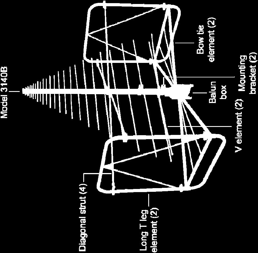
15 4.0 Assembly Instructions Before connecting any components, follow the safety information in the ETS-Lindgren Product Information Bulletin included with your shipment. Model 3140B Components The Model 3140B BiConiLog Antenna consists of the following: Antenna Bow tie elements (2) Long T leg elements (2) Diagonal struts (4) V elements (2) Boom assembly Mount knobs (2): one 7/8-in (104169) and one 1/4-in (104136) Polarizing adapters (100989) for booms with 7/8-in mount holes (2) Thread inserts (105861B) 7/8 in-to-1/4 in (2) Assembly Instructions 15

16 Model 3140B Assembled 16 Assembly Instructions


17 Steps to Assemble the Model 3140B To eliminate stress and prevent damage to the balun box connection, you must support the antenna while attaching the bow tie elements. ATTACH BOW TIE ELEMENTS 1. Place the bow tie vertically on the floor and hold the antenna horizontally. See illustration on next page. 2. Fit the bow tie into one side of the balun. 3. Insert and tighten the knob. 4. Carefully place the antenna in a vertical position with the feet of the balun box level and on a flat surface. 5. Repeat steps 2 and 3 to attach the second bow tie element to the balun box. Assembly Instructions 17
18 18 Assembly Instructions
19 ATTACH T LEG ELEMENTS 6. Insert one long T leg element into the clamp and tighten the clamp screws. See illustration on next page. 7. Repeat for second T leg element. Assembly Instructions 19
20 20 Assembly Instructions
21 ATTACH DIAGONAL STRUTS 8. Attach the four diagonal struts. Loosen the thumbscrew at each strut mount on the T leg element and at the boom. Place the pocket of the straight end facing the raised face of each mount. Tighten the thumbscrew. Assembly Instructions 21
22 ATTACH V ELEMENTS 9. Attach the V elements and tighten the thumbscrews through the boom The Model 3140B is now ready for mounting to a tripod or mast. See Mounting Instructions on page Assembly Instructions
23 5.0 Mounting Instructions Before connecting any components, follow the safety information in the ETS-Lindgren Product Information Bulletin included with your shipment. The Model 3140B is a precision measurement device. Handle with care. Do not mount the Model 3140B onto an ETS-Lindgren 4-TR Tripod. Included Mounting Adapters The Model 3140B BiConiLog ships with these mounting adapters: Polarizing Mounting Adapter with 7/8 14 thread receptacle (2) If you need to convert the polarizing adapter to a 1/4 20 receptacle, insert the 1/4 20 thread insert into the polarizing adapter B 1/4 20 Thread Insert (2) Mounting Instructions 23


24 Using Included Adapters to Mount to an Offset Boom ATTACH INCLUDED MOUNTING ADAPTERS TO MODEL 3140B To allow manual polarization of the Model 3140B, install the polarizing adapters with the curve at the top of each adapter facing the same direction. To prohibit manual polarization, install one adapter with the curve facing the opposite direction from the other. 1. Place one polarizing adapter between the shoulders of one of the mounting brackets on the antenna. Do not cross thread or permanent damage to the adapter and thread insert could occur. 2. Thread a bracket knob through the mounting bracket, then through the polarizing adapter, and finally through the hex nut. 3. Tighten the mounting knob to secure the antenna. 4. Repeat steps 1, 2, and 3 for the remaining polarizing adapter and mounting bracket. 24 Mounting Instructions
25 ATTACH MODEL 3140B TO AN ETS-LINDGREN OFFSET BOOM 1. Place the Model 3140B onto the offset boom with the attached polarizing adapters flat against the top surface of the boom. 2. Holding the Model 3140B securely, insert one B 1/4 20 thread insert into the underside of the offset boom. 3. Attach the two mount knobs and tighten to secure the Model 3140B to the offset boom. Mounting Instructions 25
26 Mounting Illustrations MODEL 3140B ON 7-TR TRIPOD POSITIONER 26 Mounting Instructions


27 MODEL 3140B ON MODEL 2075 MINIMAST Mounting Instructions 27


28 MODEL 3140B ON MODEL 2070/2071 ANTENNA POSITIONING MAST 28 Mounting Instructions

29 Additional Mounting Options 7-TR AND MAST MOUNTING OPTIONS Following are options for mounting the Model 3140B onto an ETS-Lindgren 7-TR Tripod or mast. Contact the ETS-Lindgren Sales Department for information on ordering optional mounting hardware. Mast refers to 2070 Series, 2075, and 2175 Antenna Towers. 7-TR refers to , , and booms: boom Straight boom; for general antenna mounting on a 7-TR boom Offset boom; for general antenna mounting on a 7-TR with pneumatic or manual polarization boom Center rotate boom; for rear-mount stinger-type antennas only Mounting Instructions 29

30 2X2 BOOM MOUNTING OPTIONS Following are options for mounting the Model 3140B onto a 2x2 boom. Contact the ETS-Lindgren Sales Department for information on ordering optional mounting hardware. 2x2 boom refers to a typical 2-inch by 2-inch boom 30 Mounting Instructions
31 6.0 Application After mounting the Model 3140B BiConiLog TM, connect an N-type coaxial cable from the antenna connector to a signal generator or amplifier. Contact with any metal or non-metallic structure can capacitively load the antenna, which may cause unrepeatable results. Therefore, make sure that no part of the dipole elements or bow ties is in contact with the tripod or tower, particularly in vertically-polarized tests. Where possible, run the feed cable straight back at least one meter or more from the Model 3140B before dropping vertically. Both horizontal and vertical polarizations are easily accomplished when the Model 3140B is mounted on an ETS-Lindgren tower. The Model 7-TR Tripod Positioner is designed specifically for T bow tie BiConiLog antennas for easy changes to polarization, and with the air polarization option can provide automated polarization using a Model 2090 Multi-Device Controller. See Mounting Instructions on page 23 for mounting schemes for ETS-Lindgren towers and the 7-TR Tripod. For immunity testing, the electric field strength generated at a distance d can be approximated by: Pg V/m = 30 d E( ) d = distance, in meters g = numeric gain (10 G[dB]/10 ) P = antenna net input power, in watts An estimate of the power required for any field strength E can be obtained from the forward power graphs in Typical Data on page 33, which shows forward power required in watts to generate 1 V/m. While the formula provided previously is based on the net power (forward minus reflected) transmitted by the antenna, the gain determined from the antenna factor already contains effects due to mismatch, so the formula then predicts the required forward power rather than net power. To determine the power (in watts) required for any other field strength not shown, multiply the power required for 1 V/m by the desired E-field squared, or Application 31
32 2 ( V/m) = E P( 1 V/m) PE To determine the additional amplifier overhead required to handle 80% amplitude modulation, multiply the result by 3.24 (1.8 2 ). Actual transmitted field strength should be verified using an ETS-Lindgren Model HI-6005 Field Probe, or equivalent. The forward power data graphs on page 39 and page 40 show power requirements for the lower frequencies at three meters based on measurements using a field probe on an Open Area Test Site (OATS) over both conducting ground and a (2.4m) 2 ferrite absorber field over conducting ground. For IEC type testing, the antenna tip can be placed at any distance between one and three meters from the Equipment Under Test (EUT) as long as the front face plane is illuminated according to the -0, +6 db uniform field specification. In general, closer distances require less power to create a given field strength. 32 Application
33 7.0 Typical Data Model 3140B Typical VSWR This graph illustrates the typical VSWR for Model 3140B in the frequency range 26 MHz to 3000 MHz. Typical Data 33
34 Model 3140B Typical Antenna Factors This graph illustrates the typical horizontal antenna factors for the Model 3140B in the frequency range 26 MHz to 3000 MHz. The separation distance for the ANSI C63.5 three and 10 meter calibrations is measured from the antenna midpoint, while for SAE/ARP-958 one meter calibrations the distance is measured from the antenna tip. Midpoint is defined as half the distance between the small elements and the bow ties, which is about 65 cm from the small end tip. 34 Typical Data
35 Model 3140B Gain This graph illustrates one and three meter gain. Typical Data 35
36 Model 3140B Typical Forward Power (FP) The forward power graphs illustrate the typical forward power required for one, three, and 10 V/m (with and without 80% amplitude modulation). The graph on page 37 illustrates one meter from the tip of the antenna, and the graph on page 38 illustrates three meters from the tip of the antenna. The graphs on page 39 and page 40 illustrate power requirements for the lower frequencies at three meters based on measurements using a field probe on an Open Area Test Site (OATS) over both conducting ground and a (2.4m) 2 ferrite absorber field over conducting ground. The power shown was measured with 1.5 meter transmit antenna and probe height and horizontal polarization. Horizontal polarization represents the worst-case power requirement; typically less power is required for vertical polarization. In practice, many users place ferrite tiles on the ground between the antenna and probe to reduce reflected-ray interference. For any other field strength E, multiply the power in watts for 1 V/m by E Typical Data
37 TYPICAL 1 METER FP BASED ON 1 METER ANTENNA FACTOR Typical Data 37
38 TYPICAL 3 METER FP BASED ON 3 METER ANTENNA FACTOR 38 Typical Data
39 TYPICAL 3 METER FP OVER FERRITE TILE V/m 80% AM 10 V/m 1 V/m 80% AM 3 V/m 1 V/m 80% AM 1 V/m Frequency (MHz) Forward Power (W) Typical Data 39
40 TYPICAL 3 METER FP MEASURED OVER CONDUCTING GROUND V/m 80% AM 10 V/m 1 V/m 80% AM 3 V/m 1 V/m 80% AM 1 V/m Frequency (MHz) Forward Power (W) 40 Typical Data
41 Appendix A: Warranty See the Product Information Bulletin included with your shipment for the complete ETS-Lindgren warranty for your Model 3140B. DURATION OF WARRANTIES FOR MODEL 3140B All product warranties, except the warranty of title, and all remedies for warranty failures are limited to two years. Product Warranted Model 3140B BiConiLog TM Duration of Warranty Period 2 Years Warranty 41
Model BiConiLog Antenna. User Manual
 Model 3149 BiConiLog Antenna User Manual ETS-Lindgren Inc. reserves the right to make changes to any products herein to improve functioning or design. Although the information in this document has been
Log Periodic Dipole Array Antenna
 Model 3148B Log Periodic Dipole Array Antenna User Manual ETS-Lindgren L.P. reserves the right to make changes to any product described herein in order to improve function, design, or for any other reason.
Archived 3/18/10 USER MANUAL EMCO MODEL 3141 BICONILOG TM LOG-PERIODIC / T BOW-TIE ANTENNA Rev A 01/97
 USER MANUAL EMCO MODEL 3141 BICONILOG TM LOG-PERIODIC / T BOW-TIE ANTENNA 399236 Rev A 01/97 GENERAL DESCRIPTION The EMCO Model 3141 is the latest evolution in the popular bow-tie/log periodic combination
Model 3180B Mini-Bicon Antenna User Manual
 Model 3180B Mini-Bicon Antenna User Manual Model 3180B with conical elements Model 3180B with cage elements ETS-Lindgren L.P. reserves the right to make changes to any product described herein in order
Double-Ridged Waveguide Horn Antennas
 Models 3112, 3106B, 3119, 3115, 3117, 3116C Double-Ridged Waveguide Horn Antennas User Manual ETS-Lindgren Inc. Although the information in this document has been carefully reviewed and is believed to
Model 3104C. Biconical Antenna. User Manual
 Model 3104C Biconical Antenna User Manual ETS-Lindgren L.P. reserves the right to make changes to any product described herein in order to improve function, design, or for any other reason. Nothing contained
Model Biconical Antenna. User Manual
 Model 3109 Biconical Antenna User Manual ETS-Lindgren L.P. reserves the right to make changes to any product described herein in order to improve function, design, or for any other reason. Nothing contained
Model Biconical Antenna. User Manual
 Model 3109 Biconical Antenna User Manual ETS-Lindgren Inc. reserves the right to make changes to any products herein to improve functioning or design. Although the information in this document has been
Model 3142B BiConiLog Antenna
 Model 3142B BiConiLog Antenna MANUAL EMC TEST SYSTEMS, L.P. MARCH 2002 Introduction EMC Test Systems, L.P. reserves the right to make changes to any product described herein in order to improve function,
Advanced Test Equipment Rentals ATEC (2832)
") Established 1981 Advanced Test Equipment Rentals www.atecorp.com 800-404-ATEC (2832) 6500 Series Loop Antennas User Manual ETS-Lindgren Inc. reserves the right to make changes to any product described
Established 1981 Advanced Test Equipment Rentals www.atecorp.com 800-404-ATEC (2832) 6500 Series Loop Antennas User Manual ETS-Lindgren Inc. reserves the right to make changes to any product described
Model 3148 & Log-Periodic Dipole Array Antenna
 Established 1981 Advanced Test Equipment Rentals www.atecorp.com 800-404-ATEC (2832) Model 3148 & 93148 Log-Periodic Dipole Array Antenna MANUAL EMC TEST SYSTEMS, L.P. SEPTEMBER 2002 EMC Test Systems,
Current Probes. User Manual
 Current Probes User Manual ETS-Lindgren Inc. reserves the right to make changes to any product described herein in order to improve function, design, or for any other reason. Nothing contained herein shall
Model 3725/2M. Line Impedance Stabilization Network (LISN) User Manual
 User Manual") Model 3725/2M Line Impedance Stabilization Network (LISN) User Manual ETS-Lindgren L.P. reserves the right to make changes to any product described herein in order to improve function, design, or for any
Model 3725/2M Line Impedance Stabilization Network (LISN) User Manual ETS-Lindgren L.P. reserves the right to make changes to any product described herein in order to improve function, design, or for any
Model 3101, 3102 and 3103 Conical Log-Spiral Antennas
 Model 3101, 3102 and 3103 Conical Log-Spiral Antennas MANUAL EMC TEST SYSTEMS, L.P. SEPTEMBER 2002 EMC Test Systems, L.P. reserves the right to make changes to any products herein to improve functioning,
Model 3116 Double-Ridged Waveguide Horn
 Model 3116 Double-Ridged Waveguide Horn MANUAL EMC TEST SYSTEMS, L.P. MARCH 2002 EMC Test Systems, L.P. reserves the right to make changes to any product described herein in order to improve function,
SAS Log Periodic Antenna Operation Manual
 SAS-512-2 Log Periodic Antenna Operation Manual 1 TABLE OF CONTENTS INTRODUCTION Introduction...3 Intended Purposes...4 Optional Equipment...5 OPERATING INSTRUCTIONS Assembly Instructions...6 Mounting
Advanced Test Equipment Rentals ATEC (2832)
") Established 1981 Advanced Test Equipment Rentals www.atecorp.com 800-404-ATEC (2832) A.H. Systems Model TDS-536 Tuned Dipole Set TDS-536 TV Dipole Set Operation Manual 1 TABLE OF CONTENTS WARRANTY 2 INTRODUCTION
Established 1981 Advanced Test Equipment Rentals www.atecorp.com 800-404-ATEC (2832) A.H. Systems Model TDS-536 Tuned Dipole Set TDS-536 TV Dipole Set Operation Manual 1 TABLE OF CONTENTS WARRANTY 2 INTRODUCTION
SAS-543 Biconical Antenna Operation Manual
 SAS-543 Biconical Antenna Operation Manual 1 TABLE OF CONTENTS INTRODUCTION Introduction...3 Intended Purposes...4 Optional Equipment...5 OPERATING INSTRUCTIONS Assembly Instructions...6 Mounting Instructions...6
TDS-535 Tuned Dipole Set Operation Manual
 TDS-535 Tuned Dipole Set Operation Manual 1 TABLE OF CONTENTS INTRODUCTION Antenna Set Contents...3 Intended Purposes...4 Range of Environmental Conditions...5 GENERAL INSTRUCTIONS General Description...5
MANUAL. PCD - Precision Conical Dipole Antenna
 MANUAL PCD - Precision Conical Dipole Antenna RF Engineering MANUAL Precision Conical Dipole Antenna 12.10.2009 Version 2.0 Notice Seibersdorf Labor GmbH reserves the right to make changes to any product
Model 3110B Biconical Antenna
 Established 1981 Advanced Test Equipment Rentals www.atecorp.com 800-404-ATEC (2832) Archived 3/18/10 Model 3110B Biconical Antenna MANUAL EMC TEST SYSTEMS, L.P. MARCH 2002 EMC Test Systems, L.P. reserves
Calibration Comparison System
 HI-2790B Calibration Comparison System User Manual ETS-Lindgren Inc. reserves the right to make changes to any products herein to improve functioning or design. Although the information in this document
Model 3106 Double-Ridged Waveguide Horn
 Established 1981 Advanced Test Equipment Rentals www.atecorp.com 800-404-ATEC (2832) Model 3106 Double-Ridged Waveguide Horn MANUAL EMC TEST SYSTEMS, L.P. MARCH 2002 EMC Test Systems, L.P. reserves the
COMBILOG ANTENNA MODEL AC MHz. rev: 0202
 COMBILOG ANTENNA 30-2000 MHz MODEL AC-220 rev: 0202 WARRANTY All equipment manufactured by Com-Power Corporation is warranted against defects in material and workmanship for a period of two (2) years from
Bulk Current Injection Probe Test Procedure
 Bulk Current Injection Probe Test Procedure 1 TABLE OF CONTENTS INTRODUCTION 3 GENERAL INFORMATION 4 TEST METHODS 6 SAFETY 8 FIGURES 9 FORMULAS 12 MAINTENANCE 13 WARRANTY 14 2 INTRODUCTION CURRENT PROBE
Double-Ridged Waveguide Horn
 Model 3106 200 MHz 2 GHz Uniform Gain Power Handling up to 1.6 kw Model 3115 1 GHz 18 GHz Low VSWR Model 3116 18 GHz 40 GHz Quality Construction M O D E L 3 1 0 6 Double-Ridged Waveguide Horn PROVIDING
Active Monopole Antenna
 Model 3301C Active Monopole Antenna User Manual Model 3301C Antenna Base ETS-Lindgren L.P. reserves the right to make changes to any product described herein in order to improve function, design, or for
AK-18G Antenna Kit Operation Manual
 AK-18G Antenna Kit Operation Manual 1 TABLE OF CONTENTS WARRANTY 3 INTRODUCTION 4 GENERAL INFORMATION 5 OPTIONAL EQUIPMENT 8 FORMULAS 9 MAINTENANCE 10 2 WARRANTY INFORMATION A.H. Systems Inc., warrants
Current Probe Fixture Instruction Manual
 Current Probe Fixture Instruction Manual 1 TABLE OF CONTENTS INTRODUCTION 3 GENERAL INFORMATION 4 TEST METHODS 5 SAFETY 7 FIGURES 8 FORMULAS 10 MAINTENANCE 11 WARRANTY 12 2 INTRODUCTION figure 1 Mechanical
Electromagnetic Compatibility ( EMC )
") Electromagnetic Compatibility ( EMC ) Introduction EMC Testing 1-2 -1 Agenda System Radiated Interference Test System Conducted Interference Test 1-2 -2 System Radiated Interference Test Open-Area Test
Electromagnetic Compatibility ( EMC ) Introduction EMC Testing 1-2 -1 Agenda System Radiated Interference Test System Conducted Interference Test 1-2 -2 System Radiated Interference Test Open-Area Test
Dinesh Micro Waves & Electronics
 Product Overview The Precision Biconical Antenna is a new generation biconical dipole with linear polarizations that covers the operating frequency range of 20 MHz to 300 MHz and its moderate power handling
Advanced Test Equipment Rentals ATEC (2832)
") Established 1981 Advanced Test Equipment Rentals www.atecorp.com 800-404-ATEC (2832) A.H. Systems Model Active Monopole Antennas Active Monopole Antenna Series Operation Manual 1 TABLE OF CONTENTS INTRODUCTION
Established 1981 Advanced Test Equipment Rentals www.atecorp.com 800-404-ATEC (2832) A.H. Systems Model Active Monopole Antennas Active Monopole Antenna Series Operation Manual 1 TABLE OF CONTENTS INTRODUCTION
INSTRUCTION MANUAL. Specifications Mechanical. 1 5/8 to 2 1/16 O.D. (41mm to 52mm)
") 308 Industrial Park Road Starkville, MS 39759 USA Ph: (662) 323-9538 FAX: (662) 323- General Description Model VB-25FM 2-Meter 5 Elements Beam INSTRUCTION MANUAL This antenna is a 5-element, 2-meter beam
308 Industrial Park Road Starkville, MS 39759 USA Ph: (662) 323-9538 FAX: (662) 323- General Description Model VB-25FM 2-Meter 5 Elements Beam INSTRUCTION MANUAL This antenna is a 5-element, 2-meter beam
TZ-RD-1740 Rotary Dipole Instruction Manual
 TZ-RD-1740 17/40m Rotary Dipole Instruction Manual The TZ-RD-1740 is a loaded dipole antenna for the 40m band and a full size rotary dipole for the 17m band. The antenna uses an aluminium radiating section
INSTRUCTION MANUAL TRI-PLATE LINE MODEL EM-7310
 INSTRUCTION MANUAL TRI-PLATE LINE MODEL EM-7310 INSTRUCTION MANUAL THIS INSTRUCTION MANUAL AND ITS ASSOCIATED INFORMATION IS PRO- PRIETARY. UNAUTHORIZED REPRO- DUCTION IS FORBIDDEN. 1998 ELECTRO-METRICS
E MC Ane c hoi c Chambers
 E MC Ane c hoi c Chambers.)+6! Features 6 MHz - 8 GHz Frequency Range Full Compliance Testing for Radiated Emissions: - ANSI C6. Parts 5 & 8 - EN 57 - CISPR / EN55 - CISPR 6/ EN556 - CISPR / EN55 - VCCI
Double-Ridged Waveguide Horn
 Features: Maintains Single Lobe Radiation Pattern Over Frequency Ultra Broadband: 1 GHz - 18 GHz 300 W Power Input Capacity Optimized High Frequency Gain Low VSWR ETS-Lindgren s PATENT PENDING The Waveguide
LOG PERIODIC ANTENNA MODEL LPA MHz - 1 GHz
 INSTRUCTION MANUAL LOG PERIODIC ANTENNA 200 MHz - 1 GHz INSTRUCTION MANUAL THIS INSTRUCTION MANUAL AND ITS ASSOCIATED INFORMATION IS PROPRIETARY. UNAUTHORIZED REPRODUCTION IS FORBIDDEN. 1993 ELECTRO-METRICS
PARABOLIC ANTENNA MODEL MTA GHz 10.0 GHz
 INSTRUCTION MANUAL PARABOLIC ANTENNA MODEL MTA-60 1.0 GHz 10.0 GHz INSTRUCTION MANUAL THIS INSTRUCTION MANUAL AND ITS ASSOCIATED INFORMATION IS PROPRIETARY. UNAUTHORIZED REPRODUCTION IS FORBIDDEN. 1993
Log Periodic Antenna
 Page 1 of 10 Log Periodic Antenna ALFM 80120 88 MHz to 108 MHz (Extendible to 80 to 120 MHz) Page 2 of 10 Table of Contents 1.0 Introduction... 3 2.0 Product Specifications... 4 3.0 Important Safety Precautions...
Characteristics of Biconical Antennas Used for EMC Measurements
 Advance Topics in Electromagnetic Compatibility Characteristics of Biconical Antennas Used for EMC Measurements Mohsen Koohestani koohestani.mohsen@epfl.ch Outline State-of-the-art of EMC Antennas Biconical
INSTRUCTION MANUAL. Specifications Electrical. Front-To-Back Ratio VSWR at Resonance Less than 1.5:1 Nominal Impedance. Mechanical
 300 Industrial Park Road, Starkville, MS 39759 Ph: (662) 323-8538 FAX: (662) 323-6551 TH-3JRS Tri-band HF 3 Elements Beam Covers 10, 15 and 20 Meters INSTRUCTION MANUAL WARNING Installation of this product
A short, off-center fed dipole for 40 m and 20 m by Daniel Marks, KW4TI
 A short, off-center fed dipole for 40 m and 20 m by Daniel Marks, KW4TI Version 2017-Nov-7 Abstract: This antenna is a 20 to 25 foot long (6.0 m to 7.6 m) off-center fed dipole antenna for the 20 m and
AK-285R Shielding Effectiveness Antenna Kit Operation Manual
 AK-285R Shielding Effectiveness Antenna Kit Operation Manual 1 TABLE OF CONTENTS WARRANTY 3 INTRODUCTION 4 GENERAL INFORMATION 5 EQUIPMENT 6 DYNAMIC RANGE 11 ANTENNA FORMULAS 13 CONVERSION FORMULAS 14
MOUNTING INSTRUCTIONS
 Standard Mounting Bracket Tilting Bracket* Mounting example Right side for upper tilt from 0 to 20 20 Spare parts: p/n SA197 Materials: extruded aluminum Hardware: stainless & zinc plated steel Dimensions
Selecting the right antenna for the
 Zhong Chen ETS-Lindgren EMC Antenna Fundamentals Selecting the right antenna for the job can be a difficult task. In many cases, manufacturer terminologies and specifications are so varied that it is difficult
M2 Antenna Systems, Inc. Model No: 2M HO LOOP
 M2 Antenna Systems, Inc. Model No: 2M HO LOOP SPECIFICATIONS: Model... 2M HO LOOP Frequency Range... 144 To 144.5 MHz Gain, Typical @ 10 ft.... 4 dbd @ 10 deg. Gain, 2 STK @ 82 & 132... 8 dbd @ 9 deg.
Electrical Field Distribution*
 Features l 30 MHz to MHz frequency range l Wide beamwidth illuminates a large uniform area l High power balun handles up to 10 kw RF input power l Tilt-angle, height and polarization are easily adjustable
EMC ANECHOIC CHAMBERS 5-METER CHAMBERS
 ETS-Lindgren's FACT 5 Chambers offer semi-anechoic radiated emissions (RE) and fully anechoic radiated immunity (RI) compliance test capability for most international EMC compliance regulations. FACT 5
SAS-551 Passive Monopole Antenna Operation Manual
 SAS-551 Passive Monopole Antenna Operation Manual 1 TABLE OF CONTENTS INTRODUCTION 3 SPECIFICATIONS 5 OPERATING INSTRUCTIONS 6 ANTENNA FORMULAS 8 CALIBRATION 10 MAINTENANCE 11 WARRANTY 12 2 INTRODUCTION
Broadband Current Probe Series Operation Manual
 Broadband Current Probe Series Operation Manual 1 TABLE OF CONTENTS WARRANTY 3 INTRODUCTION 4 GENERAL INFORMATION 5 OPERATING INSTRUCTIONS 6 FORMULAS 7 MAINTENANCE 8 2 WARRANTY INFORMATION A.H. Systems
LJ element beam for 10 or 12 meters INSTRUCTION MANUAL. CAUTION: Read All Instructions Before Operating Equipment
 LJ-113 3 element beam for 10 or 1 meters INSTRUCTION MANUAL CAUTION: Read All Instructions Before Operating Equipment 308 Industrial Park Road Starkville, MS 39759 USA Tel: 66-33-9538 Fax: 66-33-6551 VERSION
SAS-563B Active Loop Antenna Operation Manual
 SAS-563B Active Loop Antenna Operation Manual 1 TABLE OF CONTENTS INTRODUCTION 3 SPECIFICATIONS 5 OPERATING INSTRUCTIONS 7 CALCULATIONS 11 ANTENNA FORMULAS 12 MAINTENANCE 13 WARRANTY 14 2 INTRODUCTION
Accredited Standards Committee C63 - EMC
 Draft C63.-5-201x Annex N Site-Specific Qualification Procedure for Hybrid Antennas (intended to be used for the making of ANSI C63.4-201x Final Compliance Measurements) Harry H. Hodes, NCE Principal EMC
87.5 TO MHz BAND II 2 WAY 4.8dBi STACKED DIPOLE ANTENNA
 87.5 TO 108.0 MHz BAND II 2 WAY 4.8dBi STACKED DIPOLE ANTENNA 1. INTRODUCTION 3 1.1. GENERAL INFORMATION 3 1.2. UNPACKING AND CHECKING 3 1.3. WARRANTY 3 1.4. USER SAFETY RESPONSIBILITY 4 1.5. INSTALLATION
Yagi and Omni Antennas Installation Manual
 Yagi and Omni Antennas Installation Manual 25500445 Rev. A0 0218 Printed in U.S.A. Copyright 2018 Federal Signal Corporation Limited Warranty This product is subject to and covered by a limited warranty,
Double-Ridged Waveguide Horn
 Established 1981 Advanced Test Equipment Rentals www.atecorp.com 800-404-ATEC (2832) EMC Antennas 3-D Patterns Available at /3117 FEATURES: Ultra Broadband: 1 GHz - 18 GHz Maintains Single Lobe Radiation
Semi Anechoic Chamber (SAC)
") 1 of 9 Semi Anechoic Chamber (SAC) Approximate Dimensions of 3m Semi Anechoic Chamber (SAC) Length: 10m Width: 9m Height: 9m Frequency range of Semi Anechoic Chamber: 9 KHz to 40 GHz Emission test (EMI):
1 of 9 Semi Anechoic Chamber (SAC) Approximate Dimensions of 3m Semi Anechoic Chamber (SAC) Length: 10m Width: 9m Height: 9m Frequency range of Semi Anechoic Chamber: 9 KHz to 40 GHz Emission test (EMI):
We ve Bent The Rules. AR s Bent-Element Approach Provides A Size Reduction Of Up To 75%, Along With Great Performance.
 Antennas 76 We ve Bent The Rules. AR s Bent-Element Approach Provides A Size Reduction Of Up To 75%, Along With Great Performance. AR is doing incredible things with antennas. For starters, we ve advanced
L.S. Compliance, Inc. W66 N220 Commerce Court Cedarburg, WI
 L.S. Compliance, Inc. W66 N220 Commerce Court Cedarburg, WI 53012 262-375-4400 COMPLIANCE TESTING OF: Quartex Synchronization Transmitter Model FM-72 PREPARED FOR: Quartex, Division of Primex, Inc. 965
Model VB-23FM 2-Meter 3-Element Beam
 308 Industrial Park Road Starkville, MS 39759 USA Ph: (662) 323-9538 FAX: (662) Model VB-23FM 2-Meter 3-Element Beam [ INSTRUCTION MANUAL Figure 1 Overall View and Boom Detail GENERAL DESCRIPTION This
Transmission lines. Characteristics Applications Connectors
 Transmission lines Characteristics Applications Connectors Transmission Lines Connect They allow us to conduct RF Signals between our station components, they connect: Transceivers Antennas Tuners Amplifiers
Paradigm. Connect100 Installation Guide
 Paradigm GX Connect100 Installation Guide Paradigm GX Safe Use WARNING Radiation Hazard. Transmitter power levels are sufficient to cause blindness or other serious injury to body tissue. Do not power
DARE!! Instruments Application Note GHz Radiated RF Immunity Testing
 DARE!! Instruments Application Note 14.001 1 6 GHz Radiated RF Immunity Testing EM Field Generation Contents 1. Introduction... 4 2. Power or Field?... 4 3. The conventional setup... 5 4. Antenna and Amplifier
RF Emissions Test Report To Determine Compliance With: FCC, Part 15 Rules and Regulations
 RF Emissions Test Report To Determine Compliance With: FCC, Part 15 Rules and Regulations Model numbers: HT130022 Rev. B. December 17, 2002 Manufacturer: HQ, Inc. 210 9th Steet Drive Palmetto, FL 34221
M2 Antenna Systems, Inc. Model No: 2M7
 M2 Antenna Systems, Inc. Model No: 2M7 SPECIFICATIONS: Model... 2M7 Frequency Range... 144 To 148 MHz *Gain... 12.3 dbi Front to back... 20 db Typical Beamwidth... E=43 H=50 Feed type... T Match Feed Impedance....
HP ProCurve 6.9/7.7dBi Dual Band Directional Antenna (J8999A) Guide
 Guide") HP ProCurve 6.9/7.7dBi Dual Band Directional Antenna (J8999A) Guide SAFETY The HP ProCurve J8999A and all associated equipment should be installed in accordance with applicable local and national electrical
HP ProCurve 6.9/7.7dBi Dual Band Directional Antenna (J8999A) Guide SAFETY The HP ProCurve J8999A and all associated equipment should be installed in accordance with applicable local and national electrical
MFJ-219/219N 440 MHz UHF SWR Analyzer TABLE OF CONTENTS
 MFJ-219/219N 440 MHz UHF SWR Analyzer TABLE OF CONTENTS Introduction...2 Powering The MFJ-219/219N...3 Battery Installation...3 Operation Of The MFJ-219/219N...4 SWR and the MFJ-219/219N...4 Measuring
GTEM For emission and immunity testing according to IEC/EN Introduction
 page 1 of 9 GTEM-1750 For emission and immunity testing according to IEC/EN 61000-4-20 Introduction The GTEMCELL GTEM-1750 is a TEM waveguide with the upper frequency limit extended to the GHz range. It
Cisco Aironet Dual-Band MIMO Wall-Mounted Omnidirectional Antenna (AIR-ANT2544V4M-R)
") Cisco Aironet Dual-Band MIMO Wall-Mounted Omnidirectional Antenna (AIR-ANT2544V4M-R) This document outlines the specifications for the Cisco Aironet 2.4-GHz/5-GHz Dual-Band MIMO Wall-Mounted Omnidirectional
Cisco Aironet Dual-Band MIMO Wall-Mounted Omnidirectional Antenna (AIR-ANT2544V4M-R) This document outlines the specifications for the Cisco Aironet 2.4-GHz/5-GHz Dual-Band MIMO Wall-Mounted Omnidirectional
M2 Antenna Systems, Inc. Model No: 2M5WL
 M2 Antenna Systems, Inc. Model No: 2M5WL SPECIFICATIONS: Model... 2M5WL Frequency Range... 144 To 148 MHz *Gain... 16.84 dbi Front to back... 22 db Typical Beamwidth... E=26 H=29 Feed type... T Match Feed
INSTRUCTION MANUAL V-42R. Dual Band Collinear Gain Vertical for MHz and GENERAL DESCRIPTION
 308 Industrial Park Road, Starkville, MS 39759 USA Ph: (662) 323-9538 FAX: (662) 323-6551 V-42R Dual Band Collinear Gain Vertical for 144-148 MHz and 436-450 INSTRUCTION MANUAL GENERAL DESCRIPTION The
Radio Frequency Lighting Devices (RFLDs)
") Issue 2 February 2007 Spectrum Management and Telecommunications Interference-Causing Equipment Standard Radio Frequency Lighting Devices (RFLDs) Aussi disponible en français NMB-005 Contents 1. General...
Issue 2 February 2007 Spectrum Management and Telecommunications Interference-Causing Equipment Standard Radio Frequency Lighting Devices (RFLDs) Aussi disponible en français NMB-005 Contents 1. General...
Range Considerations for RF Networks
 TI Technology Days 2010 Range Considerations for RF Networks Richard Wallace Abstract The antenna can be one of the most daunting components of wireless designs. Most information available relates to large
SAS-562B Active Loop Antenna Operation Manual
 SAS-562B Active Loop Antenna Operation Manual 1 TABLE OF CONTENTS INTRODUCTION 3 SPECIFICATIONS 5 OPERATING INSTRUCTIONS 7 CALCULATIONS 11 ANTENNA FORMULAS 12 MAINTENANCE 13 WARRANTY 14 2 INTRODUCTION
MFJ-2100 INSTRUCTION MANUAL. CAUTION: Read All Instructions Before Operating Equipment
 MFJ-2100 INSTRUCTION MANUAL CAUTION: Read All Instructions Before Operating Equipment 300 Industrial Park Road Starkville, MS 39759 USA Tel: 662-323-5869 Fax: 662-323-6551 COPYRIGHT C 2015 MFJ Enterprises
NSA Calculation of Anechoic Chamber Using Method of Moment
 200 Progress In Electromagnetics Research Symposium 2006, Cambridge, USA, March 26-29 NSA Calculation of Anechoic Chamber Using Method of Moment T. Sasaki, Y. Watanabe, and M. Tokuda Musashi Institute
7. Transmitter Radiated Spurious Emissions and Conducted Spurious Emission
 7. Transmitter Radiated Spurious Emissions and Conducted Spurious Emission 7.1 Test Setup Refer to the APPENDIX I. 7.2 Limit According to 15.247(d), in any 100 khz bandwidth outside the frequency band
JK-65 Five Element 6M Yagi
 JK-65 Five Element 6M Yagi PO Box 266, Croton Falls, NY 10519-0266 845.228.8700 (TEL) 845.279.5526 (FAX) info@jkantennas.com Page 1 of 8 JK Antennas Limited Warranty and Liability JK Antennas ( Manufacturer
M2 Antenna Systems, Inc. Model No: 20M5LD
 M2 Antenna Systems, Inc. Model No: 20M5LD SPECIFICATIONS: Model... 20M5LD Frequency Range... 14.0 14.350 MHz *Gain (Full Band)... 10.2 dbi Typical Front to back... 23 db Typical Beamwidth... E=50 / H=66
LOOP ANTENNA MODEL ALR-30M. 9 khz 30 MHz
 INSTRUCTION MANUAL LOOP ANTENNA MODEL ALR-30M 9 khz 30 MHz INSTRUCTION MANUAL THIS INSTRUCTION MANUAL AND ITS ASSOCIATED INFORMATION IS PROPRIETARY. UNAUTHORIZED REPRODUCTION IS FORBIDDEN. 1995 ELECTRO-METRICS
PARALLEL ELEMENT ANTENNA MODEL PEA-30
 INSTRUCTION MANUAL PARALLEL ELEMENT ANTENNA MODEL PEA-30 10 khz 30 MHz INSTRUCTION MANUAL THIS INSTRUCTION MANUAL AND ITS ASSOCIATED INFORMATION IS PROPRIETARY. UNAUTHORIZED REPRODUCTION IS FORBIDDEN.
Antenna Product Guide
 2 0 0 6 TABLE OF CONTENTS Introduction..........................................................3 standardhorns....................................................... 4 biconicals............................................................6
Broadband Current Probe Series Operation Manual
 Broadband Current Probe Series Operation Manual 1 TABLE OF CONTENTS INTRODUCTION 3 GENERAL INFORMATION 4 OPERATING INSTRUCTIONS 5 FORMULAS 6 MAINTENANCE 7 WARRANTY 8 2 INTRODUCTION CURRENT PROBE SPECIFICATIONS
Feed Line Currents for Neophytes.
 Feed Line Currents for Neophytes. This paper discusses the sources of feed line currents and the methods used to control them. During the course of this paper two sources of feed line currents are discussed:
INSTRUCTION MANUAL For LINE IMPEDANCE STABILIZATION NETWORK. Model LI khz to 10 MHz
 Page 1 of 10 INSTRUCTION MANUAL For LINE IMPEDANCE STABILIZATION NETWORK Model LI-4100 10 khz to 10 MHz Page 2 of 10 Table of Contents 1.0 Introduction... 3 2.0 Product Description... 4 3.0 Product Specifications...
Physically and Electrically Large Antennas for Antenna Pattern Measurements and Radar Cross Section Measurements in the Upper VHF and UHF bands
 Physically and Electrically Large Antennas for Antenna Pattern Measurements and Radar Cross Section Measurements in the Upper VHF and UHF bands Vince Rodriguez, PhD Product Manager, Antennas ETS-Lindgren,
Introduction LOADING COIL COUNTERPOISE ATTACHMENT ANTENNA ATTACHMENT. Figure 1: MFJ-1625 Window/Balcony Mount Antenna
 Introduction MFJ-1625 The MFJ-1625 is a 200 Watt antenna tuner that was designed to provide portable or permanent HF communications on 80 through 10 meters and VHF on 6 meters. The universal mount design
Cisco Aironet Six-Element Dual-Band MIMO Patch Array Antenna (AIR-ANT25137NP-R)
") Cisco Aironet Six-Element Dual-Band MIMO Patch Array Antenna (AIR-ANT25137NP-R) August 2, 2013 This document describes the AIR-ANT25137NP-R antenna and provides instructions for mounting it. The antenna
Cisco Aironet Six-Element Dual-Band MIMO Patch Array Antenna (AIR-ANT25137NP-R) August 2, 2013 This document describes the AIR-ANT25137NP-R antenna and provides instructions for mounting it. The antenna
Normalized Site Attenuation Test Report
 NVLAP LAB CODE 200974-0 Normalized Site Attenuation Test Report Test Specification NORMALIZED SITE ATTENUATION (NSA) Range 30 MHz 1GHz using the methods of ANSI C63.4-2009; EN 50147-2 (1997); CISPR 16-1-4
ALWAYS ATTACH THE SAFETY ROPE TO A STABLE SUPPORT BEFORE ATTEMPTING TO ATTACH THE UNIVERSAL MOUNT TO A WINDOW FRAME OR RAIL.
 MFJ-1623 Introduction The MFJ-1623 was designed to provide portable or permanent HF communications on 30 through 10 meters and VHF on 6 meters. The universal mount design allows the user to install the
Model Near-Field Probe Set. User Manual
 Model 7405 Near-Field Probe Set User Manual ETS-Lindgren L.P. reserves the right to make changes to any product described herein in order to improve function, design, or for any other reason. Nothing contained
INTERNATIONAL STANDARD
 INTERNATIONAL STANDARD IEC 60489-1 1983 AMENDMENT 2 1999-05 Amendment 2 Methods of measurement for radio equipment used in the mobile services Part 1: General definitions and standard conditions of measurement
User Guide. Keysight N6850A Broadband Omnidirectional Antenna
 User Guide Keysight N6850A Broadband Omnidirectional Antenna Notices Keysight Technologies, Inc. 2012-2015 No part of this manual may be reproduced in any form or by any means (including electronic storage
MODEL 3810/2 Line Impedance Stabilization Network
 EMC TEST SYSTEMS FEBRUARY 1996 REV C PN 399197 MODEL 3810/2 Line Impedance Stabilization Network OPERATION MANUAL USA P.O. Box 80589 Austin, Texas 78708-0589 2205 Kramer Lane, Austin, Texas 78758-4047
REVERBERATION CHAMBER FOR EMI TESTING
 1 REVERBERATION CHAMBER FOR EMI TESTING INTRODUCTION EMI Testing 1. Whether a product is intended for military, industrial, commercial or residential use, while it must perform its intended function in
M2 Antenna Systems, Inc. Model No: 2M4
 M2 Antenna Systems, Inc. Model No: 2M4 SPECIFICATIONS: Model... 2M4 Frequency Range... 144 To 148 MHz *Gain... 9.6 dbi Front to back... 20 db Typical Beamwidth... E=54 H=74 Feed type... T Match Feed Impedance....
Correlation Between Measured and Simulated Parameters of a Proposed Transfer Standard
 Correlation Between Measured and Simulated Parameters of a Proposed Transfer Standard Jim Nadolny AMP Incorporated ABSTRACT Total radiated power of a device can be measured using a mode stirred chamber
Cisco Aironet 2.4-GHz/5-GHz 8-dBi Directional Antenna (AIR-ANT2588P3M-N)
") Cisco Aironet.4-GHz/5-GHz 8-dBi Directional Antenna (AIR-ANT588P3M-N) This document outlines the specifications for the Cisco Aironet AIR-ANT588P3M-N.4/5-GHz 8-dBi 3-Port Directional Antenna with N-connectors
Cisco Aironet.4-GHz/5-GHz 8-dBi Directional Antenna (AIR-ANT588P3M-N) This document outlines the specifications for the Cisco Aironet AIR-ANT588P3M-N.4/5-GHz 8-dBi 3-Port Directional Antenna with N-connectors
Immunity Test System RIS 3000 / RIS 6000 acc. to IEC/EN
 Description The setup of a radiated immunity test system can be done in the conventional way with many separate instruments or in a more comfortable and less risky way with our new EMC control unit, type