Electromagnetic Effects, original release, dated 31 October Contents: 17 page document plus 13 Figures. Enclosure (1)
|
|
|
- Virgil Garrett
- 6 years ago
- Views:
Transcription
1
2
3 Electromagnetic Effects, original release, dated 31 October 2005 Contents: 17 page document plus 13 Figures Enclosure (1)
4 Electromagnetic effects. 1. Purpose. To ensure that the addition of fiber optic components (such as cables or connectors) and related fittings (connectorized or feedthrough) maintain the shielding effectiveness of the pre-existing structure or enclosure at a value that is greater than the minimum specified value. 2. Applicable documents IEEE MIL-PRF MIL-PRF Requirement. a. Cable (M85045, ). The propagated radio frequency (RF) attenuation of the modified enclosure, inclusive of the fiber optic cable and related fittings shall be not less than 100 db attenuation for frequencies not greater than 1 GHz and 60 db attenuation at 10 GHz. b. Connectors (M28876, ). The propagated radio frequency (RF) attenuation of the modified enclosure, inclusive of the fiber optic connector and related fittings shall be not less than 60 db attenuation for frequencies not greater than 10 GHz. 4. Frequency a. Required frequencies. The minimum number of test frequencies to be used is shown in Table 1. b. Frequency bands. The basic frequency bands for evaluation are from 9 khz to 18 GHz. c. Below required test frequencies. Below 20 MHz both H & E fields shall be evaluated. Testing across this frequency band may be swept, or measured at discrete frequencies in sufficient number to ensure accurate results, as described in the approved Test Procedure. TABLE I. Electromagnetic effects test frequencies. Test frequency Field propagation Planewave 100 MHz 400 MHz 1 GHz Microwave 10 GHz of 17
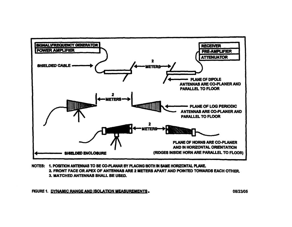
5 5. Test Methodology. a. Intent. The test methodology employed in evaluating the effects of the fiber optic modification to the enclosure consists of distinct measurement phases. This test is performed to determine the propagation characteristics (either towards attenuation or towards conduction) of the cable through a waveguide or of a connector. In general, look at the test results for a relative increase in the signal strength. This increase relates to a decrease in the shielding effectiveness of the component under test. b. Dynamic range (Instrumentation): This step is intended to illustrate the instrumentation to be employed in the evaluation is working properly and has significant dynamic range (as defined in IEEE-STD-299) to adequately measure the full range of frequency and sensitivity relative to the noise floor to discriminate low levels signals and to establish the baseline signal relationship between the transmit and receiving systems without any attenuation present. This step will also define the repeatable transmit equipment settings to be used in follow on stages of the evaluation. c. Isolation measurement of enclosure shielding (Enclosure): This step will establish the baseline shielding effectiveness of the existing (unmodified) enclosure using the settings and procedures used in the previous step. Measurements made are to include those in the vicinity of utility entrances, doors and access panels. d. Isolation measurement of enclosure shielding with fitting installed (Enclosure with fitting): This step will determine the resultant shielding effectiveness of the enclosure with the penetrative fitting (feedthrough or connectorized). Measurements made are to include those in the vicinity of the access panel where the waveguide for testing of cable or receptacle for testing of a connector will later be installed. e. Resultant Shielding Effectiveness of the DUT (Enclosure with DUT installed in fitting): This step will determine the resultant shielding effectiveness of the enclosure with the complete fiber optic cable or connector installation, inclusive of any fittings or hardware. f. Analysis: A comparison of shielding effectiveness levels for pre-existing and modified enclosure configurations, and determination of acceptability of any degradation in shielding effectiveness observed. 6. Test Equipment. a. Transmitting equipment. The drive system is to include the following: signal/frequency source (generator), power amplifier (if required), optional preamplifier, transmit antenna, shielded cable. See Table II for antenna types. Matched antennas must be used (transmit & receive). See addendum A. b. Receiving equipment. The sensing system is to include the following: receiver (such as a spectrum analyzer), optional pre-amplifier, attenuator, receive antenna, shielded cable. See Table II for antenna types. c. Equipment verifications. 2 of 17
6 (1) Matched antennas. Provide documentation to verify matched antennas are used and for which frequency(s), generating and receiving equipment have sufficient capacity and sensitivity, respectively. (2) Calibration. Provide NIST traceable calibration information. See addendum B. (3) Interconnecting cabling. Verify that connecting cables have 50 Ohm impedance (to obtain maximum power transfer). (4) Authorization to radiate. See addendum C. d. Shielded enclosure. The minimum value for the shielding effectiveness of the shielded enclosure at each frequency shall be no less than the requirement for the propagated radio frequency at each frequency tested. e. Other. Dielectric tripods, dielectric tie-offs. f. Connector test specimen configuration. The connector plug shall be terminated with at least 5 meters of multiple fiber cable. The connector receptacle shall be terminated with at least 2 meters of OFCC (termini with single fiber cables to fill each cavity in the connector receptacle). Unless otherwise specified in the approved Test Procedure, MIL-PRF cable shall be used. TABLE II. Antenna types. Field propagation Planewave Microwave Antenna type Log periodic or dipole Horn 7. Test Procedure. a. Dynamic range (Instrumentation). (1) Intent. Verify that the test equipment has the functionality to perform the measurements by determining if there is sufficient dynamic range (transmit and receive gain). Measure the amplitude of the transmitted signal via the receive system without an attentuative structure in place. (2) Setup. (a) Location. Verification should be performed in a low RF ambient environment, preferably anechoic. This may occur inside the shielded enclosure, provided the signal source equipment ambient does not affect the measurement. Care should be taken to electrically isolate the power sources for transmitting and receiving equipment. (b) Positioning. Each matched pair of antennas used for the test is placed in the horizontal plane (see figure 1). The transmit and receive antennas should be placed two meters apart and at least two meters from any reflective surface. Note: The 2 meter distance between the transmit antenna and the receive antenna is required (as shown in figure 1). The only exception to maintaining this 2 meter distance is if the positioning of the receive antenna within 5 cm from the access panel (for the subsequent isolation 3 of 17
7 and shielding effectiveness measurements) is blocked by a permanent, non-removable obstruction (which may include anechoic or other radiation absorbing/insulating materials). If this blockage is the case, a request for an allowance must be submitted to the Qualifying Activity. The additional distance, if allowed, is the one that permits the receive antenna to be the closest achievable without making contact with the obstruction. If the allowance is approved, then the distance between antennas are to be increased by the additional distance for the dynamic range measurement also. The dynamic range of the equipment must be above the signal level specified for the applicable component in 7.a(3)(b) at this increased distance. Note: The 2 meter distance requirement, relative to the floor as a reflecting surface, is dependent upon the type of antenna used. Log periodic and horn antennas are directional (beam like that of a flashlight) and are not of concern since the radiation pattern will not illuminate the floor. The dipole antenna is multi directional with a radiation pattern that will reflect off the floor when in the horizontal position. This is of concern since an error up to 6 db can occur. A dipole antenna must be positioned at least 2 meters from a reflective floor for this test. (c) Measures to maximize coupling. In general, three measures taken to obtain maximum energy out of the receive antenna (maximum coupling) are no polarization mismatch, co-planar orientation and distancing for peak of the beam. For this document, antenna positioning shall ensure a co-planar orientation and no polarization mismatch (see 7a(3)(c) below). Antennas distancing is not required to be in the peak of the beam; however, the same angular alignment (shipboard "yaw" equivalent) must be maintained between the front faces of the transmit antenna and the receive antenna for all side view measurements. An attenuator may be used to reduce the radiated signal strength and avoid amplifier saturation. Radiated signal strength attenuation by deviation from the specified distance between antennas (of two meters) is not permitted. (3) Procedure. (a) Ambient verification measurement (transmitter-off measurement): With the transmit system off, verify the local ambient levels are adequate. For each frequency identified in the approved Test Procedure, tune the receiver to the specified test frequency using the designated antenna for that frequency. Maximize radiated signal strength as stated in 7a(3)(c) below. Record the measure ambient level for each frequency. Repeat for each required frequency. Note: This measurement is designated as P 1 if a power level is measured, or E 1 if a voltage level is measured. All measurements are made at the receive antenna. (b) Measurement of signal level induced in receive antenna (transmitter-on measurement): For each frequency used above, tune the transmitter and receiver to each specified test frequency using the designated antenna pair for that frequency. Attenuators may be used at the receiver to avoid 4 of 17
8 saturation. Maximize radiated signal strength as stated in 7a(3)(c) below. Record the measured levels via the receive system and record the signal source settings (and amplifier gain settings as applicable) required to produce the resultant field. Note: This measurement is designated as P 2 if a power level is measured, or E 2 if a voltage level is measured. All measurements are made at the receive antenna. i Cable. The dynamic range of the test equipment for planewave propagation shall be at least 6 db above the specified signal attenuation of 100 db for frequencies not greater than 1 GHz and at least 6 db above the specified signal attenuation of 60 db at 10 GHz. ii Connector. The dynamic range of the test equipment for planewave propagation shall be at least 20 db above the specified signal attenuation of 60 db and for a microwave field propagation shall be at least 15 db above the specified signal attenuation of 60 db. (c) Maximize signal strength. i Maximize co-planar orientation. Receive antenna shall be moved in a translational manner (up-and-down, side to-side) to maximize the measurement for radiated signal strength. ii Maximize for no polarization mismatch. Once maximized for the co-planar orientation, the receive antenna shall be moved in a rotational manner (counterclockwise or clockwise) to maximize the measurement for radiated signal strength. This rotation is also referred to as the rotation between the horizontal and vertical antenna positions (between horizontal and vertical polarization). (d) Calculation of dynamic range. i Approach. One approach to find the dynamic range is as follows: The Dynamic range is the range of amplitudes over which the receive system operates linearly and is calculated as DR RCVR = P1(dB) P2(dB). P1 is the largest possible input signal. This input signal measurement is taken with any internal or external attenuators to be used. P1 is taken at the 1 db compression point (point at which output is 1 db below input at amplifier saturation). P2 is the input signal at the noise floor or the minimum detectable signal. Note: In general, the convention for a logarithmic unit will be the logarithmic power level with transmitter off minus the logarithmic power level with transmitter on. ii Validity of data. Ensure that the scaled readings on the receive systems are commensurate with the transmitted signal, and that no saturation or gain compression is apparent. (e) Transmit (input) signal level. The power level used during the isolation and shielding effectiveness portions of the test shall not be below the power level established for the dynamic range measurement. The same setting on the transmit equipment established during the dynamic range measurement shall be maintained for the remainder of the testing. b. Isolation measurements of the shielded enclosure (Enclosure only) 5 of 17
9 (1) Intent. Verify shielding effectiveness prior to installation of waveguides/fittings and the fiber optic component under test (also referred to as the Device Under Test or DUT). (2) Setup. (a) Location. Place the transmit antenna outside the shielded enclosure 2 meters from the penetration port (location where the cable fitting/penetration will be made) and at least two meters from any reflective surface. The transmit antenna shall be pointed towards the shielded enclosure (pointed in the direction so that the radiated signal is propagated towards the shielded enclosure). Receiving equipment shall be located inside the shielded enclosure. Note: An allowance may be made for a situation where transmitting the signal outside of an environmental chamber would interfere with the surrounding area. In this case, the transmitting equipment may be placed inside and the receiving equipment outside the shielded enclosure. If this test setup is used, the vendor assumes the risk that other stray electromagnetic interference may be measured resulting in a failure. The preferred test setup is when the transmitting equipment is outside and the receiving equipment is inside the shielded enclosure. Test performance in this document is written for using the preferred test setup. (b) (c) Positioning. Each matched pair of antennas used for the test is placed in the horizontal plane (see figure 1). The transmit antenna is positioned so that it will be co-planar with the receive antenna during the measurement. Other actions. Penetration ports in the access panel are to be capped. Power sources for instrumentation should be isolated. (3) Procedure. Test is to be performed with the transmit antenna placed outside the shielded enclosure and orientated relative to the receive antenna as shown in figure 1. In the parallel direction, there is parallel transmission of the radiated signal. (a) Placement of receive antenna. Place the receive antenna inside the shielded enclosure directly opposite the intended location of the fitting at a distance of 5 cm from the mounting plate. Orient the receive antenna, relative to the transmit antenna, as shown in figure 1. (b) Travel of receive antenna during measurement. For each frequency identified in the approved Test Procedure and using the signal settings derived in step 7a(3), create and measure the resultant field inside the shielded enclosure. Maximize the signal strength as follows: i Maximize co-planar orientation. Receive antenna shall be moved in a translational manner (up-and-down, side to-side) to maximize the measurement for radiated signal strength. ii Maximize for no polarization mismatch. Once maximized for the co-planar orientation, the receive antenna shall be moved in a rotational manner (counterclockwise or clockwise) to maximize the measurement for radiated signal strength. 6 of 17
10 (c) Measurements to obtain. i. Ambient measurement (Transmit-off). With the transmit system off, verify the local ambient levels are adequate. For each frequency identified in the approved Test Procedure, tune the receiver to the specified test frequency using the designated antenna for that frequency. Maximize radiated signal strength as stated in 7b(3)(b) above. Record the measure ambient level for each frequency. Repeat for each required frequency. Note: This measurement is designated as P 3 if a power level is measured, or E 3 if a voltage level is measured. All measurements are made at the receive antenna. ii. Induced signal level measurement (Transmit-on). For each frequency used above, tune the transmitter and receiver to each specified test frequency using the designated antenna pair for that frequency. Attenuators may be used at the receiver to avoid saturation. Maximize radiated signal strength as stated in 7b(3)(b) above. Record the measured levels via the receive system and record the signal source settings (and amplifier gain settings as applicable) required to produce the resultant field. Note: This measurement is designated as P 4 if a power level is measured, or E 4 if a voltage level is measured. All measurements are made at the receive antenna. (4) Calculation for shielding effectiveness. The shielding effectiveness of the shielded enclosure is determined from the power or voltage levels generated by the transmit antenna (propagated external field level) and those induced in the receive antenna with the shielded enclosure in the vicinity of the access panel, respectively, without changing the relative positions of transmit and receive antennas. Depending on the measurement parameter obtained (such as voltage or power level), one of the calculation methods listed below may apply. (a) Measurement of voltage levels in linear units (Volts). The shielding effectiveness is SE enclosure = 20log(E Ref /E 4 ) where E Ref and E 4 are the voltages from the propagated external field level by the transmit antenna (reference reading) and the measurement obtained from the receive antenna with the shielded enclosure in the vicinity of the access panel (transmit-on), respectively, without changing the relative positions of transmit and receive antennas. Note: The propagated external field level by the transmit antenna (reference reading), P Ref, is equal to the signal generator output plus the antenna gain minus the cable loss. (b) Measurement of power levels in linear units (Watts). If the power levels rather than the voltage levels were measured, then the Shielding Effectiveness, SE enclosure = 10log(P Ref /P 4 ). Note: In general, the convention for a logarithmic calculation will be the power generated by the transmit antenna (reference reading) over the power level measured with the receive antenna (transmit-on). 7 of 17
11 (c) Measurement in terms of non-linear, logarithmic units (such as db, db uv, db mw ). The Shielding Effectiveness, SE enclosure = P Ref - P 4. c. Isolation measurement of the shielded enclosure with waveguide/blank mounting plate installed (Enclosure with fitting). (1) Intent. Verify shielding effectiveness after the installation of waveguides/fittings, but prior to the installation of the DUT. For cable testing, this verifies that a waveguide at cut-off (WACO) is used. For connector testing, this verifies the effectiveness of the fitting/mounting plate and EMI gasket to prevent EMI conduction. (2) Setup. Test is performed with the transmitting equipment outside the shielded enclosure and the receiving equipment on the inside. (a) Cable test. Install the waveguide in the shielded enclosure access panel so that the waveguide protrudes inside the shielded enclosure for the wall. The waveguide shall be installed in the access panel and shall have an inside diameter to total length ratio of 1 to 72. For test purposes, a straight waveguide shall be used to simulate a worst-case condition. The waveguide shall protrude inside the shielded enclosure from the wall. (b) Connector test. Install the fitting/mounting plate for the connector receptacle onto the access panel on the shielded enclosure. The fitting/mounting plate shall be positioned so that the connector plug or dust cover mates from the outside of the shielded enclosure. Place a blank cover plate onto the fitting/mounting plate with an EMI gasket between these two items. Use appropriate hardware to secure the blank cover plate. Note: The measurements for this test (section 7.c) are required for cable. The measurements for this test (section 7.c) are required for connectors only if a failure occurs with measurements once the DUT is installed (section 7.d). (3) Procedure. Repeat 7b(3) above. Waveguide shall be lengthened, different EMI gasket used or other steps taken, if needed, so that there is no degradation of the shielding effectiveness of the shielded enclosure. Measurements are to be obtained for the following parameters: (a) Ambient measurement (Transmit-off). With the transmit system off, verify the local ambient levels are adequate. For each frequency identified in the approved Test Procedure, tune the receiver to the specified test frequency using the designated antenna for that frequency. Maximize radiated signal strength as stated in 7a(3)(c) above. Record the measured ambient level for each frequency. Repeat for each required frequency. Note: This measurement is designated as P 5 if a power level is measured, or E 5 if a voltage level is measured. All measurements are made at the receive antenna. (b) Induced signal level measurement (Transmit-on). For each frequency used above, tune the transmitter and receiver to each specified test frequency using the designated antenna pair for that frequency. Attenuators may be used at the receiver to avoid saturation. Maximize radiated signal strength as stated in 7a(3)(c) above. Record the measured levels via the receive system and record the signal source settings (and 8 of 17
12 amplifier gain settings as applicable) required to produce the resultant field. Note: This measurement is designated as P 6 if a power level is measured, or E 6 if a voltage level is measured. All measurements are made at the receive antenna. (4) Calculation for shielding effectiveness. The shielding effectiveness of the shielded enclosure with the fitting installed is determined from the power or voltage levels generated by the transmit antenna (propagated external field level) and those induced in the receive antenna with the shielded enclosure in the vicinity of the access panel, respectively, without changing the relative positions of transmit and receive antennas. Depending on the measurement parameter obtained (such as voltage or power level), one of the calculation methods listed below may apply. (a) Measurement of voltage levels in linear units (Volts). The shielding effectiveness is SE enclosure with fitting = 20log(E Ref /E 6 ) where E Ref and E 6 are the voltages from the propagated external field level by the transmit antenna (reference reading) and the measurement obtained from the receive antenna with the shielded enclosure in the vicinity of the access panel (transmit-on), respectively, without changing the relative positions of transmit and receive antennas. Note: The propagated external field level by the transmit antenna (reference reading), P Ref, is equal to the signal generator output plus the antenna gain minus the cable loss. (b) Measurement of power levels in linear units (Watts). If the power levels rather than the voltage levels were measured, then the Shielding Effectiveness, SE enclosure with fitting = 10log(P Ref /P 6 ). Note: In general, the convention for a logarithmic calculation will be the power generated by the transmit antenna (reference reading) over the power level measured with the receive antenna (transmit-on). (c) Measurement in terms of non-linear, logarithmic units (such as db, db uv, db mw ). The Shielding Effectiveness, SE enclosure with fitting = P Ref - P 6. d. Resultant shielding effectiveness of the DUT (Enclosure with DUT installed in fitting). (1) Intent. Verify shielding effectiveness after the installation of waveguides/fittings and the installation of the DUT by measuring for the propagated radio frequency attenuation. (2) Setup. Test is performed with the transmitting equipment outside the shielded enclosure and the receiving equipment on the inside. (a) Cable test. Install the cable (with a minimum length of 6 meters) into the waveguide fitting so that 0.3 meters of the cable extends beyond the waveguide inside the shielded enclosure as shown in figure 2. See Table III for additional placement distance information. Verify that the cable is extended perpendicular to the enclosure wall and is suspended dielectrically at least 1 meter above the floor of the shielded enclosure on both sides of the enclosure wall. Dielectric tie-off may be used to secure 9 of 17
13 to a structure. Dielectric tripods may be used to suspend the cable above the floor. (b) Connector test. Install the connector receptacle onto the outside surface of the access panel on the shielded enclosure (see figure 3 or figure 4, as applicable). The same EMI gasket (used in step 7c) shall be used between the connector receptacle and the fitting/mounting plate. Test sample configurations shall consist of connector receptacles mated to connector plugs with backshells and connector receptacles mated to dust covers. Connector plugs and receptacles are to be terminated, including the cable. Mate the connector plug or the dust cover with the connector receptacle, as applicable. Verify that the connector plug or the dust cover when mated is outside the shielded enclosure (see note below for exception). The connector plug with cable or connector end cap must be with (on the same side of the access panel as) the transmit antenna. The multiple fiber cable from the connector plug shall be extended parallel (to the connector longitudinal axis) for the minimum distance specified (different distances for testing in the perpendicular and parallel directions). The single fiber cable from the connector receptacle shall be extended parallel (to the connector longitudinal axis) for a minimum of 2 meters on the other side of the shielded enclosure wall as shown in figure 3 or figure 4, as applicble. Unless otherwise specified in the approved Test Procedure, MIL-PRF cable shall be used. Dielectric tie-off may be used to secure to a structure. Dielectric tripods may be used to suspend the cable above the floor. Note: Connector installation. Connector plug with cable must be with the transmit antenna. MIL-PRF states that the test specimen receptacle (connector receptacle) shall be mounted into the wall (panel) of the enclosure such that the plug or dust cover mates from the inside of the shielded enclosure. The intent was to allow for a situation where transmitting the signal outside of an environmental chamber would interfere with the surrounding area. If this test setup is used, the vendor assumes the risk that other stray electromagnetic interference may be measured resulting in a failure. The preferred test setup is when the test specimen receptacle is mounted on the access panel so that the plug or dust cover mates from the outside of the shielded enclosure. The transmit antenna is placed outside the shielded enclosure. Test performance in this document is written for using the preferred test setup. As stated previously, in either setup, the connector plug with cable must be with the transmit antenna. i Connector plug cable routing for testing in the parallel direction. The multiple fiber cable exiting the backshell on the connector plug shall be suspended and extended parallel (to the connector longitudinal axis) to the floor and perpendicular to the access panel for a minimum distance of 5 meters on one side of the shielded enclosure wall as 10 of 17
14 shown in figure 3. At the end of this distance of 5 meters, the cable shall be secured dielectrically. ii Connector plug cable routing for testing in the perpendicular direction. The multiple fiber cable exiting the backshell on the from the connector plug shall be suspended and extended parallel (to the connector longitudinal axis) to the floor and perpendicular to the access panel for a distance of 1 meter on one side of the shielded enclosure wall as shown in figure 4. At 1 meter, the cable shall be placed/tied to a dielectric stand such that the cable is perpendicular to the floor. Between this transitioning from parallel to perpendicular cable directions, the cable shall be placed in a bend at the cable s minimum long-term bend diameter. Upon reaching the floor, the remaining cable length shall have a straight run in a direction 45 degrees to the right (facing access panel) from the suspended portion of the cable. Between this transition from perpendicular to parallel cable directions, the cable shall be placed in a bend at the cable s minimum long-term bend diameter. TABLE III. Antenna placement distances. Location Placement 1/ Receiving antenna to cable Transmitting antenna to cable Transmitting antenna to shielded enclosure 5 cm 1 m 2 m 1/ Extended dipole antenna distance measurements shall be made from the center of the antenna elements. (3) Procedure. Test is to be performed with the transmit antenna in both the parallel and perpendicular directions. In the parallel direction, the radiating elements of the transmit antenna are parallel to the cable length. In the perpendicular direction, the radiating elements of the transmit antenna are perpendicular to the cable length or parallel to the cable circumference. Waveguide shall be lengthened, different EMI gasket used or other steps taken, if needed, so that there is no degradation of the shielding effectiveness of the shielded enclosure. (a) Parallel direction for placement of transmit antenna. Place transmit antenna at outside the shielded enclosure 2 meters from the location where the cable fitting/penetration will be made. The transmit antenna should be 11 of 17
15 one meter from the cable and oriented in the parallel direction, as shown in figures 5 through 7. i Cable as DUT. The transmit antenna shall be placed 1 meter from the DUT and co-planar to the receive antenna (place on same horizontal plane as the cable). ii Connector as DUT (receptacle with dust cover configuration). Measurements in the parallel direction are not performed for this connector configuration. iii Connector as DUT (receptacle with mating plug configuration). Measurements in the parallel direction are required for this connector configuration only if a failure occurs with measurements obtained in the perpendicular direction. The transmit antenna shall be placed 1 meter from the connector plug cable and co-planar to the receive antenna. (b) Placement and travel of receive antenna. Place the receive antenna inside the enclosure at a distance of 5 cm from the cable (cable as DUT) or from the cable with connector receptacle (connector as DUT). Note: Refer to the first note in 7.a(2)(b) for conditions if there is an i allowed deviation from the 5 cm distance. Cable as DUT. Measurements are to be made on the 0.3 meter minimum length of the cable that extends beyond the waveguide. First position the receive antenna 5 cm from the cable in the side view (receive antenna radiating elements are perpendicular to the length of the cable, i.e. perpendicular transmission). The receive antenna shall be offset from the transmit antenna, as specified. The receive antenna shall be moved along the 0.3 meter length of the cable while measuring the radiated signal strength. Maximize the measurement of the receive antenna for radiated signal, using method employed for coplanar orientation and for no polarization mismatch, as stated in 7a(3)(c). Second, position the receive antenna in the end view (measure around cable circumference). Move receive antenna around the circumference of the cable at one point long the cable length. Next, move the receive antenna to the next position to be measured along the 0.3 meter section of the cable length. Repeat the movement of the receive antenna around the circumference of the cable at this position. Repeat for each position along the 0.3 meter section of cable to be measured. Obtain the maximum measurement in the end view. Maximize the measurement of the receive antenna for radiated signal strength, for both co-planar orientation and no polarization mismatch, as stated in 7a(3)(c). Repeat for each frequency identified in the approved Test Procedure. ii Connector as DUT, receptacle with mating dust cover. Measurements in the parallel direction are not performed for this connector configuration. iii Connector as DUT, receptacle with mating plug. Measurements in the parallel direction are required for this connector configuration only if a 12 of 17
16 failure occurs with measurements obtained in the perpendicular direction. Orientate the receive antenna 5 cm from the cable in the side view (antenna radiating elements are perpendicular to the cable and the longitudinal axis of the connector plug). The receive antenna shall be co-planar with the transmit antenna. The receive antenna shall be moved along the 2 meter length of the cable while measuring the radiated signal strength. Maximize the measurement of the receive antenna for radiated signal strength, for both co-planar orientation and for no polarization mismatch, as stated in 7a(3)(c). Repeat for each frequency identified in the approved Test Procedure. (c) Perpendicular direction for placement of transmit antenna. Place transmit antenna outside the shielded enclosure 2 meters from the location where the connector receptacle is located in the access panel. The transmit antenna should be one meter from the cable and pointed in the perpendicular direction, as shown in figures 8 through 10 for testing with the cable as the DUT, figures 11 through 13 with the connector as the DUT. i Cable as DUT. For measurements within the Planewave field propagation, the transmit antenna shall be placed 1 meter above the DUT and to the receive antenna. For measurements in other field propagations (frequency ranges), the transmit antenna shall be placed 1 meter from the DUT and co-planar to the receive antenna. ii Connector as DUT (receptacle with dust cover configuration). Measurement in the perpendicular direction is performed for this configuration. The transmit antenna shall be placed in line with the connector receptacle end cap and co-planar to the receive antenna. There is no 1 meter offset from the radial center of the end cap. iii Connector as DUT (receptacle with mating plug configuration). The transmit antenna shall be placed in line with the connector receptacle mated to the connector plug and co-planar to the receive antenna. There is no 1 meter offset from the radial center of the connector receptacle/plug. (d) Placement and travel of and measurement with the receive antenna shall be the same as for the orientation in the parallel direction. (e) Measurements to obtain. i. Ambient measurement (Transmit-off). With the transmit system off, verify the local ambient levels are adequate. For each frequency identified in the approved Test Procedure, tune the receiver to the specified test frequency using the designated antenna for that frequency. Maximize radiated signal strength as stated in 7a(3)(c) above. Record the measure ambient level for each frequency. Repeat for each required frequency. Note: This measurement is designated as P 7 if a power level is measured, or E 7 if a voltage level is measured. All measurements are made at the receive antenna. 13 of 17
17 ii. Induced signal level measurement (Transmit-on). For each frequency used above, tune the transmitter and receiver to each specified test frequency using the designated antenna pair for that frequency. Attenuators may be used at the receiver to avoid saturation. Maximize radiated signal strength as stated in 7a(3)(c) below. Record the measured levels via the receive system and record the signal source settings (and amplifier gain settings as applicable) required to produce the resultant field. Note: This measurement is designated as P 8 if a power level is measured, or E 8 if a voltage level is measured. All measurements are made at the receive antenna. (4) Calculation for shielding effectiveness. The shielding effectiveness of the fiber optic component under test (DUT) when placed in the shielded enclosure (as described in the setup) is determined from the power or voltage levels generated by the transmit antenna (propagated external field level) and those induced in the receive antenna with the DUT inserted into the shielded enclosure, respectively, without changing the relative positions of transmit and receive antennas. Depending on the measurement parameter obtained (such as voltage or power level), one of the calculation methods listed below may apply. (a) Measurement of voltage levels in linear units (Volts). The shielding effectiveness is SE DUT = 20log(E Ref /E 8 ) where E Ref and E 8 are the voltages from the propagated external field level by the transmit antenna (reference reading) and the measurement obtained from the receive antenna with the DUT inserted into the shielded enclosure (transmit-on), respectively, without changing the relative positions of transmit and receive antennas. Note: The propagated external field level by the transmit antenna (reference reading), P Ref, is equal to the signal generator output plus the antenna gain minus the cable loss. (b) Measurement of power levels in linear units (Watts). If the power levels rather than the voltage levels were measured, then the Shielding Effectiveness, SE DUT = 10log(P Ref /P 8 ). Note: In general, the convention for a logarithmic calculation will be the power generated by the transmit antenna (reference reading) over the power level measured with the receive antenna (transmit-on). (c) Measurement in terms of non-linear, logarithmic units (such as db, db uv, db mw ). The Shielding Effectiveness, SE DUT = P Ref - P 8. (5) Calculation for propagated radio frequency (RF) attenuation. The propagated RF attenuation is the shielding effectiveness of the DUT, SE DUT. 8. Analysis & Documentation. a. Data sheet. In addition to the information listed in Section IX of the Optical Test Measurement Guide, the following items are to be included on the data sheet. Data sheet shall include the following: company performing the test name and address, frequency column, field propagation/orientation column, enclosure shielding effectiveness column, reference level column, dynamic range column, measured level column, propagated RF attenuation column, required RF 14 of 17
18 attenuation column, pass/fail column. The reference level shall include the source output, receiver sensitivity and antenna gain. The propagated RF attenuation is the measured level subtracted from the dynamic range. b. Test report. The test report shall be submitted after the test and include the exact procedure followed (procedure number if an existing, DSCC approved procedure was used or a marked-up procedure if there were deviations/revisions to the DSCC approved procedure), equipment used for each test, equipment calibration dates, test results in graphical and tabular format, photographs/sketches of the test setups, results, conclusions and recommendations. Addendum A Matched Antennas 1. Definition. Two antennas are considered matched antennas or like antennas when both are of the same model, same bandwidth (usable frequency range) and same cross pole rejection (i.e., linearly polarized). 2. Concern with use of unmatched antennas. Larger measurement error is unnecessarily introduced with the use of unmatched antennas. This is due to greater variation within the electrical parameters. 3. Allowance for use of unmatched antennas. Unmatched antennas will be allowed if care is taken in the antenna setup and the dynamic range verification in the manner stated below. a. Antenna setup. Radiated signal strength is maximized during placement and travel (movement along the DUT in both end view and side view) of the receive antenna. Maximization for co-planar orientation and for no polarization mismatch shall be performed during this travel. This process is repeated and two measurements for each position of travel, co-planar orientation and polarization do not deviate by 2 db. b. Dynamic range verification. Ensure antenna gain is maintained at each test frequency (drops as low as the noise floor may be seen at some frequencies). Addendum B Equipment Requiring Calibration In general, test equipment is to be calibrated and be within the manufacturer's published limits of error. The calibration shall be traceable the National Institute of Standards and Technology (NIST) and conform to ANSI/NSCL Z At a minimum, the following test equipment must be calibrated: 1. Antennas. a. Antenna factor. Antenna factor versus frequency calibration at stepped frequencies through the frequency range shall be in the form of charts or tabulated values and shall be traceable to NIST. The antenna factors shall be included in the test report. b. Gain. Peak antenna gain versus frequency calibration at stepped frequencies through the frequency range shall be in the form of charts or tabulated values and shall be traceable to NIST. Peak antenna gain shall be within db. The table/chart for gain shall be included in the test report. 15 of 17
19 c. Voltage Standing Wave Ratio (VSWR) or return loss. The energy of the reflected signal to the incident energy shall be a maximum of 2:1 as defined in a linear ratio (VSWR). As an alternative, the return loss is this same parameter expressed in a logarithmic scale and shall be a maximum of 9.54 db. d. Electrical characterization of parameters. At a minimum, the electrical characterization of cross pole rejection shall be verified. The cross pole rejection for each antenna shall be a minimum of 20 db. This electrical characterization can be obtained from the antenna manufacturer and does not need to have a calibration that is traceable to NIST. The delta or difference in cross pole rejection between the two antennas is of interest. The delta for this parameter shall be within 3 db. 2. Receiver. The calibration of the spectrum analyzer or other receiver used shall be traceable to NIST. The power level at each frequency shall be within + 1 db. 3. Transmitting (Source) Signal Generator. The signal generator used shall be calibrated and traceable to NIST. Parameters of significance include the frequency, wave shape (spectral purity of the electromagnetic wave) and power output (linearity with respect to frequency, power level with respect to repeatable output at each frequency and to personnel hazard considerations of electromagnetic radiation). 4. Other correction factors. Test equipment (for both transmission and measurement) used during testing (such as cable loss and preamplifier gain) for which correction factors are applied shall be calibrated and traceable to NIST. These correction factors are to be included in the test report. Addendum C Test Laboratory Authorization to Radiate 1. Applicability. The test laboratory is responsible for obtaining authorization to radiate when testing includes radiating in an unshielded environment. 2. Alternative of testing in a shielded environment. Authorization is not required when the entire test can be conducted within an RF shielded environment. This testing must be done with the assurance that no radiation will be transmitted outside of this shielded environment. Two adjacent shielded enclosures or a shielded enclosure with anteroom setup with an access panel in between satisfies this requirement. The area in each enclosure must be of sufficient size to conduct the test properly. 3. Mechanism to obtain authorization. a. Commercial test laboratory. Application for permission to radiate must be submitted to the federal Communications Commission (FCC). If there is an interfering station at one or more test frequencies at that location, then the FCC will provide an alternate frequency at which the radiation is performed. If the alternate frequency deviates by more than 1 percent, then acceptance by the Qualifying Activity is required. b. Test laboratory on a military base. Application for permission to radiate must be submitted to the Office of frequency Management at the National 16 of 17
20 telecommunications Information Agency (NTIA). The NTIA will stipulate any test restrictions. 4. Equipment information required for determining the Effected Radiated Power (ERP). The ERP is a function of the power level and the frequency. For each frequency, the maximum output of the transmitting signal generator, the loss in transporting energy through the cable and the gain in the transmitting antenna is required. 5. Safety considerations. 1. Regulations. It is recommended that the test laboratory follow safety practices for measurements of electromagnetic fields. Commercial standards include IEEE C95.1 (Standard for Safety Levels with Respect to Human Exposure to Radiofrequency Electromagnetic Fields) and IEEE C95.3 (Standard Recommended Practices for Measurement of Potentially Hazardous Electromagnetic Fields, RF and Microwave). Also, the military must be in compliance with applicable documentation such as NAVSEA OP 3565/NAVAIR /NAVELEX 0967-LP , Volume 1, Technical Manual, Electromagnetic Radiation Hazards (Hazards to Personnel, Fuels and Other Flammable Material) and Volume II, Technical Manual, Electromagnetic Radiation hazards (Hazards to Ordinance). 2. Considerations in obtaining the dynamic range. A more sensitive receiver (one with a lower noise floor) can be used rather then increasing the output power of the transmitting signal generator. 17 of 17
21
22
23
24
25
26
27
28
29
30
31
32
33
Radiated Spurious Emission Testing. Jari Vikstedt
 Radiated Spurious Emission Testing Jari Vikstedt jari.vikstedt@ets-lindgren.com What is RSE? RSE = radiated spurious emission Radiated chamber Emission EMI Spurious intentional radiator 2 Spurious Spurious,
TRANSMITTER MODEL: KAS-2030M
 Page 1 of 16 FCC PART 15, SUBPART B and C TEST REPORT for TRANSMITTER MODEL: KAS-2030M Prepared for WILDLIFE TECHNOLOGIES 115 WOLCOTT STREET MANCHESTER, NEW HAMPSHIRE 03103 Prepared by: KYLE FUJIMOTO Approved
Ave output power ANT 1(dBm) Ave output power ANT 2 (dbm)
 Ave output power ANT 2 (dbm)") Page 41 of 103 9.6. Test Result The test was performed with 802.11b Channel Frequency (MHz) power ANT 1(dBm) power ANT 2 (dbm) power ANT 1(mW) power ANT 2 (mw) Limits dbm / W Low 2412 7.20 7.37 5.248 5.458
Page 41 of 103 9.6. Test Result The test was performed with 802.11b Channel Frequency (MHz) power ANT 1(dBm) power ANT 2 (dbm) power ANT 1(mW) power ANT 2 (mw) Limits dbm / W Low 2412 7.20 7.37 5.248 5.458
RADIOMETRICS Midwest Corporation
 RADIOMETRICS Midwest Corporation Shielding Effectiveness Test Report Tests Performed on an IMS-AMCO Shielded Rack Test Unit #2 Part Number S40469 Radiometrics Document RP-5760B Test Specifications MIL-STD-285
Radio Frequency Lighting Devices (RFLDs)
") Issue 2 February 2007 Spectrum Management and Telecommunications Interference-Causing Equipment Standard Radio Frequency Lighting Devices (RFLDs) Aussi disponible en français NMB-005 Contents 1. General...
Issue 2 February 2007 Spectrum Management and Telecommunications Interference-Causing Equipment Standard Radio Frequency Lighting Devices (RFLDs) Aussi disponible en français NMB-005 Contents 1. General...
Advanced Test Equipment Rentals ATEC (2832)
") Established 1981 Advanced Test Equipment Rentals www.atecorp.com 800-404-ATEC (2832) 6500 Series Loop Antennas User Manual ETS-Lindgren Inc. reserves the right to make changes to any product described
Established 1981 Advanced Test Equipment Rentals www.atecorp.com 800-404-ATEC (2832) 6500 Series Loop Antennas User Manual ETS-Lindgren Inc. reserves the right to make changes to any product described
EMC SHIELDING EFFECTIVENESS TEST REPORT : : :
 1.0 1 of 15 EMC SHIELDING EFFECTIVENESS TEST REPORT Test Specification Manufacturer Test Samples : : : MIL-DTL-83528E Specialty Silicone Products, Inc 1. SSP2486-70 DOCUMENT HISTORY REVISION ISSUE DATE
RF Emissions Test Report To Determine Compliance With: FCC, Part 15 Rules and Regulations
 RF Emissions Test Report To Determine Compliance With: FCC, Part 15 Rules and Regulations Model numbers: HT130022 Rev. B. December 17, 2002 Manufacturer: HQ, Inc. 210 9th Steet Drive Palmetto, FL 34221
EMC ANECHOIC CHAMBERS 5-METER CHAMBERS
 ETS-Lindgren's FACT 5 Chambers offer semi-anechoic radiated emissions (RE) and fully anechoic radiated immunity (RI) compliance test capability for most international EMC compliance regulations. FACT 5
Measurement of RF Emissions from a Caterpillar Inc. MSS3s RF ID Key Fob
 Measurement of RF Emissions from a Caterpillar Inc. MSS3s RF ID Key Fob For Caterpillar Inc. 330 S.W. Adams Street Peoria, IL 61630 P.O. Number JBL 11260 Date Tested May 11, 2016 Test Personnel Mark Longinotti
Model BiConiLog Antenna. User Manual
 Model 3149 BiConiLog Antenna User Manual ETS-Lindgren Inc. reserves the right to make changes to any products herein to improve functioning or design. Although the information in this document has been
EXPANDED FREQUENCY ELECTROMAGNETIC INTERFERENCE (EMI) SHIELDING EFFECTIVENESS (SE) TESTING
 SHIELDING EFFECTIVENESS (SE) TESTING") EXPANDED FREQUENCY ELECTROMAGNETIC INTERFERENCE (EMI) SHIELDING EFFECTIVENESS (SE) TESTING This White Paper presents an excerpt of results from testing performed in the frequency range of 10KHz 18GHz.
EXPANDED FREQUENCY ELECTROMAGNETIC INTERFERENCE (EMI) SHIELDING EFFECTIVENESS (SE) TESTING This White Paper presents an excerpt of results from testing performed in the frequency range of 10KHz 18GHz.
L.S. Compliance, Inc. W66 N220 Commerce Court Cedarburg, WI
 L.S. Compliance, Inc. W66 N220 Commerce Court Cedarburg, WI 53012 262-375-4400 COMPLIANCE TESTING OF: Quartex Synchronization Transmitter Model FM-72 PREPARED FOR: Quartex, Division of Primex, Inc. 965
Regarding RF Isolation for small Enclosures
 Regarding RF Isolation for small Enclosures IEEE electromagnetic society and IEEE standard board has published standards for measuring the shielding effectiveness (SE) of chambers. The measurement methods
Colubris Networks. Antenna Guide
 Colubris Networks Antenna Guide Creation Date: February 10, 2006 Revision: 1.0 Table of Contents 1. INTRODUCTION... 3 2. ANTENNA TYPES... 3 2.1. OMNI-DIRECTIONAL ANTENNA... 3 2.2. DIRECTIONAL ANTENNA...
To «Test_Standards» Test of: Radwin Ltd. Outdoor Subscriber Radio Unit. To: FCC CFR 47 Part 15B; ICES-003 Issue 6: 2016
 TEST REPORT ADDENDUM Part 15B & ICES-003 FROM To «Test_Standards» Test of: FCC CFR 47 Part 15B; ICES-003 Issue 6: 2016 Test Report Serial No.: Issue 13 th July 2016 Master Document Number RDWN41 U5 _Master
No. 620 HuaYuan Commercial Center, No. 347 XiXiang Road,XiXiang Town, Bao An District, ShenZhen City Tel : Fax:
 No. 620 HuaYuan Commercial Center, No. 347 XiXiang Road,XiXiang Town, Bao An District, ShenZhen City Tel : +86-755-27912080 Fax: +86-755-27916936 FCC TEST REPORT Product name : 7PORT DUAL SUPPLY POE SWITCH
Test Report Version. Test Report No. Date Description. DRTFCC Sep. 12, 2014 Initial issue
 DEMC1407-02828 FCC ID: 2AAAQH660W Test Report Version Test Report No. Date Description DRTFCC1409-1165 Sep. 12, 2014 Initial issue Page 2 DEMC1407-02828 FCC ID: 2AAAQH660W Table of Contents 1. EUT DESCRIPTION...
FREQUENCY SHIELDING EFFECTIVENESS TEST REPORT TEST REPORT NUMBER TR-TRU-PROTECT-M
 SRG Shielding Resources Group, Inc. RADIO FREQUENCY SHIELDING EFFECTIVENESS TEST REPORT TEST REPORT NUMBER TR-TRU-PROTECT-M Submitted To: Tru-Protect 7012 Cedar Avenue Lubbock, Texas 79404 Prepared For:
MIL-STD June 1956 SUPERSEDING MIL-A-18123(SHIPS) 1 August 1954 MILITARY STANDARD
 1 August 1954 MILITARY STANDARD") SUPERSEDING MIL-A-18123(SHIPS) 1 August 1954 MILITARY STANDARD ATTENUATION MEASUREMENTS FOR ENCLOSURES, ELECTROMAGNETIC SHIELDING, FOR ELECTRONIC TEST PURPOSES, METHOD OF UNITED STATES GOVERNMENT PRINTING
SUPERSEDING MIL-A-18123(SHIPS) 1 August 1954 MILITARY STANDARD ATTENUATION MEASUREMENTS FOR ENCLOSURES, ELECTROMAGNETIC SHIELDING, FOR ELECTRONIC TEST PURPOSES, METHOD OF UNITED STATES GOVERNMENT PRINTING
OUTDOOR SOUND MODULE/TRANSMITTER MODEL: THE BANDIT
 Page 1 of 16 FCC PART 15, SUBPART B and C TEST REPORT for OUTDOOR SOUND MODULE/TRANSMITTER MODEL: THE BANDIT Prepared for MINASKA OUTDOORS 6517 PLATTE AVENUE LINCOLN, NEBRASKA 68507 Prepared by: KYLE FUJIMOTO
TABLE OF CONTENTS SECTION TITLE PAGE. 5. LIST OF EUT, ACCESSORIES AND TEST EQUIPMENT 10 EUT and Accessory List EMI Test Equipment
 Page 2 of 14 TABLE OF CONTENTS SECTION TITLE PAGE GENERAL REPORT SUMMARY 04 SUMMARY OF TEST RESULTS 04 1. PURPOSE 05 2. ADMINISTRATIVE DATA 06 2.1 Location of Testing 06 2.2 Traceability Statement 06 2.3
Transfer Functions in EMC Shielding Design
 Transfer Functions in EMC Shielding Design Transfer Functions Definition Overview of Theory Shielding Effectiveness Definition & Test Anomalies George Kunkel CEO, Spira Manufacturing Corporation www.spira-emi.com
A Study of Conducted-Emission Stable Source Applied to the EMC US and EU Standards
 Fourth LACCEI International Latin American and Caribbean Conference for Engineering and Technology (LACCEI 2006) Breaking Frontiers and Barriers in Engineering: Education, Research and Practice, 21-23
Measurement of RF Interference from a Canopy 900MHz Access Point and Subscriber Module Using A Yagi Antenna
 Measurement of RF Interference from a Canopy 900MHz Access Point and Subscriber Module Using A Yagi Antenna For : Motorola, Inc. 1301 East Algonquin Road Schaumburg, IL 60196 P.O. No. : 40335 Date Tested
Test and Measurement for EMC
 Test and Measurement for EMC Bogdan Adamczyk, Ph.D., in.c.e. Professor of Engineering Director of the Electromagnetic Compatibility Center Grand Valley State University, Michigan, USA Ottawa, Canada July
Version TEST REPORT NO. DATE DESCRIPTION
 Version NO. DATE DESCRIPTION HCTR1302FR13 February 14, 2013 - First Approval Report - Additional Model Name Page 2 of 25 Table of Contents 1. GENERAL INFORMATION... 4 2. EUT DESCRIPTION... 4 3. TEST METHODOLOGY...
INTERNATIONAL STANDARD
 INTERNATIONAL STANDARD IEC 60489-1 1983 AMENDMENT 2 1999-05 Amendment 2 Methods of measurement for radio equipment used in the mobile services Part 1: General definitions and standard conditions of measurement
MICROWAVE MICROWAVE TRAINING BENCH COMPONENT SPECIFICATIONS:
 Microwave section consists of Basic Microwave Training Bench, Advance Microwave Training Bench and Microwave Communication Training System. Microwave Training System is used to study all the concepts of
CHAPTER 6 EMI EMC MEASUREMENTS AND STANDARDS FOR TRACKED VEHICLES (MIL APPLICATION)
") 147 CHAPTER 6 EMI EMC MEASUREMENTS AND STANDARDS FOR TRACKED VEHICLES (MIL APPLICATION) 6.1 INTRODUCTION The electrical and electronic devices, circuits and systems are capable of emitting the electromagnetic
147 CHAPTER 6 EMI EMC MEASUREMENTS AND STANDARDS FOR TRACKED VEHICLES (MIL APPLICATION) 6.1 INTRODUCTION The electrical and electronic devices, circuits and systems are capable of emitting the electromagnetic
FCC CFR47 PART 15 SUBPART C INDUSTRY CANADA RSS-GEN AND RSS-210 CERTIFICATION TEST REPORT FOR BROADCOM BLUETOOTH MODULE MODEL NUMBER: BCM92046MD
 FCC CFR47 PART 15 SUBPART C INDUSTRY CANADA RSS-GEN AND RSS-210 CERTIFICATION TEST REPORT FOR BROADCOM BLUETOOTH MODULE MODEL NUMBER: BCM92046MD IC #: 4324A-BRCM1029 REPORT NUMBER: 07U11199-1C ISSUE DATE:
EMC SHIELDING EFFECTIVENESS TEST REPORT : : :
 1.0 1 of 15 EMC SHIELDING EFFECTIVENESS TEST REPORT Test Specification Manufacturer Test Samples : : : MIL-DTL-83528F Specialty Silicone Products, Inc. 1. SSP-2529 DOCUMENT HISTORY REVISION ISSUE DATE
FCC ID: A3LSLS-BD106Q. Report No.: HCT-RF-1801-FC003. Plot Data for Output Port 2_QPSK 9 khz ~ 150 khz Middle channel 150 khz ~ 30 MHz Low channel
 Plot Data for Output Port 2_QPSK 9 khz ~ 150 khz Middle channel 150 khz ~ 30 MHz Low channel 30 MHz ~ 1 GHz Middle channel 1 GHz ~ 2.491 GHz Low channel 2.695 GHz ~ 12.75 GHz High channel 12.75 GHz ~ 26.5
Double-Ridged Waveguide Horn Antennas
 Models 3112, 3106B, 3119, 3115, 3117, 3116C Double-Ridged Waveguide Horn Antennas User Manual ETS-Lindgren Inc. Although the information in this document has been carefully reviewed and is believed to
EMC SHIELDING EFFECTIVENESS TEST REPORT : : :
 1.0 1 of 16 EMC SHIELDING EFFECTIVENESS TEST REPORT Test Specification Manufacturer Test Samples : : : MIL-DTL-83528F Specialty Silicone Products 1. SSP502-40 Nickel Graphite in silicone 40 Shore A 2.
Model 3140B BiConiLog Antenna User Manual
 Model 3140B BiConiLog Antenna User Manual Model 3140B mounted onto a 7-TR tripod (not included) ETS-Lindgren L.P. reserves the right to make changes to any product described herein in order to improve
Model 3180B Mini-Bicon Antenna User Manual
 Model 3180B Mini-Bicon Antenna User Manual Model 3180B with conical elements Model 3180B with cage elements ETS-Lindgren L.P. reserves the right to make changes to any product described herein in order
Log Periodic Dipole Array Antenna
 Model 3148B Log Periodic Dipole Array Antenna User Manual ETS-Lindgren L.P. reserves the right to make changes to any product described herein in order to improve function, design, or for any other reason.
FCC 47 CFR PART 15 SUBPART C INDUSTRY CANADA RSS-210 ISSUE 8 BLUETOOTH LOW ENERGY CERTIFICATION TEST REPORT FOR. 2.4GHz LE MODULE MODEL NUMBER: RN4020
 FCC 47 CFR PART 15 SUBPART C INDUSTRY CANADA RSS-210 ISSUE 8 BLUETOOTH LOW ENERGY CERTIFICATION TEST REPORT FOR 2.4GHz LE MODULE MODEL NUMBER: RN4020 REPORT NUMBER: 14U17191-1 ISSUE DATE: MARCH 21, 2014
TDS-535 Tuned Dipole Set Operation Manual
 TDS-535 Tuned Dipole Set Operation Manual 1 TABLE OF CONTENTS INTRODUCTION Antenna Set Contents...3 Intended Purposes...4 Range of Environmental Conditions...5 GENERAL INSTRUCTIONS General Description...5
Sunlight Supply, Inc.
 FCC Part 18 Subpart C Non-Consumer For RF Lighting Equipment Electromagnetic Compatibility Test Report Sunlight Supply, Inc. Commercial Ballast 1000 Watt - July 18, 2017 Tests Conducted by:, LLC 20811
TRANSMITTER Model: TX24
 FCC Part 15 Subpart B and FCC Section 15.231 Test Report Page 1 of 17 FCC PART 15 SUBPART B and C TEST REPORT for TRANSMITTER Prepared for FOPRO, INC. 14 FO HOLLOW DRIVE LEWISTOWN, PENNSYLVNIA 17044 Prepared
7. Transmitter Radiated Spurious Emissions and Conducted Spurious Emission
 7. Transmitter Radiated Spurious Emissions and Conducted Spurious Emission 7.1 Test Setup Refer to the APPENDIX I. 7.2 Limit According to 15.247(d), in any 100 khz bandwidth outside the frequency band
Federal Communications Commission Office of Engineering and Technology Laboratory Division
 April 9, 2013 Federal Communications Commission Office of Engineering and Technology Laboratory Division Guidance for Performing Compliance Measurements on Digital Transmission Systems (DTS) Operating
Shielding Effectiveness Summary Results for RadiaShield Technologies, Inc. RadiaShield Fabric
 Test Date(s): July 9 through July 19, 2010 UST Project Number: 10-0164 Summary Results for Product Description The Sample Under Test (SUT) is the. The SUT is a textile which is used as a protective shield
Model: M /800 MHz Mobile Radio
 Engineering and Testing for EMC and Safety Compliance Accredited Under NVLAP Lab Code 200061-0 RF Maximum Permissible Exposure (MPE) Report for Controlled and Uncontrolled Environments M/A-COM, Inc. 221
FCC PART TEST REPORT. Weccan Industrial Limited
 FCC PART 15.249 TEST REPORT For Weccan Industrial Limited Rm209, 2/F, Building W1-A, No.34 Gaoxin South 4th St Hi-Tech Industrial Park, Nanshan District, Shenzhen China FCC ID: Z3CWECCANDRONE Report Type:
Spectrian Dual Mode Cellular Power Amplifier Model No.: SCLPA 800 CR FCC ID: I2ONTHX51AA
 A Class II Permissive Change - FCC Part 22 Type Acceptance Test Report for Spectrian Dual Mode Cellular Power Amplifier Model No.: SCLPA 800 CR FCC ID: I2ONTHX51AA Date of Report: May 26, 1999 Total No.
EMC SHIELDING EFFECTIVENESS TEST REPORT : : :
 1.0 1 of 17 EMC SHIELDING EFFECTIVENESS TEST REPORT Test Specification Manufacturer Test Samples : : : MIL-DTL-83528F Specialty Silicone Products 1. SSP547-65 Silver Copper in silicone 65 shore A 2. SSP548-65
Report Of. Shielding Effectiveness Test For. DefenderShield. Test Date(s): September 1 October 2, 2012
: September 1 October 2, 2012") Report Of Test For Test Date(s): September 1 October 2, 2012 UST Project No: Total Number of Pages Contained Within This Report: 15 3505 Francis Circle Alpharetta, GA 30004 PH: 770-740-0717 Fax: 770-740-1508
Report Of Test For Test Date(s): September 1 October 2, 2012 UST Project No: Total Number of Pages Contained Within This Report: 15 3505 Francis Circle Alpharetta, GA 30004 PH: 770-740-0717 Fax: 770-740-1508
FISCHER CUSTOM COMMUNICATIONS, INC.
 FISCHER CUSTOM COMMUNICATIONS, INC. Current Probe Catalog FISCHER CUSTOM COMMUNICATIONS, INC. Fischer Custom Communications, Inc., is a manufacturer of custom electric and magnetic field sensors for military
Measurement and Analysis for Switchmode Power Design
 Measurement and Analysis for Switchmode Power Design Switched Mode Power Supply Measurements AC Input Power measurements Safe operating area Harmonics and compliance Efficiency Switching Transistor Losses
7. Experiment K: Wave Propagation
 7. Experiment K: Wave Propagation This laboratory will be based upon observing standing waves in three different ways, through coaxial cables, in free space and in a waveguide. You will also observe some
LTE Band 7. Channel
 Bandwidth 5MHz Frequency (MHz) LTE Band 7 Bandwidth 10MHz Peak To Average Ratio (db) Frequency Peak To Average Ratio (db) QPSK 16QAM (MHz) QPSK 16QAM 20775 2502.5 3.57 4.34 20800 2505 3.51 4.28 21100 2535
A Method for Gain over Temperature Measurements Using Two Hot Noise Sources
 A Method for Gain over Temperature Measurements Using Two Hot Noise Sources Vince Rodriguez and Charles Osborne MI Technologies: Suwanee, 30024 GA, USA vrodriguez@mitechnologies.com Abstract P Gain over
GAIN COMPARISON MEASUREMENTS IN SPHERICAL NEAR-FIELD SCANNING
 GAIN COMPARISON MEASUREMENTS IN SPHERICAL NEAR-FIELD SCANNING ABSTRACT by Doren W. Hess and John R. Jones Scientific-Atlanta, Inc. A set of near-field measurements has been performed by combining the methods
5. Maximum Conducted Output Power
 Report Number: F690501/RF-RTL009890-2 Page: 70 of 97 5. Maximum Conducted Output Power 5.1. Test setup EUT Attenuator Power sensor Note PC 5.2. Limit FCC 15.407 (a)(1)(iv) For client devices in the 5.15-5.25
Revision history. Revision Date of issue Test report No. Description KES-RF-14T0042 Initial
 Page (2 ) of (34) Revision history Revision Date of issue Test report No. Description - 2014.08.25 Initial Page (3 ) of (34) TABLE OF CONTENTS 1. General information... 4 1.1. EUT description... 4 1.2.
S.E. =20log e. t P. t P
 The effects of gaps introduced into a continuous EMI gasket When properly designed, a surface-mount EMI gasket can provide essentially the same shielding performance as continuous gasketing. THOMAS CLUPPER
Technical Requirements for Fixed Line-of-Sight Radio Systems Operating in the Band MHz
 Issue 6 December 2006 Spectrum Management and Telecommunications Standard Radio System Plan Technical Requirements for Fixed Line-of-Sight Radio Systems Operating in the Band 7725-8275 MHz Aussi disponible
FCC Test Report. Report No.: AGC FE02 CLIENT : INNOVATIVE CONCEPTS AND DESIGN LLC. Attestation of Global Compliance (Shenzhen) Co., Ltd.
 Co., Ltd.") Page 1 of 43 FCC Test Report Report No.: AGC03588150607FE02 FCC ID : 2AE6GUHF 6000HHM APPLICATION PURPOSE : ORIGINAL EQUIPMENT PRODUCT DESIGNATION : Wireless Microphone BRAND NAME : Gemini MODEL NAME :
Page 1 of 43 FCC Test Report Report No.: AGC03588150607FE02 FCC ID : 2AE6GUHF 6000HHM APPLICATION PURPOSE : ORIGINAL EQUIPMENT PRODUCT DESIGNATION : Wireless Microphone BRAND NAME : Gemini MODEL NAME :
Electromagnetic Compatibility ( EMC )
") Electromagnetic Compatibility ( EMC ) Introduction EMC Testing 1-2 -1 Agenda System Radiated Interference Test System Conducted Interference Test 1-2 -2 System Radiated Interference Test Open-Area Test
Electromagnetic Compatibility ( EMC ) Introduction EMC Testing 1-2 -1 Agenda System Radiated Interference Test System Conducted Interference Test 1-2 -2 System Radiated Interference Test Open-Area Test
Microwave Circuit Design and Measurements Lab. INTRODUCTION TO MICROWAVE MEASUREMENTS: DETECTION OF RF POWER AND STANDING WAVES Lab #2
 EE 458/558 Microwave Circuit Design and Measurements Lab INTRODUCTION TO MICROWAVE MEASUREMENTS: DETECTION OF RF POWER AND STANDING WAVES Lab #2 The purpose of this lab is to gain a basic understanding
INSTALLATION AND OPERATING MANUAL
 INSTALLATION AND OPERATING MANUAL FOR RBDA-PCS-1/25W-90-A INDOOR REPEATER TABLE OF CONTENTS PARAGRAPH PAGE NO BDA OVERVIEW 3 BDA BLOCK DIAGRAM DESCRIPTION 3 FCC INFORMATION FOR USER 3 BDA BLOCK DIAGRAM
Mhow (MP) PIN c/o 56 APO RFI : PROCUREMENT OF FAST TRANSIENT RESPONSE ELECTROMAGNETIC PULSE (EMP) SIMULATOR
 PIN c/o 56 APO RFI : PROCUREMENT OF FAST TRANSIENT RESPONSE ELECTROMAGNETIC PULSE (EMP) SIMULATOR") Tele : 07324-256130 Army Centre for Electromagnetics Mhow (MP) PIN - 900444 c/o 56 APO 2710/M/EMP Sml/ 23 Jul 20 To RFI : PROCUREMENT OF FAST TRANSIENT RESPONSE ELECTROMAGNETIC PULSE (EMP) SIMULATOR 1.
Tele : 07324-256130 Army Centre for Electromagnetics Mhow (MP) PIN - 900444 c/o 56 APO 2710/M/EMP Sml/ 23 Jul 20 To RFI : PROCUREMENT OF FAST TRANSIENT RESPONSE ELECTROMAGNETIC PULSE (EMP) SIMULATOR 1.
FCC PART 95 MEASUREMENT AND TEST REPORT. Powerwerx, Inc.
 FCC PART 95 MEASUREMENT AND TEST REPORT For Powerwerx, Inc. 23695 Via Del Rio Yorba Linda California 92887, United States FCC ID: 2ACK8TR505D Report Type: Original Report Product Type: Two-way radio Test
Technical Requirements for Fixed Line-of-Sight Radio Systems Operating in the Band MHz
 Issue 5 December 2006 Spectrum Management and Telecommunications Standard Radio System Plan Technical Requirements for Fixed Line-of-Sight Radio Systems Operating in the Band 5925-6425 MHz Aussi disponible
GPS Active Antenna With GPRS Measurement Report
 GPS Active Antenna With GPRS Measurement Report Summary: This report is to account for the measurement setup and results of 4x23mm and mm height GPS active antenna combined with GPRS antenna measurement.
AC Wire Carrier Current Devices (Unintentional Radiators)
") Issue 3 July 2018 Spectrum Management and Telecommunications Interference-Causing Equipment Standard AC Wire Carrier Current Devices (Unintentional Radiators) Aussi disponible en français NMB-006 Preface
Issue 3 July 2018 Spectrum Management and Telecommunications Interference-Causing Equipment Standard AC Wire Carrier Current Devices (Unintentional Radiators) Aussi disponible en français NMB-006 Preface
FCC PART 15 Subpart C EMI MEASUREMENT AND TEST REPORT
 FCC PART 15 Subpart C EMI MEASUREMENT AND TEST REPORT For EASTWELL ENTERPRISE (HK) LTD. RM. 12, 2/F BLOCK B NEW TRADE PLAZA, 6 ON PING STREET SHATIN NT, HONG KONG January 7, 2003 This Report Concerns:
TEST REPORT FROM RADIO FREQUENCY INVESTIGATION LTD.
 TEST REPORT FROM RADIO FREQUENCY INVESTIGATION LTD. Test Of: Wood & Douglas Ltd ST500 Transmitter Test Report Serial No: RFI/EMCB2/RP39403B This Test Report supersedes RFI Test Report No.: RFI/EMCB1/RP39403B
FCC Rules and Regulations / Intentional Radiators. Operational in the MHz, MHz, MHz, and
 FCC Rules and Regulations / Intentional Radiators Operational in the 902-928 MHz, 2400-2483.5 MHz, 5725-5875 MHz, and 24.0-24.25 GHz Bands Part 15, Subpart C, Section 15.249 THE FOLLOWING MEETS THE ABOVE
XBee Series 2 OEM RF Module Model No.: XBEE2 FCC ID: OUR-XBEE2. Applicant: MaxStream, Inc. 355 South 520 West Suite 180 Lindon, UT 84042
 XBee Series 2 OEM RF Module Model No.: XBEE2 Applicant: MaxStream, Inc. 355 South 520 West Suite 180 Lindon, UT 84042 In Accordance With Federal Communications Commission (FCC) Part 15, Subpart C, Section
A Test Lab Techno Corp. Report Number:1410FR27
 Mode 5: IEEE 802.11n 2.4GHz 40MHz Link Mode 2422 2437 2452 Page 41 of 85 9 Out of Band Conducted Emissions Measurement 9.1. Limit In any 100 khz bandwidth outside the frequency band in which the spread
NTT DOCOMO Technical Journal. Method for Measuring Base Station Antenna Radiation Characteristics in Anechoic Chamber. 1.
 Base Station Antenna Directivity Gain Method for Measuring Base Station Antenna Radiation Characteristics in Anechoic Chamber Base station antennas tend to be long compared to the wavelengths at which
Normalized Site Attenuation Test Report
 NVLAP LAB CODE 200974-0 Normalized Site Attenuation Test Report Test Specification NORMALIZED SITE ATTENUATION (NSA) Range 30 MHz 1GHz using the methods of ANSI C63.4-2009; EN 50147-2 (1997); CISPR 16-1-4
8370 Court Avenue, Suite B-1 Ellicott City, Maryland (410) FCC CERTIFICATION
 FCC CERTIFICATION") IKUSI FCC INFORMATION RF Measurement Report Prepared by:: National Certification Laboratory 8370 Court Avenue, Suite B-1 Ellicott City, Maryland 21043 (410) 461-5548 IIn Supportt off:: FCC CERTIFICATION
IKUSI FCC INFORMATION RF Measurement Report Prepared by:: National Certification Laboratory 8370 Court Avenue, Suite B-1 Ellicott City, Maryland 21043 (410) 461-5548 IIn Supportt off:: FCC CERTIFICATION
The Discussion of this exercise covers the following points:
 Exercise 3-2 Frequency-Modulated CW Radar EXERCISE OBJECTIVE When you have completed this exercise, you will be familiar with FM ranging using frequency-modulated continuous-wave (FM-CW) radar. DISCUSSION
Exercise 1-3. Radar Antennas EXERCISE OBJECTIVE DISCUSSION OUTLINE DISCUSSION OF FUNDAMENTALS. Antenna types
 Exercise 1-3 Radar Antennas EXERCISE OBJECTIVE When you have completed this exercise, you will be familiar with the role of the antenna in a radar system. You will also be familiar with the intrinsic characteristics
ECHOSTAR 54.0 BRISBANE VOICE REMOTE 2017 MODEL: URC-2027BC0-R
 Page 1 of 17 FCC PART 15, SUBPART B and C TEST REPORT for ECHOSTAR 54.0 BRISBANE VOICE REMOTE 2017 MODEL: URC-2027BC0-R Prepared for UNIVERSAL ELECTRONICS, INC. 201 E. SANDPOINTE, 8 TH FLOOR SANTA ANA,
Application Note: Swept Return Loss & VSWR Antenna Measurements using the Eagle Technologies RF Bridge
 : Swept Return Loss & VSWR Antenna Measurements using the Eagle Technologies RF Bridge FCT-1008A Introduction Return loss and VSWR are a measure of the magnitude of a transmitted RF Signal in relation
Accredited Standards Committee C63 - EMC
 Draft C63.-5-201x Annex N Site-Specific Qualification Procedure for Hybrid Antennas (intended to be used for the making of ANSI C63.4-201x Final Compliance Measurements) Harry H. Hodes, NCE Principal EMC
Swept Return Loss & VSWR Antenna Measurements using the Eagle Technologies RF Bridge
 Swept Return Loss & VSWR Antenna Measurements using the Eagle Technologies RF Bridge April, 2015 Page 1 of 7 Introduction Return loss and VSWR are a measure of the magnitude of a transmitted RF Signal
EXHIBIT 10 TEST REPORT. FCC Parts 2 & 24
 EXHIBIT 10 TEST REPORT FCC Parts 2 & 24 SUB-EXHIBIT 10.1 MEASUREMENT PER SECTION 2.1033 (C) (14) OF THE RULES SECTION 2.1033 (c) (14) The data required by Section 2.1046 through 2.1057, inclusive, measured
EFFECT OF SHIELDING ON CABLE RF INGRESS MEASUREMENTS LARRY COHEN
 EFFECT OF SHIELDING ON CABLE RF INGRESS MEASUREMENTS LARRY COHEN OVERVIEW Purpose: Examine the common-mode and differential RF ingress levels of 4-pair UTP, F/UTP, and F/FTP cables at an (RJ45) MDI port
Measurement Procedure & Test Equipment Used
 Measurement Procedure & Test Equipment Used Except where otherwise stated, all measurements are made following the Electronic Industries Association (EIA) Minimum Standard for Portable/Personal Land Mobile
STC Test Report. Date : Page 1 of 13 No. : HM161169
 Date : 2009-05-11 Page 1 of 13 Applicant (ATS001): Atech Scientific Measurement Limited. Room A-C, 18 Floor, Luk Hop Ind. Bldg, 8 Luk Hop Street, Kowloon Manufacturer: Atech Scientific Measurement Limited.
EXHIBIT 7: MEASUREMENT PROCEDURES Pursuant 47 CFR 2.947
 EXHIBIT 7: MEASUREMENT PROCEDURES Pursuant 47 CFR 2.947 7.1 RF Power -- Pursuant to 47 CFR 2.947(c) Method of Conducted Output Power Measurement: Adaptation of TIA/EIA-603-A clause 2.2.1 for Pulsed Measurements
Double-Ridged Waveguide Horn
 Model 3106 200 MHz 2 GHz Uniform Gain Power Handling up to 1.6 kw Model 3115 1 GHz 18 GHz Low VSWR Model 3116 18 GHz 40 GHz Quality Construction M O D E L 3 1 0 6 Double-Ridged Waveguide Horn PROVIDING
Range Considerations for RF Networks
 TI Technology Days 2010 Range Considerations for RF Networks Richard Wallace Abstract The antenna can be one of the most daunting components of wireless designs. Most information available relates to large
KULLIYYAH OF ENGINEERING
 KULLIYYAH OF ENGINEERING DEPARTMENT OF ELECTRICAL & COMPUTER ENGINEERING ANTENNA AND WAVE PROPAGATION LABORATORY (ECE 4103) EXPERIMENT NO 3 RADIATION PATTERN AND GAIN CHARACTERISTICS OF THE DISH (PARABOLIC)
TEST REPORT Part 95(A/B) & IC RSS-210(Issue 8)
 & IC RSS-210(Issue 8)") TEST REPORT Part 95(A/B) & IC RSS-210(Issue 8) Equipment Under Test FRS / GMRS Model Name LXT600 FCC ID MMALXT600 IC Certification 3690A- LXT600 Applicant Midland Radio Corporation Manufacturer Global
TEST REPORT Part 95(A/B) & IC RSS-210(Issue 8) Equipment Under Test FRS / GMRS Model Name LXT600 FCC ID MMALXT600 IC Certification 3690A- LXT600 Applicant Midland Radio Corporation Manufacturer Global
UEI FUSION PLUS QWERTY KB REMOTE 2012 MODEL: URC-5110BC0-XXX-R
 Page 1 of 16 FCC PART 15 SUBPART B and C TEST REPORT for UEI FUSION PLUS QWERTY KB REMOTE 2012 MODEL: URC-5110BC0-XXX-R Prepared for UNIVERSAL ELECTRONICS, INC. 201 EAST SANDPOINTE AVENUE, 8 TH FLOOR SANTA
Advanced Test Equipment Rentals ATEC (2832)
") Established 1981 Advanced Test Equipment Rentals www.atecorp.com 800-404-ATEC (2832) A.H. Systems Model Active Monopole Antennas Active Monopole Antenna Series Operation Manual 1 TABLE OF CONTENTS INTRODUCTION
Established 1981 Advanced Test Equipment Rentals www.atecorp.com 800-404-ATEC (2832) A.H. Systems Model Active Monopole Antennas Active Monopole Antenna Series Operation Manual 1 TABLE OF CONTENTS INTRODUCTION
For. Unit D16/F. should not use it to claim FCC ID: 2AAIN-MNGLOS
 Page 1 of 49 TESTT REPORT For Applicant : ACOUSTMAX INTERNATIONAL CO.., LTD Unit D16/F Cheuk Nang Plaza 250 Hennessy Road Address : WanchaiHongKong Product Name : Monster GLO Model Name : MNGLO-S, MNGLO-L,MNGLO-M,MNGLO-Mini
SHURE ELECTROMAGNETIC COMPATIBILITY LABORATORY TEST REPORT
 SHURE ELECTROMAGNETIC COMPATIBILITY LABORATORY TEST REPORT TEST REPORT TITLE: Electromagnetic Compatibility Tests of the Shure QLXD2-V50 Handheld Transmitter TEST ITEM DESCRIPTION: QLXD2-V50 is a digital
Nemko-CCL, Inc West Alexander Street Salt Lake City, UT
 Nemko-CCL, Inc. 1940 West Alexander Street Salt Lake City, UT 84119 801-972-6146 Test Report Declaration of Conformity Test Of: MICRO-RM2.4-LB Test Specification: FCC PART 15, Subpart B ICES-003, Issue
User s Guide Modulator Alignment Procedure
 User s Guide Modulator Alignment Procedure Models 350, 360, 370, 380, 390 series Warranty Information Conoptics, Inc. guarantees its products to be free of defects in materials and workmanship for one
Technical Requirements for Fixed Line-of-Sight Radio Systems Operating in the Band MHz
 Issue 6 December 2006 Spectrum Management and Telecommunications Standard Radio System Plan Technical Requirements for Fixed Line-of-Sight Radio Systems Aussi disponible en français - PNRH-306,4 Preface
Table of Contents 1. GENERAL INFORMATION SYSTEM TEST CONFIGURATION CONDUCTED EMISSIONS TEST RADIATED EMISSION TEST...
 Table of Contents 1. GENERAL INFORMATION... 4 1.1 PRODUCT DESCRIPTION FOR EQUIPMENT UNDER TEST... 4 1.2 RELATED SUBMITTAL(S) / GRANT (S)... 7 1.3 TEST METHODOLOGY... 7 1.4 EQUIPMENT MODIFICATIONS... 7