Accredited Standards Committee C63 - EMC
|
|
|
- Kelley Wiggins
- 5 years ago
- Views:
Transcription
1 Draft C x Annex N Site-Specific Qualification Procedure for Hybrid Antennas (intended to be used for the making of ANSI C x Final Compliance Measurements) Harry H. Hodes, NCE Principal EMC Engineer ACIL Corporation for EMC Proficiency Testing, Inc. [ACE-PT Inc.] 18 April
2 Summary of this Presentation Observations, Current Situation, & Problem-Requirement Statement Ground Rules for Selecting the Technical Approach Overall Technical Approach - Pre-requisites - Dimensional, Frequency, and VSWR [Return Loss] Restrictions - Required Equipment - Qualification Test Setup, Qualification Test Procedure, and Analysis of the Test Data - Qualification Criteria (Pass/Fail Limits) Some Antennas that meet all of the Annex N Restrictions Some Antennas that do not meet all of the Annex N Restrictions. 2
3 Observations - I EMC PT data strongly indicate that, in some cases, the use of hybrid antennas results in excellent, highly repeatable measurements. (Note: variations of +/- 5 db or better from the assigned value have repeatedly occurred). 3
4 Observations - II In contrast, EMC PT data also strongly indicate that, in some cases, the use of hybrid antennas has resulted in gross measurement errors. (Note: variations of +/- 23 db from the assigned value have repeatedly occurred, in cases that were not obviously caused by test operator egregious error). 4
5 Observations - III In contrast, EMC PT data strongly indicate that the use of biconical and LPDA antennas has resulted in much smaller gross measurement errors. (Note: variations of +/- 9 db to +/- 12 db from the assigned value have repeatedly occurred, in cases that were not obviously caused by test operator egregious error). 5
6 Observations - IV Possible causes for these conflicting results: - Use of large or very large hybrids (especially in small semi-anechoic chambers at 3 m distances). - some hybrids have an extremely high VSWR (> 500:1 or more, especially in the 30 MHz to 70 MHz range). - every manufacturer of hybrid antennas uses a different BALUN design and a different arrangement of antenna elements. The coupling responses of each model of hybrid antenna will vary significantly with: test site size (i.e., 3 m, 5 m, or 10 m); test site style (e.g., non wx-protected OATS, partially wx-protected OATS, full wxprotected OATS, symmetric semi-anechoic chambers, non-symmetric semi-anechoic chambers, fully anechoic rooms); and, with varying RF Absorber floor laydown pattern and wall/ceiling treatments. Hybrid Antennas have a significantly greater calibration MU than biconicals and LPDAs (cf. CISPR :2010). 6
7 ANSI C : Current Situation - Section refers to ANSI C for the list of acceptable antennas. ANSI C contains the following broadband antennas for MHz (cf. Sections 15 and ): biconical antenna, log periodic antenna, double-ridged guide horn. There is no mention of hybrid antennas. However, ANSI C Section further states that linearly polarized broadband antennas are allowed, with the biconical and log periodic as the recommended types. Since a hybrid is classified as a linearly polarized antenna, it is accepted provided it is calibrated using the latest edition of ANSI C63.5 or SAE-ARP- 958:1992, and, can be shown to be correlated with measurements made with a tuned dipole with an acceptable degree of accuracy. - Does NOT allow the use of hybrid antennas for making NSA measurements. (Note: only Roberts-type Tuned Dipoles, Biconicals, and LPDAs are allowed when making NSA measurements). 7
8 ANSI C Current Situation - I Table 1 does not include hybrid antennas. The intent of the ANSI C maintenance team was to prohibit the use of hybrid antennas for making final compliance measurements. Notwithstanding this fact, ANSI C states that CISPR : is a normative reference. Per CISPR : , a broadband antenna may be used provided it meets the requirements in CISPR : Clause ( MHz) and Clause ( MHz). CISPR : Clause refers to the CISPR : Clause requirements, which are summarized as: 1) Linearly polarized antenna, 2) Main lobe and reflected lobe within 1 db; i.e. broad beam or pointed antenna, 3) Antenna with a 2:1 SWR at receiver, 4) Antenna calibration to meet the requirements in 4.1 of CISPR : The above is subject to the ANSI C Clause requirement that an antenna is acceptable provided that the measurement can be correlated with that made with a tuned dipole with an acceptable degree of accuracy. 8
9 ANSI C Current Situation - II In addition, ANSI C also states that ANSI C is a normative reference. ANSI C , in turn, specifies an undated reference to CISPR as its only normative reference, and notes that the sensor specifications in Table 1, Note 2 of CISPR , CISPR , and CISPR Measurement Procedures are applicable. CISPR Clause states that antennas need to conform to CISPR In CISPR : Clause it is stated that: The antenna shall be a dipole-like antenna designed to measure the E-field, and the free-space antenna factor shall be used. The antenna types include: a) tuned dipole antennas, whose element pairs are either straight rods or conical in shape; b) dipole arrays such as the log-periodic dipole array (LPDA) antennas, comprising a series of staggered sets of straight rod elements; c) and hybrid antennas. However, CISPR : Clause also imposes conditions that are summarized here: - The antenna must be linearly polarized, - The antenna must meet balance test of Clause for frequencies below 200 MHz, - The antenna must meet the conditions for beam width described in Clause 4.5.3(c), - The antenna must have a Return Loss of 10 db or more, - The antenna calibration factors must meet the Clause 4.1 requirements. Regardless, the use of hybrid antennas is subject to the ANSI C Clause requirement that an antenna is acceptable provided that the measurement can be correlated with that made with a tuned dipole with an acceptable degree 9 of accuracy.
10 ANSI C Current Situation - III In addition, ANSI C also states that ANSI C is a normative reference. ANSI C , in turn, specifies an undated reference to CISPR as its only normative reference, and notes that the sensor specifications in Table 1, Note 2 of CISPR , CISPR , and CISPR Measurement Procedures are applicable. CISPR Clause states that antennas need to conform to CISPR In CISPR : Clause it is stated that: The antenna shall be a dipole-like antenna designed to measure the E-field, and the freespace antenna factor shall be used. The antenna types include: a) tuned dipole antennas, whose element pairs are either straight rods or conical in shape; b) dipole arrays such as the log-periodic dipole array (LPDA) antennas, comprising a series of staggered sets of straight rod elements; c) and hybrid antennas. However, CISPR : Clause also imposes conditions that are summarized here: - The antenna must be linearly polarized, - The antenna must meet balance test of Clause for frequencies below 200 MHz, - The antenna must meet the conditions for beam width described in Clause 4.5.3(c), - The antenna must have a Return Loss of 10 db or more, - The antenna calibration factors must meet the Clause 4.1 requirements. The above is subject to the ANSI C Clause requirement that an antenna is acceptable provided that the measurement can be correlated with that made with a tuned dipole with an acceptable degree of accuracy. 10
11 ANSI C Current Situation - IV - ANSI C does NOT allow the use of hybrid antennas for making NSA measurements. (Note: only Roberts-type Tuned Dipoles, Biconicals, and LPDAs are allowed when making NSA measurements). Note that CISPR : specifically allows (but does not recommend) the use of hybrid antennas for making NSA measurements (cf. Clause Note 2). 11
12 ANSI C Current Situation - V Unfortunately, if you are a user of hybrid antennas, and, you want to perform final compliance tests on products, none of this really is of any practical help because: - almost no one has the required data needed to show compliance with all of the requirements of CISPR : Clause 4.5.3; - the CISPR : Clause requirement to meet the antenna having a 2:1 SWR at the receiver will be difficult or impossible unless a pad attenuator AND a pre-amplifier are used (which will create many other problems); - there is no clear statement in ANSI C of what an acceptable degree of accuracy actually is (w.r.t. measurement correlation with those made with a tuned dipole). 12
13 Problem-Requirement Statement What is required is a technically reasonable, practical, test-site-specific qualification test procedure that can be used to objectively determine whether or not a given hybrid antenna is acceptable (or not acceptable) for use in making final compliance measurements on products in accordance with ANSI C63.4. technically reasonable means that appropriate hybrid antenna designs should be acceptable. practical means that the procedure can be accomplished at reasonable cost with regularly-available test equipment. objectively determined means that the acceptance criteria are based on the actual measurement uncertainties of the actual 13 qualification test procedure, and not on arbitrary criteria.
14 Ground Rules for Selecting the Technical Approach - I Must contain a definition of what a hybrid antenna is for the purpose of the Qualification Test Procedure. Achieve a reasonable balance between best technical practices and the concerns of economic operators. Qualification Test Procedure must be both test-site specific and antenna-specific. Use the funnel approach to minimize the lab workload. Funnels are wide at the top and narrow at the bottom. The notion was to eliminate antennas that are obviously unacceptable from consideration at the outset so as to avoid wasting time and money on futile testing. 14
15 Ground Rules for Selecting the Technical Approach - II Acceptance Criteria must be based upon the actual measurement uncertainties of the actual Qualification Test Procedures used, not on an arbitrary (e.g., +/- 1 db) acceptability criteria. Hybrid antennas are not permitted to be used for Test Site Validation measurements. Note that CISPR :2010 allows, but does not prefer the use of hybrid antennas for Test Site Validation measurements. 15
16 Overall Technical Approach - I -Pre-requisites: o Site must meet NSA / VSA [30 MHz 1000 MHz] (Section N.1) o Site must meet SVSWR [1 GHz 18 GHz] (if hybrids are to be used > 1GHz) (Section N.1) o Hybrid Antennas must be designed for Emissions measurements (dual use emissions/immunity hybrids can be used if the bat-wing or grid elements are removed). (Section N.3) - Dimensional, Frequency and VSWR [Return Loss] Restrictions o Restricts maximum Hybrid Antenna dimensions to 1.55 max length x 1.5 m width x 1.5 m height. (Section N.3) o Restricts minimum nominal frequency of operation of Hybrid Antennas to 30 MHz, and the maximum nominal frequency of operation of Hybrid Antennas to 6 GHz. (Section N.3) o From 30 MHz to 200 MHz, the free-space VSWR of the Hybrid Antenna must be 10:1 or better; if not 10:1 or better, an impedance matching pad attenuator must be installed on the antenna so as to make it 10:1 or better. (Section N.3) 16
17 Overall Technical Approach - II -Required Equipment (Section N.4.2): o the Hybrid Antenna to be investigated, and if necessary, its Hybrid Impedance-Matching Pad Attenuator [HAIMP]. Free-Space Antenna Factors (obtained per ANSI C63.5) must be available for the hybrid. o quantity = 2 biconical antennas, each having the same nominal balun impedance (i.e., both must have 200 Ohm baluns or both must have 50 ohm baluns). One bicon is to be designated as the transmit antenna, and the other as the reference (receive) bicon. Free-Space Antenna Factors (obtained per ANSI C63.5) must be available for the reference (receive) Bicon. o quantity = 2 nominally identical LPDA antennas. One LPDA is to be designated as the transmit antenna, and the other as the reference (receive) LPDA. Near-Free-Space Antenna Factors (obtained per ANSI C63.5) must be available for the reference (receive) LPDA. o quantity = 2 nominally DRG Horn antennas. One DRG Horn is to be designated as the transmit antenna, and the other as the reference (receive) DRG Horn. Free-Space Antenna Factors (obtained per ANSI C63.5) must be available for the reference (receive) DRG Horn. [Note: applicable only if the hybrid to be investigated is to be used above 1 GHz]. 17
18 Overall Technical Approach - III -Required Equipment (Continued) (Section N.4.2): o Test Site to be investigated (i.e., OATS or Semi-Anechoic Chamber [SAC] or Fully Anechoic Room [FAR]) o Lab s Antenna Mast and Controller, and lab s standard coaxial range cable(s) o EMI Receiver or Spectrum Analyzer-based EMI Measurement System. o Tripod or Mast (or other antenna mounting system) for transmit antennas o Quantity = two 10 db impedance matching pad attenuators are required. One 10 db attenuator is required to be installed on the input connector of each transmit antenna, and the other 10 db attenuator is required to be installed on the input connector of the EMI Receiver or Spectrum Analyzer-based EMI Measurement System. o Signal Generator(s) covering the frequency range from 30 MHz to the maximum frequency of the hybrid that is to be investigated (but not exceeding 6 GHz). o High-quality coaxial cable(s) to connect the Signal Generator(s) to the 10 db Pad installed on the Transmit Antennas. 18
19 - Test Setup: Accredited Standards Committee Overall Technical Approach (Section N.4.3) - IV a) Place the transmit biconical antenna in horizontal polarization at a height of 1 m at the center of the turntable. Install a 10 db attenuator on the input connector of the transmit biconical antenna. b) Place the receiving biconical antenna on the antenna mast in horizontal polarization at a height of 1 m at a distance of 3 m, as measured from the reference point of the transmit biconical antenna to the reference point of the receive biconical antenna. Do NOT use an attenuator on the output connector of the receiving biconical antenna. Use a high quality coaxial cable to connect the transmit biconical antenna (with the 10 db attenuator installed) to a signal source. Use the coaxial cable that is used for regular product testing to connect the receiving antenna to the EMI receiver or spectrum analyzer via a 10 db attenuator that shall be installed directly onto the input port of the EMI receiver or spectrum analyzer. 19
20 Overall Technical Approach (Section N.4.3) - V - Test Setup & Test Procedure: c) Scan the receiving biconical antenna from 1 m to 4 m while simultaneously scanning or stepping the EMI Receiver or Spectrum Analyzer over the frequency range 30 MHz to 200 MHz. Use a maximum resolution bandwidth of 120 khz. Use either linear frequency steps with maximum stepsize equal to one-half of the chosen resolution bandwidth, or use a linear scan. Ensure that the received signal is at least 20 db above the system noise floor. Record the maximum received signal levels. The results recorded are the reference values for the two biconical antennas at 3 m in horizontal polarization and are designated as S21,BB3H. Without moving the transmit biconical antenna, remove the receiving biconical antenna and replace it with the hybrid antenna to be qualified, such that the reference point on the hybrid is at the 3 m distance, as measured from the reference point of the transmit biconical antenna. d) If required in accordance with N.3 c), install the impedance matching "pad" attenuator at the output connector of the hybrid antenna. Reconnect the receiving coaxial cable, and repeat step c), making certain that the EMI Receiver or Spectrum Analyzer settings are not changed. The results are the antenna under test [AUT] values of the transmit biconical antenna and the receiving hybrid antenna at 3 m in horizontal polarization. These results are designated as S 21,BH3H. 20
21 Overall Technical Approach (Section N.4.3) - VI - Test Data Analysis: Compute the reference and AUT horizontally polarized field strength measurement results (in db V/m) as follows: Compute the difference between the reference and AUT horizontally polarized field strength results (in db) as follows: Compare the E 3mH results obtained with the acceptance criteria given in N.5.1 a). 21
22 Overall Technical Approach (Section N.4.3) - VII Repeat the above procedure and computations with the biconical antennas and the hybrid antenna under test in vertical polarization at the 3 m measurement distance. Denote the reference and AUT vertically polarized field strength measurement results (in db V/m) as follows: Compute the difference between the reference and AUT horizontally polarized field strength results (in db) as follows: Compare the E 3mV results obtained with the acceptance criteria given in N.5.1 a). 22
23 Overall Technical Approach (Section N.4.3) - VIII Repeat the above process using LPDAs and the hybrid antenna under test at the 3 m measurement distance, as measured from the reference point of the transmit LPDA to the reference point of the receive LPDA and the reference point of the hybrid, respectively. Compute the reference and AUT horizontal and vertical polarization field strength measurement results (in db V/m) as follows: Compute the differences between the reference and AUT horizontally and vertically polarized field strength results (in db) as follows: Compare the E 3mH and E 3mV results obtained with the acceptance criteria given in N.5.1 b). 23
24 Overall Technical Approach (Section N.4.3) - IX If necessary, repeat the above procedure using DRG horn antennas and the hybrid antenna under test at the at the 3 m measurement distance, as measured from the reference point of the transmit DRG Horn to the reference point of the receive DRG Horn and the reference point of the hybrid, respectively. Compute the reference and AUT horizontal and vertical polarization field strength measurement results (in db V/m) as follows: Compute the differences between the reference and AUT horizontally and vertically polarized field strength results (in db) as follows: Compare the E 3mH and E 3mV results obtained with the acceptance criteria given in N.5.1 c). 24
25 Overall Technical Approach (Section N.4.3) - X If applicable, repeat the entire process using the biconicals, LPDAs, DRG horns and the hybrid antenna under test at the 10 m measurement distance. (Alter the subscript notation used in equations accordingly, perform the required computations, and compare the results with the applicable acceptance criteria given in N.5.2 a) or b) or c) 25
26 Acceptance Criteria (Section N.5.1, 3 m distance) N.5.1 a): In the frequency range 30 MHz to 200 MHz, for a given polarization, at the 3 m measurement distance, on a specific test site, a hybrid antenna shall be deemed acceptable for use in making final compliance measurements if the difference in results of measurement performed in accordance the procedures in the previous slides at each polarization meets the following requirements: - the results of the E 3mH calculations are less then or equal to 2.5 db at all measured frequencies in the range 30 MHz to 200 MHz (inclusive); and, - the results of the E 3mV calculations are less then or equal to 2.5 db at all measured frequencies in the range 30 MHz to 200 MHz (inclusive). NOTE: The above criteria are based upon the Expanded Uncertainty Values for a k=2 Coverage Factor that were computed for the exact measurement procedure (at the 3 m measurement distance) detailed in Section N
27 Acceptance Criteria (Section N.5.1, 3 m distance) N.5.1 b): In the frequency range 200 MHz to 1000 MHz, for a given polarization, at the 3 m measurement distance, on a specific test site, a hybrid antenna shall be deemed acceptable for use in making final compliance measurements if the difference in results of measurement performed in accordance the procedures in the previous slides at each polarization meets the following requirements: - the results of the E 3mH calculations are less then or equal to 2.9 db at all measured frequencies in the range 200 MHz to 1000 MHz (inclusive); and, - the results of the E 3mV calculations are less then or equal to 2.9 db at all measured frequencies in the range 200 MHz to 1000 MHz (inclusive). NOTE: The above criteria are based upon the Expanded Uncertainty Values for a k=2 Coverage Factor that were computed for the exact measurement procedure (at the 3 m measurement distance) detailed in Section N
28 Acceptance Criteria (Section N.5.1, 3 m distance) N.5.1 c): In the frequency range 1000 MHz to 6000 MHz, for a given polarization, at the 3 m measurement distance, on a specific test site, a hybrid antenna shall be deemed acceptable for use in making final compliance measurements if the difference in results of measurement performed in accordance the procedures in the previous slides at each polarization meets the following requirements: - the results of the E 3mH calculations are less then or equal to 3.2 db at all measured frequencies in the range 1000 MHz to 6000 MHz (inclusive); and, - the results of the E 3mV calculations are less then or equal to 3.2 db at all measured frequencies in the range 1000 MHz to 6000 MHz (inclusive). NOTE 1: The above criteria are based upon the Expanded Uncertainty Values for a k=2 Coverage Factor that were computed for the exact measurement procedure (at the 3 m measurement distance) detailed in Section N.4.3. NOTE 2: A hybrid antenna that satisfies the above criteria may be used up to its maximum operating frequency or to 6000 MHz, whichever is less. 28
29 N.5.2 a): Accredited Standards Committee Acceptance Criteria (Section N.5.2, 10 m distance) In the frequency range 30 MHz to 200 MHz, for a given polarization, at the 10 m measurement distance, on a specific test site, a hybrid antenna shall be deemed acceptable for use in making final compliance measurements if the difference in results of measurement performed in accordance the procedures in the previous slides at each polarization meets the following requirements: - the results of the E 3mH calculations are less then or equal to 2.4 db at all measured frequencies in the range 30 MHz to 200 MHz (inclusive); and, - the results of the E 3mV calculations are less then or equal to 2.4 db at all measured frequencies in the range 30 MHz to 200 MHz (inclusive). NOTE: The above criteria are based upon the Expanded Uncertainty Values for a k=2 Coverage Factor that were computed for the exact measurement procedure (at the 10 m measurement distance) detailed in Section N
30 N.5.2 b): Accredited Standards Committee Acceptance Criteria (Section N.5.2, 10 m distance) In the frequency range 200 MHz to 1000 MHz, for a given polarization, at the 10 m measurement distance, on a specific test site, a hybrid antenna shall be deemed acceptable for use in making final compliance measurements if the difference in results of measurement performed in accordance the procedures in the previous slides at each polarization meets the following requirements: - the results of the E 3mH calculations are less then or equal to 2.9 db at all measured frequencies in the range 200 MHz to 1000 MHz (inclusive); and, - the results of the E 3mV calculations are less then or equal to 2.9 db at all measured frequencies in the range 200 MHz to 1000 MHz (inclusive). NOTE: The above criteria are based upon the Expanded Uncertainty Values for a k=2 Coverage Factor that were computed for the exact measurement procedure (at the 10 m measurement distance) detailed in Section N
31 N.5.2 c): Accredited Standards Committee Acceptance Criteria (Section N.5.2, 10 m distance) In the frequency range 1000 MHz to 6000 MHz, for a given polarization, at the 10 m measurement distance, on a specific test site, a hybrid antenna shall be deemed acceptable for use in making final compliance measurements if the difference in results of measurement performed in accordance the procedures in the previous slides at each polarization meets the following requirements: - the results of the E 3mH calculations are less then or equal to 3.2 db at all measured frequencies in the range 1000 MHz to 6000 MHz (inclusive); and, - the results of the E 3mV calculations are less then or equal to 3.2 db at all measured frequencies in the range 1000 MHz to 6000 MHz (inclusive). NOTE 1: The above criteria are based upon the Expanded Uncertainty Values for a k=2 Coverage Factor that were computed for the exact measurement procedure (at the 10 m measurement distance) detailed in Section N.4.3. NOTE 2: A hybrid antenna that satisfies the above criteria may be used up to its maximum operating frequency or to 6000 MHz, whichever is less. 31
32 How were the Acceptance Criteria determined? A set of Measurement Uncertainty calculations were developed specifically for the test processes specified in Section N.4. The MUC calculations were mechanized using four Microsoft Excel 2010 workbooks, with three sheets per workbook for each of two measurement distances (i.e., 3 m and 10 m). o Four spreadsheets: bicon frequency range ( MHz) at 3 m & 10 m; Liberty Labs & ETS-Lindgren; o Four spreadsheets: LPDA frequency range ( MHz) at 3 m & 10 m; Liberty Labs & ETS-Lindgren; o Four spreadsheets for the DRG Horn frequency range (1 GHz 6 GHz) at 3 m & 10 m; Liberty Labs & ETS-Lindgren. 32
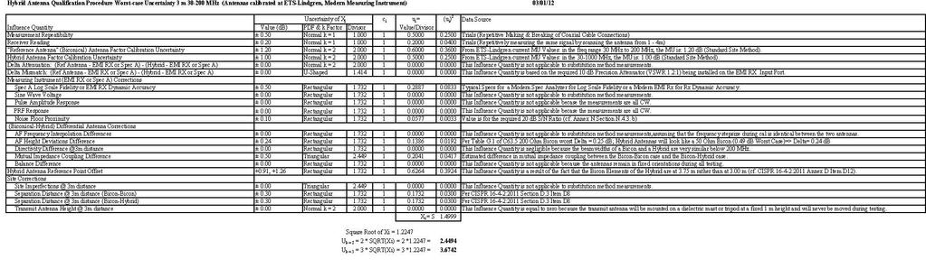
33 Example Spreadsheet 33
34 Qualification Interval (Section N.6) For any given hybrid antenna used at a given measurement distance, on a specific test site, the qualification process detailed in N.4 and N.5 shall be performed when the hybrid antenna is first taken into service at the given measurement distance on the specific test site, and subsequently at intervals of not more than three years. If damage to or degradation of the antenna is known or suspected to have occurred, a re-qualification is to be performed as well. 34
35 Some Hybrid Antennas that meet all of the Annex N Restrictions Schaffner (Chase) CBL 6116C Schaffner (Chase) CBL 6112B Teseq CBL 6112D Teseq CBL 6111D Electrometrics 6917C-1 ETS-Lindgren 3143B ETS-Lindgren 3149 Sunol JB1 Sunol JB2 Sunol JB6 Schwarzbeck VULB
36 Some Antennas that do NOT meet all of the Annex N Restrictions Electrometrics 6917B-1 (does not meet the minimum low frequency restriction) Schaffner CBL 9140A (does not meet the dimensional restrictions and the minimum frequency restrictions) Teseq CBL 6143A (does not meet the Emissions only/dual Use restriction) EMCO 3142B (does not meet the dimensional restrictions and the minimum frequency restrictions) EMCO 3142C (does not meet the dimensional restrictions and the minimum frequency restrictions) ETS-Lindgren 3142D (does not meet the dimensional restriction) Rohde & Schwarz HL562 (does not meet the dimensional restriction) A.H. Systems SAS (does not meet the minimum frequency restrictions) 36
US Council of EMC Laboratories [USCEL] Technical Issues having Significant Cost Implications for EMC Laboratory Owners/Operators
![US Council of EMC Laboratories [USCEL] Technical Issues having Significant Cost Implications for EMC Laboratory Owners/Operators](/thumbs/74/70107860.jpg "US Council of EMC Laboratories [USCEL] Technical Issues having Significant Cost Implications for EMC Laboratory Owners/Operators") US Council of EMC Laboratories [USCEL] Technical Issues having Significant Cost Implications for EMC Laboratory Owners/Operators Presented to the ACIL CAS EMC Committee On 17 August 2009 [Note: includes
US Council of EMC Laboratories [USCEL] Technical Issues having Significant Cost Implications for EMC Laboratory Owners/Operators Presented to the ACIL CAS EMC Committee On 17 August 2009 [Note: includes
Normalized Site Attenuation Test Report
 NVLAP LAB CODE 200974-0 Normalized Site Attenuation Test Report Test Specification NORMALIZED SITE ATTENUATION (NSA) Range 30 MHz 1GHz using the methods of ANSI C63.4-2009; EN 50147-2 (1997); CISPR 16-1-4
Test sites for EMC measurements
 Test sites for EMC measurements EMV Fachtagung 21. Januar 2014 Christophe Perrenoud www.montenaemc.ch montena emc Route de Montena 75 CH - 1728 Rossens Tel. +41 26 411 93 33 Fax +41 26 411 93 30 office.emc@montenaemc.ch
Ave output power ANT 1(dBm) Ave output power ANT 2 (dbm)
 Ave output power ANT 2 (dbm)") Page 41 of 103 9.6. Test Result The test was performed with 802.11b Channel Frequency (MHz) power ANT 1(dBm) power ANT 2 (dbm) power ANT 1(mW) power ANT 2 (mw) Limits dbm / W Low 2412 7.20 7.37 5.248 5.458
Page 41 of 103 9.6. Test Result The test was performed with 802.11b Channel Frequency (MHz) power ANT 1(dBm) power ANT 2 (dbm) power ANT 1(mW) power ANT 2 (mw) Limits dbm / W Low 2412 7.20 7.37 5.248 5.458
Title: Test on 5.8 GHz Band Outdoor WiFi (802.11b/g) Wireless Base Station
 Wireless Base Station") Page 20 of 51 Pages 7.5. Conducted spurious emission 7.5.1. Requirements: Clause 15.247(d). In any 100 khz bandwidth outside the frequency band in which the spread spectrum or digitally modulated intentional
Page 20 of 51 Pages 7.5. Conducted spurious emission 7.5.1. Requirements: Clause 15.247(d). In any 100 khz bandwidth outside the frequency band in which the spread spectrum or digitally modulated intentional
Tutorial on the Statistical Basis of ACE-PT Inc. s Proficiency Testing Schemes
 Tutorial on the Statistical Basis of ACE-PT Inc. s Proficiency Testing Schemes Note: For the benefit of those who are not familiar with details of ISO 13528:2015 and with the underlying statistical principles
Semi Anechoic Chamber (SAC)
") 1 of 9 Semi Anechoic Chamber (SAC) Approximate Dimensions of 3m Semi Anechoic Chamber (SAC) Length: 10m Width: 9m Height: 9m Frequency range of Semi Anechoic Chamber: 9 KHz to 40 GHz Emission test (EMI):
1 of 9 Semi Anechoic Chamber (SAC) Approximate Dimensions of 3m Semi Anechoic Chamber (SAC) Length: 10m Width: 9m Height: 9m Frequency range of Semi Anechoic Chamber: 9 KHz to 40 GHz Emission test (EMI):
Fully Anechoic Room Validation Measurements to CENELEC pren
 Fully Anechoic Room Validation Measurements to CENELEC pren517-3 M.A.K.Wiles*,W.Muellner** *ETS,Rochester,UK **Austrian Research Center,Seibersdorf,Austria Abstract Many small to medium sized EMC anechoic
This annex is valid from: to Replaces annex dated: Location(s) where activities are performed under accreditation
 where activities are performed under accreditation") Normative document: EN IS/IEC 17025:2005 Location(s) where activities are performed under accreditation Head ffice Vijzelmolenlaan 7 3447 GX oerden The Netherlands Location Abbreviation/ location Vijzelmolenlaan
Normative document: EN IS/IEC 17025:2005 Location(s) where activities are performed under accreditation Head ffice Vijzelmolenlaan 7 3447 GX oerden The Netherlands Location Abbreviation/ location Vijzelmolenlaan
Model 3180B Mini-Bicon Antenna User Manual
 Model 3180B Mini-Bicon Antenna User Manual Model 3180B with conical elements Model 3180B with cage elements ETS-Lindgren L.P. reserves the right to make changes to any product described herein in order
This annex is valid from: to Replaces annex dated: Location(s) where activities are performed under accreditation
 where activities are performed under accreditation") Location(s) where activities are performed under accreditation Head ffice Vijzelmolenlaan 7 3447 GX oerden The Netherlands Location Abbreviation/ location Vijzelmolenlaan 7 3447 GX oerden The Netherlands
Location(s) where activities are performed under accreditation Head ffice Vijzelmolenlaan 7 3447 GX oerden The Netherlands Location Abbreviation/ location Vijzelmolenlaan 7 3447 GX oerden The Netherlands
Version TEST REPORT NO. DATE DESCRIPTION
 Version NO. DATE DESCRIPTION HCTR1302FR13 February 14, 2013 - First Approval Report - Additional Model Name Page 2 of 25 Table of Contents 1. GENERAL INFORMATION... 4 2. EUT DESCRIPTION... 4 3. TEST METHODOLOGY...
Double-Ridged Waveguide Horn
 Model 3106 200 MHz 2 GHz Uniform Gain Power Handling up to 1.6 kw Model 3115 1 GHz 18 GHz Low VSWR Model 3116 18 GHz 40 GHz Quality Construction M O D E L 3 1 0 6 Double-Ridged Waveguide Horn PROVIDING
FCC CERTIFICATION TEST REPORT
 Report No:DDT-RE120176 Issued Date: 2013/01/05 FCC CERTIFICATION TEST REPORT FOR Applicant : AliMed Inc. Address : 297 High St Dedham Ma 02026 Equipment under Test : Alert transmitter Model No : #712716
Quality Auditing Institute # Schoolhouse Street, Coquitlam, BC, V3K 4X9, Canada. ISO Accreditation:
 CANADA: 16-211 Schoolhouse Street Coquitlam, British Columbia Canada V3K 4X9 ELECTROMAGNETIC COMPATIBILITY TEST REPORT TO CFR 47 FCC Part 15, Subpart C, Section 15.225 Industry Canada RSS 210, Issue 8
SHENZHEN LCS COMPLIANCE TESTING LABORATORY LTD. FCC ID: 2ADPC-G6 Report No.: LCS E
 2) Sequence of testing 30 to 1 GHz Setup: --- The equipment was set up to simulate a typical usage like described in the user manual or described by manufacturer. --- If the EUT is a tabletop system, a
Model BiConiLog Antenna. User Manual
 Model 3149 BiConiLog Antenna User Manual ETS-Lindgren Inc. reserves the right to make changes to any products herein to improve functioning or design. Although the information in this document has been
TABLE OF CONTENTS. 6. PHOTOGRAPH Photo of Conducted Emission Measurement Photo of Radiation Emission Measurement...
 TABLE OF CONTENTS 1. SUMMARY OF TEST RESULTS... 4 2. GENERAL INFORMATION... 5 2.1 Details of E.U.T.... 5 2.2 Description of Support Device... 5 2.3 Block Diagram of Test Setup... 5 2.4 Test Facility...
RADIO TEST REPORT. For MODEL NO FCC ID: C3K1703 IC ID: 3048A Test Report No. R-TR190-FCCIC-UNII-1 Issue Date: 14 September 2015
 RADIO TEST REPORT For MODEL NO. 1703 FCC ID: C3K1703 IC ID: 3048A-1703 Test Report No. R-TR190-FCCIC-UNII-1 Issue Date: 14 September 2015 FCC CFR47 Part 15 Subpart E Industry Canada RSS-247 Issue 1 Prepared
EXHIBIT 7: MEASUREMENT PROCEDURES Pursuant 47 CFR 2.947
 EXHIBIT 7: MEASUREMENT PROCEDURES Pursuant 47 CFR 2.947 7.1 RF Power -- Pursuant to 47 CFR 2.947(c) Method of Conducted Output Power Measurement: Adaptation of TIA/EIA-603-A clause 2.2.1 for Pulsed Measurements
L.S. Compliance, Inc. W66 N220 Commerce Court Cedarburg, WI
 L.S. Compliance, Inc. W66 N220 Commerce Court Cedarburg, WI 53012 262-375-4400 COMPLIANCE TESTING OF: Quartex Synchronization Transmitter Model FM-72 PREPARED FOR: Quartex, Division of Primex, Inc. 965
Selecting the right antenna for the
 Zhong Chen ETS-Lindgren EMC Antenna Fundamentals Selecting the right antenna for the job can be a difficult task. In many cases, manufacturer terminologies and specifications are so varied that it is difficult
Advanced Compliance Solutions, Inc FAU Blvd, Suite 310 Boca Raton, Florida (561)
") 2129.01 Advanced Compliance Solutions, Inc. 3998 FAU Blvd, Suite 310 Boca Raton, Florida 33431 (561) 961-5585 Technical Report No. 09-2067a-2 EMI Evaluation of the AMM Marketing, LLC s E-Pulse UH 900,
2129.01 Advanced Compliance Solutions, Inc. 3998 FAU Blvd, Suite 310 Boca Raton, Florida 33431 (561) 961-5585 Technical Report No. 09-2067a-2 EMI Evaluation of the AMM Marketing, LLC s E-Pulse UH 900,
EN 55015: 2013 Clause Pass. EN 55015: 2013 Clause Pass. EN 55015: 2013 Clause Pass
 Reference No.: WTD15S0730643E Page 2 of 42 1 Test Summary Test Item Conducted Disturbance at Mains Terminal, 9kHz to 30MHz Radiation electromagnetic disturbance, 9kHz to 30MHz Radiation Emission, 30MHz
EMC ANECHOIC CHAMBERS 5-METER CHAMBERS
 ETS-Lindgren's FACT 5 Chambers offer semi-anechoic radiated emissions (RE) and fully anechoic radiated immunity (RI) compliance test capability for most international EMC compliance regulations. FACT 5
Table of Contents 1. GENERAL INFORMATION SYSTEM TEST CONFIGURATION CONDUCTED EMISSIONS TEST RADIATED EMISSION TEST...
 Table of Contents 1. GENERAL INFORMATION... 4 1.1 PRODUCT DESCRIPTION FOR EQUIPMENT UNDER TEST... 4 1.2 RELATED SUBMITTAL(S) / GRANT (S)... 7 1.3 TEST METHODOLOGY... 7 1.4 EQUIPMENT MODIFICATIONS... 7
FCC REPORT. Dongguan Hele Electronics Co.,Ltd. * In the configuration tested, the EUT complied with the standards specified above.
 Report No.: GTS201708000040F02 FCC REPORT Applicant: Address of Applicant: Manufacturer: Dongguan Hele Electronics Co.,Ltd. Dalingya Industrial Zone,Daojiao Town,Dongguan City,Guangdong,China Dongguan
FCC REPORT. Dongguan Hele Electronics Co.,Ltd. * In the configuration tested, the EUT complied with the standards specified above.
 + Applicant: Address of Applicant: Manufacturer: FCC REPORT Dongguan Hele Electronics Co.,Ltd. Report No.: GTS201708000040F01 Dalingya Industrial Zone,Daojiao Town,Dongguan City,Guangdong,China Dongguan
FCC REPORT. Dongguan Hele Electronics Co., Ltd. J11, J12, J13, Q7, Q28, Q26, Q29
 FCC REPORT Applicant: Dongguan Hele Electronics Co., Ltd. Address of Applicant: Dalingya Industrial Zone, Daojiao Town, Dongguan City, Guangdong China Equipment Under Test (EUT) Product Name: Model No.:
REPORT REVISION HISTORY...
 Reference No.: WTS17S0579239E Page 2 of 39 2 Contents Page 1 COVER PAGE... 1 2 CONTENTS... 2 3 REPORT REVISION HISTORY... 3 4 GENERAL INFORMATION... 4 4.1 GENERAL DESCRIPTION OF E.U.T.... 4 4.2 DETAILS
FCC REPORT. 570 E1 Camino Real #200, Redwood City, CA 94063, United Manufacturer:
 FCC REPORT Applicant: Address of Applicant: Manufacturer: Striiv Inc. 570 E1 Camino Real #200, Redwood City, CA 94063, United States Striiv Inc. Address of 570 E1 Camino Real #200, Redwood City, CA 94063,
FCC ID: A3LSLS-BD106Q. Report No.: HCT-RF-1801-FC003. Plot Data for Output Port 2_QPSK 9 khz ~ 150 khz Middle channel 150 khz ~ 30 MHz Low channel
 Plot Data for Output Port 2_QPSK 9 khz ~ 150 khz Middle channel 150 khz ~ 30 MHz Low channel 30 MHz ~ 1 GHz Middle channel 1 GHz ~ 2.491 GHz Low channel 2.695 GHz ~ 12.75 GHz High channel 12.75 GHz ~ 26.5
Model 3140B BiConiLog Antenna User Manual
 Model 3140B BiConiLog Antenna User Manual Model 3140B mounted onto a 7-TR tripod (not included) ETS-Lindgren L.P. reserves the right to make changes to any product described herein in order to improve
FCC PART TEST REPORT. Weccan Industrial Limited
 FCC PART 15.249 TEST REPORT For Weccan Industrial Limited Rm209, 2/F, Building W1-A, No.34 Gaoxin South 4th St Hi-Tech Industrial Park, Nanshan District, Shenzhen China FCC ID: Z3CWECCANDRONE Report Type:
FCC TEST REPORT. for. 47 CFR, Part 15, Subpart C. SPORTON International Inc.
 FCC TEST REPORT for 47 CFR, Part 15, Subpart C Equipment Trade Name Model No. FCC ID Filing Type Applicant : GamePad : Genius : Wireless G-12X : FSUGG0005 : Certification : KYE Systems Corp. No. 492, Sec.
Electromagnetic Compatibility ( EMC )
") Electromagnetic Compatibility ( EMC ) Introduction EMC Testing 1-2 -1 Agenda System Radiated Interference Test System Conducted Interference Test 1-2 -2 System Radiated Interference Test Open-Area Test
Electromagnetic Compatibility ( EMC ) Introduction EMC Testing 1-2 -1 Agenda System Radiated Interference Test System Conducted Interference Test 1-2 -2 System Radiated Interference Test Open-Area Test
Archived 3/18/10 USER MANUAL EMCO MODEL 3141 BICONILOG TM LOG-PERIODIC / T BOW-TIE ANTENNA Rev A 01/97
 USER MANUAL EMCO MODEL 3141 BICONILOG TM LOG-PERIODIC / T BOW-TIE ANTENNA 399236 Rev A 01/97 GENERAL DESCRIPTION The EMCO Model 3141 is the latest evolution in the popular bow-tie/log periodic combination
FCC 47 CFR PART 15 SUBPART B TEST REPORT SHENZHEN EAGLE TECHNOLOGY CO., LTD Mirror photo booth Model No.: EAGMR
 FCC 47 CFR PART 15 SUBPART B TEST REPORT SHENZHEN EAGLE TECHNOLOGY CO., LTD Mirror photo booth Model No.: EAGMR Prepared for Address : SHENZHEN EAGLE TECHNOLOGY CO., LTD : A FIoor 1 BIdg.14, Changfeng
Measurement of RF Emissions from a Caterpillar Inc. MSS3s RF ID Key Fob
 Measurement of RF Emissions from a Caterpillar Inc. MSS3s RF ID Key Fob For Caterpillar Inc. 330 S.W. Adams Street Peoria, IL 61630 P.O. Number JBL 11260 Date Tested May 11, 2016 Test Personnel Mark Longinotti
FCC 47 CFR PART 15 SUBPART C AND ANSI C63.10:2013 TEST REPORT
 FCC 47 CFR PART 15 SUBPART C AND ANSI C63.10:2013 TEST REPORT For ZigBee Module Model: MD1000 Trade Name: Billion Issued for Billion Electric Co., Ltd. 8F., No.192, Sec. 2, Zhongxing Rd., Xindian Dist.,
7. Transmitter Radiated Spurious Emissions and Conducted Spurious Emission
 7. Transmitter Radiated Spurious Emissions and Conducted Spurious Emission 7.1 Test Setup Refer to the APPENDIX I. 7.2 Limit According to 15.247(d), in any 100 khz bandwidth outside the frequency band
FCC REPORT. Lightcomm Technology Co., Ltd.
 FCC REPORT Report No.: GTS201608000267E01 Applicant: Lightcomm Technology Co., Ltd. Address of Applicant: RM 1808 18/F FO TAN INDUSTRIAL CENTRE NOS. 26-28 AU PUI WAN STREET FO TAN SHATIN NEW TERRITORIES
ACCREDITED LABORATORY. LIBERTY LABS, INC. Kimballton, IA for technical competence in the field of Calibration
 THE AMERICAN ASSOCIATION FOR LABORATORY ACCREDITATION ACCREDITED LABORATORY A2LA has accredited LIBERTY LABS, INC. Kimballton, IA for technical competence in the field of Calibration The accreditation
A Study of Conducted-Emission Stable Source Applied to the EMC US and EU Standards
 Fourth LACCEI International Latin American and Caribbean Conference for Engineering and Technology (LACCEI 2006) Breaking Frontiers and Barriers in Engineering: Education, Research and Practice, 21-23
FCC Test Report. Report No.: PTCDQ FC01
 Page 1 of 63 FCC Test Report Report No.: PTCDQ04170450501-FC01 FCC ID : 2AL2XW801 APPLICATION PURPOSE : Original Equipment PRODUCT DESIGNATION : WIFI DoorBell BRAND NAME : EASTIC MODEL NAME : W801, W802,
ANSI C Testing unintentional emitters
 ANSI C63.4-2014 Testing unintentional emitters Presented by Don Heirman President Don Lincroft, New Jersey USA Chair, ANSI C63.4 Working Group March 2015 Slide 1 Use of colors on slides Generally text
Electromagnetic Compatibility Test Report FCC test results of an automatic dog brush, model EUT: Type 1 AC/DC adaptor: SYS W2E
 Electromagnetic Compatibility Test Report FCC test results of an automatic dog brush, model EUT: Type 1 AC/DC adaptor: SYS1308-1809-W2E Customer Customer's representative In the capacity of Reference number
Radiated Spurious Emission Testing. Jari Vikstedt
 Radiated Spurious Emission Testing Jari Vikstedt jari.vikstedt@ets-lindgren.com What is RSE? RSE = radiated spurious emission Radiated chamber Emission EMI Spurious intentional radiator 2 Spurious Spurious,
Log Periodic Dipole Array Antenna
 Model 3148B Log Periodic Dipole Array Antenna User Manual ETS-Lindgren L.P. reserves the right to make changes to any product described herein in order to improve function, design, or for any other reason.
FCC 47 CFR PART 15 SUBPART B TEST REPORT KST DIGITAL TECHNOLOGY LIMITED. Brushless Servo
 FCC 47 CFR PART 15 SUBPART B TEST REPORT KST DIGITAL TECHNOLOGY LIMITED Brushless Servo Model No.: X20-3612 Additional Model No.: X20-1035, X20-2208, X20-3012, X20-9650, BLS159, BLS651, BLS259, BLS359,
FCC 15B Test Report. : BTv4.0 Dual Mode USB Dongle. Address : Thompson Ave. / Lenexa, Kansas / / USA
 FCC 15B Test Report Equipment Model No. Brand Name Applicant : BTv4.0 Dual Mode USB Dongle : BT820 : Laird Technologies : Laird Technologies Address : 11160 Thompson Ave. / Lenexa, Kansas / 66219 / USA
Nemko Canada Inc., 303 River Road, R.R. 5, Ottawa, Ontario, Canada, K1V 1H2
 www.nemko.com Nemko Canada Inc., 303 River Road, R.R. 5, Ottawa, Ontario, Canada, K1V 1H2 Report Number: Product Marketing Name: 123766-1TRFEMC Paycheck 4 Thermal Ticket Printer Test Specification: FCC
SAS Log Periodic Antenna Operation Manual
 SAS-512-2 Log Periodic Antenna Operation Manual 1 TABLE OF CONTENTS INTRODUCTION Introduction...3 Intended Purposes...4 Optional Equipment...5 OPERATING INSTRUCTIONS Assembly Instructions...6 Mounting
F C C - TESTREPORT REPORT NO.: FCC-02/
 F C C - TESTREPORT REPORT NO.: FCC-02/09-0010 pkm Ohmstrasse 1 D-84160 Frontenhausen Tel : 08732-6381 Fax : 08732-2345 e-mail: pkm.accredited-labs@t-online.de Seite/page: 2 of 12 TABLE OF CONTENTS Page
Alternative Radiated Emission Measurements at Close Distance In Industry
 Alternative Radiated Emission Measurements at Close Distance In Industry Osman Şen, Bahadır Tektaş, Soydan Çakır, Mustafa Çetintaş Electromagnetic Laboratories, TUBITAK UME, Gebze, Kocaeli, Turkey Abstract
Spurious Emissions & Emission Mark Report
 Spurious Emissions & Emission Mark Report for the SRT Marine Technology Ltd Neon 403-0001 AIS Class B Transceiver No. Issue#1: 20 th July 2009 EU Notified Body FCC & VCCI Registered BSMI Lab ID: SL2-IN-E-3008
FCC Part 15 Subpart B
 Report No.: 15A111603E-F Page 1 of 23 Test Report FCC Part 15 Subpart B for Electromagnetic Interference of Product: Managed PoE Industrial Ethernet Switch Trade Name: N/A Model Number: IS-DG512P-2F-8;
Revision history. Revision Date of issue Test report No. Description KES-RF-14T0042 Initial
 Page (2 ) of (34) Revision history Revision Date of issue Test report No. Description - 2014.08.25 Initial Page (3 ) of (34) TABLE OF CONTENTS 1. General information... 4 1.1. EUT description... 4 1.2.
Measurement of RF Interference from a Canopy 900MHz Access Point and Subscriber Module Using A Yagi Antenna
 Measurement of RF Interference from a Canopy 900MHz Access Point and Subscriber Module Using A Yagi Antenna For : Motorola, Inc. 1301 East Algonquin Road Schaumburg, IL 60196 P.O. No. : 40335 Date Tested
SAC-10 Plus Triton Class
 Anechoic Chamber SAC-10 Plus Triton Class SAC-10 Plus Triton Class Frankonia s anechoic chamber for 10.0 & 3.0 m measuring distance with triple test axes FRANKONIA CONCEPT SAC-10 Plus Triton Class Frankonia
STC Test Report. Date : Page 1 of 13 No. : HM161169
 Date : 2009-05-11 Page 1 of 13 Applicant (ATS001): Atech Scientific Measurement Limited. Room A-C, 18 Floor, Luk Hop Ind. Bldg, 8 Luk Hop Street, Kowloon Manufacturer: Atech Scientific Measurement Limited.
FCC Rules and Regulations / Intentional Radiators. Operational in the MHz, MHz, MHz, and
 FCC Rules and Regulations / Intentional Radiators Operational in the 902-928 MHz, 2400-2483.5 MHz, 5725-5875 MHz, and 24.0-24.25 GHz Bands Part 15, Subpart C, Section 15.249 THE FOLLOWING MEETS THE ABOVE
Measurement Procedure & Test Equipment Used
 Measurement Procedure & Test Equipment Used Except where otherwise stated, all measurements are made following the Electronic Industries Association (EIA) Minimum Standard for Portable/Personal Land Mobile
Verification of Conformity On Behalf of
 Verification of Conformity On Behalf of EVERPRO TECHNOLOGIES COMPANY LTD. HDMI Active optical Cable Model No.: HDMI OPTICAL FIBER CABLE 330FT, 300FT, 250FT, 200FT, 150FT, 100FT, 50FT Prepared for : EVERPRO
Global United Technology Services Co., Ltd. SPECTRUM REPORT SHENZHEN WLINK TECHNOLOGY CO., LIMITED
 Report No.: GTS201712000042E02 SPECTRUM REPORT Applicant: Address of Applicant: Manufacturer/Factory: SHENZHEN WLINK TECHNOLOGY CO., LIMITED 319, YiBen Electronic Business Building, NO.1063 ChaGuang Road,
FCC & IC Certification. Test Report. FCC & Industry Canada Certification. Test Report. for Hetronic USA FCC ID: LW9-CS434TXN IC ID: 2219A-CS434TXN
 FCC & IC Certification Test Report FCC & Industry Canada Certification Test Report for Hetronic USA March 3, 2005 Prepared for: Hetronic USA 4300 Highline Blvd Building 4 Oklahoma City, OK 73108 Prepared
Channel 01 (2422MHz)
") Product : PC to TV Transmitter [u17] Test Item : RF Antenna Conducted Spurious Test Site : No.3 OATS Test Mode : Mode 4: Transmit (802.11n MCS0 15Mbps 40M-BW) Channel 01 (2422MHz) Page: 57 of 109 Page:
Product : PC to TV Transmitter [u17] Test Item : RF Antenna Conducted Spurious Test Site : No.3 OATS Test Mode : Mode 4: Transmit (802.11n MCS0 15Mbps 40M-BW) Channel 01 (2422MHz) Page: 57 of 109 Page:
FCC Test Report. Report No.: AGC FE08. Attestation of Global Compliance (Shenzhen) Co., Ltd
 Co., Ltd") Page 1 of 27 FCC Test Report Report No.: AGC01039170608FE08 FCC ID : PODTYT-X1U TYPE OF AUTHORIZATION : Certification APPLICATION PURPOSE : Original Equipment PRODUCT DESIGNATION : Analog Transceiver BRAND
Page 1 of 27 FCC Test Report Report No.: AGC01039170608FE08 FCC ID : PODTYT-X1U TYPE OF AUTHORIZATION : Certification APPLICATION PURPOSE : Original Equipment PRODUCT DESIGNATION : Analog Transceiver BRAND
T E S T - R E P O R T. Test Report No (Edition 1) for RF340-R. Inductive Tag Reader
 for RF340-R. Inductive Tag Reader") Straubing, 27 February 2006 T E S T - R E P O R T No. 51905-060004-7 (Edition 1) for RF340-R Inductive Tag Reader Applicant: Siemens AG A&D PT7 D2 Test Specifications: FCC Code of Federal Regulations,
Straubing, 27 February 2006 T E S T - R E P O R T No. 51905-060004-7 (Edition 1) for RF340-R Inductive Tag Reader Applicant: Siemens AG A&D PT7 D2 Test Specifications: FCC Code of Federal Regulations,
TRFWL. Autostart Inc Rue Paré Mont-Royal, Québec Canada, H4P 2M2 EZSNAH2503
 Nemko Test Report: 109054-1TRFWL Applicant: Autostart Inc. 5764 Rue Paré Mont-Royal, Québec Canada, H4P 2M2 Apparatus: ASRA 2503 FCC ID: EZSNAH2503 In Accordance With: FCC Part 15 Subpart B, 15.107 and
Dongguan Nore Testing Center Co., Ltd. Report No.: NTC F TABLE OF CONTENTS
 TABLE OF CONTENTS 1. SUMMARY OF TEST RESULTS... 4 2. GENERAL INFORMATION... 5 2.1 Details of E.U.T.... 5 2.2 Description of Support Device... 5 2.3 Block Diagram of Test Setup... 5 2.4 Test Facility...
TDS-535 Tuned Dipole Set Operation Manual
 TDS-535 Tuned Dipole Set Operation Manual 1 TABLE OF CONTENTS INTRODUCTION Antenna Set Contents...3 Intended Purposes...4 Range of Environmental Conditions...5 GENERAL INSTRUCTIONS General Description...5
For. Unit D16/F. should not use it to claim FCC ID: 2AAIN-MNGLOS
 Page 1 of 49 TESTT REPORT For Applicant : ACOUSTMAX INTERNATIONAL CO.., LTD Unit D16/F Cheuk Nang Plaza 250 Hennessy Road Address : WanchaiHongKong Product Name : Monster GLO Model Name : MNGLO-S, MNGLO-L,MNGLO-M,MNGLO-Mini
Double-Ridged Waveguide Horn
 Established 1981 Advanced Test Equipment Rentals www.atecorp.com 800-404-ATEC (2832) EMC Antennas 3-D Patterns Available at /3117 FEATURES: Ultra Broadband: 1 GHz - 18 GHz Maintains Single Lobe Radiation
ETS Lindgren Anechoic Chamber
 ETS Lindgren Anechoic Chamber Provides an electromagnetically quiet environment for measuring the radiating properties of a device-undertest Enclosed by an external metallic shielding to provide isolation
FCC TEST REPORT On Behalf of GZTOD.CO., LTD The Multifunctional Platooninsert Model No.: YA30WSL-6AU6U
 FCC TEST REPORT On Behalf of GZTOD.CO., LTD The Multifunctional Platooninsert Model No.: YA30WSL-6AU6U Prepared for Address : GZTOD.CO., LTD : 2-5/F, Building A4, Huimingsheng Industrial Park, Tongfuyu
FCC PART 15C TEST REPORT FOR CERTIFICATION On Behalf of. Trade Name : Activision. Model Number: / FCC ID: XLU
 FCC PART 15C TEST REPORT FOR CERTIFICATION On Behalf of Activision Publishing, Inc USB Wireless Receiver for Wii & USB Wireless Receiver for PS3 Trade Name : Activision. Model Number: 83973791/84148791
SCOPE OF ACCREDITATION TO ISO/IEC 17025:2005. TOKIN EMC ENGINEERING CO., LTD Hanashimashinden, Tsukuba-shi, Ibaraki Japan
 SCOPE OF ACCREDITATION TO ISO/IEC 17025:2005 TOKIN EMC ENGINEERING CO., LTD. 28-1 Hanashimashinden, Tsukuba-shi, Ibaraki 305-0875 Japan Masato Morooka - Tomio Koyama - Authorized Representative Deputy
416 Maetan 3-Dong, Yeongtong-Gu, Suwon-Si, Gyeonggi-Do, Korea,
 EMC TEST REPORT According to FCC CFR47 Part 18 Subpart C JOB Number : LBE20110882 1. This test report does not constitute an endorsement by NIST/NVLAP or U.S Government. 2. This test report is to certify
MANUAL. PCD - Precision Conical Dipole Antenna
 MANUAL PCD - Precision Conical Dipole Antenna RF Engineering MANUAL Precision Conical Dipole Antenna 12.10.2009 Version 2.0 Notice Seibersdorf Labor GmbH reserves the right to make changes to any product
TEST REPORT. Power Spout PLT V. tested to the specification. EN : Amendment 1: Electromagnetic compatibility (EMC)
") EMC Technologies (NZ) Ltd PO Box 68-307, Newton Auckland 1145 New Zealand Phone 09 360 0862 Fax 09 360 0861 E-Mail Address: aucklab@ihug.co.nz Web Site: www.emctech.com.au TEST REPORT Power Spout PLT 100
EMC Technologies (NZ) Ltd PO Box 68-307, Newton Auckland 1145 New Zealand Phone 09 360 0862 Fax 09 360 0861 E-Mail Address: aucklab@ihug.co.nz Web Site: www.emctech.com.au TEST REPORT Power Spout PLT 100
INTERNATIONAL STANDARD
 INTERNATIONAL STANDARD IEC 60489-1 1983 AMENDMENT 2 1999-05 Amendment 2 Methods of measurement for radio equipment used in the mobile services Part 1: General definitions and standard conditions of measurement
FCC TEST REPORT. Table of Contents. Report no. ETLE , Page 2 of 21
 Table of Contents FCC Measurement Report 1. Introduction 2. Product Information 3. Description of Tests 4. Test Condition 5. Test Results 5.1 Summary of Test Results 5.2 Conducted Emissions Measurement
FCC CFR47 PART 15 SUBPART C INDUSTRY CANADA RSS-GEN AND RSS-210 CERTIFICATION TEST REPORT FOR BROADCOM BLUETOOTH MODULE MODEL NUMBER: BCM92046MD
 FCC CFR47 PART 15 SUBPART C INDUSTRY CANADA RSS-GEN AND RSS-210 CERTIFICATION TEST REPORT FOR BROADCOM BLUETOOTH MODULE MODEL NUMBER: BCM92046MD IC #: 4324A-BRCM1029 REPORT NUMBER: 07U11199-1C ISSUE DATE:
TEST SUMMARY. Prüfbericht - Nr.: Test Report No FIELD STRENGTH OF FUNDAMENTAL RESULT: Passed % BANDWIDTH RESULT: Passed
 Seite 2 von 24 Page 2 of 24 TEST SUMMARY 5.1.1 FIELD STRENGTH OF FUNDAMENTAL RESULT: Passed 5.1.2 99% BANDWIDTH RESULT: Passed 5.1.3 SPURIOUS EMISSION RESULT: Passed 5.2.1 SPURIOUS EMISSION RESULT: Passed
FCC PART MEASUREMENT AND TEST REPORT FOR. Guangzhou Walkera Technology CO., LTD
 FCC PART 15.249 MEASUREMENT AND TEST REPORT FOR Guangzhou Walkera Technology CO., LTD Taishi Industrial Park, Yuwoto Town, Panyu District, 511475 Guangzhou, China. FCC ID: S29WK-2801PRO Report Concerns:
Laird Attn: Bill Steinike W66 N220 Commerce Ct. Cedarburg, WI Report Constructed by: Zach Wilson, EMC Technician Signature: Date: June 21, 2017
 A Test Report # 317241 Equipment Under Test: RM024 Test Date(s): June 9 and June 21, 2017 Prepared for: Laird Attn: Bill Steinike W66 N220 Commerce Ct. Cedarburg, WI 53012 Report Issued by: Adam Alger,
EMI T E S T R E P O R T
 EMI T E S T R E P O R T - FCC Part 15B - Test Report No. : T38935-00-02TK 27. November 2014 Date of issue Type / Model Name : One Touch Select Plus Flex Product Description : Blood glucose meter with Bluetooth
FCC ID: B4OCC264BPA-S
 FCC TEST REPORT FCC ID: B4OCC264BPA-S Product : Bluetooth LE Module Model Name : CC264BPA-S, CC265BPA-S, CC26xBPA Brand : GT-tronics Report No. : PTC801181160622E-FC01 Prepared for GT-tronics HK Ltd Unit
FCC REPORT. 2AKQO-Q740 FCC CFR Title 47 Part 15 Subpart C. * In the configuration tested, the EUT complied with the standards specified above.
 FCC REPORT Applicant: Address of Applicant: Manufacturer/Factory: Address of Manufacturer/Factory: Guangzhou Smamao Electronic Technology Co.,Ltd Room 811, Building 8, No.315, Central City, Middle Road,
FCC CFR47 PART 15 SUBPART C INDUSTRY CANADA RSS-210 ISSUE 8 CERTIFICATION TEST REPORT FOR FOB ASSY BIDIRECTIONAL R/C MODEL NUMBER: GHW-H001
 FCC CFR47 PART 15 SUBPART C INDUSTRY CANADA RSS-210 ISSUE 8 CERTIFICATION TEST REPORT FOR FOB ASSY BIDIRECTIONAL R/C MODEL NUMBER: GHW-H001 REPORT NUMBER: 32AE0249-SH-B-R1 ISSUE DATE: September 28, 2011
Electrical Field Distribution*
 Features l 30 MHz to MHz frequency range l Wide beamwidth illuminates a large uniform area l High power balun handles up to 10 kw RF input power l Tilt-angle, height and polarization are easily adjustable
CENTRE OF TESTING SERVICE INTERNATIONAL
 CENTRE OF TESTING SERVICE INTERNATIONAL OPERATE ACCORDING TO ISO/IEC 17025 FCC TEST REPORT TEST REPORT NUMBER : CGZ3150202-00097-E A101,No.65,Zhuji Highway,Tianhe District,Guangzhou, Guangdong, China Report
AK-18G Antenna Kit Operation Manual
 AK-18G Antenna Kit Operation Manual 1 TABLE OF CONTENTS WARRANTY 3 INTRODUCTION 4 GENERAL INFORMATION 5 OPTIONAL EQUIPMENT 8 FORMULAS 9 MAINTENANCE 10 2 WARRANTY INFORMATION A.H. Systems Inc., warrants
Compliance Engineering Ireland Ltd
 Page 1 of 27 Compliance Engineering Ireland Ltd RAYSTOWN, RATOATH ROAD, ASHBOURNE, CO. MEATH, IRELAND Tel: +353 1 8256722 Fax: +353 1 8256733 Project Number: 10E2475-5 Prepared for: Biancamed Ltd By Compliance
ITL Page 2 of 71 Report No.:
 ITL Page 1 of 71 Report No.: 12092752 TEST REPORT Applicant: Address of Applicant: Harman International Industries, Incorporated 8500 Balboa Blvd, Northridge, CA 91329, United States Manufacturer: Address
SCOPE OF ACCREDITATION TO ISO/IEC 17025:2005 & ANSI/NCSL Z
 SCOPE OF ACCREDITATION TO ISO/IEC 17025:2005 & ANSI/NCSL Z540-1-1994 ETS-LINDGREN INC. 1301 Arrow Point Drive Cedar Park, TX 78613 Ron Bethel Phone: 512 531 6400 CALIBRATION Valid To: December 31, 2018
Shielding Effectiveness Summary Results for RadiaShield Technologies, Inc. RadiaShield Fabric
 Test Date(s): July 9 through July 19, 2010 UST Project Number: 10-0164 Summary Results for Product Description The Sample Under Test (SUT) is the. The SUT is a textile which is used as a protective shield
Declaration of Conformity (DoC)
") Declaration of Conformity (DoC) Per 47 CFR 2.1077(a) & 15.19(a)(3) The following device is herewith confirmed to comply with Part 15 of the FCC Rules. Product Name : PCIE-USB380,PCIE-USB340 Model No. :
Declaration of Conformity (DoC) Per 47 CFR 2.1077(a) & 15.19(a)(3) The following device is herewith confirmed to comply with Part 15 of the FCC Rules. Product Name : PCIE-USB380,PCIE-USB340 Model No. :
Proposed TDR Method for Site Validation Above 1 GHz
 Proposed TDR Method for Site Validation Above 1 GHz ACIL CAS Meeting August 15, 2011 Long Beach, CA by Greg Kiemel, Director of Engineering gkiemel@nwemc.com Northwest EMC, Inc. www.nwemc.com Overview