MANUAL. PCD - Precision Conical Dipole Antenna
|
|
|
- Barnaby Leonard
- 6 years ago
- Views:
Transcription

1 MANUAL PCD - Precision Conical Dipole Antenna
2
3 RF Engineering MANUAL Precision Conical Dipole Antenna Version 2.0
4 Notice Seibersdorf Labor GmbH reserves the right to make changes to any product described herein in order to improve function, design or for any other reason. Nothing contained herein shall constitute Seibersdorf Labor GmbH assuming any liability whatsoever arising out of the application or use of any product or circuit described herein. All graphs show typical data and not the measurement values of the individual product delivered with this manual. Seibersdorf Labor GmbH does not convey any license under its patent rights or the rights of others. Precision Conical Dipole Antenna, PCD, Antenna, CalStan/10.0 are products of Seibersdorf Labor GmbH Copyright by Seibersdorf Labor GmbH. All Rights Reserved. No part of this document may be copied by any means without written permission from Seibersdorf Labor GmbH Contact Seibersdorf Labor GmbH RF Engineering T +43(0) F +43(0) rf@seibersdorf-laboratories.at VAT no.: ATU , Company no v, DVR no Bank account: Erste Bank, sort code 20111, account no PRECISION CONICAL ANTENNA MANUAL SEIBERSDORF LABORATORIES
5 Table of Contents 1. PRODUT DESCRIPTION SPECIFICATIONS General Technical data for PCD Technical data for PCD SETS AND OPTIONS OPERATION Mounting the PCD on an Antenna Mast Operating Precautions MEASUREMENTS Simple Field Strength Measurements Free Space Site Attenuation Measurements EMF Field Strength Measurements (Field Nose) WARRANTY SEIBERSDORF LABORATORIES PRECISION CONICAL ANTENNA MANUAL 3
6 4 PRECISION CONICAL ANTENNA MANUAL SEIBERSDORF LABORATORIES
7 1. PRODUT DESCRIPTION The Seibersdorf Labor GmbH Precision Conical Dipole Antenna PCD are ultra broadband antennas for: Site validation measurements according to CISPR in fully anechcoic rooms. Exposure evaluation next to mobile communication facilities (e.g. base stations) Accurate RF radiation safety measurements (e.g. broadcast stations) All purposes of broadband precision field-strength measurements. 2. SPECIFICATIONS 2.1. General Humidity: Temperature of operation: Power, damage level Field strength, damage level Connector type: Protect this product against water and temperature extremes which can cause internal condensation. +10 C to +40 C +20 dbm 100 V/m SMA female 2.2. Technical data for PCD3100 Frequency range: Dimensions: 30 MHz 1 GHz Antenna width: 21 cm total Support length: 15 cm 2.3. Technical data for PCD8250 Frequency range: Dimensions: 80 MHz 3 GHz Antenna width: 13 cm total Support length: 15 cm SEIBERSDORF LABORATORIES PRECISION CONICAL ANTENNA MANUAL 5
8 55 Antenna Factor [db/m] PCD 8250 PCD Frequency [MHz] Figure 1: Typical antenna factor of PCD antennas PCD 8250 PCD 3100 VSWR Frequency [MHz] Figure 2: Typical VSWR of PCD antennas 6 PRECISION CONICAL ANTENNA MANUAL SEIBERSDORF LABORATORIES


")
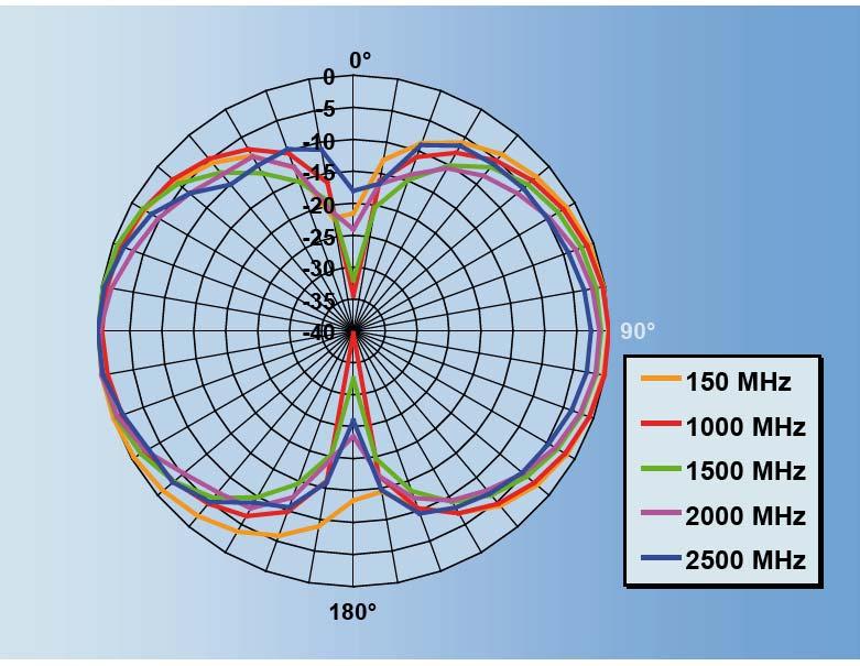
9 Figure 3: Typical radiation pattern of PCD 8250 antenna (E-Plane) SEIBERSDORF LABORATORIES PRECISION CONICAL ANTENNA MANUAL 7
10 3. SETS AND OPTIONS NB1 NO1 NO2 NO5 NO6 NO7 NO8 NO9 NO10 NO11 NO12 NO13 NO15 NO16 AO1 RO5 Field Nose Basic package, 80 MHz 3 GHz Antenna PCD8250 with calibration (A2Fj), automatic antenna rotator, coaxial cable with ÖKD certificate (L1a), measurement software NOSE Basic, SW-documentation, all packed in one transportation case. Alternative large antenna elements for PCD8250 to change the frequency range of this antenna to 30 MHz 1 GHz, delivered with typical antenna factor. For precise measurements we recommend to order an individual calibration according our CALIBRATIONS pricelist (A2i). Automatic PCD antenna rotator, frequency range is 10 MHz to 3 GHz with N-female connector and ¼ mount for tripods. The rotator is controlled and powered via USB (5 m USB cable included) by PC and delivered with an ÖKD certificate for the integrated cable. Coaxial cable, 10 MHz 3 GHz, length 5 m, N-male connectors and traceable ÖKD calibration of cable attenuation. Coaxial cable, 10 MHz 3 GHz, length 10 m, N-male connectors and traceable ÖKD calibration of cable attenuation. Ferrite beaded coaxial cable, 10 MHz 3 GHz, length 10 m, N-male/SMA-male connectors, including traceable ÖKD cable loss calibration. Coaxial cable, 100 MHz 18 GHz, length 5 m, SMA-male/N-female connectors and traceable ISO calibration of cable attenuation. Rf-adapter, N/SMA, SMA/SMA or N/N each plug either male or female. Please specify exactly within your order. Manual antenna rotator for field strength measurements in three orthogonal directions. The rotator can be fixed on tripods with 1/4'' mount. Antenna holder to mount a PCD antenna in horizontal or vertical polarisation on a tripod (1/4'' mount). Wooden tripod, height of antenna with manual or automatic antenna rotator is from 1 m to 2 m, transport size: 65 cm x 13 cm x 13 cm, weight: 3 kg Transportation case for PCD8250, a rotator and cables. Measurement software NOSE Pro for control of spectrum analyser and automatic antenna rotator, for ambitious measurement tasks, long term measurements and advanced evaluations of measurement data. Upgrade of Software NOSE Pro for NOSE Basic users. PCD antenna case, transportation case for PCD3100 or PCD8250 antenna, additional PCD radiation elements and cables. Antenna coupler CU8250 for precise system check with PCD3100 or PCD8250 antennas. 8 PRECISION CONICAL ANTENNA MANUAL SEIBERSDORF LABORATORIES
11 SW4 SW6 NSA FAR module for CalStan 10.0 software NSA for fully anechoic rooms according to following standards and procedures: CISPR ed (Site Reference), CISPR ed (NSA method), Seibersdorf Transmission Loss Method. Experimental measurement module for CalStan 10.0 software measurement of RF Power Level, Field Strength, S11, S21 with additional control of signal generator and antenna mast if applicable for customer specific applications (e.g. Ambient Noise, Table influence, ). SEIBERSDORF LABORATORIES PRECISION CONICAL ANTENNA MANUAL 9
12 4. OPERATION 4.1. Mounting the PCD on an Antenna Mast You can use the W ¼ inch thread on the bottom of the mounting base. The thread length of the used W ¼ inch screws must be less than 12 mm. Otherwise the cable inside the mounting base will be damaged. For convenient operation of the PCD in horizontal and vertical polarisation we recommend to use the optionally available H+V (horizontal and vertical) antenna holder. For field strength measurements with omnidirectional characteristic we recommend our Field Nose Basic system (see chapter 5.3). The special Add3D holder and rotator together with the control software realises the three orthogonal positions by simple turns of 120 of the holder on his platform. For accurate measurements, it is very important to keep conductive and massive dielectric parts away from the PCD. Therefore, please mount the antenna always on non-metallic platforms. To achieve the best performance, do not mount the PCD on the plastic supports of your antenna mast directly. Use polystyrene foam as support where applicable. 10 PRECISION CONICAL ANTENNA MANUAL SEIBERSDORF LABORATORIES
13 4.2. Operating Precautions Never operate the product outside of specifications Never use ¼ inch threads longer than 12 mm to fix the mounting base on any mast Never apply any kind of mechanical stress or shock to any part of this product Do not open the balun boxes or the antenna mounting bases. This could result in damage or reduced electrical performance and accuracy After using this product, please store it in the supplied case Prevent from dust, dirt and water Temperature of operation: 10 C to 40 C Maximum input power: 20dBm Maximum field strength: 100 V/m SEIBERSDORF LABORATORIES PRECISION CONICAL ANTENNA MANUAL 11
14 5. MEASUREMENTS For doing accurate measurements, it is very important to keep conductive and massive dielectric elements away from the PCD, especially at higher frequencies. Always mount the dipoles on non-metallic platforms. For best performance do not mount the PCD on large and massive plastic supports. Use polystyrene foam when no proper antenna holder is available. Hint: An additional attenuator (minimum 3dB) at the balun output should be used to reduce the uncertainty caused by mismatch error. Hint: To reduce secondary radiation from the antenna cable a ferrite beaded cable should be used. This cable is optionally available in 5 m and 10 m length Simple Field Strength Measurements To indicate the field strength, the antenna factor, the cable loss and the matching pad attenuation have to be added to the receiver reading. E[dBµV/m] = U receiver [dbµv] + AF PCD [db/m] + ATT cable [db] + ATT attenuator [db] (1) 5.2. Free Space Site Attenuation Measurements To validate fully anechoic EMC test chambers according to CISPR a small transmit antenna with dipole like characteristic and a maximum dimension of 40 cm is required. The PCD 3100 is suited best for this type of measurements. The measurements of the Freespace Normalized Site Attenuation (FSNSA) are done in the frequency range from 30 MHz to 1 GHz with broadband antennas in horizontal and vertical polarisation in the fully anechoic chamber. The volumetric test method is applied. The transmit antenna is placed at 5 measurement positions in 3 heights and 2 polarisations. The receive antenna is kept in a constant distance in the height of the center plane and adjusted (tilted) in direction of the receive antenna. A precise calibration of the antennas is required. Figure 4 shows the setup. 12 PRECISION CONICAL ANTENNA MANUAL SEIBERSDORF LABORATORIES
15 a) d offset d walkable floor d offset h lower plane middle plane upper plane floor absorbers shielding b) d d v d fixed distance d c) Reference point Log.per. antenna Biconical antenna Figure 4: Measurement positions in the test volume for FSNSA measurements (shown only in vertical polarisation) a) side view: Rx antenna for front position b) top view: Rx antenna for centre position c) reference points of the antennas SEIBERSDORF LABORATORIES PRECISION CONICAL ANTENNA MANUAL 13
 have to be individually calibrated.")
16 5.3. EMF Field Strength Measurements (Field Nose) FIELD NOSE Basic set (Figure 5) consists of a receiving antenna, the automatic antenna rotator, the NOSE Basic measurement software and required USB and RF cables. For traceable measurements the antenna, all used RF-cables and the measurement receiver (spectrum analyzer) have to be individually calibrated. The Rotator, the tripod cables and NOSE software are available optionally. Figure 5: PCD antenna used in Nose Basic The Add3D method we have developed and implemented in NOSE software is based on the frequency selective measurement method with a receiver or spectrum analyser and uses a broadband omnidirectional receive antenna. The directional characteristic of this antenna is similar to that of an elementary dipole. Therefore the effective field strength can be obtained from three voltage measurements with orthogonal orientation (e.g.: x-, y- and z- axis) of the antenna: U x, U y and U z [V]. The field-strengths are calculated in linear quantities: E = U AF, i { x, y, z} (2) i i = The effective field strength E eff [V/m] is calculated as follows: E eff = E 2 x + E 2 y + E 2 z = U 2 x + U 2 y + U 2 z AF (3) Where AF is the antenna factor in linear quantities [1/m]. All contributions (U, AF) and therefore also E eff are frequency dependent. The measurements in 3 orthogonal directions are done with one antenna. Therefore the only problem that remains is that the readings do not happen at the same time. To avoid measurement errors due to rapidly changing signals sufficiently long measurement times with max-hold acquisition have to be chosen at each direction. The acronym Add3D stands for Addition of 3 Dimensional Field Components according to Eq PRECISION CONICAL ANTENNA MANUAL SEIBERSDORF LABORATORIES
17 + The measurement procedure is simple and time efficient as it is controlled by software NOSE. The operator positions the antenna in the three different orientations, the software sets the receiver bandwidth and the frequency range and stores the measured data. + The measurements are done in the frequency range of interest, the appropriate limit values can be applied + Out of band signals play no role if the receiver is well designed. + With one set of measurements (3 directions) the effective field strength s of all neighbouring base stations (operating at different frequencies) can be determined. This is a great time saving advantage for mapping the field distribution. + The Add3D is a precision measurement method that combines the advantages of the field probe (isotropic behaviour) with that of frequency selective measurements. SEIBERSDORF LABORATORIES PRECISION CONICAL ANTENNA MANUAL 15
18 6. WARRANTY The General Terms of Delivery issued by the Austrian Electrical and Electronics Industry Association of January 2002 are valid. The Seibersdorf Labor GmbH warrants that our products are free from defects in workmanship and materials, under normal use and service, for a period of one year from the date of shipment. During the warranty period, the Seibersdorf Labor GmbH will, at its option, either repair or replace those products or parts which prove to be defective. LIMITATION OF WARRANTY Warranty does not apply to: Normal wear and tear of materials Products which have been improperly installed, maintained, or used. Products which have been operated outside of specifications Products with unauthorised modifications ASSISTANCE For any assistance, please contact Seibersdorf Labor GmbH. Address is provided at the bottom of this page. 16 PRECISION CONICAL ANTENNA MANUAL SEIBERSDORF LABORATORIES
19
20 CONTACT Seibersdorf Labor GmbH RF Engineering 2444 Seibersdorf, Austria Fax: +43 (0)
Model 3180B Mini-Bicon Antenna User Manual
 Model 3180B Mini-Bicon Antenna User Manual Model 3180B with conical elements Model 3180B with cage elements ETS-Lindgren L.P. reserves the right to make changes to any product described herein in order
RefRad X - Field Source and Comb Generator. FibreLink X. LISN Coupler MANUAL. RefRad X - Reference Radiator Model X
 RefRad X - Field Source and Comb Generator FibreLink X LISN Coupler MANUAL RefRad X - Reference Radiator Model X MANUAL RefRad X RefRad X Field Source and Comb Generator FibreLink X LISN Coupler 17.07.2012
Model BiConiLog Antenna. User Manual
 Model 3149 BiConiLog Antenna User Manual ETS-Lindgren Inc. reserves the right to make changes to any products herein to improve functioning or design. Although the information in this document has been
Log Periodic Dipole Array Antenna
 Model 3148B Log Periodic Dipole Array Antenna User Manual ETS-Lindgren L.P. reserves the right to make changes to any product described herein in order to improve function, design, or for any other reason.
Model 3140B BiConiLog Antenna User Manual
 Model 3140B BiConiLog Antenna User Manual Model 3140B mounted onto a 7-TR tripod (not included) ETS-Lindgren L.P. reserves the right to make changes to any product described herein in order to improve
SAS Log Periodic Antenna Operation Manual
 SAS-512-2 Log Periodic Antenna Operation Manual 1 TABLE OF CONTENTS INTRODUCTION Introduction...3 Intended Purposes...4 Optional Equipment...5 OPERATING INSTRUCTIONS Assembly Instructions...6 Mounting
SAS-543 Biconical Antenna Operation Manual
 SAS-543 Biconical Antenna Operation Manual 1 TABLE OF CONTENTS INTRODUCTION Introduction...3 Intended Purposes...4 Optional Equipment...5 OPERATING INSTRUCTIONS Assembly Instructions...6 Mounting Instructions...6
Archived 3/18/10 USER MANUAL EMCO MODEL 3141 BICONILOG TM LOG-PERIODIC / T BOW-TIE ANTENNA Rev A 01/97
 USER MANUAL EMCO MODEL 3141 BICONILOG TM LOG-PERIODIC / T BOW-TIE ANTENNA 399236 Rev A 01/97 GENERAL DESCRIPTION The EMCO Model 3141 is the latest evolution in the popular bow-tie/log periodic combination
COMBILOG ANTENNA MODEL AC MHz. rev: 0202
 COMBILOG ANTENNA 30-2000 MHz MODEL AC-220 rev: 0202 WARRANTY All equipment manufactured by Com-Power Corporation is warranted against defects in material and workmanship for a period of two (2) years from
Model 3110B Biconical Antenna
 Established 1981 Advanced Test Equipment Rentals www.atecorp.com 800-404-ATEC (2832) Archived 3/18/10 Model 3110B Biconical Antenna MANUAL EMC TEST SYSTEMS, L.P. MARCH 2002 EMC Test Systems, L.P. reserves
LOG PERIODIC ANTENNA MODEL LPA MHz - 1 GHz
 INSTRUCTION MANUAL LOG PERIODIC ANTENNA 200 MHz - 1 GHz INSTRUCTION MANUAL THIS INSTRUCTION MANUAL AND ITS ASSOCIATED INFORMATION IS PROPRIETARY. UNAUTHORIZED REPRODUCTION IS FORBIDDEN. 1993 ELECTRO-METRICS
Model Biconical Antenna. User Manual
 Model 3109 Biconical Antenna User Manual ETS-Lindgren L.P. reserves the right to make changes to any product described herein in order to improve function, design, or for any other reason. Nothing contained
Model 3116 Double-Ridged Waveguide Horn
 Model 3116 Double-Ridged Waveguide Horn MANUAL EMC TEST SYSTEMS, L.P. MARCH 2002 EMC Test Systems, L.P. reserves the right to make changes to any product described herein in order to improve function,
Calibration and Validation for Automotive EMC
 Calibration and Validation for Automotive EMC Wolfgang Müllner Patrick Preiner Alexander Kriz Seibersdorf Labor GmbH 2444 Seibersdorf, Austria http://rf.seibersdorf-laboratories.at rf@seibersdorf-laboratories.at
Test Systems. VSQ 3000/3002 Reference Radiation Source up to 3GHz
 Test Systems VSQ 3000/3002 Reference Radiation Source up to 3GHz VSQ 3000/3002. This new series enables the user to check measuring setup parameters of open area test sites, anechoic chambers and other
Model 3104C. Biconical Antenna. User Manual
 Model 3104C Biconical Antenna User Manual ETS-Lindgren L.P. reserves the right to make changes to any product described herein in order to improve function, design, or for any other reason. Nothing contained
Test sites for EMC measurements
 Test sites for EMC measurements EMV Fachtagung 21. Januar 2014 Christophe Perrenoud www.montenaemc.ch montena emc Route de Montena 75 CH - 1728 Rossens Tel. +41 26 411 93 33 Fax +41 26 411 93 30 office.emc@montenaemc.ch
Advanced Test Equipment Rentals ATEC (2832)
") Established 1981 Advanced Test Equipment Rentals www.atecorp.com 800-404-ATEC (2832) 6500 Series Loop Antennas User Manual ETS-Lindgren Inc. reserves the right to make changes to any product described
Established 1981 Advanced Test Equipment Rentals www.atecorp.com 800-404-ATEC (2832) 6500 Series Loop Antennas User Manual ETS-Lindgren Inc. reserves the right to make changes to any product described
Model 3101, 3102 and 3103 Conical Log-Spiral Antennas
 Model 3101, 3102 and 3103 Conical Log-Spiral Antennas MANUAL EMC TEST SYSTEMS, L.P. SEPTEMBER 2002 EMC Test Systems, L.P. reserves the right to make changes to any products herein to improve functioning,
Model 3106 Double-Ridged Waveguide Horn
 Established 1981 Advanced Test Equipment Rentals www.atecorp.com 800-404-ATEC (2832) Model 3106 Double-Ridged Waveguide Horn MANUAL EMC TEST SYSTEMS, L.P. MARCH 2002 EMC Test Systems, L.P. reserves the
Contents. EH-H21/12 Page 2 of 38
 Contents. Summary.... Date and Place of Measurements.... Description of the Test Site.... Measurements and Results..... Normalised Site Attenuation (NSA)...... Test Description...... Measurement Equipment...
SAS-563B Active Loop Antenna Operation Manual
 SAS-563B Active Loop Antenna Operation Manual 1 TABLE OF CONTENTS INTRODUCTION 3 SPECIFICATIONS 5 OPERATING INSTRUCTIONS 7 CALCULATIONS 11 ANTENNA FORMULAS 12 MAINTENANCE 13 WARRANTY 14 2 INTRODUCTION
Model 3148 & Log-Periodic Dipole Array Antenna
 Established 1981 Advanced Test Equipment Rentals www.atecorp.com 800-404-ATEC (2832) Model 3148 & 93148 Log-Periodic Dipole Array Antenna MANUAL EMC TEST SYSTEMS, L.P. SEPTEMBER 2002 EMC Test Systems,
SAS-562B Active Loop Antenna Operation Manual
 SAS-562B Active Loop Antenna Operation Manual 1 TABLE OF CONTENTS INTRODUCTION 3 SPECIFICATIONS 5 OPERATING INSTRUCTIONS 7 CALCULATIONS 11 ANTENNA FORMULAS 12 MAINTENANCE 13 WARRANTY 14 2 INTRODUCTION
TDS-535 Tuned Dipole Set Operation Manual
 TDS-535 Tuned Dipole Set Operation Manual 1 TABLE OF CONTENTS INTRODUCTION Antenna Set Contents...3 Intended Purposes...4 Range of Environmental Conditions...5 GENERAL INSTRUCTIONS General Description...5
Model Biconical Antenna. User Manual
 Model 3109 Biconical Antenna User Manual ETS-Lindgren Inc. reserves the right to make changes to any products herein to improve functioning or design. Although the information in this document has been
4GHz / 6GHz Radiation Measurement System
 4GHz / 6GHz Radiation Measurement System The MegiQ Radiation Measurement System (RMS) is a compact test system that performs 3-axis radiation pattern measurement in non-anechoic spaces. With a frequency
PARABOLIC ANTENNA MODEL MTA GHz 10.0 GHz
 INSTRUCTION MANUAL PARABOLIC ANTENNA MODEL MTA-60 1.0 GHz 10.0 GHz INSTRUCTION MANUAL THIS INSTRUCTION MANUAL AND ITS ASSOCIATED INFORMATION IS PROPRIETARY. UNAUTHORIZED REPRODUCTION IS FORBIDDEN. 1993
AK-18G Antenna Kit Operation Manual
 AK-18G Antenna Kit Operation Manual 1 TABLE OF CONTENTS WARRANTY 3 INTRODUCTION 4 GENERAL INFORMATION 5 OPTIONAL EQUIPMENT 8 FORMULAS 9 MAINTENANCE 10 2 WARRANTY INFORMATION A.H. Systems Inc., warrants
Fully Anechoic Room Validation Measurements to CENELEC pren
 Fully Anechoic Room Validation Measurements to CENELEC pren517-3 M.A.K.Wiles*,W.Muellner** *ETS,Rochester,UK **Austrian Research Center,Seibersdorf,Austria Abstract Many small to medium sized EMC anechoic
OMNI-DIRECTIONAL WIDEBAND ANTENNA MODEL EM GHz - 18 GHz
 INSTRUCTION MANUAL OMNI-DIRECTIONAL WIDEBAND ANTENNA MODEL EM-6865 2 GHz - 18 GHz INSTRUCTION MANUAL THIS INSTRUCTION MANUAL AND ITS ASSOCIATED INFORMATION IS PRO- PRIETARY. UNAUTHORIZED REPRO- DUCTION
ELECTRIC FIELD PROBE ANTENNA MODEL PEF-10A. 20 Hz 1 MHz
 INSTRUCTION MANUAL ELECTRIC FIELD PROBE ANTENNA MODEL PEF-10A 20 Hz 1 MHz INSTRUCTION MANUAL THIS INSTRUCTION MANUAL AND ITS ASSOCIATED INFORMATION IS PRO- PRIETARY. UNAUTHORIZED REPRO- DUCTION IS FORBIDDEN.
Log Periodic Antenna
 Page 1 of 10 Log Periodic Antenna ALFM 80120 88 MHz to 108 MHz (Extendible to 80 to 120 MHz) Page 2 of 10 Table of Contents 1.0 Introduction... 3 2.0 Product Specifications... 4 3.0 Important Safety Precautions...
Advanced Test Equipment Rentals ATEC (2832)
") Established 1981 Advanced Test Equipment Rentals www.atecorp.com 800-404-ATEC (2832) A.H. Systems Model Active Monopole Antennas Active Monopole Antenna Series Operation Manual 1 TABLE OF CONTENTS INTRODUCTION
Established 1981 Advanced Test Equipment Rentals www.atecorp.com 800-404-ATEC (2832) A.H. Systems Model Active Monopole Antennas Active Monopole Antenna Series Operation Manual 1 TABLE OF CONTENTS INTRODUCTION
RF Test Accessories. Antenna Coupler. TC-93010C fitted with F930102A TC-93013A. Frequency Range : 820 ~ 960 MHz. Frequency Range : 0.
 RF Test Accessories Antenna Coupler TC-93010C Tubular Type Antenna Coupler Frequency Range : 0.8 ~ 2GHz RF Connector : SMA(f) Weight : 60g Patent Pending # 2001-24403 Hole Size : 11mm TC-93010C fitted
Semi Anechoic Chamber (SAC)
") 1 of 9 Semi Anechoic Chamber (SAC) Approximate Dimensions of 3m Semi Anechoic Chamber (SAC) Length: 10m Width: 9m Height: 9m Frequency range of Semi Anechoic Chamber: 9 KHz to 40 GHz Emission test (EMI):
1 of 9 Semi Anechoic Chamber (SAC) Approximate Dimensions of 3m Semi Anechoic Chamber (SAC) Length: 10m Width: 9m Height: 9m Frequency range of Semi Anechoic Chamber: 9 KHz to 40 GHz Emission test (EMI):
Measurement of RF Emissions from a Caterpillar Inc. MSS3s RF ID Key Fob
 Measurement of RF Emissions from a Caterpillar Inc. MSS3s RF ID Key Fob For Caterpillar Inc. 330 S.W. Adams Street Peoria, IL 61630 P.O. Number JBL 11260 Date Tested May 11, 2016 Test Personnel Mark Longinotti
Clampco Sistemi Via Corecian, n Basiliano (UD)
") Via Corecian, n. 60 33031 Basiliano (UD) AP2000 AP3000 Biconical Antenna User manual AP2000 - AP3000 User Manual - Rev 6.1, August 2009 Page 1 of 17 Index 1. USER INSTRUCTIONS...3 1.1. General features...
Via Corecian, n. 60 33031 Basiliano (UD) AP2000 AP3000 Biconical Antenna User manual AP2000 - AP3000 User Manual - Rev 6.1, August 2009 Page 1 of 17 Index 1. USER INSTRUCTIONS...3 1.1. General features...
Model 3142B BiConiLog Antenna
 Model 3142B BiConiLog Antenna MANUAL EMC TEST SYSTEMS, L.P. MARCH 2002 Introduction EMC Test Systems, L.P. reserves the right to make changes to any product described herein in order to improve function,
US Council of EMC Laboratories [USCEL] Technical Issues having Significant Cost Implications for EMC Laboratory Owners/Operators
![US Council of EMC Laboratories [USCEL] Technical Issues having Significant Cost Implications for EMC Laboratory Owners/Operators](/thumbs/74/70107860.jpg "US Council of EMC Laboratories [USCEL] Technical Issues having Significant Cost Implications for EMC Laboratory Owners/Operators") US Council of EMC Laboratories [USCEL] Technical Issues having Significant Cost Implications for EMC Laboratory Owners/Operators Presented to the ACIL CAS EMC Committee On 17 August 2009 [Note: includes
US Council of EMC Laboratories [USCEL] Technical Issues having Significant Cost Implications for EMC Laboratory Owners/Operators Presented to the ACIL CAS EMC Committee On 17 August 2009 [Note: includes
Accredited Standards Committee C63 - EMC
 Draft C63.-5-201x Annex N Site-Specific Qualification Procedure for Hybrid Antennas (intended to be used for the making of ANSI C63.4-201x Final Compliance Measurements) Harry H. Hodes, NCE Principal EMC
Advanced Test Equipment Rentals ATEC (2832)
") Established 1981 Advanced Test Equipment Rentals www.atecorp.com 800-404-ATEC (2832) A.H. Systems Model TDS-536 Tuned Dipole Set TDS-536 TV Dipole Set Operation Manual 1 TABLE OF CONTENTS WARRANTY 2 INTRODUCTION
Established 1981 Advanced Test Equipment Rentals www.atecorp.com 800-404-ATEC (2832) A.H. Systems Model TDS-536 Tuned Dipole Set TDS-536 TV Dipole Set Operation Manual 1 TABLE OF CONTENTS WARRANTY 2 INTRODUCTION
Double-Ridged Waveguide Horn Antennas
 Models 3112, 3106B, 3119, 3115, 3117, 3116C Double-Ridged Waveguide Horn Antennas User Manual ETS-Lindgren Inc. Although the information in this document has been carefully reviewed and is believed to
SAS-551 Passive Monopole Antenna Operation Manual
 SAS-551 Passive Monopole Antenna Operation Manual 1 TABLE OF CONTENTS INTRODUCTION 3 SPECIFICATIONS 5 OPERATING INSTRUCTIONS 6 ANTENNA FORMULAS 8 CALIBRATION 10 MAINTENANCE 11 WARRANTY 12 2 INTRODUCTION
Short Term Scientific Mission Scientific Report
 Short Term Scientific Mission Scientific Report Jacek Skrzypczynski, Institute of Telecommunications, Teleinformatics and Acoustics, Wroclaw University of Technology Wybrzeze Wyspianskiego 27 Pl 50370
L.S. Compliance, Inc. W66 N220 Commerce Court Cedarburg, WI
 L.S. Compliance, Inc. W66 N220 Commerce Court Cedarburg, WI 53012 262-375-4400 COMPLIANCE TESTING OF: Quartex Synchronization Transmitter Model FM-72 PREPARED FOR: Quartex, Division of Primex, Inc. 965
Broadband Current Probe Series Operation Manual
 Broadband Current Probe Series Operation Manual 1 TABLE OF CONTENTS WARRANTY 3 INTRODUCTION 4 GENERAL INFORMATION 5 OPERATING INSTRUCTIONS 6 FORMULAS 7 MAINTENANCE 8 2 WARRANTY INFORMATION A.H. Systems
Dinesh Micro Waves & Electronics
 Product Overview The Precision Biconical Antenna is a new generation biconical dipole with linear polarizations that covers the operating frequency range of 20 MHz to 300 MHz and its moderate power handling
TEST REPORT. For RFID READER/WRITER. In conformity with. FCC CFR 47 Part15 Subpart C
 TEST REPORT For RFID READER/WRITER In conformity with FCC CFR 47 Part15 Subpart C Model: TR3XM-SD01 / TR3XM-SU01 / TR3XM-SN01 FCC ID: MK4TR3XM-SX01 Test Item: RFID READER/WRITER Report No: RY1203Z12R1
RF Emissions Test Report To Determine Compliance With: FCC, Part 15 Rules and Regulations
 RF Emissions Test Report To Determine Compliance With: FCC, Part 15 Rules and Regulations Model numbers: HT130022 Rev. B. December 17, 2002 Manufacturer: HQ, Inc. 210 9th Steet Drive Palmetto, FL 34221
EMI T E S T R E P O R T
 EMI T E S T R E P O R T - FCC Part 15B - Test Report No. : T38935-00-02TK 27. November 2014 Date of issue Type / Model Name : One Touch Select Plus Flex Product Description : Blood glucose meter with Bluetooth
Ave output power ANT 1(dBm) Ave output power ANT 2 (dbm)
 Ave output power ANT 2 (dbm)") Page 41 of 103 9.6. Test Result The test was performed with 802.11b Channel Frequency (MHz) power ANT 1(dBm) power ANT 2 (dbm) power ANT 1(mW) power ANT 2 (mw) Limits dbm / W Low 2412 7.20 7.37 5.248 5.458
Page 41 of 103 9.6. Test Result The test was performed with 802.11b Channel Frequency (MHz) power ANT 1(dBm) power ANT 2 (dbm) power ANT 1(mW) power ANT 2 (mw) Limits dbm / W Low 2412 7.20 7.37 5.248 5.458
FCC EVALUATION REPORT FOR CERTIFICATION
 r ョゥセ セ e sity@ Page I of 17 FCC EVALUATION REPORT FOR CERTIFICATION FCC Part 18 (Class II Permissive Change) Applicant: LG Electronics Inc 170, Sungsanpaechong-ro, Seongsan-gu, Changwon-si, Gyeongsangnam-do,
Antenna POD 16. Antenna POD 618. Antenna Stand for Site VSWR Measurements MANUAL. POD - Precision Omnidirectional Dipole
 Antenna POD 16 Antenna POD 618 Antenna Stand for Site VSWR Measurements MANUAL POD - Precision Omnidirectional Dipole EMC & OPTICS MANUAL POD Precision Omnidirectional Dipole Antenna POD 16 Antenna POD
R&S CMU-Z10/-Z11 Antenna Coupler/ RF Shielding Cover Simple interference-free testing of all mobiles
 R&S CMU-Z1/-Z11 Antenna Coupler/ RF Shielding Cover Simple interference-free testing of all mobiles Test & Measurement Data Sheet 3. R&S CMU-Z1 /-Z11/-Z1/-Z13/-Z1 At a glance Anyone engaged in mobile phone
FCC PART TEST REPORT. Weccan Industrial Limited
 FCC PART 15.249 TEST REPORT For Weccan Industrial Limited Rm209, 2/F, Building W1-A, No.34 Gaoxin South 4th St Hi-Tech Industrial Park, Nanshan District, Shenzhen China FCC ID: Z3CWECCANDRONE Report Type:
Version TEST REPORT NO. DATE DESCRIPTION. HCTR1208FR49 August 29, 2012 First Approval Report
 Version TEST REPORT NO. DATE DESCRIPTION HCTR1208FR49 August 29, 2012 First Approval Report Revise information for frequency range on page 8 Page 2 of 39 Table of Contents 1. GENERAL INFORMATION... 4 2.
Current Probes. User Manual
 Current Probes User Manual ETS-Lindgren Inc. reserves the right to make changes to any product described herein in order to improve function, design, or for any other reason. Nothing contained herein shall
Draft ETSI TS V1.1.1 ( )
") Draft TS 102 321 V1.1.1 (2004-03) Technical Specification Electromagnetic compatibility and Radio spectrum Matters (ERM); Normalised Site Attenuation (NSA) and validation of a fully lined anechoic chamber
Draft TS 102 321 V1.1.1 (2004-03) Technical Specification Electromagnetic compatibility and Radio spectrum Matters (ERM); Normalised Site Attenuation (NSA) and validation of a fully lined anechoic chamber
GTEM cells. Emissions and immunity testing in a single, shielded environment
 GTEM cells Emissions and immunity testing in a single, shielded environment GTEM cells Emissions and immunity testing in a single, shielded environment Function A GTEM (Gigahertz Transverse Electro Magnetic)
Electromagnetic Compatibility ( EMC )
") Electromagnetic Compatibility ( EMC ) Introduction EMC Testing 1-2 -1 Agenda System Radiated Interference Test System Conducted Interference Test 1-2 -2 System Radiated Interference Test Open-Area Test
Electromagnetic Compatibility ( EMC ) Introduction EMC Testing 1-2 -1 Agenda System Radiated Interference Test System Conducted Interference Test 1-2 -2 System Radiated Interference Test Open-Area Test
Sunlight Supply, Inc.
 FCC Part 18 Subpart C Non-Consumer For RF Lighting Equipment Electromagnetic Compatibility Test Report Sunlight Supply, Inc. Commercial Ballast 1000 Watt - July 18, 2017 Tests Conducted by:, LLC 20811
P331-2 set ESD generator (IEC )
") User manual Probe set set ESD generator (IEC 61000-4-2) Copyright January 2017 LANGER GmbH 2017.01.09 User manual Table of contents: Page 1 ESD generator (IEC 61000-4-2) 3 1.1 Design and function of the
User manual Probe set set ESD generator (IEC 61000-4-2) Copyright January 2017 LANGER GmbH 2017.01.09 User manual Table of contents: Page 1 ESD generator (IEC 61000-4-2) 3 1.1 Design and function of the
EMC & OPTICS. MANUAL CalStan RF Measurement Software Manual Version Calstan Version 1.5.3
 EMC & OPTICS MANUAL CalStan 10.0 RF Measurement Software 17.02.2011 Manual Version 1.6.1 Calstan Version 1.5.3 Notice Seibersdorf Labor GmbH reserves the right to make changes to any product described
Narda DF Antennas - Datasheet. Datasheet
 Narda DF Antennas - Datasheet Datasheet To cover a wide frequency range with high sensitivity, Narda offers several directional antennas. Each antenna is optimized for their particular frequency range
System configurations. Main features I SG 64 SOLUTION FOR
 T- DualScan SG 64 The most accurate solution for testing antennas and wireless devices: SG 64 has been developed to measure stand alone antennas or antennas integrated in subsystems. It is also ideal for
AK-285R Shielding Effectiveness Antenna Kit Operation Manual
 AK-285R Shielding Effectiveness Antenna Kit Operation Manual 1 TABLE OF CONTENTS WARRANTY 3 INTRODUCTION 4 GENERAL INFORMATION 5 EQUIPMENT 6 DYNAMIC RANGE 11 ANTENNA FORMULAS 13 CONVERSION FORMULAS 14
BICONICAL ANTENNA MODEL BIA MHz 200 MHz
 INSTRUCTION MANUAL BICONICAL ANTENNA MODEL BIA-30 20 MHz 200 MHz INSTRUCTION MANUAL THIS INSTRUCTION MANUAL AND ITS ASSOCIATED INFORMATION IS PROPRIETARY. UNAUTHORIZED REPRODUCTION IS FORBIDDEN. 1996 ELECTRO-METRICS
Broadband Current Probe Series Operation Manual
 Broadband Current Probe Series Operation Manual 1 TABLE OF CONTENTS INTRODUCTION 3 GENERAL INFORMATION 4 OPERATING INSTRUCTIONS 5 FORMULAS 6 MAINTENANCE 7 WARRANTY 8 2 INTRODUCTION CURRENT PROBE SPECIFICATIONS
Normalized Site Attenuation Test Report
 NVLAP LAB CODE 200974-0 Normalized Site Attenuation Test Report Test Specification NORMALIZED SITE ATTENUATION (NSA) Range 30 MHz 1GHz using the methods of ANSI C63.4-2009; EN 50147-2 (1997); CISPR 16-1-4
Active directional antenna up to 10GHz HyperLOG 30 X Series
 Active directional antenna up to 10GHz HyperLOG 30 X Series Active antenna for RF pinpointing / frequency range 380 MHz to 10 GHz Rev 1.7 19.09.2014 Highlights Compatible ith any Spectrum Analyzer or Oscilloscope
LOOP ANTENNA MODEL ALR-30M. 9 khz 30 MHz
 INSTRUCTION MANUAL LOOP ANTENNA MODEL ALR-30M 9 khz 30 MHz INSTRUCTION MANUAL THIS INSTRUCTION MANUAL AND ITS ASSOCIATED INFORMATION IS PROPRIETARY. UNAUTHORIZED REPRODUCTION IS FORBIDDEN. 1995 ELECTRO-METRICS
Broadband Power Amplifier
 601L Broadband Power Amplifier HIGH RF VOLTAGES MAY BE PRESENT AT THE OUTPUT OF THIS UNIT. All operating personnel should use extreme caution in handling these voltages and be thoroughly familiar with
FCC PART 95 MEASUREMENT AND TEST REPORT HENAN ESHOW ELECTRONIC COMMERCE CO., LTD
 FCC PART 95 MEASUREMENT AND TEST REPORT For HENAN ESHOW ELECTRONIC COMMERCE CO., LTD Room 722, Sanjiang Building, No.170 Nanyang Road, Huiji District, Zhengzhou, Henan, China FCC ID: 2AAR8RETEVISRT27 Report
Laird Attn: Bill Steinike W66 N220 Commerce Ct. Cedarburg, WI Report Constructed by: Zach Wilson, EMC Technician Signature: Date: June 21, 2017
 A Test Report # 317241 Equipment Under Test: RM024 Test Date(s): June 9 and June 21, 2017 Prepared for: Laird Attn: Bill Steinike W66 N220 Commerce Ct. Cedarburg, WI 53012 Report Issued by: Adam Alger,
MEASUREMENT REPORT FCC Part 15B
 MRT Technology (Suzhou) Co., Ltd Phone: +86-512-66308358 Report V0sion: V03 Fax: +86-512-66308368 Issue Date: 02-05-2016 Web: www.mrt-cert.com MEASUREMENT REPORT FCC Part 15B FCC ID: APPLICANT: YZZGXP2160
SAC-10 Plus Triton Class
 Anechoic Chamber SAC-10 Plus Triton Class SAC-10 Plus Triton Class Frankonia s anechoic chamber for 10.0 & 3.0 m measuring distance with triple test axes FRANKONIA CONCEPT SAC-10 Plus Triton Class Frankonia
EMI -- T E S T R E P O R T
 Registration No. DAT-P-207/05 EMI -- T E S T R E P O R T - FCC Part 15B - Test Report No. : T32619-00-04HU 24. July 2008 Date of issue Type / Model Name : R-PO7470 Product Description : Handheld Reader
EMC Precompliance Systems and Accessories Catalog
 EMC Precompliance Systems and Accessories Catalog Agilent 84115EM EMC precompliance systems Agilent E7402A and E7405A EMC precompliance analyzers Agilent E7415A EMC measurement software Agilent EMC precompliance
Specification for Radiated susceptibility Test
 1 of 11 General Information on Radiated susceptibility test Supported frequency Range : 20MHz to 6GHz Supported Field strength : 30V/m at 3 meter distance 100V/m at 1 meter distance 2 of 11 Signal generator
YRS01 York Reference Source
 York Reference Source York Reference Source The YRS01 is a multi-mode reference source capable of producing a broadband noise or comb output up to 1GHz. Selectable noise or comb output - Flexibility across
Matric Limited Hill City Road R.R. #1 Box 421A Seneca, PA 16346
 FCC CERTIFICATION TEST REPORT for Hill City Road R.R. #1 Box 421A Seneca, PA 16346 FCC ID: K5B-TP105 May 14, 2001 Revised: June 18, 2001 WLL PROJECT #: 6182X This report may not be reproduced, except in
INSTRUCTION MANUAL TRI-PLATE LINE MODEL EM-7310
 INSTRUCTION MANUAL TRI-PLATE LINE MODEL EM-7310 INSTRUCTION MANUAL THIS INSTRUCTION MANUAL AND ITS ASSOCIATED INFORMATION IS PRO- PRIETARY. UNAUTHORIZED REPRO- DUCTION IS FORBIDDEN. 1998 ELECTRO-METRICS
Model 3725/2M. Line Impedance Stabilization Network (LISN) User Manual
 User Manual") Model 3725/2M Line Impedance Stabilization Network (LISN) User Manual ETS-Lindgren L.P. reserves the right to make changes to any product described herein in order to improve function, design, or for any
Model 3725/2M Line Impedance Stabilization Network (LISN) User Manual ETS-Lindgren L.P. reserves the right to make changes to any product described herein in order to improve function, design, or for any
TEST REPORT FROM RADIO FREQUENCY INVESTIGATION LTD.
 TEST REPORT FROM RADIO FREQUENCY INVESTIGATION LTD. Test Of: Wood & Douglas Ltd ST500 Transmitter Test Report Serial No: RFI/EMCB2/RP39403B This Test Report supersedes RFI Test Report No.: RFI/EMCB1/RP39403B
Immunity Test System RIS 3000 / RIS 6000 acc. to IEC/EN
 Description The setup of a radiated immunity test system can be done in the conventional way with many separate instruments or in a more comfortable and less risky way with our new EMC control unit, type
EMC/EMI MEASURING INSTRUMENTS & ACCESSORIES SHORT-FORM CATALOG 2009
 EMC/EMI MEASURING INSTRUMENTS & ACCESSORIES SHORT-FORM CATALOG 2009 Our trek started in a small laboratory over 25 years ago. Since then, we ve been focused on making EMC measurements easier and the measuring
SCHWARZBECK MESS - ELEKTRONIK An der Klinge 29 D Schönau Tel.: 06228/1001 Fax.: (49)6228/1003
6228/1003") Calibration of Vertical Monopole Antennas (9kHz - 30MHz) 11112gs VAMPINFO 1. Introduction Vertical Monopole Antennas are used for the measurement of the electric component of EM fields, especially in the
Calibration of Vertical Monopole Antennas (9kHz - 30MHz) 11112gs VAMPINFO 1. Introduction Vertical Monopole Antennas are used for the measurement of the electric component of EM fields, especially in the
ENGINEERING TEST REPORT # C LSR Job #: C-2411 Compliance Testing of: RM186-SM
 W66 N220 Commerce Court Cedarburg, WI 53012 USA Phone: 262.375.4400 Fax: 262.375.4248 www.lsr.com ENGINEERING TEST REPORT # 316062C LSR Job #: C-2411 Compliance Testing of: RM186-SM Test Date(s): 3-28-16
R&S ZN-Z5x Calibration Units Specifications. Data Sheet V03.00
 R&S ZN-Z5x Calibration Units Specifications Data Sheet V03.00 CONTENTS Definitions... 4 Specifications... 6 Model description R&S ZN-Z5x... 6 Model description R&S ZN-Z15x... 7 Input power limits... 7
Table of Contents 1. GENERAL INFORMATION SYSTEM TEST CONFIGURATION CONDUCTED EMISSIONS TEST RADIATED EMISSION TEST...
 Table of Contents 1. GENERAL INFORMATION... 4 1.1 PRODUCT DESCRIPTION FOR EQUIPMENT UNDER TEST... 4 1.2 RELATED SUBMITTAL(S) / GRANT (S)... 7 1.3 TEST METHODOLOGY... 7 1.4 EQUIPMENT MODIFICATIONS... 7
EMI -- T E S T R E P O R T
 Registration No. DAT-P-207/05 EMI -- T E S T R E P O R T - FCC Part 15.249 - Test Report No. : T33922-00-01HS 18. February 2010 Date of issue Type / Model Name : Keyboard KBRFUSB Product Description :
Version TEST REPORT NO. DATE DESCRIPTION. HCTR1208FR50 August 29, 2012 First Approval Report
 Version TEST REPORT NO. DATE DESCRIPTION First Approval Report Page 2 of 101 Table of Contents 1. GENERAL INFORMATION... 4 2. INTRODUCTION... 5 2.1. EUT DESCRIPTION... 5 2.2. MEASURING INSTRUMENT CALIBRATION...
Application Note TS-EMF. System for RF Exposure Measurements. System Check with Tri-Axis Sensor (Isotropic Antenna)
") Application Note TS-EMF System for RF Exposure Measurements (Isotropic Antenna) 1 Introduction The three axes of the Tri-Axis sensor (isotropic antenna) of the TS-EMF are switched to a single output via
Application Note TS-EMF System for RF Exposure Measurements (Isotropic Antenna) 1 Introduction The three axes of the Tri-Axis sensor (isotropic antenna) of the TS-EMF are switched to a single output via
EMC Test Report. Report Number: M030826
 Page 1 of 36 EMC Technologies Pty Ltd ABN 82 057 105 549 57 Assembly Drive Tullamarine Victoria Australia 3043 Ph: + 613 9335 3333 Fax: + 613 9338 9260 email: melb@emctech.com.au EMC Test Report Report
SPECIFICATION. Specification No : PA A-02. Description : 880~960Mhz, 1710~2170 MHz, 0dB Gain Size: 31mm *6 mm *3.
 SPECIFICATION Product Name : Triband GSM + UMTS/WCDMA Dielectric Monopole Antenna (* Quadband GSM achievable with appropriate matching circuit) Specification No : PA-880-2170-00-31-A-02 Part No. : PA-23
> Product category: > Function: > User profi le: > Frequency band: 100 KHz to 6 GHz. > Related standard: ECC/REC/(02)04, EN > Related software:
04, EN > Related software:") > INSITE Free > Product category: E field narrow band measurement system with spectrum analyzer > Function: Performs in situ spot measurements, locates measurement points on a map > User profi le: Regulation
> INSITE Free > Product category: E field narrow band measurement system with spectrum analyzer > Function: Performs in situ spot measurements, locates measurement points on a map > User profi le: Regulation
ER55 EMI TEST RECEIVER Family of automatic test receivers for measurement of electromagnetic interference from 9kHz to 2.8GHz.
 ER55 EMI TEST RECEIVER Family of automatic test receivers for measurement of electromagnetic interference from 9kHz to 2.8GHz. Compact designed and manufactured in compliance with CISPR 16-1-1 For Measurements
FCC 47 CFR PART 15 SUBPART C INDUSTRY CANADA RSS-210 ISSUE 8 BLUETOOTH LOW ENERGY CERTIFICATION TEST REPORT FOR. 2.4GHz LE MODULE MODEL NUMBER: RN4020
 FCC 47 CFR PART 15 SUBPART C INDUSTRY CANADA RSS-210 ISSUE 8 BLUETOOTH LOW ENERGY CERTIFICATION TEST REPORT FOR 2.4GHz LE MODULE MODEL NUMBER: RN4020 REPORT NUMBER: 14U17191-1 ISSUE DATE: MARCH 21, 2014
INSTRUCTION MANUAL For LINE IMPEDANCE STABILIZATION NETWORK. Model LI khz to 10 MHz
 Page 1 of 10 INSTRUCTION MANUAL For LINE IMPEDANCE STABILIZATION NETWORK Model LI-4100 10 khz to 10 MHz Page 2 of 10 Table of Contents 1.0 Introduction... 3 2.0 Product Description... 4 3.0 Product Specifications...