INSTALLATION AND OPERATING MANUAL
|
|
|
- Melvin Hicks
- 5 years ago
- Views:
Transcription

1 INSTALLATION AND OPERATING MANUAL FOR RBDA-PCS-1/25W-90-A INDOOR REPEATER
2 TABLE OF CONTENTS PARAGRAPH PAGE NO BDA OVERVIEW 3 BDA BLOCK DIAGRAM DESCRIPTION 3 FCC INFORMATION FOR USER 3 BDA BLOCK DIAGRAM DRAWING (Figure 1) 4 ELECTRICAL SPECIFICATIONS 5 FREQUENCY TABLE 6 MECHANICAL SPECIFICATIONS 7 ENVIRONMENTAL CONDITIONS 7 BDA CONNECTIONS 7 MECHANICAL OUTLINE DRAWING (Figure 2) 8 BDA INSTALLATION 9 RF EXPOSURE WARNING 9 BDA OPERATION 10 VARIABLE GAIN ADJUSTMENT (Figure 3) 11 BACK PANEL (Figure 4) 11 DIAGNOSTICS GUIDE 12 Page 2
3 BDA OVERVIEW: The BDA assembly extends the coverage area of radio communications in buildings and RF shielded environments. The unit features low noise figure and wide dynamic range. It is based on a duplexed path configuration with sharp out of band attenuation allowing improved isolation between the receiving and transmitting paths. BDA CIRCUIT DESCRIPTION: Refer to figure 1 for the following discussion. The BDA Downlink path receives RF signals from the base station and amplifies and transmits them to the subscriber. The BDA Uplink path receives RF signals from the subscriber and amplifies and transmits them to the base station. The Uplink and Downlink occupy two distinct frequency bands. For example, the PCS/A frequency bands are as follows: MHz for the Uplink and MHz for the Downlink. Two diplexers isolate the paths and route each signal to the proper amplifying channel. A selectable Automatic Level Control (ALC) allows for output power limiting. A variable step attenuator gives 0 30 db of attenuation in 2 db steps. The use of these controls is covered in the OPERATION section, later in this document. FCC INFORMATION for USER: NOTE: This equipment has been tested and found to comply with the limits for a Class B digital device, pursuant to Part 15 of the FCC Rules. These limits are designed to provide reasonable protection against harmful interference in a residential installation. This equipment generates, uses, and can radiate radio frequency energy and, if not installed and used in accordance with the instructions, may cause harmful interference to radio communications. However, there is no guarantee that interference will not occur in a particular installation. If this equipment does cause harmful interference to radio or television reception, which can be determined by turning the equipment off and on, the user is encouraged to try to correct the interference by one or more of the following measures: Reorient or relocate the receiving antenna. Increase the separation between the equipment and receiver. Connect the equipment into an outlet on a circuit different from that to which the receiver is connected. Consult the dealer or an experienced radio/tv technician for help. Changes or modifications not expressly approved by G-Wave, Inc. could void the user s authority to operate this equipment Page 3
4 Figure BDA Block Diagram 1. Uplink Diplexer - has low bandpass insertion loss and high selectivity 2. Downlink Pre-amp - is a low noise amplifier that drives the Downlink PA and offers 46dB Gain 3. Downlink PA is a power amplifier with an ALC circuit which offers 43dB Gain 4. Uplink MPA is a medium power amplifier with an ALC circuit which offers 43dB Gain 5. Uplink Pre-amp - is a low noise amplifier that drives the Uplink MPA and offers 46dB Gain 6. Filters used on High-Gain Repeaters (90dB) to provide better isolation between Tx & Rx frequencies and to aid the diplexer rejection. 7. Downlink Tx filter is enhanced for High Power applications, preventing arching when the power amplifier approaches the 1dB compression point. Page 4
5 ELECTRICAL SPECIFICATIONS: Frequency Range Pass Band min attenuation Variable Step Attenuator Range (2-dB steps) Pass band Ripple Noise C at max gain 3rd Order Intercept point Uplink Downlink *Output 1dB Compression Uplink Downlink : See Table : 90 db (typ.) : 0-30 db : ±1.5 db (typ) : 5.0 db max. : +45 dbm (typ) : +55 dbm (typ) : +33 dbm (typ) : +44 dbm (typ) *Maximum Output power per Carrier Uplink Single Carrier : dbm Two Carriers : dbm Three Carriers : dbm Downlink Single Carrier : dbm Two Carriers : dbm Three Carriers : dbm Maximum Input power per Max Gain Uplink Single Carrier : -55 dbm Two Carriers : -60 dbm Three Carriers : -62 dbm Downlink Single Carrier : -43 dbm Two Carriers : -47 dbm Three Carriers : -50 dbm Isolation between Up/Down Link Input/ Output Impedance VSWR (Input/Output) Power Supply : 105 db min. : 50 Ohms : 1.5: 1 max. : 110VAC/1.3 Amp : 240VAC/0.60 Amp : 50 to 60 Hz *The Manufacturer's rated output power of this equipment is for single carrier operation. For situations when multiple carrier signals are present, the rating would have to be reduced by minimum of 3.75 db, especially where the output signal is re-radiated and can cause interference to adjacent band users. This power reduction is to be by means of input power or gain reduction and not by an attenuator at the output of the device. (See above table for multiple carrier signal output power ratings) Page 5
6 Table 1 Frequency Band Downlink Frequency Ranges Uplink Frequency Ranges PCS A MHz MHz PCS B MHz MHz PCS C MHz MHz PCS D MHz MHz PCS E MHz MHz PCS F MHz MHz * Other contiguous or non contiguous blocks are available upon request (Example: PCS AD, PCS EF, AC, BE etc) Page 6
7 MECHANICAL SPECIFICATIONS: Size Weight : 19.0 x 13.0 x 5.25 inch (483 x 330 x 133 mm) : 30 Lbs. (13.6kg.) approx. ENVIRONMENTAL CONDITIONS: The unit is designed for outdoor applications: Operating temperature: - 20 C to + 50 C Storage temperature: - 50 C to + 90 C BDA CONNECTIONS The BDA AC power is accepted through a 3-wire male plug with phase, neutral and ground leads. The AC power is wired to a high efficiency DC switching power supply which is CE and UL approved. The power supply runs the amplifiers and the Power- On lamp. The metal enclosure of the BDA is connected to ground. An optional 7-pin circular connector provides failure alarm output contacts as well as a 12 VDC (250mA) auxiliary output. The RF connections are made via two type N female connectors. The RF connector labeled BASE must be connected to the antenna pointing towards the base station. The RF connection labeled MOBILE must be connected to the antenna facing the area to be covered by the BDA. The RF connections must be made through cables with characteristic impedance of 50 ohms. The isolation between the base station antenna and the mobile antenna should be at least 12 db higher than the BDA gain. Isolation less than this value can cause gain ripple across the band. Isolation equal to or less than the BDA gain will give rise to oscillations which will saturate the amplifiers and possibly cause damage to the BDA. Page 7
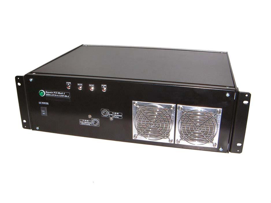
8 Figure 2 BASE MOBILE GND ALARM DL IN BUILDING REPEATER PCS/A ALC DL ALC UL ALARM UL POWER db Gain Adjustment DOWNLINK db Gain Adjustment UPLINK BDA Mechanical Outline Page 8
9 OUTDOOR BDA INSTALLATION PROCEDURE IMPORTANT: DO NOT APPLY A.C. OR DC POWER TO THE BDA UNTIL CABLES ARE CONNECTED TO BOTH PORTS OF THE BDA AND THE ANTENNAS. 1. Mount the BDA on the structure with the RF connectors pointing DOWN. Using appropriate screws and anchors, attach the BDA to the structure using the six mounting holes on the side flanges. 2. Ensure that the isolation between the donor antenna and the service antenna is at least 12 db greater than the BDA gain. (Use the higher of the Uplink and Downlink gains reported on the BDA test data sheet). 3. Connect the cable from the donor antenna to the BDA connector labeled BASE and the cable from the service antennas to the BDA connector labeled MOBILE. 4. Open the access door on the BDA and verify that the Uplink and Downlink ALC switches are in their factory preset ON positions and attenuation is positioned to its maximum setting. 5. Connect the AC power cord to the BDA and then to the power source. Turn the power switch to its ON position. Verify that the Power On indicator is lit. Close the access door. Installation of the BDA is now complete. To adjust the gain controls to suit the specific signal environment, refer to Outdoor BDA Operation. Note: For repeat installations of existing equipment, make sure the attenuation is positioned to its maximum setting (30 db). After verification of the attenuation, follow the above steps starting with step 1. RF EXPOSURE WARNING The antenna used for this transmitter must be fixed-mounted on outdoor permanent structures. In order to satisfy the FCC RF exposure requirements, the BDA/antenna installation must comply with the following: The downlink indoor antenna (Omni type or similar antenna) must be installed so as to provide a minimum separation distance of 0.36 meters (36 cm) between the antenna and persons within the area. (This is calculated with an antenna that has a maximum gain of [5 dbi, VSWR >?> 1.5:1, Zo = 50 ohms, and a cable attenuation of between 2-10 db) The uplink outdoor antenna (Yagi type or similar directional antenna) must be installed so as to provide a minimum separation distance of 0.29 meters (29 cm) between the antenna and persons within the area. (This is calculated with an antenna that has a maximum gain of [15 dbi, VSWR >?> 1.5:1, Zo= 50 ohms, and a cable attenuation of between 2-10 db). Page 9
10 BDA OPERATION Variable Step Attenuator BDA gain can be reduced by up to 30 db in 2 db steps using the variable step attenuator (Figure 3). Gain adjustment is made with rotary switches accessible via the access door on the BDA enclosure. Arrows on the shafts of these switches point to the value of attenuation selected. BDA gain can be determined by subtracting the attenuation value from the gain reported on the BDA Test Data Sheet for that side of the unit. The attenuators are labeled for Uplink and Downlink. ALC (Automatic Level Control) To minimize intermodulation products, the Uplink amplifier and the Downlink amplifier in the BDA contain an ALC feedback loop (Figure 5). The ALC circuit senses the output power and limits it to the factory preset level of +25 dbm on the Uplink and +37 dbm on the Downlink. The ALC function has a red indicator lamp located on Panel adjustment (See Figure 5), the LED s illuminate when output power meets or exceeds the ALC set point. To establish proper operating gain on the Uplink and Downlink sides, start with the Downlink. Observe the red indicator lamp on the Downlink panel. Units are shipping with maximum attenuation. Decrease attenuation one step at a time until the lamp is lit. Then, using the Downlink step attenuator, increase the attenuation until the lamp goes off. Repeat the process for the Uplink. The level indicator is accurate to +/- 0.4 db of the ALC set point. Note: Operation of the BDA in the alarm condition will void the warranty, and output power should be immediately reduced using the variable step attenuator. Operation of RBDA-PCS-1/25W-90-A at maximum gain with greater than -50 dbm average power incident on the MOBILE port or greater than -40 dbm average power incident on the BASE port can cause damage to the BDA. Page 10


11 Figure 3 Variable Gain Adjustment Access Downlink ALC & Alarm LED s Uplink ALC & Alarm LED s Power Switch & Indicator UPLINK DOWNLINK Figure 4 Back Panel AC Line IN BASE & MOBILE Connectors Ground Lug Page 11
12 DIAGNOSTICS GUIDE The BDA provides long term, care-free operation and requires no periodic maintenance. There are no user-serviceable components inside the BDA. This section covers possible problems that may be related to the installation or operating environment. a. Gain Reduction Possible causes: Bad RF cables or RF connections to antennas, damaged antennas. b. Excessive Intermodulation or Spurious Possible causes: Amplifier oscillation caused by insufficient isolation. The isolation between two antennas is given by the equation: Isolation = Log (F x D) Gt Gr Where: F = frequency (GHz) D = separation (Km) Gt = transmit antenna gain (in the direction of the receive antenna). Gr = receive antenna gain (in the direction of the transmit antenna). For example, at the PCS frequencies, the antenna isolation at 100 m separation is about 78 db for omni-directional antennas (0 db gain). To increase isolation, the antennas should have higher directivity and must be pointed away from each other. c. Occasional Drop-out of some Channels Possible causes: One channel with very strong power dominates the RF output of the amplifier. 38 Leuning Street South Hackensack, NJ Tel Fax sales@gwaverf.com Page 12
Installation and Operation Manual for Signal Booster I
 Installation and Operation Manual for Signal Booster I Manual Part Number 7-9470 WARNING: This is NOT a consumer device. It is designed for installation by FCC Licensees and Qualified Installers. You must
User's Manual F10G-5S-LCD 1 / 20 BOOST CELL PHONE SIGNAL BOOSTERS MADE BY HUAPTEC
 User's Manual F10G-5S-LCD 1 / 20 BOOST CELL PHONE SIGNAL BOOSTERS MADE BY HUAPTEC Table of contents WHAT IS INCLUDED... 3 1 HOW IT WORKS... 3 2 TOOL REQUIRED... 3 3 HOW TO INSTALL YOUR NEW CELLULAR BOOSTER...
INSTALLATION and OPERATION INSTRUCTIONS. FOR FiberLink BI-DIRECTIONAL AMPLIFIER WITH DIVERSITY MW-FBDA-800AB-50W-DIV
 INSTALLATION and OPERATION INSTRUCTIONS FOR FiberLink BI-DIRECTIONAL AMPLIFIER WITH DIVERSITY MW-FBDA-800AB-50W-DIV Page 1 of 15 TABLE OF CONTENTS PARA No. PARAGRAPH PAGE No. 1. OVERVIEW 3 2. COMPONENT
800 MHz BIDIRECTIONAL AMPLIFIER Technical manual
 COMPROD COMMUNICATIONS LTD. Customer Instruction Manual Model # BDA-806870 800 MHz BIDIRECTIONAL AMPLIFIER Technical manual 2015, Comprod Communications LTD. 88 Industriel Blvd Boucherville, QC, J4B 2X2
Table of Contents. Mounting Diagram.. Wiring Information.. Setting the STR 1000 as a Repeater or a Transmitter. STR 1000 Frequently Asked Questions..
 STR 1000 Series Repeater Installation Manual (V 3.0) Table of Contents MOUNTING Mounting Diagram.. Page 2 WIRING INFORMATION Wiring Information.. Page 3 Setting the STR 1000 as a Repeater or a Transmitter.
INSTALLATION MANUAL FOR SAL SERIES WIRELESS CLOCKS SPECIFICATIONS
 INSTALLATION MANUAL FOR SAL SERIES WIRELESS CLOCKS SPECIFICATIONS Time base: Quartz Power input: Battery (2 D cell) : Part # SAL-1BS-12R-0 95 135 VAC / 60 Hz: Part # SAL-1BS-12R-1 7 28 VAC / 60 Hz: Part
ORiNOCO AP-4000MR-LR and AP-4900MR-LR Access Points Safety and Regulatory Compliance Information
 IMPORTANT! Visit http://support.proxim.com for the latest safety and regulatory compliance information for this product. ORiNOCO AP-4000MR-LR and AP-4900MR-LR Access Points Safety and Regulatory Compliance
Guide. Installation. Wilson Electronics, Inc. In-Building Wireless Amplifi er. Contents:
 Amplifier Installation Guide In-Building Wireless Amplifi er Contents: Guarantee and Warranty 1 Antenna Options and Accessories 2 Before Getting Started / How It Works 2 Installation Overview 3 Installation
System Requirements: D-Link Systems, Inc.
 System Requirements: Minimum System Requirements: CD-ROM Drive Computers with Windows, Macintosh, or Linux-based operating systems Installed Ether net Adapter Internet Explorer version 6.0 or Netscape
User Warnings MUST READ!
 Abbreviations....2 Safety..2 1. Preface... 3 2. Introduction / Features & Functions..5 3. Installation.7 3.1 Installation Procedure... 8 Terminology BTS CDMA DL GSM iden MS PCS RF UL DL Donor LED Meaning
User Warnings MUST READ!
 Abbreviations....2 Safety..2 1. Preface... 3 2. Introduction / Features & Functions..5 3. Installation.7 3.1 Installation Procedure... 8 Terminology BTS CDMA DL GSM iden MS PCS RF UL DL Donor LED Meaning
User Warnings MUST READ!
 Abbreviations....2 Safety..2 1. Preface... 3 2. Introduction / Features & Functions..5 3. Installation.7 3.1 Installation Procedure... 8 Terminology BTS CDMA DL GSM iden MS PCS RF UL DL Donor LED Meaning
Product Line. Represented by:
 Product Line Represented by: Type of equipment How to read our BDA (or One Way) part number RBDA- 19 Rack BDA FOBDA Fiber Optic BDA RFOBDA Fiber in 19 rack BDA GXXX One Way Booster Band Type (See Frequency
Video Mono Audio Baluns
 FEBRUARY 1998 IC443A Video Mono Audio Baluns Video Mono Audio Balun AUDIO 1 PAIR 1 (4 & 5) VIDEO 1 PAIR 4 (7 & 8) AUDIO 2 PAIR 2 (3 & 6) VIDEO 2 PAIR 3 (1 & 2) CUSTOMER SUPPORT INFORMATION Order toll-free
Technical Manual. Mobile Communication Mini Booster Model: PW-MB or PW-MB10-900
 Technical Manual Mobile Communication Mini Booster Model: PW-MB10-800 or PW-MB10-900 PW-MB10-2100 or PW-MB10-1800 Page 1 Table of Contents Introduction Name & Function How to install the system User Attentions
Dual Band Home Booster
 Dual Band Home Booster DBHB-20 Dual Band Home Booster 800 & 1900 MHz INSTALLATION AND OPERATION MANUAL 5700 9004 055 REV. 1.0 August 2005 Proprietary Information The information contained herein is proprietary
User Manual WHM520V. 1. Introduction. 2. Feature
 User Manual 1 Introduction The module is wireless audio module based on AV5100 The AV5100 is 5GHz wireless audio SoC (System-on-chip), optimized for building point to multi-point digital wireless audio
Copyright Teletronics International, Inc. Patent Pending
 Copyright 2003 By Teletronics International, Inc. Patent Pending FCC NOTICES Electronic Emission Notice: This device complies with Part 15 of the FCC rules. Operation is subject to the following two conditions:
Ambient Level Controller
 Ambient Level Controller Installation and Use Manual Issue 1, October 1999 1999 Bogen Communications, Inc. All rights reserved. 54-2028-01 9910 Model: LUALC PEC Code: 5335-621 COM Code: 408184273 Select
Wireless AC Circuit Identifier
 User's Guide Wireless AC Circuit Identifier Models RT30 and RT30-E 99 Washington Street Melrose, MA 02176 Phone 781-665-1400 Toll Free 1-800-517-8431 Visit us at www.testequipmentdepot.com Back to the
Power Genius XL User Manual rev 10.
 Power Genius X User Manual rev 10. 1/23 Table of Contents 0. Important notice...3 1. Unpacking...5 1.1. Front Panel...5 1.2. Back Panel...6 1.3. BCD/PTP connector pinout...8 2. Using with Radios...9 2.1.
12V Victor 888 User Manual
 The Victor speed controllers are specifically engineered for robotic applications. The high current capacity, low voltage drop, and peak surge capacity make the Victor ideal for drive systems while its
Video Stereo Audio Baluns
 FEBRUARY 1998 IC441A Video Stereo Audio Baluns Video Stereo Audio Balun VIDEO PAIR 4 (7 & 8) AUDIO(L) PAIR 2 (3 & 6) AUDIO(R) PAIR 3 (1 & 2) CUSTOMER SUPPORT INFORMATION Order toll-free in the U.S. 24
PTE-C70 Cell Phone Signal Booster User Manual
 PTE-C70 Cell Phone Signal Booster User Manual 1 / 8 SAFETY WARNINGS W ARNI NG: This equipm ent should be installed and operated w ith m inim um distance 2 0 cm betw een the radiator& your body. FCC Cautions:
Stealth X2 Dual Band Boosters
 Stealth X2 Dual Band Boosters BUILDINGS HOMES COTTAGES Stealth X2 Dual Band Boosters Table of Contents Features...3 Specifications...3 Package contents...4 Optional Parts...4 Antenna and Booster Installation...5
On-Line Cardio Theater Wireless Digital Transmitter Installation and Instruction Manual
 On-Line Cardio Theater Wireless Digital Transmitter Installation and Instruction Manual Full installation instructions accompany your Cardio Theater equipment order. This On-Line version of our Installation/Instruction
Copyright Black Box Corporation. All rights reserved.
 Copyright 2004. Black Box Corporation. All rights reserved. 1000 Park Drive Lawrence, PA 15055-1018 724-746-5500 Fax 724-746-0746 JULY 2004 LW6200A LW6201A Pure Networking 2.4-GHz Antennas CUSTOMER SUPPORT
CCR24T CCR24R. User s Guide WIRELESS TRANSMITTER SYSTEM WARRANTY SERVICE CARD WARRANTY CARD
 WARRANTY SERVICE CARD WARRANTY CARD PRODUCT NAME Wireless Transceiver System PERIOD MODEL NAME CCR24GEN YEAR PURCHASE DATE.. 200_ From the date of WARRANTY PERIOD.. 200_ purchase. CUSTOMER S ADDRESS :
F10I-EGSM Single System
 F10I-EGSM Single System 1 Table of contents How it works... 3 Package contents... 4 Troubleshooting... 14 Specifications... 15 Product Warranty... 16 Safety Warnings... 17 2 How it works Huaptec F10I-EGSM
IS76 Beacon with Ferrite Antenna Installation Manual
 IS76 Beacon with Ferrite Antenna Installation Manual V2 F.01U.278.518 2013.10 Document # F.01U.278.518 V2 IS76 Beacon with Ferrite Antenna: Installation Manual Edition: October 2013 Author: TeleAlarm TeleAlarm
CRUX II/BTGPS USER GUIDE. Model:D1598
 CRUX II/BTGPS USER GUIDE Model:D1598 0 Federal Communication Commission Interference Statement This equipment has been tested and found to comply with the limits for a Class B digital device, pursuant
IS76 Beacon with Ferrite Antenna Installation Manual
 IS76 Beacon with Ferrite Antenna Installation Manual Edition: June 2016 Document N : F.01U.136.807 V3 Page 1 of 10 Document No F.01U.136.807 V3 IS76 Beacon with Ferrite Antenna: Installation Manual Edition:
Radio Micro Force Manual v1.1
 Radio Micro Force Manual v1.1 Preston Cinema Systems 1659 Eleventh Street Santa Monica CA 90404 tel 310-453-1852 fax 310-453-5672 www.prestoncinema.com Table of Contents 1. Description 2. Operation 3.
User Manual LTE 4G 850/2600. Wide Dual Band Repeater REDUTELCO TECHNOLOGY CO.,LTD January
 User Manual LTE 4G 850/2600 Wide Dual Band Repeater REDUTELCO TECHNOLOGY CO.,LTD. 2015 January Information in this manual is subject to change without notice http:www.redutelco.com 2009 Redutelco All rights
REDUTELCO TECHNOLOGY CO.,LTD.
 User Manual Wide Band Repeater REDUTELCO TECHNOLOGY CO.,LTD. 2013 January Information in this manual is subject to change without notice http:www.redutelco.com 2009 Redutelco All rights reserved 1 Table
Low Loss Combiner LLC-1900-IN DATA SHEET. Overview
 DATA SHEET Combines Multiple Technologies onto a Single Feed Line Low Loss Combining Combining for Multiple Technologies (GSM/UMTS, UMTS/UMTS, UMTS/LTE, CDMA/LTE, etc.) Minimal or No Guard Band High Reliability
AD511-2 Active Iridium Antenna User Manual. 1 AD511-2 Active Iridium Antenna User Manual October FEBRUARY 2018 V2.0
 AD511-2 Active Iridium Antenna User Manual 1 AD511-2 Active Iridium Antenna User Manual October 2017 1.0 FEBRUARY 2018 V2.0 TABLE OF CONTENTS 1. FCC APPROVAL... 3 1.1. FCC 15.19 (A) (3)... 3 1.2. FCC 15.105
IMPORTANT: THIS DEVICE MUST BE PROFESSIONALLY INSTALLED READ AND UNDERSTAND ALL INSTRUCTIONS BEFORE BEGINNING INSTALLATION
 INSTALLATI INSTRUCTIS Models: RB-G-K10, RB-TX10 IMPORTANT: THIS DEVICE MUST BE PROFESSIALLY INSTALLED READ AND UNDERSTAND ALL INSTRUCTIS BEFORE BEGINNING INSTALLATI The Miller Edge RBand Monitored Gate
User Warnings MUST READ!
 Abbreviations....2 Safety..2 1. Preface... 3 2. Introduction / Features & Functions..5 3. Installation.7 3.1 Installation Procedure... 8 3.1 Installation Procedure Con t 9 Terminology AGC BTS CDMA db DL
Blue Point Engineering
 Overview Blue Point Instruction Board 2-CH Boards, Terminal Block and Ribbon Cable I Type: RF Radio (315 MHz) 1-2 Channels (FCC Part 15 Compliant Components). Operating Voltage: 6-15 VDC @ 1 Amp (Wall
RM24100D. Introduction. Features. 2.4GHz 100mW RS232 / RS485 / RS422 DSSS Radio Modem (IEEE compliant) Operating Manual English 1.
 Operating Manual English 1.") RM24100D 2.4GHz 100mW RS232 / RS485 / RS422 DSSS Radio Modem (IEEE 802.15.4 compliant) Operating Manual English 1.09 Introduction The RM24100D radio modem acts as a wireless serial cable replacement and
RM24100D 2.4GHz 100mW RS232 / RS485 / RS422 DSSS Radio Modem (IEEE 802.15.4 compliant) Operating Manual English 1.09 Introduction The RM24100D radio modem acts as a wireless serial cable replacement and
Appearance of device and accessories may vary.
 Tri-Band 4G-V Adjustable Gain 700 (Band 13) / 800 / 1900 MHz In-Building Wireless Smart Technology Signal Booster (Band 13 is 700 MHz Verizon LTE) Tri-Band 4G-A Adjustable Gain 700 (Band 12/17) / 800 /
F10-GSM Single System
 F10-GSM Single System 1 Table of content How it works... 3 Package contents... 4 Install your hardware... 5 Troubleshooting... 14 Specifications... 15 Product Warranty... 16 Safety Warnings... 17 2 How
SF C-Series. 900 MHz Wireless Switch Follower/Remote Control Receiver (with On-Board 10-Amp Relays) Typical Applications
 Typical Applications") Long Range Wireless Applications 900 MHz Wireless Switch Follower/Remote Control Receiver (with On-Board 10-Amp Relays) The SF900C Series Remote Control/Switch Followers are a twoway system designed to
Long Range Wireless Applications 900 MHz Wireless Switch Follower/Remote Control Receiver (with On-Board 10-Amp Relays) The SF900C Series Remote Control/Switch Followers are a twoway system designed to
TM14-2.4G/R6014FS/R608FS Radio Control Instruction Manual
 TM14-2.4G/R6014FS/R608FS Radio Control Instruction Manual INTRODUCTION Thank you for purchasing a FutabaR digital proportional R/C system. In order for you to make the best use of your system and to use
Disclaimers. Important Notice
 Disclaimers Disclaimers Important Notice Copyright SolarEdge Inc. All rights reserved. No part of this document may be reproduced, stored in a retrieval system, or transmitted, in any form or by any means,
SolidRF SOHO Tri-Band Cell Phone Signal Booster for GSM, GPRS, CDMA 3G and Verizon 4G LTE. 700 MHz(Band 13) / 850 MHz / 1900 MHz ONLY
 / 850 MHz / 1900 MHz ONLY") SolidRF SOHO Tri-Band Cell Phone Signal Booster for GSM, GPRS, CDMA 3G and Verizon 4G LTE 700 MHz(Band 13) / 850 MHz / 1900 MHz ONLY If you have any questions or concerns when installing or operating your
SolidRF SOHO Tri-Band Cell Phone Signal Booster for GSM, GPRS, CDMA 3G and Verizon 4G LTE 700 MHz(Band 13) / 850 MHz / 1900 MHz ONLY If you have any questions or concerns when installing or operating your
SP GHz Digital Wireless Speakers. User s Manual. Please read before using the equipment. Please visit for details.
 SP1390 2.4GHz Digital Wireless Speakers User s Manual Please read before using the equipment. Please visit www.promowide.com for details. INTRODUCTION This 2.4G digital wireless speakers system uses latest
U S E R S M A N U A L
 U S E R S M A N U A L C2104001 BCM 43224 WiFi Card Contents SECTION ONE: INTRODUCTION... 3 1. INTRODUCTION... 3 1.1 SCOPE... 3 1.2 FUNCTION... 3 1 2 PRODUCT SPECIFICATION... 4 2.1 HARDWARE SPECIFICATION...
TABLE OF CONTENTS APPENDIX A... 8 APPENDIX B... 9 APPENDIX C... 12
 Version 1.3 July 2002 TABLE OF CONTENTS 1.0 DESCRIPTION... 1 2.0 AMPLIFIER FEATURES... 1 3.0 DEVICE SPECIFICATIONS... 2 4.0 INDOOR AMPLIFIER KIT... 3 5.0 INSTALLATION AND CABLING INSTRUCTIONS... 4 6.0
REDUTELCO TECHNOLOGY CO.,LTD.
 User Manual Wide Tri Band Booster (23dBm) REDUTELCO TECHNOLOGY CO.,LTD. 2013 January Information in this manual is subject to change without notice http:www.redutelco.com 2009 Redutelco All rights reserved
English KS-DR3005D POWER AMPLIFIER: INSTRUCTION MANUAL
 KS-DR005D POWER AMPLIFIER: INSTRUCTION MANUAL B5E-009-00/00 [W] WARNING If the fuse blows, first make sure the wires aren t touching to cause a short circuit then replace the old fuse with one with the
Guide. Installation. Wilson Electronics, Inc. In-Building Wireless Amplifi er. Contents:
 Amplifier Installation Guide In-Building Wireless Amplifi er Contents: Guarantee and Warranty 1 Antenna Options and Accessories 2 Before Getting Started / How It Works 3 Installation Overview 4 Installing
900 MHz Digital Wireless Indoor/Outdoor Speakers
 4015007 900 MHz Digital Wireless Indoor/Outdoor Speakers User s Manual This 900 MHz digital hybrid wireless speaker system uses the latest wireless technology that enables you to enjoy music and TV sound
Mini Hi-Fi Audio *MFL * SIMPLE MANUAL
 ENGLISH SIMPLE MANUAL Mini Hi-Fi Audio To view the instructions of advanced features, visit http://www.lg.com and then download Owner s Manual. Some of the content in this manual may differ from your unit.
IMPORTANT: THIS DEVICE MUST BE PROFESSIONALLY INSTALLED. READ AND UNDERSTAND ALL INSTRUCTIONS BEFORE BEGINNING INSTALLATION.
 INSTALLATI INSTRUCTIS Model: RB-G-K10 IMPORTANT: THIS DEVICE MUST BE PROFESSIALLY INSTALLED. READ AND UNDERSTAND ALL INSTRUCTIS BEFORE BEGINNING INSTALLATI. The Miller Edge RBand Monitored Gate Edge Transmitter/Receiver
Instruction Manual. for Media Monkey. 1
 TM TM Instruction Manual for Media Monkey www.audioaperemote.com 1 Congratulations on acquiring your fine Audio Ape product Let s dive right in, getting up and running is a snap. Here are the components:
Table of Contents. Wall Mount Installation Page 2 Double Mount Installation Page 3. Wiring Information... Page 4. Operational Instructions Pages 5-8
 MOUNTING Table of Contents Wall Mount Installation Page 2 Double Mount Installation Page 3 WIRING INFORMATION Wiring Information... Page 4 OPERATION Operational Instructions Pages 5-8 FREQUENTLY ASKED
RM24100A. *Maximum transmit power output levels and local radio frequency regulator bodies must be obeyed in the country of operation.
 RM24100A 2.4GHz 100mW RS232 / RS485 / RS422 DSSS Radio Modem (IEEE 802.15.4 compliant) Operating Manual English 1.02 Introduction The RM24100A radio modem acts as a wireless serial cable replacement and
MPRF01 Wireless 5uA Inductive Proximity Sensor RF System
 System Description; The MPRF01 is a simple ready to use Wireless Inductive. No programming is required; just insert 2, (1.5V) AA batteries into the Transmitter module. The RF receiver module is connected
Do not expose this device to water or moisture of any kind. Do not mix new and old batteries or batteries of different types.
 1 SAFETY WARNINGS AND GUIDELINES This device is intended for indoor use only. Do not expose this device to water or moisture of any kind. Do not mix new and old batteries or batteries of different types.
Ditch Witch 750 Tracker Specs Provided by FOREWORD
 750/752 Display - FOREWORD 1 Ditch Witch 750 Tracker Specs Provided by www.aaatesters.com FOREWORD This manual is an important part of your equipment. It provides safety information and operation instructions
Black Oak / Light Oak / Cherrywood Wireless Panel Speaker
 4015115/4015116/4015117 Black Oak / Light Oak / Cherrywood Wireless Panel Speaker With Infrared Remote Control USER GUIDE For use with: Introduction These 900 MHz stereo wireless speaker system uses the
Cellular (850 Band) DAS. Tray with Independent Control. General Information. Key Features: Tel: Fax:
 DAS. Tray with Independent Control. General Information. Key Features: Tel: Fax:") Cellular (850 Band) DAS Interface Tray with Independent Control Tel: 201-342-3338 www.cciproducts.com General Information CCI s Cellular Band DAS Interface Tray with Independent Control provides an integrated,
Cellular (850 Band) DAS Interface Tray with Independent Control Tel: 201-342-3338 www.cciproducts.com General Information CCI s Cellular Band DAS Interface Tray with Independent Control provides an integrated,
GX_W60_V3.5 WIFI Video module Mnaual
 GX_W60_V3.5 WIFI Video module Mnaual W60 Tel:86-755-26066032 Fax:26002892 Web site:www.netopsun.com 1 / 8 1 summary 1.1 overview of the whole W60_WIFI module is the latest introduction of crown Asahi Technology
900 MHz. Frequency Hopping RS-485 Master/Slave auto-sensing radio interface.
 MDR210A-485 900 MHz. Frequency Hopping RS-485 Master/Slave auto-sensing radio interface. Black Box Corporation Lawrence, PA - http://www.blackbox.com - Ph 877-877-BBOX - Fax 724-746-0746 Table of Contents
Driveway Alarm INSTALLATION MANUAL
 WIRELESS ACCESS CONTROLS Driveway Alarm INSTALLATION MANUAL Mounting post Transmitter Receiver Transformer Sensor Kit Includes: Transmitter Module Sensor Receiver Transformer Mounting post (3 pieces) Installation
A01-eNETL2TUV_Manual_RevH.doc. GE MDS enetl2t/u/v Manual P/N A01 Rev H
 GE MDS enetl2t/u/v Manual P/N 05-4186A01 Rev H 05-4186A01 Rev H Page 1 of 7 12/19/2016 Table of Contents 1 Important Information... 3 1.1 RF Exposure... 3 1.2 FCC Approval Notice... 3 1.3 FCC Part 80 Information...
ScreenLogic Wireless Connection Kit. Installation Guide. pool/spa control system
 pool/spa control system ScreenLogic Wireless Connection Kit Installation Guide P/N 520663 - Rev A 8 Technical Support Contact Technical Support at: Sanford, North Carolina (8 A.M. to 5 P.M.) Phone: (800)
850 MHz Antenna Sharing Combiner ASC850VG12A
 DATA SHEET Small, lightweight, outdoor unit Dual Technology Combiner (GSM 850 / UMTS 850) Can also be used for same technology (e.g. GSM/GSM) Can be used close to Antenna Can be used in Ground Based Applications
Innovation First, Inc. RS MHz Robot Controller User Manual
 RS-422 900 MHz Robot Controller User Manual 10.31.2006 www.innovationfirst.com Page 2 Table of Contents 1. Robot Controller Overview... 3 2. Installation... 3 3. Theory of Operation... 3 4. FCC / Industry
User Manual. Product Name:tablet Model Name:TM800A740M Brand Name:NuVision. Manufacture:Shenzhen Vastking Electronic Co.,LTD.
 User Manual Product Name:tablet Model Name:TM800A740M Brand Name:NuVision Manufacture:Shenzhen Vastking Electronic Co.,LTD. FCC Warning This device complies with part 15 of the FCC
Blue Point Engineering Inc.
 Engineering Inc. ireless Radio Control of Puppets Setup Overview RF Control C Pointing the ay to Solutions! Hardware Setup Overview Page 1 Servo No.1 Servo No.2 Control Signal Line RX8ch1,2 Servo Board
Users Manual AgCam /EnduraCam TM
 Users Manual AgCam /EnduraCam TM 2.4GHz Analog Wireless A/V Sender Part Number: RHPAIR RHTX & RHWPTX RHRX & RHES Contents: 1. Components... 2 1.1 Standard Kit... 2 1.2 Waterproof Transmitter... 3 1.3 Easy
Hi-Fi Shelf System *MFL * SIMPLE MANUAL
 ENGLISH SIMPLE MANUAL Hi-Fi Shelf System Please read this manual carefully before operating your set and retain it for future reference. To view the instructions of advanced features, visit http://www.lg.com
Mini Hi-Fi Audio *MFL * SIMPLE MANUAL
 ENGLISH SIMPLE MANUAL Mini Hi-Fi Audio To view the instructions of advanced features, visit http://www.lg.com and then download Owner s Manual. Some of the content in this manual may differ from your unit.
INSTRUCTION MANUAL LCS TX
 INSTRUCTION MANUAL LCS TX 4 Channel Transmitter LCS1 Single Channel Transmitter Cardio Theater Inc Service 1-800-776-6695 Sales 1-800-CARDIO-1 1 Introduction CONGRATULATIONS on your choice of this product
Wilson. iden 800 MHz. Adjustable Gain In-Building Wireless Smart Technology Signal Booster. Appearance of device and accessories may vary.
 iden 800 MHz Adjustable Gain In-Building Wireless Smart Technology Contents: Options & Accessories....................... 1 Quick Install Overview............................... 2 Installation Diagram.................................
Blue Point Engineering Inc.
 nc. Wireless Radio Control of Puppets Setup Overview RF Control C Hardware Setup Overview Servo No.1 Servo No.2 Control Signal Line RX8-ch1,2 Servo Board WZ-12 RX8-ch3,4 Servo Board WZ-12 Power Line DC
802.11n, 2.4G 1T1R Wireless LAN PCI Express Half Mini Card
 802.11n, 2.4G 1T1R Wireless LAN PCI Express Half Mini Card WN6605LH Realtek RTL8191SE User s Manual Ben J. Chen 3/4/2010 Federal Communication Commission Interference Statement This equipment has been
Focus Iris Manual Ver 1.1
 Focus Iris Manual Ver 1.1 Preston Cinema Systems 1659 Eleventh Street Santa Monica CA 90404 tel 310 453 1852 fax 310 453 5672 www.prestoncinema.com Table of Contents 1. Description 2. Operation 3. Specifications
Remote Control Outlets Operating Instructions
 Remote Control Outlets Operating Instructions - FOR INDOOR OR OUTDOOR USE - IMPORTANT SAFEGUARDS Signal Word Definitions NOTE: These are general definitions only; all may not pertain to the actual product
REDUTELCO TECHNOLOGY CO.,LTD.
 Penta Band Booster (27dBm) REDUTELCO TECHNOLOGY CO.,LTD. 2018 January Information in this manual is subject to change without notice http:www.redutelco.com 2009 Redutelco All rights reserved 1 Table of
USER MANUAL Digital Wireless Gateway U9120-W4 (P/N: 44002G-01)
") USER MANUAL Digital Wireless Gateway U9120-W4 (P/N: 44002G-01) 19549P-82 (11-16) 2016 DAVID CLARK COMPANY INCORPORATED Cautions and Warnings READ AND SAVE THESE INSTRUCTIONS. Follow the instructions in
USER MANUAL Digital Wireless Gateway U9120-W4 (P/N: 44002G-01) 19549P-82 (11-16) 2016 DAVID CLARK COMPANY INCORPORATED Cautions and Warnings READ AND SAVE THESE INSTRUCTIONS. Follow the instructions in
User Warnings MUST READ!
 Abbreviations....2 Safety..2 1. Preface... 3 2. Introduction / Features & Functions..5 3. Installation.7 3.1 Installation Procedure... 8 3.1 Installation Procedure Con t 9 Terminology AGC BTS CDMA db DL
Active Transmitter Combiner 8:1 AC 3200-II. Instruction manual
 Active Transmitter Combiner 8:1 AC 3200-II Instruction manual Contents Contents Important safety instructions... 2 The AC 3200-II active transmitter combiner 8:1... 4 Delivery includes... 4 Connection
10~30dBm Series Repeater SYN-30L-S With LCD Touch Screen User Manual
 10~30dBm Series Repeater SYN-30L-S With LCD Touch Screen User Manual CONTENT PREFACE... 3 1. SAFETY WARNINGS... 3 2. INTRODUCTION... 3 3. SYSTEM CHARACTERISTICS... 5 3.1. FEATURES... 5 3.2. APPEARANCE
WML- 46### User Manual
 Page 1 of 6 WML- 46### User Manual The purpose of this manual is to explain correct way how to integrate module WML- 46### to the end product. It includes procedures that shall assist you to avoid unforeseen
Contact Tech Support at or at Safety and Warnings
 ! Safety and Warnings Turn AC power OFF at the mains before working on any electrical connections. All AC power wiring and coaxial cable wiring must conform to local or national codes. The AC line voltage
RQT-xxx-RCVR Owner s Manual Quick Talk TM Wireless Voice Monitor & Alarm transmitter with factory installed MHz Keyfob Receiver
 RQT-xxx-RCVR Owner s Manual Quick Talk TM Wireless Voice Monitor & Alarm transmitter with factory installed 433.92 MHz Keyfob Receiver RQT-151-RCVR RQT-151M-RCVR RQT-451-RCVR RQT-152-RCVR RQT-152M-RCVR
Quick Start Guide. Antenna Alignment Tool AIMWLLR0-35. QSG rev 7 AIMWLLR0-35 [NRB-0200] QSG.indd 1
![Quick Start Guide. Antenna Alignment Tool AIMWLLR0-35. QSG rev 7 AIMWLLR0-35 [NRB-0200] QSG.indd 1](/thumbs/86/94268876.jpg "Quick Start Guide. Antenna Alignment Tool AIMWLLR0-35. QSG rev 7 AIMWLLR0-35 [NRB-0200] QSG.indd 1") Quick Start Guide Antenna Alignment Tool AIMWLLR0-35 QSG-00097 rev 7 AIMWLLR0-35 [NRB-0200] QSG.indd 1 Welcome This quick start guide is designed to familiarize you with the features and use of the NetComm
Quick Start Guide Antenna Alignment Tool AIMWLLR0-35 QSG-00097 rev 7 AIMWLLR0-35 [NRB-0200] QSG.indd 1 Welcome This quick start guide is designed to familiarize you with the features and use of the NetComm
User Manual. User Manual. Tri-Band Repeater February. -- Tri-Band Repeater (Model: RP33EDW) (900/1800/2100)
 (900/1800/2100)") Tri-Band Repeater (900/1800/2100) User Manual 2015 February Information in this manual is subject to change without notice http:www.redutelco.com 2009 Redutelco All rights reserved 1 Table of Contents
Tri-Band Repeater (900/1800/2100) User Manual 2015 February Information in this manual is subject to change without notice http:www.redutelco.com 2009 Redutelco All rights reserved 1 Table of Contents
User's Guide. Wireless AC Circuit Identifier. Models RT30 and RT32
 User's Guide Wireless AC Circuit Identifier Models RT30 and RT32 Introduction Congratulations on your purchase of Extech s Model RT30 (914Mhz) or RT32 (869MHz) Wireless AC Circuit Identifier. The detector
Manual Unihan UPWL6580
 Manual Unihan UPWL6580 Federal Communications Commission Statement This device complies with FCC Rules Part 15. Operation is subject to the following i. This device may not cause harmful interference,
IQ TM Spread Spectrum (SS) Radio
 Radio") IQ TM Spread Spectrum (SS) Radio Installation Guide for the IQ TM Central Control System 638174-02 Rev A (IQ SS-Radio install guide (EN)) source.indd 1 12/17/2010 11:39:14 AM Symbols NOTE: Symbol alerts
IQ TM Spread Spectrum (SS) Radio Installation Guide for the IQ TM Central Control System 638174-02 Rev A (IQ SS-Radio install guide (EN)) source.indd 1 12/17/2010 11:39:14 AM Symbols NOTE: Symbol alerts
Datasheet. Bluetooth Smart Module. Pacwave Bluetooth Smart (BLE) Module DESCRIPTION FEATURES
 Module DESCRIPTION FEATURES") Pacwave Bluetooth Smart (BLE) Module FEATURES Built in CSR μenergy CSR1010 Bluetooth Smart (v4.1) chipset +7.5dBm Maximum RF Transmit Output Power 92.5dBm RF Receive Sensitivity RSSI Monitoring Built in
Pacwave Bluetooth Smart (BLE) Module FEATURES Built in CSR μenergy CSR1010 Bluetooth Smart (v4.1) chipset +7.5dBm Maximum RF Transmit Output Power 92.5dBm RF Receive Sensitivity RSSI Monitoring Built in
Trace Elliot Elf Bass Instrument Amplifier
 Trace Elliot Elf Bass Instrument Amplifier Owner s Manual FCC Compliancy Statement This device complies with Part 15 of the FCC rules. Operation is subject to the following two conditions: (1) this device
Model 1791 VHF Radio User's Manual
 Model 79 VHF Radio User's Manual ALL WEATHER INC 65 NATIONAL DRIVE SACRAMENTO, CA 95834 WWW.ALWEATHERINC.COM 79 VHF RADIO USER'S MANUAL CONTENTS INTRODUCTION... Description... Transmitter Module... Power
EU Series Consumer Mobile Signal Booster Single Band (GSM/DCS/WCDMA/LTE800/LTE1800/LTE2600) Dual Band (ED/EW/DW/L800/L2600)
 Dual Band (ED/EW/DW/L800/L2600)") EU Series Consumer Mobile Signal Booster Single Band (GSM/DCS/WCDMA/LTE800/LTE1800/LTE2600) Dual Band (ED/EW/DW/L800/L2600) 1 Table of content Preface... 3 Safety Warnings... 3 Overview... 4 Package contents...
EU Series Consumer Mobile Signal Booster Single Band (GSM/DCS/WCDMA/LTE800/LTE1800/LTE2600) Dual Band (ED/EW/DW/L800/L2600) 1 Table of content Preface... 3 Safety Warnings... 3 Overview... 4 Package contents...
Technical User Manual JDIR / 40-90
 Technical User Manual JDIR-37-87 / 40-90 Band Selective Industrial Repeater JDTECK INC. 215 Celebration Place, Suite 180-190 Kissimmee FL 34747 Abbreviations....2 Safety..2 1. Preface... 3 2. Introduction