Application Note. StarMIMO. RX Diversity and MIMO OTA Test Range
|
|
|
- Opal Stephens
- 5 years ago
- Views:
Transcription


1 Application Note StarMIMO RX Diversity and MIMO OTA Test Range
2 Contents Introduction P. 03 StarMIMO setup P. 04 1/ Multi-probe technology P. 05 Cluster vs Multiple Cluster setups Volume vs Number of probes 2/ Spatial channel emulator P. 07 Channel Models MIMO OTA testing Channel Models 3/ Radio communication tester P. 08 4/ Amplification unit P. 08 Calibration P. 09 1/ Calibration - Part 1 P. 10 2/ Calibration - Part 2 P. 10 SAM MIMO Control software interface P. 11 SAM MIMO Configuration P. 11 Conclusion P. 12 2
3 Introduction In Multiple Input Multiple Output (MIMO) systems, spatial correlation plays an important role. The level of correlation cannot be determined based on antenna characteristics without knowing the propagation characteristics. Therefore, a new Over-the-air (OTA) testing methodology is needed in order to take into account both antenna and propagation characteristics in the system setup when testing multiantenna devices. MIMO-OTA device testing with anechoic chambers emulates complex spatialtemporal propagation environments at the device location in a realistic and repeatable way by using a radio channel emulator connected to a circular array of probes (multiple cluster) or to an array of probes on one side of the chamber forming a single spatial cluster model. Both configurations are referred to as the Multi-probe technique. This technique addresses the need to generate precise spatial channel models at the device location for the evaluation of MIMO antenna and handset performance. Wide band cellular propogation channels exhibit the cluster behavior which can be taken into account by emulating the Spatial Channel model within the anechoic chamber. The clusters are then simultaneously mapped to the probes so that the sum of the transmitted signals at the DUT location is as defined in the model. These measurementbased channel models include all dimensions of the radio channel (time, frequency, space and polarization). Each cluster is split between several probes to enable angular spread. As a result the geometry based environment of the channel model is accurately reproduced within the anechoic chamber. The primary goal of the MIMO OTA measurement system is to be able to compare Multi-antenna/MIMO devices and algorithms based on their throughput performances when tested against spatial channel models. All critical parts of the mobile terminal design (antennas, RF front-end, baseband processing) are tested in an end-to-end configuration. This document aims to present all the most relevant technical features of the MVG StarMIMO system relative to the MIMO OTA measurement technique with anechoic chambers. 3
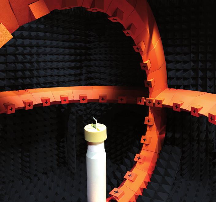
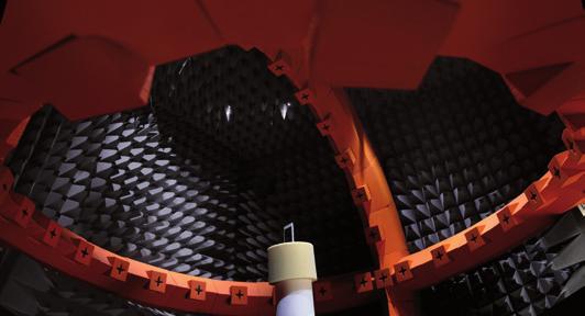
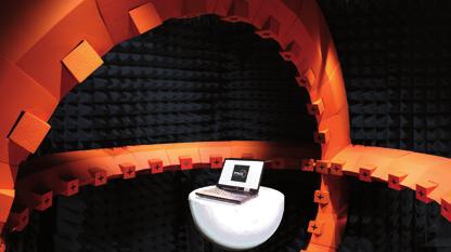
4 StarMIMO setup The StarMIMO main hardware components are highlighted in Figure 1: Data Acquisition & Processing PC Radio Communication Tester Spatial Channel Emulator MIMO Amplification Unit MV-Cal TM Calibration Unit Motion Controller Figure 1. StarMIMO setup In a MIMO OTA setup, signals come simultaneously from different directions around the device. This characteristic setup, combined with a channel emulator, enables the emulation of spatial-temporal propagation environments at the Device under Test (DUT) location. 4

 Figure 2.")
5 Multi-probe technology N number of transmitting antennas (probes) are connected to the spatial channel emulator(s) in order to emulate a complex multipath environment at the DUT location. Figure 2 shows the StarMIMO H setup: SINGLE CLUSTER vs MULTIPLE CLUSTER SETUPS As previously introduced, the probe locations play an important role for the MIMO OTA test range. Probes can be located on a single sector or on a full circle, namely single cluster and multiple cluster approaches respectively. Figure 4, and 5 show a single cluster setup with 4 dual polarized probes and a multiple cluster setup with 8 dual polarized probes respectively. Reference position (0 deg) Figure 2. StarMIMO H test range The probes are dual polarized and there is access to both polarizations at the same time. The frequency bands of the probes are from 400 MHz up to 6 GHz. Figure 4. Single cluster Probe locations The design of the probe is shown in Figure 3: Figure 3. Probe from 400 MHz to 6 GHz Reference position (0 deg) Main parameters of the probe are specified in Table 1: PROBES REF: DP Frequency Bands 400 MHz - 6 GHz Return Loss < 11dB Gain -10 dbi +2 dbi Cross Polarization Coupling* < -35 db to -40 db Table 1. Main parameters of the probe. *Probe is calibrated and anechoic environment is optimized. Figure 5. Multiple Cluster- Probe locations Details about the channel models used for each of the above implementations are shown in the following chapters. It can be considered that the complexity of the setup is reduced with the single cluster. 5

6 TEST VOLUME vs NUMBER OF PROBES The number of probes plays an important role when understanding the test volume and hence the quiet zone of the test range. The test volume is limited by the number of probes for multiple cluster setup and the size of the sector for the single cluster setup. Consequently, a high number of probes extend the ideal performance. This is demonstrated by the plot of correlation coefficient vs. distance between antennas in wavelength at 2 GHz in Figure 7: 8 PROBES For a full circle implementation (multiple clusters) with uniformly separated probes, the general rule the more probes, the larger the test volume is valid since the whole angular domain is sampled. Figure 6 shows the DUT size vs. frequency for a uniform channel with respect to the number of probes used in a multiple cluster setup (full circle): 16 PROBES Figure 6. Max DUT size vs Frequency and number of probes for a uniform distribution of probes (multiple clusters) and uniform channel model Figure 7. Correlation Coefficient for a uniform distribution of probes (multiple cluster); Uniform channel model 8 probes vs 16 probes test range Test volume is approximately 0.8l to 2.2l for the 8 probes and 16 probes cases, respectively. The single cluster setup is a special case with a limited angular coverage of the full angular domain and therefore there is no general rule for the relation between the test volume and the number of probes. There is a big impact on the channel model as the large angular spread requires the OTA probes to be located in a 6

7 wider sector than the small angular spread. This method will better sample the Laplacian shaped cluster power angular spectrum. For example, in the case of +/-45 and +/-55 sectors the Laplacian function of 35 angular spread is better sampled using the sector of +/-55. Figure 8 below (Laplacian PAS with 35 degree angular spread) shows that 1/6 of the power is located > 45 degree and < -45 degree angles. Spatial channel emulator A test signal from a radio communication tester, goes through a spatial channel emulator which emulates the radio channel according to a pre-defined channel model. The most typically emulated parameters are path loss, multipath fading, delay spread, Doppler spread, polarization and of course spatial parameters such as Angle of Arrival (AoA), and Angular Spreads (AS). CHANNEL MODELS The channel models used for MIMO OTA testing are Geometry-based Stochastic Channel Models (GSCM) in which the radio channels are defined by: Transmit Antenna location and pattern Propagation Characteristics (delay, Doppler, AoA, Angular Spread at the transmitter (ASD), Angular Spread at the receiver (ASA), and polarization) Mobile velocity and direction of travel Receiver antenna location and pattern A number of large scale parameters Figure 8. Power Angular Spectrum with 35 angular spread The larger the test volume, the more accurate the tails of the Power Distribution Function (PDF) have to be modeled. Table 2 reports some simulated figures of the Test Volume vs Number of probes when using Spatial Channel Model Extended (SCME) Urban Micro and Urban Macro channel models for both single cluster and multiple cluster setups: TEST UNIFORM PROBES SETUP VOLUME (MULTIPLE CLUSTER) 0.75l l l 32 TEST SECTOR (+/-45 ) PROBES SETUP VOLUME (SINGLE CLUSTER) 0.75l l l 8 TEST SECTOR (+/-55 ) PROBES SETUP VOLUME (SINGLE CLUSTER) 0.75l l l 8 Table 2. Test Volume Vs Number of probes when using SCME Urban Micro and Macro channel models These are measurement-based channel models that have all the dimensions in, space, time, polarization, and frequency. Space and polarization are crucial parameters for determining the spatial correlation. The GSCM family includes the 3 rd Generation Partnership Project (3GPP) standardized channel model, SCME, Winner II, Union Internationale des Telecommunication (ITU), and International Mobile Telecommunications (IMT) Advanced channel models. MIMO OTA TESTING CHANNEL MODELS In the StarMIMO setup, the clusters are simultaneously mapped to the probes so that the sum of the transmitted signals in the center of the array is as defined in the propagation model. The mapping is done in the spatial channel emulator. In this case, the geometry based environment of the channel model is transferred to the anechoic chamber. The most common channel emulators have a specific tool for generating the impulse response of each probe based on the number and location of the probes. 3GPP and the international association for the wireless telecommunication industry (CTIA) have agreed on a set of channel models to be used for the MIMO OTA testing: SCME Urban Micro-cell SCME Urban Macro-cell 7
8 3GPP TR is the reference document for more details about the channel model parameters. Table 3 reports the parameters of the SCME Urban Micro-cell for the multiple cluster case: SCME Urban micro-cell CLUSTER # DELAY [NS] POWER [DB] AOD [ ] AOA [ ] Delay spread [ns] 294 Cluster AS AoD / AS AoA [ ] 5 / 35 Cluster PAS shape Laplacian Total AS AoD / AS AoA [ ] 18.2 / 67.8 Mobile speed [km/h] / Direction of travel [ ] 3,30 / 120 XPR - NOTE: V & H components based on assumed BS antennas 9 db Mid-paths Share Cluster parameter values for: AoD, AoA, AS, XPR Table 3. SCME Urban Micro-cell channel model In the defined single cluster case, all AoA are assumed to be set to 0. Hence, the model has just one cluster in the spatial domain. In terms of the delay positions, the single cluster is the same as the multiple cluster. Other parameters such as Cross Power Ratio (XPR), direction of travel, and mobile velocity are also the same for both implementations. One option in the single cluster is related to the AS AoA, which can be set to 35 or 25 in order to enable a range of spatial correlations based on the type of the DUT. Radio communication tester The radio communication tester generates the wireless signals that are sent to the spatial channel emulator. In 2x2 MIMO OTA testing, two radio frequency (RF) outputs will be used while in Single-input Mulitple Output (SIMO) (RX diversity) testing, only one RF output is connected to the spatial channel emulator. The RF IN/OUT port is connected to the link antenna in order to keep the data connection and be able to measure the Block Error Rate (BLER) and hence the throughput for a given power at the DUT location. Amplification unit In order to increase the total power at the DUT location, each output of the spatial channel emulator is amplified before being sent to the DUT via the probe. A power level of - 50 dbm/15 KHz can be emulated at the DUT location when a channel model is simulated by the channel emulator. This power level is enough for testing LTE protocol at high modulation coding scheme (MCS) such as 64 QAM, and full bandwidth (BW) allocation. One amplification unit is composed of 8 channels/amplifiers. 8

9 Calibration The goal of the calibration process is to ensure equal responses from each output/path, both amplitude and phase, by correcting the errors caused by the setup, such as probe misplacement and differences in gain and phase caused by cables. Figure 9 shows the calibration setup: Data acquisition & processing PC SEVERAL PATHS S21 VNA Spatial Channel Emulator MIMO Amplification Unit MV-Cal TM Calibration Unit Figure 9. Calibration setup The total path loss is measured for each path (channel) from the input of the spatial channel emulator to the DUT location. The calibration is performed by using a static channel model, so called 1 tap model. Both the V and H components of the transmitted signal are calibrated. Usually a reference antenna with known gain characteristics is used, sleeve and loop dipoles are the main choice respectively for V and H components. Gain and phase compensation are then stored on the spatial channel emulator for each channel. All the active components in the test range circuitry are also calibrated by using this process. The calibration process is time consuming mainly due to the following drawbacks: 1. Dipoles are narrow band. 2. Dipoles are single polarized. 3. Active component circuitry, such as amplifiers, mixers, oscillators, etc. are temperature dependent making calibration necessary several times per week and before starting any testing campaign. 4. The probe array is not calibrated. The radioelectric axis of each probe should still be calibrated for high quality testing. All the above can be mitigated by splitting the calibration procedure in two parts and using the MVG patented MV-Cal calibration solution. 9
10 CALIBRATION - PART 1 All the active components in the setup are calibrated. MV-Cal closes the loop and measures the path loss on each channel. Gain and phase compensation are stored in the MV-Cal unit. The whole process takes only a few seconds. Figure 10 shows the components which are calibrated in part 1 of the calibration process: CALIBRATION - PART 2 This part of the calibration concerns only the probe array. The procedure is the same as for a SISO system in which calibration is performed approximately once a year and is usually part of a maintenance contract. VNA Spatial Channel Emulator MIMO Amplification Unit MV-Cal TM Calibration Unit Figure 10. Calibration Part 1 10
, the Base Station Emulator, and Network Analyzer 2. Automatize the gain calibration process, part 1 of the calibration by controlling the MV-Cal unit 3.")


11 SAM MIMO Control software interface The StarMIMO setup, the components and third party equipment are all managed by the control software. The main tasks are: 1. Control the Spatial Channel Emulator(s), the Base Station Emulator, and Network Analyzer 2. Automatize the gain calibration process, part 1 of the calibration by controlling the MV-Cal unit 3. Upload the standardized channel models, i.e. SCME Urban Micro, SCME Urban Macro, and Winner II 4. Data acquisition and plotting of the Throughput vs. Power curve SAM MIMO CONFIGURATION The SAM-MIMO configuration interface will guide you through all the steps necessary to configure the used HW connected to the StarMIMO test range easily. Figure 12 shows the SAM MIMO configuration wizard: This control software is needed for a MIMO OTA test range turnkey solution. Figure 11 shows a screenshot of the software interface: Figure 12. SAMMIMO Configuration Interface Calibration coefficients can be uploaded by using the SAM MIMO configuration interface. Figure 11. SAM MIMO GUI Figure 13 shows how it is done: Figure 13. Uploading calibration coefficients In Figure 13, there are two sets of coefficients for the calibration that are independently uploaded on the SAM MIMO configuration as documented in the earlier section of Calibration. 11

12 Conclusion MIMO is all about correlation. Correlation has a major impact on the throughput performance of a multi-antenna wireless device. Since correlation is both a function of antenna characteristics and propagation channel, MIMO OTA testing enables direct measurement of the true terminal performances. AUTHORS Alessandro Scannavini, MVG Nicolas Gross, MVG The StarMIMO setup is capable of emulating any spatialtemporal characteristics environment at the device under test (DUT) location by utilizing MVG s multi-probe technology with a spatial channel emulator. This is implemented by placing the probes at different location and emulating the MIMO channel with the spatial channel emulator. In a single measurement, it is possible to characterize the performance of the device at the system level, including baseband, RF front-end, and antennas by measuring the throughput in downlink. StarMIMO provides an efficient end-to-end testing of MIMO devices and is a major asset in the design cycle and product validation of mobile devices. For more information about StarMIMO, please visit our site: Or us: sales@microwavevision.com Graphic design: pictures: all rights reserved
Keysight Technologies Theory, Techniques and Validation of Over-the-Air Test Methods
 Keysight Technologies Theory, Techniques and Validation of Over-the-Air Test Methods For Evaluating the Performance of MIMO User Equipment Application Note Abstract Several over-the-air (OTA) test methods
Effectiveness of a Fading Emulator in Evaluating the Performance of MIMO Systems by Comparison with a Propagation Test
 Effectiveness of a Fading in Evaluating the Performance of MIMO Systems by Comparison with a Propagation Test A. Yamamoto *, T. Sakata *, T. Hayashi *, K. Ogawa *, J. Ø. Nielsen #, G. F. Pedersen #, J.
Introduction to MIMO OTA Environment Simulation, Calibration, Validation, and Measurement Results
 Introduction to MIMO OTA Environment Simulation, Calibration, Validation, and Measurement Results Dr. Michael D. Foegelle Director of Technology Development Garth D Abreu Director of RF Engineering Outline
WiMAX Summit Testing Requirements for Successful WiMAX Deployments. Fanny Mlinarsky. 28-Feb-07
 WiMAX Summit 2007 Testing Requirements for Successful WiMAX Deployments Fanny Mlinarsky 28-Feb-07 Municipal Multipath Environment www.octoscope.com 2 WiMAX IP-Based Architecture * * Commercial off-the-shelf
3GPP TR V ( )
") TR 37.976 V11.0.0 (2012-03) Technical Report 3rd Generation Partnership Project; Technical Specification Group Radio Access Network; Measurement of radiated performance for Multiple Input Multiple Output
TR 37.976 V11.0.0 (2012-03) Technical Report 3rd Generation Partnership Project; Technical Specification Group Radio Access Network; Measurement of radiated performance for Multiple Input Multiple Output
Transforming MIMO Test
 Transforming MIMO Test MIMO channel modeling and emulation test challenges Presented by: Kevin Bertlin PXB Product Engineer Page 1 Outline Wireless Technologies Review Multipath Fading and Antenna Diversity
Channel Modelling ETIN10. Directional channel models and Channel sounding
 Channel Modelling ETIN10 Lecture no: 7 Directional channel models and Channel sounding Ghassan Dahman / Fredrik Tufvesson Department of Electrical and Information Technology Lund University, Sweden 2014-02-17
ETSI TR V ( )
") TR 137 976 V12.0.0 (2014-10) TECHNICAL REPORT Universal Mobile Telecommunications System (UMTS); LTE; Measurement of radiated performance for Multiple Input Multiple Output (MIMO) and multi-antenna reception
TR 137 976 V12.0.0 (2014-10) TECHNICAL REPORT Universal Mobile Telecommunications System (UMTS); LTE; Measurement of radiated performance for Multiple Input Multiple Output (MIMO) and multi-antenna reception
Handset MIMO antenna measurement using a Spatial Fading Emulator
 Handset MIMO antenna measurement using a Spatial Fading Emulator Atsushi Yamamoto Panasonic Corporation, Japan Panasonic Mobile Communications Corporation, Japan NTT DOCOMO, INC., Japan Aalborg University,
System configurations. Main features I SG 64 SOLUTION FOR
 T- DualScan SG 64 The most accurate solution for testing antennas and wireless devices: SG 64 has been developed to measure stand alone antennas or antennas integrated in subsystems. It is also ideal for
Channel Modelling ETI 085
 Channel Modelling ETI 085 Lecture no: 7 Directional channel models Channel sounding Why directional channel models? The spatial domain can be used to increase the spectral efficiency i of the system Smart
A method of controlling the base station correlation for MIMO-OTA based on Jakes model
 A method of controlling the base station correlation for MIMO-OTA based on Jakes model Kazuhiro Honda a) and Kun Li Graduate School of Engineering, Toyama University, 3190 Gofuku, Toyama-shi, Toyama 930
MIMO Wireless Communications
 MIMO Wireless Communications Speaker: Sau-Hsuan Wu Date: 2008 / 07 / 15 Department of Communication Engineering, NCTU Outline 2 2 MIMO wireless channels MIMO transceiver MIMO precoder Outline 3 3 MIMO
On simplifying WINNER II channel model for MIMO OTA performance evaluation
 On simplifying WINNER II channel model for MIMO OTA performance evaluation Gao, Xiang; Lau, Buon Kiong; Wang, Xiaoguang; Bolin, Thomas Published: 2011-01-01 Link to publication Citation for published version
T- DualScan. StarLab
 T- DualScan StarLab StarLab is the ultimate tool for antenna pattern measurements in laboratories and production environments where space is limited, cost is critical, and the flexibility of a portable
What s Behind 5G Wireless Communications?
 What s Behind 5G Wireless Communications? Marc Barberis 2015 The MathWorks, Inc. 1 Agenda 5G goals and requirements Modeling and simulating key 5G technologies Release 15: Enhanced Mobile Broadband IoT
2015 The MathWorks, Inc. 1
 2015 The MathWorks, Inc. 1 What s Behind 5G Wireless Communications? 서기환과장 2015 The MathWorks, Inc. 2 Agenda 5G goals and requirements Modeling and simulating key 5G technologies Release 15: Enhanced Mobile
Ten Things You Should Know About MIMO
 Ten Things You Should Know About MIMO 4G World 2009 presented by: David L. Barner www/agilent.com/find/4gworld Copyright 2009 Agilent Technologies, Inc. The Full Agenda Intro System Operation 1: Cellular
Reference Environment System Testing of LTE Devices
 Reference Environment System Testing of LTE Devices Derek Skousen Content Introduction to Reference Environment System Testing Reverberation Chamber Concept OTA Measurements in a REST System Expanding
Simulation for 5G New Radio System Design and Verification
 Simulation for 5G New Radio System Design and Verification WHITE PAPER The Challenge of the First Commercial 5G Service Deployment The 3rd Generation Partnership Project (3GPP) published its very first
Closed-loop MIMO performance with 8 Tx antennas
 Closed-loop MIMO performance with 8 Tx antennas Document Number: IEEE C802.16m-08/623 Date Submitted: 2008-07-14 Source: Jerry Pi, Jay Tsai Voice: +1-972-761-7944, +1-972-761-7424 Samsung Telecommunications
Aalborg Universitet. Published in: 9th European Conference on Antennas and Propagation (EuCAP), Publication date: 2015
, Publication date: 2015") Aalborg Universitet Comparison of Channel Emulation Techniques in Multiprobe Anechoic Chamber Setups Llorente, Ines Carton; Fan, Wei; Nielsen, Jesper Ødum; Pedersen, Gert F. Published in: 9th European
Aalborg Universitet Comparison of Channel Emulation Techniques in Multiprobe Anechoic Chamber Setups Llorente, Ines Carton; Fan, Wei; Nielsen, Jesper Ødum; Pedersen, Gert F. Published in: 9th European
Rician Channel Modeling for Multiprobe Anechoic Chamber Setups Fan, Wei; Kyösti, Pekka; Hentilä, Lassi; Nielsen, Jesper Ødum; Pedersen, Gert F.
 Aalborg Universitet Rician Channel Modeling for Multiprobe Anechoic Chamber Setups Fan, Wei; Kyösti, Pekka; Hentilä, Lassi; Nielsen, Jesper Ødum; Pedersen, Gert F. Published in: I E E E Antennas and Wireless
> StarLab. Multi-purpose Antenna Measurement Multi-protocol Antenna Development Linear Array Antenna Measurement OTA Testing
 TECHNOLOGY Near-field / Spherical Near-field / Cylindrical SOLUTIONS FOR Multi-purpose Antenna Measurement Multi-protocol Antenna Development Linear Array Antenna Measurement OTA Testing 18 StarLab: a
EITN85, FREDRIK TUFVESSON ELECTRICAL AND INFORMATION TECHNOLOGY
 Wireless Communication Channels Lecture 6: Channel Models EITN85, FREDRIK TUFVESSON ELECTRICAL AND INFORMATION TECHNOLOGY Content Modelling methods Okumura-Hata path loss model COST 231 model Indoor models
Chalmers Publication Library
 Chalmers Publication Library Over-the-air performance testing of wireless terminals by data throughput measurements in reverberation chamber This document has been downloaded from Chalmers Publication
ON THE PERFORMANCE OF MIMO SYSTEMS FOR LTE DOWNLINK IN UNDERGROUND GOLD MINE
 Progress In Electromagnetics Research Letters, Vol. 30, 59 66, 2012 ON THE PERFORMANCE OF MIMO SYSTEMS FOR LTE DOWNLINK IN UNDERGROUND GOLD MINE I. B. Mabrouk 1, 2 *, L. Talbi1 1, M. Nedil 2, and T. A.
SNS COLLEGE OF ENGINEERING COIMBATORE DEPARTMENT OF INFORMATION TECHNOLOGY QUESTION BANK
 SNS COLLEGE OF ENGINEERING COIMBATORE 641107 DEPARTMENT OF INFORMATION TECHNOLOGY QUESTION BANK EC6801 WIRELESS COMMUNICATION UNIT-I WIRELESS CHANNELS PART-A 1. What is propagation model? 2. What are the
HOW DO MIMO RADIOS WORK? Adaptability of Modern and LTE Technology. By Fanny Mlinarsky 1/12/2014
 By Fanny Mlinarsky 1/12/2014 Rev. A 1/2014 Wireless technology has come a long way since mobile phones first emerged in the 1970s. Early radios were all analog. Modern radios include digital signal processing
Technical Aspects of LTE Part I: OFDM
 Technical Aspects of LTE Part I: OFDM By Mohammad Movahhedian, Ph.D., MIET, MIEEE m.movahhedian@mci.ir ITU regional workshop on Long-Term Evolution 9-11 Dec. 2013 Outline Motivation for LTE LTE Network
How to Test A-GPS Capable Cellular Devices and Why Testing is Required
 How to Test A-GPS Capable Cellular Devices and Why Testing is Required Presented by: Agilent Technologies Page 1 Agenda Introduction to A-GPS Why Test A-GPS Performance? Types of A-GPS Testing Page 2 Origins
SCME true PDP emulation using a channel emulator and a mode-stirred reverberation chamber
 159056109 1 SCME true PDP emulation using a channel emulator and a mode-stirred reverberation chamber García-Fernández, Miguel Á and Sánchez-Hernández, David A., Senior Member, IEEE Abstract A mode-stirred
CHAPTER 2 WIRELESS CHANNEL
 CHAPTER 2 WIRELESS CHANNEL 2.1 INTRODUCTION In mobile radio channel there is certain fundamental limitation on the performance of wireless communication system. There are many obstructions between transmitter
ANTENNA MEASUREMENT AND RADOME TEST SYSTEMS CATALOG
 ANTENNA MEASUREMENT AND RADOME TEST SYSTEMS CATALOG Contents Quick Guide P. 004 MVG, the Broadest Choice of Antenna Test and Measurement Solutions P. 008 Antenna Measurement and Radome Testing Systems
An Adaptive Algorithm for MU-MIMO using Spatial Channel Model
 An Adaptive Algorithm for MU-MIMO using Spatial Channel Model SW Haider Shah, Shahzad Amin, Khalid Iqbal College of Electrical and Mechanical Engineering, National University of Science and Technology,
EENG473 Mobile Communications Module 3 : Week # (12) Mobile Radio Propagation: Small-Scale Path Loss
 Mobile Radio Propagation: Small-Scale Path Loss") EENG473 Mobile Communications Module 3 : Week # (12) Mobile Radio Propagation: Small-Scale Path Loss Introduction Small-scale fading is used to describe the rapid fluctuation of the amplitude of a radio
EENG473 Mobile Communications Module 3 : Week # (12) Mobile Radio Propagation: Small-Scale Path Loss Introduction Small-scale fading is used to describe the rapid fluctuation of the amplitude of a radio
LTE Radio Channel Emulation for LTE User. Equipment Testing
 LTE 7100 Radio Channel Emulation for LTE User Equipment Testing Fading and AWGN option for 7100 Digital Radio Test Set Meets or exceeds all requirements for LTE fading tests Highly flexible with no manual
Channel Modelling ETIM10. Channel models
 Channel Modelling ETIM10 Lecture no: 6 Channel models Fredrik Tufvesson Department of Electrical and Information Technology Lund University, Sweden Fredrik.Tufvesson@eit.lth.se 2012-02-03 Fredrik Tufvesson
Propagation Channel Modeling for Wideband Radio Systems
 UEC Tokyo EuCAP 204 April 9, 204 Propagation Channel Modeling for Wideband Radio Systems - How to create realistic MIMO propagation environment for OTA measurements - Yoshio Karasawa Advanced Wireless
MIMO in 4G Wireless. Presenter: Iqbal Singh Josan, P.E., PMP Director & Consulting Engineer USPurtek LLC
 MIMO in 4G Wireless Presenter: Iqbal Singh Josan, P.E., PMP Director & Consulting Engineer USPurtek LLC About the presenter: Iqbal is the founder of training and consulting firm USPurtek LLC, which specializes
University of Bristol - Explore Bristol Research. Link to published version (if available): /VTCF
: /VTCF") Bian, Y. Q., & Nix, A. R. (2006). Throughput and coverage analysis of a multi-element broadband fixed wireless access (BFWA) system in the presence of co-channel interference. In IEEE 64th Vehicular Technology
Bian, Y. Q., & Nix, A. R. (2006). Throughput and coverage analysis of a multi-element broadband fixed wireless access (BFWA) system in the presence of co-channel interference. In IEEE 64th Vehicular Technology
Abstract. Marío A. Bedoya-Martinez. He joined Fujitsu Europe Telecom R&D Centre (UK), where he has been working on R&D of Second-and
, where he has been working on R&D of Second-and") Abstract The adaptive antenna array is one of the advanced techniques which could be implemented in the IMT-2 mobile telecommunications systems to achieve high system capacity. In this paper, an integrated
Abstract The adaptive antenna array is one of the advanced techniques which could be implemented in the IMT-2 mobile telecommunications systems to achieve high system capacity. In this paper, an integrated
Chalmers Publication Library
 Chalmers Publication Library State-of-the-art measurements of LTE terminal antenna performance using reverberation chamber This document has been downloaded from Chalmers Publication Library (CPL). It
Testing 5G: Evolution or Revolution?
 ? Moray Rumney Lead Technologist October 3 rd 2016 Wireless evolution: 1990 to 2020 Increasing efficiency, bandwidth and data rates 2G 2.5G 3G 3.5G 3.9G 4G 5G PDC (Japan) imode W-CDMA (FDD & TDD) HSDPA
5G Antenna System Characteristics and Integration in Mobile Devices Sub 6 GHz and Milli-meter Wave Design Issues
 5G Antenna System Characteristics and Integration in Mobile Devices Sub 6 GHz and Milli-meter Wave Design Issues November 2017 About Ethertronics Leader in advanced antenna system technology and products
Analysis of RF requirements for Active Antenna System
 212 7th International ICST Conference on Communications and Networking in China (CHINACOM) Analysis of RF requirements for Active Antenna System Rong Zhou Department of Wireless Research Huawei Technology
Maximizing MIMO Effectiveness by Multiplying WLAN Radios x3
 ATHEROS COMMUNICATIONS, INC. Maximizing MIMO Effectiveness by Multiplying WLAN Radios x3 By Winston Sun, Ph.D. Member of Technical Staff May 2006 Introduction The recent approval of the draft 802.11n specification
Beamforming for 4.9G/5G Networks
 Beamforming for 4.9G/5G Networks Exploiting Massive MIMO and Active Antenna Technologies White Paper Contents 1. Executive summary 3 2. Introduction 3 3. Beamforming benefits below 6 GHz 5 4. Field performance
Study of MIMO channel capacity for IST METRA models
 Study of MIMO channel capacity for IST METRA models Matilde Sánchez Fernández, M a del Pilar Cantarero Recio and Ana García Armada Dept. Signal Theory and Communications University Carlos III of Madrid
Small-Scale Fading I PROF. MICHAEL TSAI 2011/10/27
 Small-Scale Fading I PROF. MICHAEL TSAI 011/10/7 Multipath Propagation RX just sums up all Multi Path Component (MPC). Multipath Channel Impulse Response An example of the time-varying discrete-time impulse
Cross-correlation Characteristics of Multi-link Channel based on Channel Measurements at 3.7GHz
 Cross-correlation Characteristics of Multi-link Channel based on Channel Measurements at 3.7GHz Myung-Don Kim*, Jae Joon Park*, Hyun Kyu Chung* and Xuefeng Yin** *Wireless Telecommunications Research Department,
MIMO OTA Testing Topical Working Group on Multiple-Input Multiple-Output (MIMO) Over-The-Air (OTA)
 Over-The-Air (OTA)") 11 MIMO OTA Testing Chapter Editors: Wim Kotterman and Gert F. Pederesen, Section Editors: Istvan Szini, Wei Fan, Moray Rumney, Christoph Gagern, Werner L. Schroeder and Per H. Lehne 11.1 Topical Working
11 MIMO OTA Testing Chapter Editors: Wim Kotterman and Gert F. Pederesen, Section Editors: Istvan Szini, Wei Fan, Moray Rumney, Christoph Gagern, Werner L. Schroeder and Per H. Lehne 11.1 Topical Working
Testing c2k Mobile Stations Using a Digitally Generated Faded Signal
 Testing c2k Mobile Stations Using a Digitally Generated Faded Signal Agenda Overview of Presentation Fading Overview Mitigation Test Methods Agenda Fading Presentation Fading Overview Mitigation Test Methods
Making Noise in RF Receivers Simulate Real-World Signals with Signal Generators
 Making Noise in RF Receivers Simulate Real-World Signals with Signal Generators Noise is an unwanted signal. In communication systems, noise affects both transmitter and receiver performance. It degrades
M A R C H 2 6, Sheri DeTomasi 5G New Radio Solutions Lead Keysight Technologies. 5G New Radio Challenges and Redefining Test
 M A R C H 2 6, 2 0 1 8 Sheri DeTomasi 5G New Radio Solutions Lead Keysight Technologies 1 5G Market Trends 5G New Radio Specification and Implications New Measurement Challenges and Redefining Test Summary
MIMO Terminal Performance Evaluation with a Novel Wireless Cable Method Fan, Wei; Kyösti, Pekka; Hentilä, Lassi; Pedersen, Gert F.
 Aalborg Universitet MIMO Terminal Performance Evaluation with a Novel Wireless Cable Method Fan, Wei; Kyösti, Pekka; Hentilä, Lassi; Pedersen, Gert F. Published in: I E E E Transactions on Antennas and
The prediction of the time and the spatial profile for broadband land mobile services using UHF and SHF bands
 Recommendation ITU-R P.1816-3 (7/15) The prediction of the time and the spatial profile for broadband land mobile services using UHF and SHF bands P Series Radiowave propagation ii Rec. ITU-R P.1816-3
3GPP TR V ( )
") TR 37.902 V13.0.0 (2016-01) Technical Report 3rd Generation Partnership Project; Technical Specification Group Radio Access Network; Measurements of User Equipment (UE) radio performances for LTE/UMTS
TR 37.902 V13.0.0 (2016-01) Technical Report 3rd Generation Partnership Project; Technical Specification Group Radio Access Network; Measurements of User Equipment (UE) radio performances for LTE/UMTS
M2M Cellular Antennas: SISO v. MIMO
 M2M Cellular Antennas: SISO v. MIMO Introduction This whitepaper discusses Single Input Single Output ( SISO ) and Multiple Input Multiple Output ( MIMO ) antennas for use in 4G 1 LTE cellular technology.
3GPP TR V ( )
") Technical Report 3rd Generation Partnership Project; Technical Specification Group Radio Access Network; Universal Terrestrial Radio Access (UTRA) and Evolved Universal Terrestrial Radio Access (E-UTRA);
Technical Report 3rd Generation Partnership Project; Technical Specification Group Radio Access Network; Universal Terrestrial Radio Access (UTRA) and Evolved Universal Terrestrial Radio Access (E-UTRA);
BROADBAND GAIN STANDARDS FOR WIRELESS MEASUREMENTS
 BROADBAND GAIN STANDARDS FOR WIRELESS MEASUREMENTS James D. Huff Carl W. Sirles The Howland Company, Inc. 4540 Atwater Court, Suite 107 Buford, Georgia 30518 USA Abstract Total Radiated Power (TRP) and
Wireless Channel Propagation Model Small-scale Fading
 Wireless Channel Propagation Model Small-scale Fading Basic Questions T x What will happen if the transmitter - changes transmit power? - changes frequency? - operates at higher speed? Transmit power,
mm Wave Communications J Klutto Milleth CEWiT
 mm Wave Communications J Klutto Milleth CEWiT Technology Options for Future Identification of new spectrum LTE extendable up to 60 GHz mm Wave Communications Handling large bandwidths Full duplexing on
3GPP TR V ( )
") TR 37.902 V11.0.1 (2012-12) Technical Report 3rd Generation Partnership Project; Technical Specification Group Radio Access Network; Measurements of User Equipment (UE) radio performances for LTE/UMTS
TR 37.902 V11.0.1 (2012-12) Technical Report 3rd Generation Partnership Project; Technical Specification Group Radio Access Network; Measurements of User Equipment (UE) radio performances for LTE/UMTS
Over The Air Performance Test System. Employing Reverberation Chamber
 IEICE Technical Committee on Antennas and Propagation1 Over The Air Performance Test System for MIMO Antennas Employing Reverberation Chamber ::::::: 22 nd May, 2009 ::::::: Daisuke KURITA Yoshiki OKANO
4GHz / 6GHz Radiation Measurement System
 4GHz / 6GHz Radiation Measurement System The MegiQ Radiation Measurement System (RMS) is a compact test system that performs 3-axis radiation pattern measurement in non-anechoic spaces. With a frequency
The path from 4G to 5G: Technology development from the test & measurement perspective. Dr. Taro Eichler. 5G Tokyo Bay Summit July 23 rd, 2015
 The path from 4G to 5G: Technology development from the test & measurement perspective Dr. Taro Eichler 5G Tokyo Bay Summit July 23 rd, 2015 5G Use cases: Much more than only Mobile Broadband Scenarios
Ultra Wideband Indoor Radio Channel Measurements
 Ultra Wideband Indoor Radio Channel Measurements Matti Hämäläinen, Timo Pätsi, Veikko Hovinen Centre for Wireless Communications P.O.Box 4500 FIN-90014 University of Oulu, FINLAND email: matti.hamalainen@ee.oulu.fi
Self-Management for Unified Heterogeneous Radio Access Networks. Symposium on Wireless Communication Systems. Brussels, Belgium August 25, 2015
 Self-Management for Unified Heterogeneous Radio Access Networks Twelfth ISWCS International 2015 Symposium on Wireless Communication Systems Brussels, Belgium August 25, 2015 AAS Evolution: SON solutions
Advanced Channel Measurements and Channel Modeling for Millimeter-Wave Mobile Communication. Wilhelm Keusgen
 Advanced Channel Measurements and Channel Modeling for Millimeter-Wave Mobile Communication Wilhelm Keusgen International Workshop on Emerging Technologies for 5G Wireless Cellular Networks December 8
FDM based MIMO Spatio-Temporal Channel Sounder
 FDM based MIMO Spatio-Temporal Channel Sounder Graduate School of Science and Technology, Kazuhiro Kuroda, Kei Sakaguchi, Jun-ichi Takada, Kiyomichi Araki Motivation The performance of MIMO communication
Keysight Technologies Testing 5G: Time to Throw Away the Cables
 Keysight Technologies Testing 5G: Time to Throw Away the Cables by Moray Rumney Keysight Technologies Article Reprint from Microwave Journal Reprinted with permission of MICROWAVE JOURNAL from the November
Advanced Antenna Technology
 Advanced Antenna Technology Abdus Salam ICTP, February 2004 School on Digital Radio Communications for Research and Training in Developing Countries Ermanno Pietrosemoli Latin American Networking School
5G ANTENNA TEST AND MEASUREMENT SYSTEMS OVERVIEW
 5G ANTENNA TEST AND MEASUREMENT SYSTEMS OVERVIEW MVG, AT THE FOREFRONT OF 5G WIRELESS CONNECTIVITY! VISION The connected society enabled by 5G Smart cities Internet of Things 5G lays the foundation for
2012 LitePoint Corp LitePoint, A Teradyne Company. All rights reserved.
 LTE TDD What to Test and Why 2012 LitePoint Corp. 2012 LitePoint, A Teradyne Company. All rights reserved. Agenda LTE Overview LTE Measurements Testing LTE TDD Where to Begin? Building a LTE TDD Verification
LTE Signal Quality Analysis. BTS Master, Cell Master,, Spectrum Master
 LTE Signal Quality Analysis BTS Master, Cell Master,, Spectrum Master Slide 1 Anritsu LTE Test Instrument Portfolio Signaling Tester Fading Simulator Signal Analyzers Vector Signal Generator Radio Communication
Channel Models. Spring 2017 ELE 492 FUNDAMENTALS OF WIRELESS COMMUNICATIONS 1
 Channel Models Spring 2017 ELE 492 FUNDAMENTALS OF WIRELESS COMMUNICATIONS 1 Narrowband Channel Models Statistical Approach: Impulse response modeling: A narrowband channel can be represented by an impulse
MIMO Systems and Applications
 MIMO Systems and Applications Mário Marques da Silva marques.silva@ieee.org 1 Outline Introduction System Characterization for MIMO types Space-Time Block Coding (open loop) Selective Transmit Diversity
University of Bristol - Explore Bristol Research. Peer reviewed version. Link to published version (if available): /ISWCS.2016.
: /ISWCS.2016.") Thota, J., Almesaeed, R., Doufexi, A., Armour, S., & Nix, A. (2016). Exploiting MIMO Vertical Diversity in a 3D Vehicular Environment. In 2016 International Symposium on Wireless Communication Systems
Thota, J., Almesaeed, R., Doufexi, A., Armour, S., & Nix, A. (2016). Exploiting MIMO Vertical Diversity in a 3D Vehicular Environment. In 2016 International Symposium on Wireless Communication Systems
Propsim C8 MIMO Extension. 4x4 MIMO Radio Channel Emulation
 Propsim C8 MIMO Extension 4x4 MIMO Radio Channel Emulation Propsim C8 provides a flexible platform for Multiple Input Multiple Output (MIMO) development and evaluation. With a maximum number of 16 independent
Radiated Spurious Emission Testing. Jari Vikstedt
 Radiated Spurious Emission Testing Jari Vikstedt jari.vikstedt@ets-lindgren.com What is RSE? RSE = radiated spurious emission Radiated chamber Emission EMI Spurious intentional radiator 2 Spurious Spurious,
Channel Models for IEEE MBWA System Simulations Rev 03
 IEEE C802.20-03/92 IEEE P 802.20 /PD/V Date: Draft 802.20 Permanent Document Channel Models for IEEE 802.20 MBWA System Simulations Rev 03 This document is a Draft
SIGFOX END- PRODUCT RADIATED TEST PLAN FOR SIGFOX READY TM CERTIFICATION
 October 5 th 2017 SIGFOX END- PRODUCT RADIATED TEST PLAN FOR SIGFOX READY TM CERTIFICATION Public use Revision History Revision Number Date Author Change description 0.1 August 15 th, 2017 B.Ray Initial
NIST Activities in Wireless Coexistence
 NIST Activities in Wireless Coexistence Communications Technology Laboratory National Institute of Standards and Technology Bill Young 1, Jason Coder 2, Dan Kuester, and Yao Ma 1 william.young@nist.gov,
Performance Studies on LTE Advanced in the Easy-C Project Andreas Weber, Alcatel Lucent Bell Labs
 Performance Studies on LTE Advanced in the Easy-C Project 19.06.2008 Andreas Weber, Alcatel Lucent Bell Labs All Rights Reserved Alcatel-Lucent 2007 Agenda 1. Introduction 2. EASY C 3. LTE System Simulator
MIMO/OTA Test Methodology Consideration for Small Anechoic Chambers
 1 EUROPEAN COOPERATION IN THE FIELD OF SCIENTIFIC AND TECHNICAL RESEARCH EURO-COST SOURCE: octoscope, Inc. Bolton, MA USA COST IC1004 TD(11)01003 Lund, Sweden 2011/June/20-21 MIMO/OTA Test Methodology
Universidad Politécnica de Cartagena Departamento de Tecnologías de la Información y las Comunicaciones
 Universidad Politécnica de Cartagena Departamento de Tecnologías de la Información y las Comunicaciones Measurement Techniques Enhancements for MIMO 4G Mobile Communication Systems. Extension of Mode Stirred
Transmit Diversity Schemes for CDMA-2000
 1 of 5 Transmit Diversity Schemes for CDMA-2000 Dinesh Rajan Rice University 6100 Main St. Houston, TX 77005 dinesh@rice.edu Steven D. Gray Nokia Research Center 6000, Connection Dr. Irving, TX 75240 steven.gray@nokia.com
Keysight Technologies MIMO Channel Modeling and Emulation Test Challenges. Application Note
 Keysight Technologies MIMO Channel Modeling and Emulation Test Challenges Application Note This application note begins with a review of MIMO technologies and the basic properties of wireless channels
Pulsed VNA Measurements:
 Pulsed VNA Measurements: The Need to Null! January 21, 2004 presented by: Loren Betts Copyright 2004 Agilent Technologies, Inc. Agenda Pulsed RF Devices Pulsed Signal Domains VNA Spectral Nulling Measurement
Performance Gain of Smart Antennas with Hybrid Combining at Handsets for the 3GPP WCDMA System
 Performance Gain of Smart Antennas with Hybrid Combining at Handsets for the 3GPP WCDMA System Suk Won Kim 1, Dong Sam Ha 1, Jeong Ho Kim 2, and Jung Hwan Kim 3 1 VTVT (Virginia Tech VLSI for Telecommunications)
Performance of Smart Antennas with Adaptive Combining at Handsets for the 3GPP WCDMA System
 Performance of Smart Antennas with Adaptive Combining at Handsets for the 3GPP WCDMA System Suk Won Kim, Dong Sam Ha, Jeong Ho Kim, and Jung Hwan Kim 3 VTVT (Virginia Tech VLSI for Telecommunications)
LTE Radio Network Design
 LTE Radio Network Design Sławomir Pietrzyk IS-Wireless LTE Radio Network Design Overall Picture Step 1: Initial planning Step 2: Detailed planning Our scope of interest Step 3: Parameter planning Step
Over-the-air testing of cognitive radio nodes in a virtual electromagnetic environment
 Rajesh K. Sharma; Wim Kotterman; Markus H. Landmann; Christopher Schirmer; Christian Schneider; Frank Wollenschläger; Giovanni Del Galdo; Matthias A. Hein and Reiner S. Thomä Over-the-air testing of cognitive
ETSI TR V ( )
") TR 137 902 V11.0.1 (2013-01) Technical Report Universal Mobile Telecommunications System (UMTS); LTE; Measurements of UE radio performances for LTE/UMTS terminals - TRP and TRS test methodology (3GPP TR
TR 137 902 V11.0.1 (2013-01) Technical Report Universal Mobile Telecommunications System (UMTS); LTE; Measurements of UE radio performances for LTE/UMTS terminals - TRP and TRS test methodology (3GPP TR
Survey of Power Control Schemes for LTE Uplink E Tejaswi, Suresh B
 Survey of Power Control Schemes for LTE Uplink E Tejaswi, Suresh B Department of Electronics and Communication Engineering K L University, Guntur, India Abstract In multi user environment number of users
S Postgraduate Course in Radiocommunications. WCDMA Radio Link Performance Indicators. Seminar Mervi Berner
 S-72.333 Postgraduate Course in Radiocommunications Seminar 21.01.2003 Mervi Berner Content Definitions of WCDMA Radio Link Performance Indicators Multipath Channel Conditions and Services Link-level Simulation
Scalable Front-End Digital Signal Processing for a Phased Array Radar Demonstrator. International Radar Symposium 2012 Warsaw, 24 May 2012
 Scalable Front-End Digital Signal Processing for a Phased Array Radar Demonstrator F. Winterstein, G. Sessler, M. Montagna, M. Mendijur, G. Dauron, PM. Besso International Radar Symposium 2012 Warsaw,
An introduction to Mobile Station Over-the-Air measurements
 An introduction to Mobile Station Over-the-Air measurements Gregory F. Masters. Nearfield Systems Inc. 19730 Magellan Drive Torrance, CA 90502 ABSTRACT Active antenna measurements are familiar to traditional
Experimental Evaluation Scheme of UWB Antenna Performance
 Tokyo Tech. Experimental Evaluation Scheme of UWB Antenna Performance Sathaporn PROMWONG Wataru HACHITANI Jun-ichi TAKADA TAKADA-Laboratory Mobile Communication Research Group Graduate School of Science