Source Serves FMCW Radar
|
|
|
- Ashlie Barrett
- 5 years ago
- Views:
Transcription
1 Source Serves FMCW Radar Direct-digital-synthesizer (DDS) technology can provide the agility and frequency and phase control needed to drive high-performance frequency-modulated-continuous-wave radar systems. A commercial direct-digital synthesizer was used as the linear source in an FMCW radar system, with excellent results. Radar sensors based on frequency-modulated-continuous-wave (FMCW) methods benefit from high-quality signal sources. To complement FMCW radar sensors, a frequency-agile linear-fm source with excellent spectral purity was developed using a commercial direct-digital synthesizer (DDS) as a reference source for a widebandwidth phase-locked-loop (PLL) frequency synthesizer. By employing a simple FMCW radar architecture, it was possible to evaluate the performance of a linearfrequency-modulated (LFM) source under closed-loop operational conditions. 1 Due to their architectural simplicity, FM-based radar systems are among the most elementary types of radar equipment. 1 Radar sets based on FM require a minimum number of components compared to other radar systems and offer ease of signal processing, owing to the narrow signal bandwidth of the received information following frequency translation to baseband. FMCW radar sets, the most popular FMbased sensor front-end approach, are typically employed for aircraft altimetry and some millimeter-wave munitions and seeker applications. The capability of FMCW radar systems to achieve high receiver sensitivity and range resolution is directly related to the phase noise and linearity of the transmit and receive signal sources or oscillators. 2 In many cases, these sources are unitary a single source employing the homodyne principle. A number of different techniques have been applied in source design to achieve good spectral purity, such as low spurious content and low phase noise, particularly for sophisticated radar and signal generation applications. DDS integrated-circuit (IC) devices have matured in recent years and have shown a great deal of promise for radar applications, particularly for the spectral purity and tuning linearity needed for FMCW radar equipment. Unfortunately, DDS devices still suffer fundamental limitations with respect to clock frequency, the linearity available from digital-to-analog converters (DACs), spuriousfree-dynamic-range (SFDR) performance, and tuning word memory capacity. 3 To overcome these limitations, a number of frequency synthesizer architectures have been developed. Specifically, a DDS device in combination with PLL techniques
2 offers a simplified architecture to achieve good frequency agility and low phase noise the essential parameters required for FMCW radar applications. DDS technology provides a versatile alternative to traditional frequency-agile analog frequency synthesizer solutions. The high-density integration of the various digital building blocks enables DDS technology to provide a frequency-agile signal source with extraordinary capability for a wide range of applications. For many applications, a DDS source holds significant advantages over frequency-agile analog synthesizers based on phase-locked-loop (PLL) circuitry. The parametric advantages of a DDS source over these analog frequency synthesizers include fine tuning resolution of output frequency and phase; fast frequency and phase agility without overshoot or other transient anomalies; phase-continuous frequency switching; additional circuitry not being required for tuning, temperature, or component aging; digital interface control being enabled by means of a modest microcontroller; the possibility of precision amplitude and phase matching for generating quadrature signals; and the possibility of precision, amplitude, phase, and frequency modulation. 2 Figure 1 displays a very basic structure for a DDS, with a phase accumulator, angleto-sine-wave converter, and digital-to-analog converter (DAC) graphically represented. A frequency tuning word (FTW) establishes the phase increment to be added to the phase register upon each cycle of the reference clock. The output of the phase accumulator provides the address for the angle-to-sine-wave converter basically, a lookup table where the address is converted to the respective point of a sinusoid and subsequently transformed from the digital domain to the analyzer domain by means of the digital-to-analog converter. 1. This block diagram shows the architecture of a basic DDS signal source.
3 Because the data points of the output waveform are represented by digitally stored values, the DDS defines a sampled data system with the attendant constraints e.g., Nyquist sampling, output amplitude rolloff, DAC quantization noise and spurious, and image and harmonic signals. In spite of these limitations, many of a DDS spectral limitations can be mitigated through the use of output filters and judicious selections of reference clock parameters and output frequency plan. 3 The output frequency of a DDS can be found from Eq. 1: f dds = (FTW/2 n )f clk (1) where: f dds = the DDS output frequency; FTW = the binary frequency tuning word; n = the number of digital bits in the frequency tuning word (typically 24 to 48 b); and f clk = the clock frequency (in Hz). 3 The DDS output frequency is a fraction of the clock frequency, with resolution that can be found by means of Eq. 2: Δf dds = f clk /2 n (2) By way of example: For a FTW of 32 b and 1-GHz clock frequency, the DDS output frequency resolution is 0.23 Hz. While such fine frequency resolution is rarely needed, this capability is quite useful in reducing the spurious distortion of the output signal. In addition to using them as stand-alone designs, some DDS circuits can be enhanced via integration with PLLs. The following block diagrams illustrate two DDS/PLL configurations which may be useful in various synthesizer applications. Figure 2 shows a DDS within the feedback loop of a PLL. A prescaler divides the VCO output frequency to the clock input frequency range of the DDS. Meanwhile, the DDS output signal phase is compared to a high-spectral-quality reference within the phase detector. A phase error signal is thereby created, which subsequently tunes the VCO to the phase-locked condition.
4 2. In this block diagram, a DDS device is installed with a PLL feedback path. 4 The output frequency based on the frequency reference and other DDS parameters can be found from Eq. 3: f out = (2 n /FTW)P(f ref ) (3) where: P = the division ratio of the prescaler and f ref = the frequency of the reference source. In essence, the DDS operates as a high resolution fractional frequency divider allowing the use of a high reference frequency and reduction of the feedback loop modulus. Reference 2 provides an excellent example of the performance of this synthesizer architecture, with DDS performance summarized in Table 1.

5 5 Figure 3 shows a DDS used as a high-resolution reference source for a PLL. This architecture takes advantage of the fine frequency resolution of a DDS along with its wide loop bandwidth for fast frequency switching. A modest prescaler modulus i.e., P < 100 may be used for frequency synthesis to 10 GHz. An offset or sum loop synthesizer architecture essentially ensures low phase noise beyond 10 GHz.
: f out = (FTW/2 n )MP(f ref ) (4) where: M = the multiplier ratio.")
6 3. This block diagram shows a DDS reference for a PLL frequency synthesizer. The equation for the output frequency may be written by inspection (as Eq. 4): f out = (FTW/2 n )MP(f ref ) (4) where: M = the multiplier ratio. 6 Before proceeding to the LFM synthesizer architecture, it is instructive to examine the DDS as the unique and performance determinant of the synthesizer. A model AD9910 DDS from Analog Devices (Fig. 4) was specifically selected as the PLL reference due to several features and properties intrinsic to the device, as summarized in Table 2.
7 (a) 7 (b)

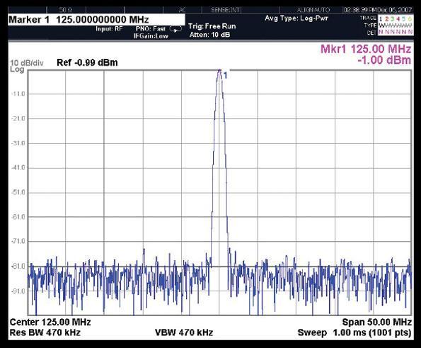
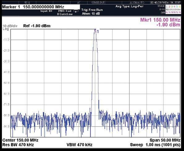
8 8 (c) 4. The spectral purity of the AD9910 DDS device is shown here at 125, 150, and 175 MHz. Principal sources of spurious signals at the DDS output are DAC resolution and tuning word bit truncation. 4 Elimination of spurious signals due to tuning word bit truncation may be accomplished with the attendant consequence of reduced frequency resolution. 1 Using this technique, the LFM architecture may be appropriate for several other high-spectral-quality applications. Figure 5 shows a block diagram of the linear FM frequency synthesizer, where the constituent components and interconnections have been identified. The AD DDS integrated circuit (IC) provides the agile frequency capability as well as the low phase noise reference for the offset PLL. The AD9910 features are uniquely applicable to linear FM due to a user defined, digitally controlled, digital ramp mode of operation. In this mode, the frequency, phase, or amplitude can be varied linearly over time. The AD9910 also features a 14-b, 1.0-GHz sample DAC and clock capability which provides a maximum output frequency of 400 MHz and greater than
9 -80 dbc spurious-free dynamic range. A wide loop bandwidth (3 MHz) is required to accurately track the reference signal frequency agility and assures phase continuous frequency agility for modest frequency steps This block diagram represents a linear FM frequency synthesizer operating at a clock frequency of 1 GHz. The clock source is a commercial SAW oscillator. A low-noise, commercial 1.0-GHz surface-acoustic-wave (SAW) oscillator was used to provide the DDS clock as well as the reference for the offset loop local oscillator via frequency multiplication using a step recovery diode. Under linear sweep operation, the AD9910 is dynamically tuned from 125 to 175 MHz using the digital ramp generator feature. In accordance with the output frequency equation, the offset loop and feedback modulus produce an output signal frequency from to GHz. f out = [(FTW/2 n )N + M]f ref where: FTW = the frequency tuning word (binary); n = the FTW resolution (32 b); N = the feedback loop modulus (N = 5);

10 M = the offset loop frequency multiplier factor (M = 12); and f clk = the clock frequency (f clk = 1.00 GHz). The feedback loop modulus is fixed at five but could be altered to extended synthesizer bandwidth, although this feature may require use of a switched filter bank to reduce spurious content. The offset loop effectively reduces the feedback loop modulus from 85 to 5, thereby lowering the phase noise by 24.5 db within the loop bandwidth. The component elements of the loop filter are specifically delineated to emphasize that accurate tracking and frequency agility of the AD9910 can only be assured with a wideband loop; in addition, and more specifically, the loop damping must be greater than critical i.e., > to prevent transient overshoot and assure asymptotic settling. 10 (a)
 spectral quality of the LFM synthesizer under narrow and wideband conditions.")
11 11 (b) 6. These plots show (a) the narrowband and (b) the wideband spectra for the LMF synthesizer. Figure 6 represents the center frequency (12.75 GHz) spectral quality of the LFM synthesizer under narrow and wideband conditions. The phase noise of the narrow band spectrum (-108 dbc/hz offset 100 khz from the carrier) is near the phase noise floor of the spectrum analyzer. An estimate of the phase noise from the wideband spectrum indicates phase noise measurement (-124 dbc/hz offset 1.0 MHz offset frequency) which correlates well with the phase noise estimate (-128 dbc/hz) in accordance with refs. 2 and 5.
")
12 (a) 12 (b)
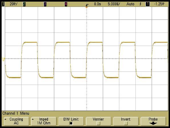
13 7. The dynamic response of the LFM synthesizer is shown for (a) a 250-MHz sweep in 50-kHz steps at a 4-ns dwell time and for (b) 10-MHz steps with 5-μs dwell time. The dynamic closed-loop response of the LFM synthesizer is indicated in Fig. 7 for two ramp generator configurations: (a) a total sweep of 250 MHz using 50,000 steps of 5.0 khz and 4-ns dwell time; (b) 10-MHz frequency deviation using two-steps and 5.0-μs dwell time at each step-note frequency settling less than 1 μs. The time waveforms of Fig. 7 represent the VCO control voltage under the indicated frequency agile conditions. For the conditions specified in Fig. 7(a), the maximum deviation from linear frequency versus time may be calculated using the formula of Eq. 5: 1 frequencysweeplinear(%) = (Δf/ΔF)100 = ( )/( )100 = 0.002% (5) This is extraordinary linearity performance and ensures that the radar range measurement resolution is not degraded due to spectral spread following signal processing The effectiveness of the DDS based LFM synthesizer as a transmitter and receiver local oscillator source for FMCW radar may be determined with the closed-loop equipment configuration of Fig. 8, where the LFM synthesizer output provides the local oscillator drive signal for a double-balanced mixer as well as a received signal. The received signal is delayed via 100 ft. of RG-141 semirigid cable. 7
14 8. This diagram represents the test system for closed-loop evaluation of the LFM synthesizer. The IF at the mixer output can be calculated by Eq. 6: f if = (ΔF/ΔT)τ d = khz (6) The equipment produces an IF signal proportional to the ramp rate and the time delay associated with the cable. The output signal is spectrally resolved to qualitatively determine the linearity and, possibly, the phase noise. The results of the closed-loop test are shown in Fig. 8. Test parameters, collected from a Hamming window analysis, include frequency deviation of 250 MHz, scan time of s, sample rate of 1 MSamples/s, FFT length of 10,000 points, frequency resolution of 100 Hz, range resolution of 83 Hz/m, and cable delay of 145 ns. 14 Figure 8(a) represents the IF spectrum of the LFM source and Fig. 8(b) is the IF spectrum following substitution of the model E8257D8 signal generator as the source for the closed-loop test. Close examination of Fig. 8 reveals higher signal-to-noise ratio and narrower spectral width of the LFM synthesizer IF spectrum. The closedloop equipment functions as an FM discriminator. Therefore, the broader spectral width of the IF signal using the E8257D signal generator is indicative of higher residual FM noise and/or degraded linearity, since both conditions will extend the width of the IF signal spectrum. The lower signal level in the IF spectrum of the E8257D indicates that signal energy is distributed to adjacent frequency bins of the spectrum.
15 (a) 15 (b) 9. The LFM synthesizer performance is plotted for Δf of 25 MHz and ΔT of 10 ms for (a) the LFM source and (b) a commercial signal generator, model E8257D from Agilent Technologies.

16 This photograph shows the RF section of the LFM synthesizer. Although the test methodology is somewhat subjective, the results provide credible evidence of the quality and suitability of the LFM synthesizer to function effectively as a source for FMCW radar, as well as other frequency agile applications. 7 Figure 9 offers a view of the RF section of the LFM synthesizer, revealing the use of discrete and surface-mount components. Support electronics, power supply conditioning, and control interface/functions are integrated on the lower surface (not shown). Isolation walls and energetic grounding techniques are clearly illustrated and required to reduce spurious signals. The source features low-loss microstrip line fabricated on RO4350 circuit substrate material from Rogers Corp. The RF section of the synthesizer is approximately in. (Fig. 10). To ensure adequate coupling and isolation, attempts were not made to reduce the size of the synthesizer. Kenneth V. Puglia, Principal E H Consulting Services, 146 Westview Dr., Westford, MA 01886; (978) , kvpuglia@verizon.net.
17 Acknowledgments The work reported within the article was conducted by the author while employed at M/A-COM in The author acknowledges the diligence of Scott Crawford and Chris Monroy in assembly, breadboard, and measurement tasks, as well as Bert Henderson (from M/A-COM in San Jose, CA and formerly of Watkins-Johnson Co.) for analysis, design, and prototypes of the X-band filters. The author acknowledges and appreciates the generous and timely support of Hittite Microwave Corp. (Chelmsform, MA); rapid acquisition of MMIC devices and evaluation boards was significant in validation of the LFM synthesizer architecture and management of an aggressive program schedule. References 1. Kenneth V. Puglia, Technical Memorandum: FMCW Radar Primer, M/A-COM GmbH, Schweinfurt, Germany; August Keneth V. Puglia, Technical Memorandum: Transmitter FM Noise and Frequency Sweep Nonlinearity in FMCW Radar, M/A-COM, GmbH, Schweinfurt, Germany, July, Technical Tutorial on Digital Signal Synthesis, Analog Devices, Inc., 1999, 4. Ulrich L. Rohde and Ajay Kumar Poddar, VCSO Technology Silences Synthesizers, Microwaves & RF, Vol. 50, No. 2, February, Kenneth V. Puglia, Oscillator Phase Noise: Theory and Prediction, Microwave Journal, Vol. 50, No. 9, September, 2007, pp Analog Devices, AD9910 data sheet, 7. D. Scherer, Design Principles and Test Methods for Low Noise RF and Microwave Sources, Hewlett-Packard RF and Microwave Measurement Symposium, October, For additional reading H.D. Griffiths, New Ideas in FM Radar, Electronics and Communication Engineering Journal, October 1990, pp A.G. Stove, Linear FMCW Radar Techniques, IEE Proceeding-F, Vol. 139, No. 5, October 1992, pp
18 J. Figueras Ventura and H. Russchenberg, Improvement of the Performance of FM- CW Radar Systems by using Direct Digital Synthesizers: Comparison with Voltage Controlled Oscillators, available via IEEE Explore. D. Morgan, P.D.L. Beasley, K.E. Ball, and W.P. Jones, Exploitation of direct digital synthesis for sweep generation in FMCW radar, ARMMS Conference, November, 7-8, 2005, Newport Pagnell, England. Μετα τιμής Βλαχάκης Μιχαήλ Επιστημονικός Συνεργάτης Cretasoft.gr Τμ.Επ. Υπολογ. Π.Κρήτης Τηλ BSC Φυσικομαθηματική Σχολή Π.Κρήτης
A 3 TO 30 MHZ HIGH-RESOLUTION SYNTHESIZER CONSISTING OF A DDS, DIVIDE-AND-MIX MODULES, AND A M/N SYNTHESIZER. Richard K. Karlquist
 A 3 TO 30 MHZ HIGH-RESOLUTION SYNTHESIZER CONSISTING OF A DDS, -AND-MIX MODULES, AND A M/N SYNTHESIZER Richard K. Karlquist Hewlett-Packard Laboratories 3500 Deer Creek Rd., MS 26M-3 Palo Alto, CA 94303-1392
Fabricate a 2.4-GHz fractional-n synthesizer
 University of Malaya From the SelectedWorks of Professor Mahmoud Moghavvemi Summer June, 2013 Fabricate a 2.4-GHz fractional-n synthesizer H Ameri Mahmoud Moghavvemi, University of Malaya a Attaran Available
Local Oscillator Phase Noise and its effect on Receiver Performance C. John Grebenkemper
 Watkins-Johnson Company Tech-notes Copyright 1981 Watkins-Johnson Company Vol. 8 No. 6 November/December 1981 Local Oscillator Phase Noise and its effect on Receiver Performance C. John Grebenkemper All
Phase Noise and Tuning Speed Optimization of a MHz Hybrid DDS-PLL Synthesizer with milli Hertz Resolution
 Phase Noise and Tuning Speed Optimization of a 5-500 MHz Hybrid DDS-PLL Synthesizer with milli Hertz Resolution BRECHT CLAERHOUT, JAN VANDEWEGE Department of Information Technology (INTEC) University of
A COMPACT, AGILE, LOW-PHASE-NOISE FREQUENCY SOURCE WITH AM, FM AND PULSE MODULATION CAPABILITIES
 A COMPACT, AGILE, LOW-PHASE-NOISE FREQUENCY SOURCE WITH AM, FM AND PULSE MODULATION CAPABILITIES Alexander Chenakin Phase Matrix, Inc. 109 Bonaventura Drive San Jose, CA 95134, USA achenakin@phasematrix.com
AN X-BAND FREQUENCY AGILE SOURCE WITH EXTREMELY LOW PHASE NOISE FOR DOPPLER RADAR
 AN X-BAND FREQUENCY AGILE SOURCE WITH EXTREMELY LOW PHASE NOISE FOR DOPPLER RADAR H. McPherson Presented at IEE Conference Radar 92, Brighton, Spectral Line Systems Ltd England, UK., October 1992. Pages
f o Fig ECE 6440 Frequency Synthesizers P.E. Allen Frequency Magnitude Spectral impurity Frequency Fig010-03
 Lecture 010 Introduction to Synthesizers (5/5/03) Page 010-1 LECTURE 010 INTRODUCTION TO FREQUENCY SYNTHESIZERS (References: [1,5,9,10]) What is a Synthesizer? A frequency synthesizer is the means by which
20 MHz-3 GHz Programmable Chirp Spread Spectrum Generator for a Wideband Radio Jamming Application
 J Electr Eng Technol Vol. 9, No.?: 742-?, 2014 http://dx.doi.org/10.5370/jeet.2014.9.?.742 ISSN(Print) 1975-0102 ISSN(Online) 2093-7423 20 MHz-3 GHz Programmable Chirp Spread Spectrum Generator for a Wideband
Section 1. Fundamentals of DDS Technology
 Section 1. Fundamentals of DDS Technology Overview Direct digital synthesis (DDS) is a technique for using digital data processing blocks as a means to generate a frequency- and phase-tunable output signal
Agile Low-Noise Frequency Synthesizer A. Ridenour R. Aurand Spectrum Microwave
 Agile Low-Noise Frequency Synthesizer A. Ridenour R. Aurand Spectrum Microwave Abstract Simultaneously achieving low phase noise, fast switching speed and acceptable levels of spurious outputs in microwave
Keysight Technologies
 Keysight Technologies Generating Signals Basic CW signal Block diagram Applications Analog Modulation Types of analog modulation Block diagram Applications Digital Modulation Overview of IQ modulation
Design of Transmitter-Receiver for FM-CW Imaging Radar at L-band
 Design of Transmitter-Receiver for FM-CW Imaging Radar at L-band Ashish Kr. Roy 2, Bakul Bapat 1, C. Bhattacharya 1 and S.A.Gangal 2 1 Electronics Engineering Dept, DIAT, Pune - 411025, India 2 Department
Integrated Circuit Design for High-Speed Frequency Synthesis
 Integrated Circuit Design for High-Speed Frequency Synthesis John Rogers Calvin Plett Foster Dai ARTECH H O US E BOSTON LONDON artechhouse.com Preface XI CHAPTER 1 Introduction 1 1.1 Introduction to Frequency
Application Note #5 Direct Digital Synthesis Impact on Function Generator Design
 Impact on Function Generator Design Introduction Function generators have been around for a long while. Over time, these instruments have accumulated a long list of features. Starting with just a few knobs
A new method of spur reduction in phase truncation for DDS
 A new method of spur reduction in phase truncation for DDS Zhou Jianming a) School of Information Science and Technology, Beijing Institute of Technology, Beijing, 100081, China a) zhoujm@bit.edu.cn Abstract:
Introduction. In the frequency domain, complex signals are separated into their frequency components, and the level at each frequency is displayed
 SPECTRUM ANALYZER Introduction A spectrum analyzer measures the amplitude of an input signal versus frequency within the full frequency range of the instrument The spectrum analyzer is to the frequency
Model 7000 Series Phase Noise Test System
 Established 1981 Advanced Test Equipment Rentals www.atecorp.com 800-404-ATEC (2832) Model 7000 Series Phase Noise Test System Fully Integrated System Cross-Correlation Signal Analysis to 26.5 GHz Additive
This article reports on
 Millimeter-Wave FMCW Radar Transceiver/Antenna for Automotive Applications A summary of the design and performance of a 77 GHz radar unit David D. Li, Sam C. Luo and Robert M. Knox Epsilon Lambda Electronics
Hybrid Frequency Synthesizer Combines Octave Tuning Range and Millihertz Steps
 Hybrid Frequency Synthesizer Combines Octave Tuning Range and Millihertz Steps DDS and PLL techniques are combined in this high-resolution synthesizer By Benjamin Sam Analog Devices Northwest Laboratories
Section 8. Replacing or Integrating PLL s with DDS solutions
 Section 8. Replacing or Integrating PLL s with DDS solutions By Rick Cushing, Applications Engineer, Analog Devices, Inc. DDS vs Standard PLL PLL (phase-locked loop) frequency synthesizers are long-time
APPH6040B / APPH20G-B Specification V2.0
 APPH6040B / APPH20G-B Specification V2.0 (July 2014, Serial XXX-XX33XXXXX-XXXX or higher) A fully integrated high-performance cross-correlation signal source analyzer for to 7 or 26 GHz 1 Introduction
Direct Digital Synthesis Primer
 Direct Digital Synthesis Primer Ken Gentile, Systems Engineer ken.gentile@analog.com David Brandon, Applications Engineer David.Brandon@analog.com Ted Harris, Applications Engineer Ted.Harris@analog.com
GT 9000 GT 9000S MICROWAVE
 Page 1 of 6 GT 9000 GT 9000S MICROWAVE Now you can get the performance you need and the capability you want, at a price you can afford. Both the Giga-tronics GT9000 Microwave Synthe- techniques.together,
Lecture 6. Angle Modulation and Demodulation
 Lecture 6 and Demodulation Agenda Introduction to and Demodulation Frequency and Phase Modulation Angle Demodulation FM Applications Introduction The other two parameters (frequency and phase) of the carrier
LNS ultra low phase noise Synthesizer 8 MHz to 18 GHz
 LNS ultra low phase noise Synthesizer 8 MHz to 18 GHz Datasheet The LNS is an easy to use 18 GHz synthesizer that exhibits outstanding phase noise and jitter performance in a 3U rack mountable chassis.
ADVANCED WAVEFORM GENERATION TECHNIQUES FOR ATE
 ADVANCED WAVEFORM GENERATION TECHNIQUES FOR ATE Christopher D. Ziomek Emily S. Jones ZTEC Instruments, Inc. 7715 Tiburon Street NE Albuquerque, NM 87109 Abstract Comprehensive waveform generation is an
Introduction to Single Chip Microwave PLLs
 Introduction to Single Chip Microwave PLLs ABSTRACT Synthesizer and Phase Locked Loop (PLL) figures of merit including phase noise spurious output and lock time at microwave frequencies are examined Measurement
Glossary of VCO terms
 Glossary of VCO terms VOLTAGE CONTROLLED OSCILLATOR (VCO): This is an oscillator designed so the output frequency can be changed by applying a voltage to its control port or tuning port. FREQUENCY TUNING
Multiple Reference Clock Generator
 A White Paper Presented by IPextreme Multiple Reference Clock Generator Digitial IP for Clock Synthesis August 2007 IPextreme, Inc. This paper explains the concept behind the Multiple Reference Clock Generator
A FREQUENCY SYNTHESIZER STRUCTURE BASED ON COINCIDENCE MIXER
 3 A FREQUENCY SYNTHESIZER STRUCTURE BASED ON COINCIDENCE MIXER Milan STORK University of West Bohemia UWB, P.O. Box 314, 30614 Plzen, Czech Republic stork@kae.zcu.cz Keywords: Coincidence, Frequency mixer,
Direct Digital Synthesis
 Tutorial Tutorial The HP 33120A is capable of producing a variety of signal waveshapes. In order to achieve the greatest performance from the function generator, it may be helpful if you learn more about
EE470 Electronic Communication Theory Exam II
 EE470 Electronic Communication Theory Exam II Open text, closed notes. For partial credit, you must show all formulas in symbolic form and you must work neatly!!! Date: November 6, 2013 Name: 1. [16%]
Understanding Low Phase Noise Signals. Presented by: Riadh Said Agilent Technologies, Inc.
 Understanding Low Phase Noise Signals Presented by: Riadh Said Agilent Technologies, Inc. Introduction Instabilities in the frequency or phase of a signal are caused by a number of different effects. Each
Radio Receiver Architectures and Analysis
 Radio Receiver Architectures and Analysis Robert Wilson December 6, 01 Abstract This article discusses some common receiver architectures and analyzes some of the impairments that apply to each. 1 Contents
Phase-Locked Loop Engineering Handbook for Integrated Circuits
 Phase-Locked Loop Engineering Handbook for Integrated Circuits Stanley Goldman ARTECH H O U S E BOSTON LONDON artechhouse.com Preface Acknowledgments xiii xxi CHAPTER 1 Cetting Started with PLLs 1 1.1
RF Signal Generators. SG380 Series DC to 2 GHz, 4 GHz and 6 GHz analog signal generators. SG380 Series RF Signal Generators
 RF Signal Generators SG380 Series DC to 2 GHz, 4 GHz and 6 GHz analog signal generators SG380 Series RF Signal Generators DC to 2 GHz, 4 GHz or 6 GHz 1 µhz resolution AM, FM, ΦM, PM and sweeps OCXO timebase
Session 3. CMOS RF IC Design Principles
 Session 3 CMOS RF IC Design Principles Session Delivered by: D. Varun 1 Session Topics Standards RF wireless communications Multi standard RF transceivers RF front end architectures Frequency down conversion
of Switzerland Analog High-Speed Products
 of Switzerland Analog High-Speed Products ANAPICO PRODUCTS 2012/2013 www.anapico.com Anapico Inc. is a growing Swiss manufacturer of leading edge products for RF test & measurement. The product ranges
Simulating and Testing of Signal Processing Methods for Frequency Stepped Chirp Radar
 Test & Measurement Simulating and Testing of Signal Processing Methods for Frequency Stepped Chirp Radar Modern radar systems serve a broad range of commercial, civil, scientific and military applications.
RF/IF Terminology and Specs
 RF/IF Terminology and Specs Contributors: Brad Brannon John Greichen Leo McHugh Eamon Nash Eberhard Brunner 1 Terminology LNA - Low-Noise Amplifier. A specialized amplifier to boost the very small received
APPLICATION NOTE 3942 Optimize the Buffer Amplifier/ADC Connection
 Maxim > Design Support > Technical Documents > Application Notes > Communications Circuits > APP 3942 Maxim > Design Support > Technical Documents > Application Notes > High-Speed Interconnect > APP 3942
Measurement Setup for Phase Noise Test at Frequencies above 50 GHz Application Note
 Measurement Setup for Phase Noise Test at Frequencies above 50 GHz Application Note Products: R&S FSWP With recent enhancements in semiconductor technology the microwave frequency range beyond 50 GHz becomes
Rigol DG1022A Function / Arbitrary Waveform Generator
 Rigol DG1022A Function / Arbitrary Waveform Generator The Rigol DG1000 series Dual-Channel Function/Arbitrary Waveform Generator adopts DDS (Direct Digital Synthesis) technology to provide stable, high-precision,
Advanced Test Equipment Rentals ATEC (2832) MG3690B. RF/Microwave Signal Generators, 0.1 Hz to 70 GHz/325 GHz
 MG3690B. RF/Microwave Signal Generators, 0.1 Hz to 70 GHz/325 GHz") Established 1981 Advanced Test Equipment Rentals www.atecorp.com 800-404-ATEC (2832) MG3690B RF/Microwave Signal Generators, 0.1 Hz to 70 GHz/325 GHz MG3690B Family Signal Generators Easy to Read backlit
Established 1981 Advanced Test Equipment Rentals www.atecorp.com 800-404-ATEC (2832) MG3690B RF/Microwave Signal Generators, 0.1 Hz to 70 GHz/325 GHz MG3690B Family Signal Generators Easy to Read backlit
FM cw Radar. FM cw Radar is a low cost technique, often used in shorter range applications"
 11: FM cw Radar 9. FM cw Radar 9.1 Principles 9.2 Radar equation 9.3 Equivalence to pulse compression 9.4 Moving targets 9.5 Practical considerations 9.6 Digital generation of wideband chirp signals FM
SC5306B 1 MHz to 3.9 GHz RF Downconverter Core Module. Datasheet SignalCore, Inc.
 SC5306B 1 MHz to 3.9 GHz RF Downconverter Core Module Datasheet 2015 SignalCore, Inc. support@signalcore.com SC5306B S PECIFICATIONS Definition of Terms The following terms are used throughout this datasheet
PHASE NOISE MEASUREMENT SYSTEMS
 PHASE NOISE MEASUREMENT SYSTEMS Item Type text; Proceedings Authors Lance, A. L.; Seal, W. D.; Labaar, F. Publisher International Foundation for Telemetering Journal International Telemetering Conference
New Features of IEEE Std Digitizing Waveform Recorders
 New Features of IEEE Std 1057-2007 Digitizing Waveform Recorders William B. Boyer 1, Thomas E. Linnenbrink 2, Jerome Blair 3, 1 Chair, Subcommittee on Digital Waveform Recorders Sandia National Laboratories
SPUR REDUCTION TECHNIQUES IN DIRECT DIGITAL SYNTHESIZERS
 Published in the Proceedings of the 1993 International Frequency Control Symposium. SPUR REDUCTION TECHNIQUES IN DIRECT DIGITAL SYNTHESIZERS Victor S. Reinhardt Hughes Space and Communications Company
Reconfigurable 6 GHz Vector Signal Transceiver with I/Q Interface
 SPECIFICATIONS PXIe-5645 Reconfigurable 6 GHz Vector Signal Transceiver with I/Q Interface Contents Definitions...2 Conditions... 3 Frequency...4 Frequency Settling Time... 4 Internal Frequency Reference...
A VCO-based analog-to-digital converter with secondorder sigma-delta noise shaping
 A VCO-based analog-to-digital converter with secondorder sigma-delta noise shaping The MIT Faculty has made this article openly available. Please share how this access benefits you. Your story matters.
Understanding RF and Microwave Analysis Basics
 Understanding RF and Microwave Analysis Basics Kimberly Cassacia Product Line Brand Manager Keysight Technologies Agenda µw Analysis Basics Page 2 RF Signal Analyzer Overview & Basic Settings Overview
Chapter 2 Architectures for Frequency Synthesizers
 Chapter 2 Architectures for Frequency Synthesizers 2.1 Overview This chapter starts with an overview of the conventional frequency synthesis techniques as well as the hybrid architectures that can be used
Ten-Tec Orion Synthesizer - Design Summary. Abstract
 Ten-Tec Orion Synthesizer - Design Summary Lee Jones 7/21/04 Abstract Design details of the low phase noise, synthesized, 1 st local oscillator of the Ten-Tec model 565 Orion transceiver are presented.
HF Receivers, Part 3
 HF Receivers, Part 3 Introduction to frequency synthesis; ancillary receiver functions Adam Farson VA7OJ View an excellent tutorial on receivers Another link to receiver principles NSARC HF Operators HF
Model 745 Series. Berkeley Nucleonics Test, Measurement and Nuclear Instrumentation since Model 845-HP Datasheet BNC
 Model 845-HP Datasheet Model 745 Series Portable 20+ GHz Microwave Signal Generator High Power +23dBM Power Output 250 fs Digital Delay Generator BNC Berkeley Nucleonics Test, Measurement and Nuclear Instrumentation
How To Design RF Circuits - Synthesisers
 How To Design RF Circuits - Synthesisers Steve Williamson Introduction Frequency synthesisers form the basis of most radio system designs and their performance is often key to the overall operation. This
SC5407A/SC5408A 100 khz to 6 GHz RF Upconverter. Datasheet. Rev SignalCore, Inc.
 SC5407A/SC5408A 100 khz to 6 GHz RF Upconverter Datasheet Rev 1.2 2017 SignalCore, Inc. support@signalcore.com P R O D U C T S P E C I F I C A T I O N S Definition of Terms The following terms are used
Receiver Architecture
 Receiver Architecture Receiver basics Channel selection why not at RF? BPF first or LNA first? Direct digitization of RF signal Receiver architectures Sub-sampling receiver noise problem Heterodyne receiver
MAKING TRANSIENT ANTENNA MEASUREMENTS
 MAKING TRANSIENT ANTENNA MEASUREMENTS Roger Dygert, Steven R. Nichols MI Technologies, 1125 Satellite Boulevard, Suite 100 Suwanee, GA 30024-4629 ABSTRACT In addition to steady state performance, antennas
Keysight Technologies Making Accurate Intermodulation Distortion Measurements with the PNA-X Network Analyzer, 10 MHz to 26.5 GHz
 Keysight Technologies Making Accurate Intermodulation Distortion Measurements with the PNA-X Network Analyzer, 10 MHz to 26.5 GHz Application Note Overview This application note describes accuracy considerations
UNIT-3. Electronic Measurements & Instrumentation
 UNIT-3 1. Draw the Block Schematic of AF Wave analyzer and explain its principle and Working? ANS: The wave analyzer consists of a very narrow pass-band filter section which can Be tuned to a particular
Keysight Technologies Pulsed Antenna Measurements Using PNA Network Analyzers
 Keysight Technologies Pulsed Antenna Measurements Using PNA Network Analyzers White Paper Abstract This paper presents advances in the instrumentation techniques that can be used for the measurement and
AN EXTENDED PHASE-LOCK TECHNIQUE FOR AIDED ACQUISITION
 AN EXTENDED PHASE-LOCK TECHNIQUE FOR AIDED ACQUISITION Item Type text; Proceedings Authors Barbour, Susan Publisher International Foundation for Telemetering Journal International Telemetering Conference
Radio-Frequency Conversion and Synthesis (for a 115mW GPS Receiver)
") Radio-Frequency Conversion and Synthesis (for a 115mW GPS Receiver) Arvin Shahani Stanford University Overview GPS Overview Frequency Conversion Frequency Synthesis Conclusion GPS Overview: Signal Structure
Radio-Frequency Conversion and Synthesis (for a 115mW GPS Receiver) Arvin Shahani Stanford University Overview GPS Overview Frequency Conversion Frequency Synthesis Conclusion GPS Overview: Signal Structure
Agilent 8360B/8360L Series Synthesized Swept Signal/CW Generators 10 MHz to 110 GHz
 Agilent 8360B/8360L Series Synthesized Swept Signal/CW Generators 10 MHz to 110 GHz ity. l i t a ers V. n isio c e r P. y t i l i ib Flex 2 Agilent 8360 Synthesized Swept Signal and CW Generator Family
Model 855 RF / Microwave Signal Generator
 Features Very low phase noise Fast switching Phase coherent switching option 2 to 8 phase coherent outputs USB, LAN, GPIB interfaces Applications Radar simulation Quantum computing High volume automated
Developing a Generic Software-Defined Radar Transmitter using GNU Radio
 Developing a Generic Software-Defined Radar Transmitter using GNU Radio A thesis submitted in partial fulfilment of the requirements for the degree of Master of Sciences (Defence Signal Information Processing)
RF Signal Generators. SG380 Series DC to 2 GHz, 4 GHz and 6 GHz analog signal generators. SG380 Series RF Signal Generators
 RF Signal Generators SG380 Series DC to 2 GHz, 4 GHz and 6 GHz analog signal generators SG380 Series RF Signal Generators DC to 2 GHz, 4 GHz or 6 GHz 1 μhz resolution AM, FM, ΦM, PM and sweeps OCXO timebase
THE UNIVERSITY OF NAIROBI
 THE UNIVERSITY OF NAIROBI ELECTRICAL AND INFORMATION ENGINEERING DEPARTMENT FINAL YEAR PROJECT. PROJECT NO. 085. TITLE: A PHASE-LOCKED LOOP FREQUENCY SYNTHESIZER BY: TUNDULI W. MICHAEL F17/2143/2004. SUPERVISOR:
Agilent AN 1275 Automatic Frequency Settling Time Measurement Speeds Time-to-Market for RF Designs
 Agilent AN 1275 Automatic Frequency Settling Time Measurement Speeds Time-to-Market for RF Designs Application Note Fast, accurate synthesizer switching and settling are key performance requirements in
Wideband Frequency Synthesizer Implementation using FPGA
 GRD Journals- Global Research and Development Journal for Engineering Volume 2 Issue 7 June 2017 ISSN: 2455-5703 Wideband Frequency Synthesizer Implementation using FPGA Jasmanpreet Singh Mrs. Monika Aggarwal
note application Fractional-N Synthesizers David Owen
 David Owen application note IFR (and formerly Marconi Instruments) owns the key IPR associated with Fractional-N synthesis technology. This application note provides historical information on fractional-n
Simplified Analogue Realization of the Digital Direct Synthesis (DDS) Technique for Signal Generation
 Technique for Signal Generation") IOSR Journal of Electrical and Electronics Engineering (IOSR-JEEE) e-issn: 2278-1676,p-ISSN: 2320-3331, Volume 9, Issue 2 Ver. VI (Mar Apr. 2014), PP 85-89 Simplified Analogue Realization of the Digital
IOSR Journal of Electrical and Electronics Engineering (IOSR-JEEE) e-issn: 2278-1676,p-ISSN: 2320-3331, Volume 9, Issue 2 Ver. VI (Mar Apr. 2014), PP 85-89 Simplified Analogue Realization of the Digital
ARMMS RF and Microwave Society Meeting April 4 th and 5 th Milton Hill House Steventon. Oxfordshire United Kingdom.
 ARMMS RF and Microwave Society Meeting April 4 th and 5 th Milton Hill House Steventon. Oxfordshire United Kingdom. Some Interesting Applications of Harmonic Mixers. David Williams. Teledyne Microwave
note application Measurement of Frequency Stability and Phase Noise by David Owen
 application Measurement of Frequency Stability and Phase Noise note by David Owen The stability of an RF source is often a critical parameter for many applications. Performance varies considerably with
Analog signal generator that meets virtually every requirement
 GENERAL PURPOSE 44434/5 FIG 1 The R&S SMA1A offers excellent performance and compact design at a favorable price. Signal Generator R&S SMA1A Analog signal generator that meets virtually every requirement
Lab Assignment #3 Analog Modulation (An Introduction to RF Signal, Noise and Distortion Measurements in the Frequency Domain)
") Lab Assignment #3 Analog Modulation (An Introduction to RF Signal, Noise and Distortion Measurements in the Frequency Domain) By: Timothy X Brown, Olivera Notaros, Nishant Jadhav TLEN 5320 Wireless Systems
Lab Assignment #3 Analog Modulation (An Introduction to RF Signal, Noise and Distortion Measurements in the Frequency Domain) By: Timothy X Brown, Olivera Notaros, Nishant Jadhav TLEN 5320 Wireless Systems
Low distortion signal generator based on direct digital synthesis for ADC characterization
 ACTA IMEKO July 2012, Volume 1, Number 1, 59 64 www.imeko.org Low distortion signal generator based on direct digital synthesis for ADC characterization Walter F. Adad, Ricardo J. Iuzzolino Instituto Nacional
SPECIFICATION FREQUENCY RANGE: IBS-6
 IBS Series SYNTHESIZER SPECIFICATION FREQUENCY RANGE: IBS-6 0.1 to 6 GHz IBS-18 2 to 18 GHz IBS-20 0.1 to 20 GHz FEATURES Wide Frequency Bandwidth: 0.1 to 20 GHz Fast Switching Speed: 200 usec, Full Band
SC5307A/SC5308A 100 khz to 6 GHz RF Downconverter. Datasheet SignalCore, Inc.
 SC5307A/SC5308A 100 khz to 6 GHz RF Downconverter Datasheet 2017 SignalCore, Inc. support@signalcore.com P RODUCT S PECIFICATIONS Definition of Terms The following terms are used throughout this datasheet
GHz-band, high-accuracy SAW resonators and SAW oscillators
 The evolution of wireless communications and semiconductor technologies is spurring the development and commercialization of a variety of applications that use gigahertz-range frequencies. These new applications
ELT Receiver Architectures and Signal Processing Exam Requirements and Model Questions 2018
 TUT/ICE 1 ELT-44006 Receiver Architectures and Signal Processing Exam Requirements and Model Questions 2018 General idea of these Model Questions is to highlight the central knowledge expected to be known
Lecture 11. Phase Locked Loop (PLL): Appendix C. EE4900/EE6720 Digital Communications
: Appendix C. EE4900/EE6720 Digital Communications") EE4900/EE6720: Digital Communications 1 Lecture 11 Phase Locked Loop (PLL): Appendix C Block Diagrams of Communication System Digital Communication System 2 Informatio n (sound, video, text, data, ) Transducer
EE4900/EE6720: Digital Communications 1 Lecture 11 Phase Locked Loop (PLL): Appendix C Block Diagrams of Communication System Digital Communication System 2 Informatio n (sound, video, text, data, ) Transducer
6.976 High Speed Communication Circuits and Systems Lecture 17 Advanced Frequency Synthesizers
 6.976 High Speed Communication Circuits and Systems Lecture 17 Advanced Frequency Synthesizers Michael Perrott Massachusetts Institute of Technology Copyright 2003 by Michael H. Perrott Bandwidth Constraints
Advances in RF and Microwave Measurement Technology
 1 Advances in RF and Microwave Measurement Technology Chi Xu Certified LabVIEW Architect Certified TestStand Architect New Demands in Modern RF and Microwave Test In semiconductor and wireless, technologies
Analysis of Phase Noise Profile of a 1.1 GHz Phase-locked Loop
 Analysis of Phase Noise Profile of a 1.1 GHz Phase-locked Loop J. Handique, Member, IAENG and T. Bezboruah, Member, IAENG 1 Abstract We analyzed the phase noise of a 1.1 GHz phaselocked loop system for
ACTIVE MULTIPLIERS AND DIVIDERS TO SIMPLIFY SYNTHESIZERS
 7 COVER FEATURE ACTIVE MUTIPIERS & DIVIDERS ACTIVE MUTIPIERS AND DIVIDERS TO SIMPIFY SYNTHESIZERS M odern frequency synthesis uses a combination of frequency multiplication and frequency division to generate
Using an Arbitrary Waveform Generator for Threat Generation
 Application Note - Using an Arbitrary Waveform Generator for Threat Generation Authors: Mark Elo, Giga-tronics & Christopher Loberg, Tektronix Published: August 1, 2015 Revision: A Introduction An arbitrary
Development of Signal Analyzer MS2840A with Built-in Low Phase-Noise Synthesizer
 Development of Signal Analyzer MS2840A with Built-in Low Phase-Noise Synthesizer Toru Otani, Koichiro Tomisaki, Naoto Miyauchi, Kota Kuramitsu, Yuki Kondo, Junichi Kimura, Hitoshi Oyama [Summary] Evaluation
Antenna Measurements using Modulated Signals
 Antenna Measurements using Modulated Signals Roger Dygert MI Technologies, 1125 Satellite Boulevard, Suite 100 Suwanee, GA 30024-4629 Abstract Antenna test engineers are faced with testing increasingly
ECEN 5014, Spring 2013 Special Topics: Active Microwave Circuits and MMICs Zoya Popovic, University of Colorado, Boulder
 ECEN 5014, Spring 2013 Special Topics: Active Microwave Circuits and MMICs Zoya Popovic, University o Colorado, Boulder LECTURE 13 PHASE NOISE L13.1. INTRODUCTION The requency stability o an oscillator
Radiofrequency Measurements. Frequency Synthesizers
 Radiofrequency Measurements Frequency Synthesizers The next slides material is taken from AGILENT Fundamentals of Quartz Oscillators, Application Note 200-2 AGILENT Source Basics John R. Vig Quartz Crystal
Twelve voice signals, each band-limited to 3 khz, are frequency -multiplexed using 1 khz guard bands between channels and between the main carrier
 Twelve voice signals, each band-limited to 3 khz, are frequency -multiplexed using 1 khz guard bands between channels and between the main carrier and the first channel. The modulation of the main carrier
UNIT 2. Q.1) Describe the functioning of standard signal generator. Ans. Electronic Measurements & Instrumentation
 Describe the functioning of standard signal generator. Ans. Electronic Measurements & Instrumentation") UNIT 2 Q.1) Describe the functioning of standard signal generator Ans. STANDARD SIGNAL GENERATOR A standard signal generator produces known and controllable voltages. It is used as power source for the
UNIT 2 Q.1) Describe the functioning of standard signal generator Ans. STANDARD SIGNAL GENERATOR A standard signal generator produces known and controllable voltages. It is used as power source for the
PXIe Contents CALIBRATION PROCEDURE. Reconfigurable 6 GHz RF Vector Signal Transceiver with 200 MHz Bandwidth
 IBRATION PROCEDURE PXIe-5646 Reconfigurable 6 GHz Vector Signal Transceiver with 200 MHz Bandwidth This document contains the verification and adjustment procedures for the PXIe-5646 vector signal transceiver.
PHASELOCK TECHNIQUES INTERSCIENCE. Third Edition. FLOYD M. GARDNER Consulting Engineer Palo Alto, California A JOHN WILEY & SONS, INC.
 PHASELOCK TECHNIQUES Third Edition FLOYD M. GARDNER Consulting Engineer Palo Alto, California INTERSCIENCE A JOHN WILEY & SONS, INC., PUBLICATION CONTENTS PREFACE NOTATION xvii xix 1 INTRODUCTION 1 1.1
VHDL Implementation of High Performance Digital Up Converter Using Multi-DDS Technology For Radar Transmitters
 VHDL Implementation of High Performance Digital Up Converter Using Multi-DDS Technology For Radar Transmitters Ganji Ramu M. Tech Student, Department of Electronics and Communication Engineering, SLC s
Measuring ACPR of W-CDMA signals with a spectrum analyzer
 Measuring ACPR of W-CDMA signals with a spectrum analyzer When measuring power in the adjacent channels of a W-CDMA signal, requirements for the dynamic range of a spectrum analyzer are very challenging.
A 2.6GHz/5.2GHz CMOS Voltage-Controlled Oscillator*
 WP 23.6 A 2.6GHz/5.2GHz CMOS Voltage-Controlled Oscillator* Christopher Lam, Behzad Razavi University of California, Los Angeles, CA New wireless local area network (WLAN) standards have recently emerged