Introduction. A closed loop of wire is not an electrical circuit, a circuit requires
|
|
|
- Roberta Newton
- 5 years ago
- Views:
Transcription

1

2 The Law of Charges Opposite charges attract like charges repel Lines of force can never cross each other The values are equal but the effect is opposite Strength of the attraction is exponential to its distance The electron is attracted to the nucleus

3 Electron Flow When one electron knocks another electron from its orbit electron flow is produced When the atom has only one valence electron, it moves easier when struck The electron being struck will strike another and start a chain reaction
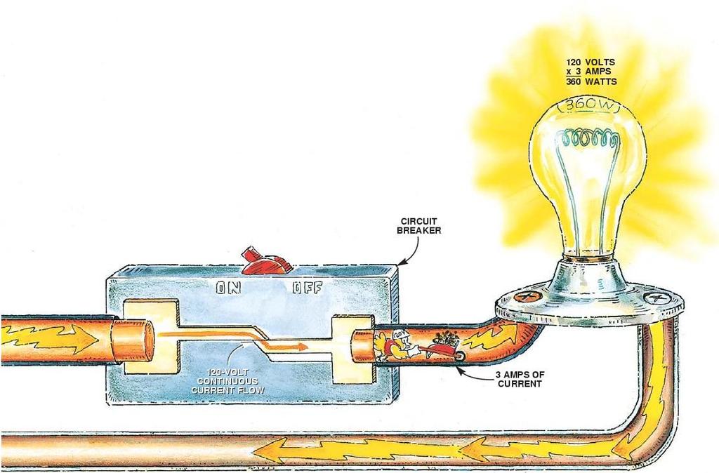
4 Introduction A closed loop of wire is not an electrical circuit, a circuit requires A power source A control method (switch) A load device (light bulb) A conductor A return path
5 Introduction Power source L1 Return path S w i t c h Conductor Load L2


6 Ampere Andre Ampere (a French scientist) determined One amp equals one Coulomb passing a point every second The letter A stands for amp The letter I stands for intensity We will use the letter I while using the amperage formulas to represent current
7 Electrical Circuits A complete path must exist for current to flow through a conductor
8 Electrical Circuits The load device provides the resistance and limits the amount of current flow
9 Electrical Circuits Open Circuits occur when a completed current path is opened by a switch or overload device (OCPD)

10 Electrical Circuits Any circuit that has no resistance creates excessive current is a Short Circuit

11 Electrical Circuits Any circuit that takes a different current path to complete the circuit is a Grounded Circuit

12 Grounding An appliance may short to ground making the cabinet or housing electrically energized With a green wire it has a current pathway to return to source The green wire is for your safety and must stay in the circuit

13 The Volt Voltage is Electromotive force (EMF) EMF is the pressure that pushes the current through the conductor If voltage were water it would be the pump The pipe would be the conductor and the resistance source The water would be considered the current flow We will be using the letter E to represent voltage during this class
14 Circuits 1. CAN BE DEFINED AS THE MEANS BY WHICH A DEVICE IS ACTUATED BY THE OPERATION OF SOME OTHER DEVICE TO WHICH IT IS ASSOCIATED: CIRCUIT INTERLOCKING
15 In 1981, the 32-watt T8 lamp was introduced in the United States, providing further improvements in 4-foot fluorescent lamps. Today, the T8 lamp is the standard for new construction and is a popular replacement for 34-watt T12 lamps. All major lamp manufacturers market T8 lamps of various wattages, and they are readily available in a variety of linear and U-shaped configurations. T-8 = 8 x 1/8 so 1 inch and t-12 = 1 ½ inch
16 Circuits PROVIDES A LOW VOLTAGE RELEASE AND LOW VOLTAGE PROTECTION: THREE-WIRE CIRCUITS
17 Circuits MOST CIRCUIT BREAKERS HAVE A CURRENT INTERRUPT CAPACITY OF 200,000 AMPS:
18 Circuits A SET OF NORMALLY OPEN RELAY CONTACTS ARE WHEN THE RELAY IS : OPEN, DE- ENERGIZED
19 Circuits CONTACTS SHOULD BE REPLACED:
20 Circuits. THE ARMATURES OF BOTH AC AND DC CONTACTORS MUST MOVE FREELY OR:
21 Circuits AN ELECTROMAGENT THAT HAS A MOVING ARMATURE INSIDE ITS OPERATING COIL IS DESIGNATED AS A: Solenoid
22 Circuits WHEN SEVERAL PUSHBUTTON STATIONS ARE TO PROVIDE THREEWIRE CONTROL OF A MOTOR THROUGH A MAGNETIC STARTER, CONNECT THEM SO THAT THE: The stop buttons are in series and the start buttons are in parallel
23 Circuits A RELAY IS A DEVICE WHICH CAN TRANSFER AN ACTION FROM ONE CIRCUIT TO ANOTHER WITHOUT AN ACTUAL ELECTRICAL CONNECTION BETWEEN THE TWO CIRCUITS: True
24 Circuits A WAY TO HELP CONFINE, DIVIDE, AND EXTINGUISH THE ARC FOR EACH SET OF CONTACTS IS TO USE: Arc Chutes
25 The Ohm The Ohm is a unit of resistance One Ohm is the amount of resistance that is required to allow one ampere of current to flow when one volt of power is applied to it Resistance is used to control current flow The higher the resistance the less the current flow Any time current flows through a resistor heat is generated We will be using the letter R to represent resistance

26 The Ohm Resistance is used to control current flow The higher the resistance the less the current flow

27 The Ohm Any time current flows through a resistor heat is generated We will be using the letter R to represent resistance
28 The wat Watts equal the amount of power being consumed To have Watts energy must be converted to either work or heat We will identify Watts with the letter P (power) for the duration of the class


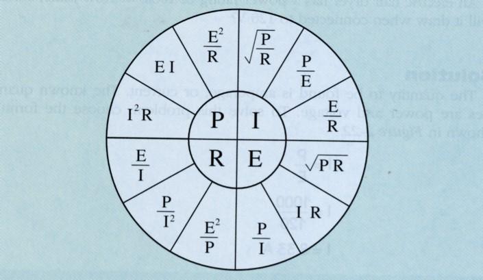
29 Ohm s Law A mathematical formula that shows that current is directly proportional to voltage and inversely proportional resistance. E=I X R P=E X I R=E / I E=P / I I=E / R I=P / E
30
31 CIRCUITS TIME DELAY DEVICES ARE USED IN THE OVERLOAD RELAYS OF MOTOR STARTERS TO ALLOW FOR THE HIGH INRUSH MOTOR CURRENTS: DURING THE STARTING PERIOD
32 CIRCUITS THE CURRENT RATING OF A CONTACTOR OR STARTER IS RATING FOR:
33 Circuits. WHEN IS IT SAID THAT CONTINUITY EXISTS IN A LADDER RUNG? WHEN THERE IS CURRENT FLOW FROM LEFT TO RIGHT
34 A SHORT-CIRCUIT GROUND-FAULT DEVICE MAY CONSIST OF: A fuse or circuit breaker
35 Circuits TO INDICATE A GOOD DIODE, AN OHMMETER SHOULD SHOW: LOW RESISTANCE IN ONE DIRECTION AND HIGH RESISTANCE IN THE OTHER
36 Circuits A MOTOR CONTROL CIRCUIT THAT ALLOWS THE MOTOR TO AUTOMATICALLY RESTART AFTER POWER IS RESTORED: Two wire
37 Circuits STARTERS AND CONTACTORS ARE BASICALLY THE SAME, BUT HAVE THERMAL OVERLOAD PROTECTION AND DON'T: Starters / contactors
38 Circuits THE VARIALBE- SPEED DRIVE CONTROLS THE SPEED OF A MOTOR BY PROVIDING A SUPPLY OF PHASE VOLTAGE FREQUENCY: AT A DIFFERENT
39 Circuits ALWAYS REMOVE THE COMPONENT TO BE TESTED OR DISCONNECT THE LINE VOLTAGE FROM THE CIRCUIT WHEN MAKING A: RESISTANCE MEARSUREMENT
40 Permanent Magnets Permanent magnets Will retain magnetic properties after the magnetizing force is removed Require no power to maintain their fields Are nickel, iron, or cobalt Spin on their axis opposite to the rotation of its nucleus (electron spin pattern)


41 Magnetism 2000 years ago the Greeks found magnetic stones (Magnetite) They found that the stone would always point north True magnets are called lodestones Magnetic north is not the same as true north Are the most important thing in electricity Relays, motors, instruments, valves use magnetism


42 Magnetic Line of Force Magnetic lines of force Lines of Flux Repel each other Never cross

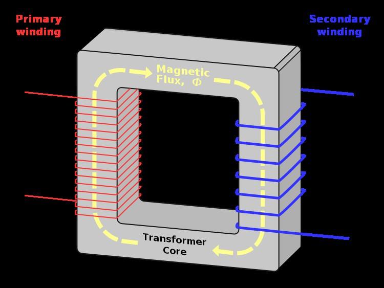
43 Electromagnets A basic law of physics states that whenever an electric current flows through a conductor, A magnetic field is formed around the conductor

44 Electromagnets If a conductor is wound into a coil, the magnetic lines of flux add to produce a stronger magnetic field. An increase in current flow will cause an increase in the magnetic field Ampere turns Multiply the number of turns by current flow The two factors that determine the number of flux lines produced by an electromagnet are the number turns of a wire and the amount of current flowing through the wire
45 Core Material Iron or Soft steel cores: Increases the strength of the magnet Reluctance: The measurement of a materials resistance to magnetism Saturation: A magnet is as strong as it can get Residual Magnetism: How much magnetic force is left after the current is removed Coercive Force or Retentivity The measurement of a materials ability to retain magnetism
46 Magnetic Measurement There are three different types of systems used to measure magnetism The English System Measures flux density The CGS System Centimeter-gram-second Measures one Maxwell The MKS System Meter-kilogram-second The unit of measurement is the dyne
47 Magnetism IS MADE WHEN AN ELECTRIC CURRENT FLOWS THROUGH THE TURNS OF A COIL? A MAGNETIC FIELD
48 Magnetism A MAGNET THAT LOSES ALMOST ALL ITS MAGNETISM AFTER THE MAGNETIZING FORCE HAS BEEN REMOVED IS CALLED: A TEMPORARY MAGNET
49 Magnetism IMPROPER ALIGNMENT OF THE POLE FACES CAN CAUSE EXCESSIVE HUM IN AN AC ELECTROMAGNET OR SOLENOID: True
50 Batteries
51 History 1791 Galvani: theorized that muscles worked by electricity 1800 Volta: Concluded that the chemical reaction of the copper, iron, and saltwater created the electricity in the frogs leg; not the other way around


52 Volta created the first battery The battery is constructed using zinc and silver discs separated by a piece of cardboard soaked in brine or saltwater. This new battery was called a voltaic pile because individual cells are assembled in series A battery is several cells connected together The schematic symbols for an individual cell (left) and for a battery (right)


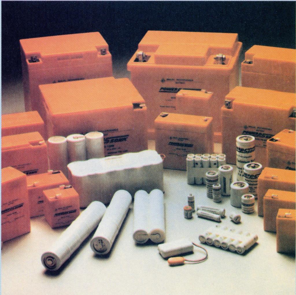
53 The amount of current a particular type of cell can deliver is determined by the surface area of its plates A D-cell can deliver more than a Ccell which can deliver more than an AA-cell This is called current capacity A rating used is the ma-hr Also the watt-hour W-h=mA*E A D cell= 1.5 volts with a 10,000 ma-hr 1.5*10,000=15,000mWhr Or 15 W-hr


54 Combinations can add voltage and current capacity Series: Adds voltage, current stays the same Parallel: Adds current, voltage stays the same

55 Magnetic Induction Whenever current flows a magnetic field is produced The direction of current flow determines the polarity of the magnet The amount of current determines the strength of the field
56 Magnetic Induction This same basic law in reverse is the principle of magnetic induction, which states that whenever a conductor cuts through magnetic lines of flux, a voltage is induced into the conductor.
57 Magnetic Induction When a conductor is moved up through a magnet field the current in the conductor moves one direction When the same conductor is moved down again the current flows in the opposite direction

58 The zero center-meter changes with the reverse in polarity, so we can say that the polarity of the induced voltage is determined by the magnetic field in relation to direction of movement.


59 The polarity of an induced voltage can also be changed by reversing the polarity of the magnetic field.

60 Moving Magnetic Fields The most important factors that relate to magnetic induction are a conductor, a magnetic field, and movement Most AC generators or alternators operate on the principle of a coil of wire held stationary while a magnet is moved through the coil as shown in the picture. When the lines of flux cut through the windings of the coil they induce a voltage into them

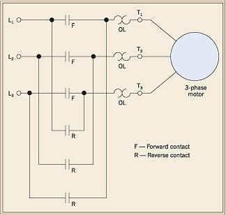
61 How to reverse a single phase motor The following is how you would reverse a 120-volt or 240 volt split-phase motor. Reverse the StartWinding leads or the Run-Winding leads, but not both. This will reverse the direction of rotation for a splitphase motor.

62 How to reverse a three phase motor To reverse the direction of a three-phase induction type motor, you can reverse the leads in the starter. T-1, T-2, T-3. For example: Reverse T1 and T-2, or Reverse T-1 and T-3, or Reverse T-2 and T-3.

63 Voltage increases if the speed of the rotation is increased or the conductor has more lines of flux A simple one-loop generator More lines of flux added to the loop more lines are cut per second

64 Inductance If the turn of a wire is far apart they will have less inductance than turns wound closer together
65 Bateries A LARGER BATTERY STORAGE CELL, AS COMPARED TO A SMALL ONE HAS A: LONGER LIFE
66 Bateries DISTILLED WATER SHOULD BE ADDED TO A BATTERY: WHEN LEVEL IS BELOW PLATES
67 Bateries A PHASE IMBALANCE CAN CAUSE THREEPHASE MOTORS TO RUN: AT HIGHER TEMEPRATURES
68 Bateries STORAGE BATTERIES ARE RATED FOR AMPERE-HOUR CAPACITY AND: VOLTAGE
69 Bateries THE ELECTRICAL ENERGY A BATTERY CAN DELIVER IS MEASURED IN: AMP-HOURS
70
71 Advantages of Alternating Current 1. AC current can be transformed 2. Transmission Voltages are very high


72 Thomas Edison advocated DC because it was safer. Alternating current won because it could be transmitted over long distances AC differs from DC in that it reverses direction of flow at periodic intervals One wave form frequently encountered is the square wave. Note the darker line on the illustration on the left Each time a voltage reverses polarity, the current flowing through the circuit changes direction. A square wave could be produced by a single pole-double throw switch connected to two batteries
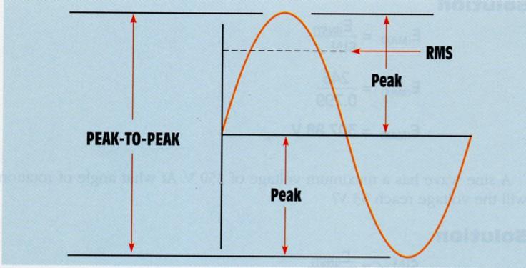
73 AC Wave Forms (Sine Wave) The most common form of alternating current is the sine wave. These waves are mostly created by rotating equipment
74 AC Wave Forms (Sine Wave) A complete sine wave contains 360 electrical degrees Reaches peak positive voltage at 900, 0 volts at 1800, maximum negative voltage at 2700,and returns to 0 volts at 3600 over a certain time interval, usually 60 cycles A cycle is the length of time it takes for a sine wave to complete one cycle We use 60 cycles in this country. 60Hz = 60 times per second
voltage being induced into the")
75 90 0 When the loop has rotated 900, it is perpendicular to the flux line and is cutting them at the maximum rate, which results in the maximum (peak)voltage being induced into the circuit
 E(inst)= E(max)* SIN E(max)= E(inst)/ SIN SIN = E(inst)/")
76 E(inst)=The voltage at any point on the wave form E(max)= The maximum or peak voltage SIN = The sine of the angle of rotation (page1015 & 1016 first column) E(inst)= E(max)* SIN E(max)= E(inst)/ SIN SIN = E(inst)/ E(max)

 Skin effect is proportional to frequency the higher the frequency the")
77 When current flows through a conductor connected to a DC source the electrons flow through the entire circuit AC induces eddy currents into the conductor causing the electrons to be repelled to the outside of the conductor (skin effect) Skin effect is proportional to frequency the higher the frequency the more resistance
78
79


80 Are 90 to 99% efficient Are manufactured as Isolation Transformers Autotransformers or Current transformers
81
82
83

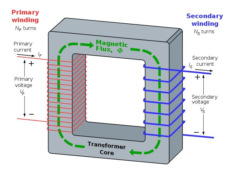
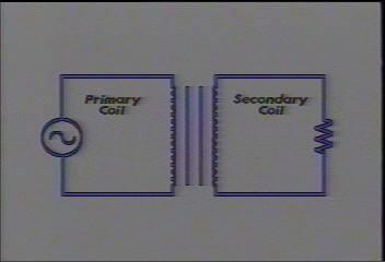
84 Turn Ratio: The number of turns of the primary compared to the number of turns of the secondary

85 Step Up 1: Step Down
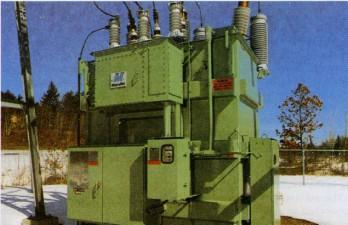
86 Distribution transformers 10-10= A phase B phase = Neutral Distribution Transformers have a true neutral, (Grounded current conductor) That only carries the current that is not neutralized by the other current carrying conductor
87 20-10= Distribution Transformers have a true neutral (Grounded current conductor) That only carries the current that is not neutralized by the other current carrying conductor
88 10-20= Distribution Transformers have a true neutral (Grounded current conductor) That only carries the current that is not neutralized by the other current carrying conductor

89 4-12= Distribution Transformers have a true neutral (Grounded current conductor) That only carries the current that is not neutralized by the other current carrying conductor
90
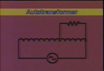
91 A special form of transformer having one winding, a portion of which is common to both the primary and the secondary circuits. The current in the high-voltage circuit flows through the series and common windings (see illustration). Typical autotransformer circuit. The current in the low-voltage circuit flows through the common winding and adds vectorially to the current in the high-voltage circuit to give the common winding current. Thus, an electrical connection exists between high-voltage and low-voltage windings. Because of this sharing of parts of the winding, an autotransformer having the same kilovolt-ampere (kva) output rating is generally smaller in weight and dimensions than a two-winding transformer. One possible disadvantage of auto-transformers is that the windings are not insulated from each other and that the autotransformer provides no isolation of the primary and secondary circuits. Autotransformers of large sizes are used for interconnecting high-voltage power systems. They are used in small sizes for intermittent-duty starting of motors. For this use the motor is connected for a short time to the common winding voltage, and then connected to the full line voltage. Small, variable-ratio autotransformers are used in testing and as components of other apparatus.


92 No load Current lags voltage by 90 deg. Current in the primary is 180 deg. out of phase with the secondary Voltage in the primary is 180 deg. out of phase with the secondary
93

94 No continuity continuity No continuity
95 Input and Output watts will be the same (minus the power factor)
96 Three-Phase Motors The magnetic field is concentrated between poles A1 and A2.

97 Three-Phase Motors The magnetic field is concentrated between poles of phases A and B.
98 Three-Phase Motors The magnetic field is concentrated between poles C1 and C2.
99 Three-Phase Motors The magnetic field is concentrated between poles C1 and C2.

100 Three-Phase Motors The magnetic field is concentrated between phases A and C.

101 Three-Phase Motors The magnetic field is concentrated between phases B and C.

102 Three-Phase Motors The magnetic field is concentrated between poles A1 and A2. The field has rotated 180.
103 Three-Phase Motors Synchronous Motors The operating speed and the speed of the rotating magnetic field (synchronous speed) are the same. It operates at constant speed from no load to full load. This motor can be used for power factor correction.
104 Three-Phase Motors Synchronous Motors A set of squirrel-cage bars known as the amortisseur winding are used to start the synchronous motor. A synchronous motor must never be started with DC current connected to the rotor. A field-discharge resistor is used to safely control excessive current and voltage.

105 Three-Phase Motors The field-discharge resistor is connected in parallel with the rotor winding during starting.
106 Motors BEFORE RE-SETTING TRIPPED OVERLOADS AND TRYING THE MOTOR AGAIN, YOU SHOULD ALWAYS: INSPECT THE MOTOR AND LOAD FOR OBVIOUS PROBLEMS
107 Motors WHICH DEVICES PREVENT MOTORS FROM DRAWING TOO MUCH CURRENT OVERLOADS
108 Motors WHICH OF THE FOLLOWING DEVICES WOULD NOT USE A MOTOR SPEED CONTROL? BLENDER SEWING MACHINES ELECTRIC DRILLS CLOCKS/TIMERS CLOCKS AND TIMERS
109 MOTORS COMBINATION STARTERS ARE DESIGNED TO HAVE THE DISCONNECT AND THE MOTOR STARTER INCLUDED IN: A SINGLE ENCLOSURE
110 MOTORS IN A PROCESS CONTROL, THE TIME IT TAKES FOR A CHANGE IN THE PROCESS TO BE FELT AT THE MEASURING DEVICE IS CALLED: DELAY
111 MOTOR A DEVICE USED TO MEASURE THE ROTATING SPEED OF A MOTOR IS CALLED A: TACHOMETER
112 MOTORS REVERSING CIRCUITS RUN THE MOTOR IN REVERSE BY SWAPPING THE POWER LEADS: TRUE
113 MOTOR THE IS THE DIFFERENCE BETWEEN THE SYNCHRONOUS SPEED AND THE ACTUAL ROTOR OR THE ACTUAL MOTOR SPEED: SLIP
114 MOTOR IF YOU WERE TO INCREASED THE FREQUENCY APPLIED TO AN INDUCTION MOTOR STARTER, THE ROTOR SPEED WOULD? INCREASE
115 Motors THE ACTUAL FULL LOAD AMPS OF A MOTOR ARE FOUND: NAME OF PLATE OF THE MOTOR

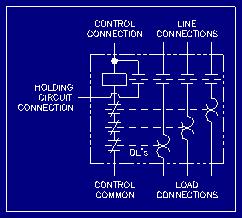
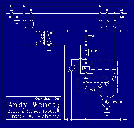
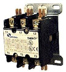
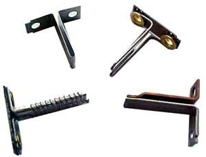
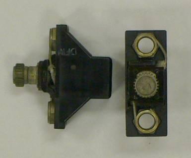
116 Motor Starters and Relays
117
118
119
120
121
122
123
124
125
126
127
128 Three-Phase Alternators Construction Alternators use the same operating principle as direct-current generators. However, alternators have no commutator to change the armature AC into DC. Most alternators are three-phase.

129 Three-Phase Alternators Basic design of a three-phase armature.
130 Three-Phase Alternators Construction There are two basic types of alternators: Revolving-armature-type alternators Revolving-field-type alternators

131 Three-Phase Alternators Revolving armature design.

132 Three-Phase Alternators Revolving field design.
133 Three-Phase Alternators Rotor The rotor is the rotating part of an alternator. The rotor is an electromagnet that provides the magnetic field needed to induce a voltage into the stator windings. Excitation current (DC) in the rotor is required to establish the magnetic field.

134 Three-Phase Alternators The alternator produces three sine wave voltages 120 out of phase with each other.

135 Three-Phase Alternators Rotator pole pieces become electromagnets.

136
137 Thank you
Unit 3 Magnetism...21 Introduction The Natural Magnet Magnetic Polarities Magnetic Compass...21
 Chapter 1 Electrical Fundamentals Unit 1 Matter...3 Introduction...3 1.1 Matter...3 1.2 Atomic Theory...3 1.3 Law of Electrical Charges...4 1.4 Law of Atomic Charges...4 Negative Atomic Charge...4 Positive
Preface...x Chapter 1 Electrical Fundamentals
 Preface...x Chapter 1 Electrical Fundamentals Unit 1 Matter...3 Introduction...3 1.1 Matter...3 1.2 Atomic Theory...3 1.3 Law of Electrical Charges...4 1.4 Law of Atomic Charges...5 Negative Atomic Charge...5
SECTION 3 BASIC AUTOMATIC CONTROLS UNIT 12 BASIC ELECTRICITY AND MAGNETISM. Unit Objectives. Unit Objectives 2/29/2012
 SECTION 3 BASIC AUTOMATIC CONTROLS UNIT 12 BASIC ELECTRICITY AND MAGNETISM Unit Objectives Describe the structure of an atom. Identify atoms with a positive charge and atoms with a negative charge. Explain
ECET 211 Electrical Machines and Controls
 ECET 211 Electrical Machines and Controls 2016/4/27 Class Review and Wrapping Up Comprehensive Exam, Friday, 1:00-3:00 PM, May 6, 2016 Close books/allow 1-page (8 x 11 and ½) hand-written review note,
Single-Phase Transformation Review
 Single-Phase Transformation Review S T U D E N T M A N U A L March 2, 2005 2 STUDENT TRAINING MANUAL Prerequisites: None Objectives: Given the Construction Standards manual and a formula sheet, you will
Table of Contents. Introduction...2 Conductors and Insulators...3 Current, Voltage, and Resistance...6
 Table of Contents Introduction...2 Conductors and Insulators...3 Current, Voltage, and Resistance...6 Ohm s Law... 11 DC Circuits... 13 Magnetism...20 Alternating Current...23 Inductance and Capacitance...30
TRANSFORMERS INTRODUCTION
 Tyco Electronics Corporation Crompton Instruments 1610 Cobb International Parkway, Unit #4 Kennesaw, GA 30152 Tel. 770-425-8903 Fax. 770-423-7194 TRANSFORMERS INTRODUCTION A transformer is a device that
Inductance, capacitance and resistance
 Inductance, capacitance and resistance As previously discussed inductors and capacitors create loads on a circuit. This is called reactance. It varies depending on current and frequency. At no frequency,
Placement Paper For Electrical
 Placement Paper For Electrical Q.1 The two windings of a transformer is (A) conductively linked. (B) inductively linked. (C) not linked at all. (D) electrically linked. Ans : B Q.2 A salient pole synchronous
MAHARASHTRA STATE BOARD OF TECHNICAL EDUCATION
 Important Instructions to examiners: 1) The answers should be examined by key words and not as word-to-word as given in the model answer scheme. 2) The model answer and the answer written by candidate
Introduction. Upon completion of Basics of Electricity you will be able to: Explain the difference between conductors and insulators
 Table of Contents Introduction...2 Electron Theory...4 Conductors, Insulators and Semiconductors...5 Electric Charges...7 Current...9 Voltage... 11 Resistance... 13 Simple Electric Circuit... 15 Ohm s
Basics of Electricity
 Basics of Electricity A quickstep Online Course Siemens industry, Inc. www.usa.siemens.com/step Trademarks Siemens is a trademark of Siemens AG. Product names mentioned may be trademarks or registered
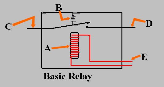
3/4/2015. Basic relay construction. Shading coil in AC relays. Timothy L. Skvarenina and William E. DeWitt Electrical Power and Controls, 2e
 FIGURE 12-1 Basic relay construction. FIGURE 12-2 Shading coil in AC relays. 1 FIGURE 12-3 Contactor coil and shaded pole stators. FIGURE 12-4 Magnetic motor starter. 2 FIGURE 12-5 Thermal overload devices.
CHAPTER 5 CONCEPTS OF ALTERNATING CURRENT
 CHAPTER 5 CONCEPTS OF ALTERNATING CURRENT INTRODUCTION Thus far this text has dealt with direct current (DC); that is, current that does not change direction. However, a coil rotating in a magnetic field
A Practical Guide to Free Energy Devices
 A Practical Guide to Free Energy Devices Device Patent No 30: Last updated: 24th June 2007 Author: Patrick J. Kelly This patent shows a method of altering a standard electrical generator intended to be
Basic Electrical Principles for Self Winding Clocks
 Basic Electrical Principles for Self Winding Clocks Ken Reindel NAWCC Chapter 15 1 Objective To de-mystify electrical principles Enrich Understanding Technical How self-winding technology came into being
1. Explain in detail the constructional details and working of DC motor.
 DHANALAKSHMI SRINIVASAN INSTITUTE OF RESEARCH AND TECHNOLOGY, PERAMBALUR DEPT OF ECE EC6352-ELECTRICAL ENGINEERING AND INSTRUMENTATION UNIT 1 PART B 1. Explain in detail the constructional details and
Reyrolle Protection Devices. 7PG11-18 Alpha Electromechanical Relays. Siemens. Answers for energy.
 Reyrolle Protection Devices 7PG11-18 Alpha Electromechanical Relays Answers for energy. Siemens Alpha Technical Manual Contents Contents Technical Manual Chapters 1. Introduction to Electromechanical
Module 1. Introduction. Version 2 EE IIT, Kharagpur
 Module 1 Introduction Lesson 1 Introducing the Course on Basic Electrical Contents 1 Introducing the course (Lesson-1) 4 Introduction... 4 Module-1 Introduction... 4 Module-2 D.C. circuits.. 4 Module-3
Team 2228 CougarTech 1. Training L1. Electric Circuits
 Team 2228 CougarTech 1 Training L1 Electric Circuits Team 2228 CougarTech 2 Objectives Understand: Understand the electrical Language Understand the basic components of electric circuits Understand ohms
TRANSFORMER OPERATION
 Chapter 3 TRANSFORMER OPERATION 1 A transformer is a static device (no moving parts) used to transfer energy from one AC circuit to another. This transfer of energy may involve an increase or decrease
Type KLF Generator Field Protection-Loss of Field Relay
 Supersedes DB 41-745B pages 1-4, dated June, 1989 Mailed to: E, D, C/41-700A ABB Power T&D Company Inc. Relay Division Coral Springs, FL Allentown, PA For Use With Delta Connected Potential Transformers
Trade of Electrician. The Transformer
 Trade of Electrician Standards Based Apprenticeship The Transformer Phase 2 Module No. 2.1 Unit No. 2.1.10 COURSE NOTES Created by Gerry Ryan - Galway TC Revision 1 April 2000 by Gerry Ryan - Galway TC
charge time Electric Current and Circuits Current HEAT will flow if there is a difference in temperature
 Electric Current and Circuits Electrons will flow if there is a difference in electric pressure. Electric pressure is called Potential, and is measured in Volts. If there is no difference in pressure from
END-OF-SUBCOURSE EXAMINATION
 END-OF-SUBCOURSE EXAMINATION Circle the letter of the correct answer to each question. When you have answered all of the questions, use a Number 2 pencil to transfer your answers to the TSC Form 59. 1.
~=E.i!=h. Pre-certification Transformers
 7 Transformers Section 26 of the electrical code governs the use and installations of transformers. A transformer is a static device used to transfer energy from one alternating current circuit to another.
Contents. Acknowledgments. About the Author
 Contents Figures Tables Preface xi vii xiii Acknowledgments About the Author xv xvii Chapter 1. Basic Mathematics 1 Addition 1 Subtraction 2 Multiplication 2 Division 3 Exponents 3 Equations 5 Subscripts
Electrical Machines (EE-343) For TE (ELECTRICAL)
 For TE (ELECTRICAL)") PRACTICALWORKBOOK Electrical Machines (EE-343) For TE (ELECTRICAL) Name: Roll Number: Year: Batch: Section: Semester: Department: N.E.D University of Engineering &Technology, Karachi Electrical Machines
PRACTICALWORKBOOK Electrical Machines (EE-343) For TE (ELECTRICAL) Name: Roll Number: Year: Batch: Section: Semester: Department: N.E.D University of Engineering &Technology, Karachi Electrical Machines
UNIT II MEASUREMENT OF POWER & ENERGY
 UNIT II MEASUREMENT OF POWER & ENERGY Dynamometer type wattmeter works on a very simple principle which is stated as "when any current carrying conductor is placed inside a magnetic field, it experiences
Hours / 100 Marks Seat No.
 17404 21314 3 Hours / 100 Seat No. Instructions (1) All Questions are Compulsory. (2) Answer each next main Question on a new page. (3) Illustrate your answers with neat sketches wherever necessary. (4)
Exercise 9. Electromagnetism and Inductors EXERCISE OBJECTIVE DISCUSSION OUTLINE DISCUSSION. Magnetism, magnets, and magnetic field
 Exercise 9 Electromagnetism and Inductors EXERCISE OBJECTIVE When you have completed this exercise, you will be familiar with the concepts of magnetism, magnets, and magnetic field, as well as electromagnetism
4. The circuit in an appliance is 3A and the voltage difference is 120V. How much power is being supplied to the appliance?
 1 Name: Date: / / Period: Formulas I = V/R P = I V E = P t 1. A circuit has a resistance of 4Ω. What voltage difference will cause a current of 1.4A to flow in the 2. How many amperes of current will flow
 VIDYARTHIPLUS - ANNA UNIVERSITY ONLINE STUDENTS COMMUNITY UNIT 1 DC MACHINES PART A 1. State Faraday s law of Electro magnetic induction and Lenz law. 2. Mention the following functions in DC Machine (i)
Industrial Electrician Level 3
 Industrial Electrician Level 3 Industrial Electrician Unit: C1 Industrial Electrical Code I Level: Three Duration: 77 hours Theory: Practical: 77 hours 0 hours Overview: This unit is designed to provide
Review 6. unlike poles cause the magnets to attract. like poles cause the magnets to repel.
 Review 6 1. The two characteristics of all magnets are: they attract and hold Iron, and, if free to move, they will assume roughly a south - north position. 2. Lines of flux always leave the north pole
VCE VET ELECTROTECHNOLOGY
 Victorian Certificate of Education 2010 SUPERVISOR TO ATTACH PROCESSING LABEL HERE STUDENT NUMBER Letter Figures Words VCE VET ELECTROTECHNOLOGY Written examination Thursday 4 November 2010 Reading time:
Generator Advanced Concepts
 Generator Advanced Concepts Common Topics, The Practical Side Machine Output Voltage Equation Pitch Harmonics Circulating Currents when Paralleling Reactances and Time Constants Three Generator Curves
Back to the Basics Current Transformer (CT) Testing
 Testing") Back to the Basics Current Transformer (CT) Testing As test equipment becomes more sophisticated with better features and accuracy, we risk turning our field personnel into test set operators instead of
Back to the Basics Current Transformer (CT) Testing As test equipment becomes more sophisticated with better features and accuracy, we risk turning our field personnel into test set operators instead of
REQUIRED SKILLS AND KNOWLEDGE UEENEEG101A. Electromagnetic devices and circuits. Topic and Description NIDA Lesson CARD # Magnetism encompassing:
 REQUIRED SKILLS AND KNOWLEDGE UEENEEG101A KS01-EG101A Electromagnetic devices and circuits T1 Magnetism encompassing: Topic and Description NIDA Lesson CARD # magnetic field pattern of bar and horse-shoe
Electrical Engineering / Electromagnetics
 Electrical Engineering / Electromagnetics. Plot voltage versus time and current versus time for the circuit with the following substitutions: A. esistor B. Capacitor C. Inductor t = 0 A/B/C A. I t t B.
3. What is hysteresis loss? Also mention a method to minimize the loss. (N-11, N-12)
") DHANALAKSHMI COLLEGE OF ENGINEERING, CHENNAI DEPARTMENT OF ELECTRICAL AND ELECTRONICS ENGINEERING EE 6401 ELECTRICAL MACHINES I UNIT I : MAGNETIC CIRCUITS AND MAGNETIC MATERIALS Part A (2 Marks) 1. List
DHANALAKSHMI COLLEGE OF ENGINEERING, CHENNAI DEPARTMENT OF ELECTRICAL AND ELECTRONICS ENGINEERING EE 6401 ELECTRICAL MACHINES I UNIT I : MAGNETIC CIRCUITS AND MAGNETIC MATERIALS Part A (2 Marks) 1. List
A Practical Guide to Free Energy Devices
 A Practical Guide to Free Energy Devices Part PatD14: Last updated: 25th February 2006 Author: Patrick J. Kelly This patent application shows the details of a device which it is claimed, can produce sufficient
DISCUSSION OF FUNDAMENTALS
 Unit 4 AC s UNIT OBJECTIVE After completing this unit, you will be able to demonstrate and explain the operation of ac induction motors using the Squirrel-Cage module and the Capacitor-Start Motor module.
CHIEF ENGINEER REG III/2 MARINE ELECTROTECHNOLOGY
 CHIEF ENGINEER REG III/2 MARINE ELECTROTECHNOLOGY LIST OF TOPICS 1 Electric Circuit Principles 2 Electronic Circuit Principles 3 Generation 4 Distribution 5 Utilisation The expected learning outcome is
Practical Tricks with Transformers. Larry Weinstein K0NA
 Practical Tricks with Transformers Larry Weinstein K0NA Practical Tricks with Transformers Quick review of inductance and magnetics Switching inductive loads How many voltages can we get out of a $10 Home
Basic Electrical Training
 Basic Electrical Training Electricians Tools Explain how various hand tools are used by an electrician Discuss the safe use of hand tools and power tools Perform basic calculations and measurement conversions
+ 24V 3.3K - 1.5M. figure 01
 ELECTRICITY ASSESSMENT 35 questions Revised: 08 Jul 2013 1. Which of the wire sizes listed below results in the least voltage drop in a circuit carrying 10 amps: a. 16 AWG b. 14 AWG c. 18 AWG d. 250 kcmil
Power systems Protection course
 Al-Balqa Applied University Power systems Protection course Department of Electrical Energy Engineering 1 Part 5 Relays 2 3 Relay Is a device which receive a signal from the power system thought CT and
Three-Phase Induction Motors. By Sintayehu Challa ECEg332:-Electrical Machine I
 Three-Phase Induction Motors 1 2 3 Classification of AC Machines 1. According to the type of current Single Phase and Three phase 2. According to Speed Constant Speed, Variable Speed and Adjustable Speed
ELECTROMAGNETIC INDUCTION AND ALTERNATING CURRENT (Assignment)
") ELECTROMAGNETIC INDUCTION AND ALTERNATING CURRENT (Assignment) 1. In an A.C. circuit A ; the current leads the voltage by 30 0 and in circuit B, the current lags behind the voltage by 30 0. What is the
ELECTROMAGNETIC INDUCTION AND ALTERNATING CURRENT (Assignment) 1. In an A.C. circuit A ; the current leads the voltage by 30 0 and in circuit B, the current lags behind the voltage by 30 0. What is the
Electrical Theory. Power Principles and Phase Angle. PJM State & Member Training Dept. PJM /22/2018
 Electrical Theory Power Principles and Phase Angle PJM State & Member Training Dept. PJM 2018 Objectives At the end of this presentation the learner will be able to: Identify the characteristics of Sine
Introduction : Design detailed: DC Machines Calculation of Armature main Dimensions and flux for pole. Design of Armature Winding & Core.
 Introduction : Design detailed: DC Machines Calculation of Armature main Dimensions and flux for pole. Design of Armature Winding & Core. Design of Shunt Field & Series Field Windings. Design detailed:
Power. Power is the rate of using energy in joules per second 1 joule per second Is 1 Watt
 3 phase Power All we need electricity for is as a source of transport for energy. We can connect to a battery, which is a source of stored energy. Or we can plug into and electric socket at home or in
FINAL - ET 60 - Electrician Theory Examination Marking Schedule
 FINAL - ET 60 - Electrician Theory Examination Marking Schedule Notes:1. means that the preceding statement/answer earns 1 mark. 2. This schedule sets out the accepted answers to the examination questions.
VALLIAMMAI ENGINEERING COLLEGE
 VALLIAMMAI ENGINEERING COLLEGE SRM Nagar, Kattankulathur 603 203 DEPARTMENT OF ELECTRONICS AND INSTRUMENTATION ENGINEERING QUESTION BANK IV SEMESTER EI6402 ELECTRICAL MACHINES Regulation 2013 Academic
TRANSFORMER THEORY. Mutual Induction
 Transformers Transformers are used extensively for AC power transmissions and for various control and indication circuits. Knowledge of the basic theory of how these components operate is necessary to
Voltage-Versus-Speed Characteristic of a Wind Turbine Generator
 Exercise 1 Voltage-Versus-Speed Characteristic of a Wind Turbine Generator EXERCISE OBJECTIVE When you have completed this exercise, you will be familiar with the principle of electromagnetic induction.
Table of Contents. Table of Figures. Table of Tables
 Abstract The aim of this report is to investigate and test a transformer and check if it is good to use by doing the following tests continuity test, insulation test, polarity test, open circuit test,
INSTITUTE OF AERONAUTICAL ENGINEERING (AUTONOMOUS) Dundigal, Hyderabad
 Dundigal, Hyderabad") INSTITUTE OF AERONAUTICAL ENGINEERING (AUTONOMOUS) Dundigal, Hyderabad - 500 043 CIVIL ENGINEERING ASSIGNMENT Name : Electrical and Electronics Engineering Code : A30203 Class : II B. Tech I Semester Branch
INSTITUTE OF AERONAUTICAL ENGINEERING (AUTONOMOUS) Dundigal, Hyderabad - 500 043 CIVIL ENGINEERING ASSIGNMENT Name : Electrical and Electronics Engineering Code : A30203 Class : II B. Tech I Semester Branch
ELECTRIC CURRENTS AND CIRCUITS By: Richard D. Beard P.E.
 ELECTRICAL POWER There are two types of electric power in use, direct current (dc) and alternating current (ac). The most common use of direct current is automotive, including storage batteries, starter
The topics in this unit are:
 The topics in this unit are: 1 Static electricity 2 Repulsion and attraction 3 Electric circuits 4 Circuit symbols 5 Currents 6 Resistance 7 Thermistors and light dependent resistors 8 Series circuits
NATIONAL CERTIFICATE (VOCATIONAL) ELECTRICAL PRINCIPLES AND PRACTICE NQF LEVEL 4 NOVEMBER 2009
 ELECTRICAL PRINCIPLES AND PRACTICE NQF LEVEL 4 NOVEMBER 2009") NATIONAL CERTIFICATE (VOCATIONAL) ELECTRICAL PRINCIPLES AND PRACTICE NQF LEVEL 4 NOVEMBER 2009 (12041004) 23 November (X-Paper) 09:00 12:00 Calculators may be used. This question paper consists of 7 pages.
NATIONAL CERTIFICATE (VOCATIONAL) ELECTRICAL PRINCIPLES AND PRACTICE NQF LEVEL 4 NOVEMBER 2009 (12041004) 23 November (X-Paper) 09:00 12:00 Calculators may be used. This question paper consists of 7 pages.
Figure 1. Why is iron a suitable material for the core of a transformer?
 INDUCED POTENTIAL, TRANSFORMERS: NAT GRID Q1. Figure 1 shows the construction of a simple transformer. Figure 1 Why is iron a suitable material for the core of a transformer? Tick one box. It is a metal.
Construction Electrician/Industrial Electrician/Power Electrician Common Core Level 2
 Common Core Level 2 Unit: B1 Commercial Electrical Code Level: Two Duration: 60 hours Theory: Practical: 60 hours 0 hours Overview: This unit is designed to provide the apprentice with the knowledge about
3.1.Introduction. Synchronous Machines
 3.1.Introduction Synchronous Machines A synchronous machine is an ac rotating machine whose speed under steady state condition is proportional to the frequency of the current in its armature. The magnetic
Conceptual Physics Fundamentals
 Conceptual Physics Fundamentals Chapter 11: MAGNETISM AND ELECTROMAGNET INDUCTION This lecture will help you understand: Magnetic Poles Magnetic Fields Magnetic Domains Electric Currents and Magnetic Fields
Deploying Current Transformers in Applications Greater Than 200 A
 Deploying Current Transformers in Applications Greater Than 200 A Andrew Schaeffler Step-down Current Transformers (CTs) are common, and useful, in large motor applications. They provide isolation between
1. (a) Determine the value of Resistance R and current in each branch when the total current taken by the curcuit in figure 1a is 6 Amps.
 Determine the value of Resistance R and current in each branch when the total current taken by the curcuit in figure 1a is 6 Amps.") Code No: 07A3EC01 Set No. 1 II B.Tech I Semester Regular Examinations, November 2008 ELECTRICAL AND ELECTRONICS ENGINEERING ( Common to Civil Engineering, Mechanical Engineering, Mechatronics, Production
Code No: 07A3EC01 Set No. 1 II B.Tech I Semester Regular Examinations, November 2008 ELECTRICAL AND ELECTRONICS ENGINEERING ( Common to Civil Engineering, Mechanical Engineering, Mechatronics, Production
FCC Technician License Course
 FCC Technician License Course 2014-2018 FCC Element 2 Technician Class Question Pool Presented by: Tamiami Amateur Radio Club (TARC) WELCOME To the SECOND of 4, 3-hour classes presented by TARC to prepare
Glossary of Common Magnetic Terms
 Glossary of Common Magnetic Terms Copyright by Magnelab, Inc. 2009 Air Core A term used when no ferromagnetic core is used to obtain the required magnetic characteristics of a given coil. (see Core) Ampere
Radio and Electronics Fundamentals
 Amateur Radio License Class Radio and Electronics Fundamentals Presented by Steve Gallafent September 26, 2007 Radio and Electronics Fundamentals Voltage, Current, and Resistance Electric current is the
SHRI RAMSWAROOP MEMORIAL COLLEGE OF ENGG. & MANAGEMENT
 SHRI RAMSWAROOP MEMORIAL COLLEGE OF ENGG. & MANAGEMENT B.Tech. [SEM I (CE,EC,EE,EN)] QUIZ TEST-3 (Session: 2012-13) Time: 1 Hour ELECTRICAL ENGINEERING Max. Marks: 30 (EEE-101) Roll No. Academic/26 Refer/WI/ACAD/18
Chapter 24. Alternating Current Circuits
 Chapter 24 Alternating Current Circuits Objective of Lecture Generators and Motors Inductance RL Circuits (resistance and inductance) Transformers AC REMINDER: WORK ON THE EXAMPLES Read physics in perspective
OD1647 ELECTRONIC PRINCIPLES
 SUBCOURSE OD1647 EDITION 8 ELECTRONIC PRINCIPLES ELECTRONIC PRINCIPLES SUBCOURSE OD1647 EDITION 8 United States Army Combined Arms Support Command Fort Lee, VA 23801 1809 7 Credit Hours NEW: 1988 GENERAL
UEE11 Electrotechnology. Training Package
 UEE11 Electrotechnology Training Package UEENEEJ153A Find and rectify faults in motors and associated controls in refrigeration and air conditioning systems Learner Workbook Version 1 Training and Education
Electromechanical Technology /Electromechanical Engineering Technology CIP Task Grid
 1 Secondary Task List 100 DEMONSTRATE KNOWLEDGE OF TECHNICAL REPORTS 101 Identify components of technical reports. 102 Demonstrate knowledge of the common components of technical documents. 103 Maintain
INSTITUTE OF AERONAUTICAL ENGINEERING Dundigal, Hyderabad
 Course Name Course Code Class Branch INSTITUTE OF AERONAUTICAL ENGINEERING Dundigal, Hyderabad -500 043 AERONAUTICAL ENGINEERING TUTORIAL QUESTION BANK : ELECTRICAL AND ELECTRONICS ENGINEERING : A40203
Dhanalakshmi Srinivasan Institute of Technology, Samayapuram, Trichy. Cycle 2 EE6512 Electrical Machines II Lab Manual
 Cycle 2 EE652 Electrical Machines II Lab Manual CIRCUIT DIAGRAM FOR SLIP TEST 80V DC SUPPLY 350Ω, 2 A 3 Point Starter L F A NAME PLATE DETAILS: 3Ф alternator DC shunt motor FUSE RATING: Volts: Volts: 25%
Radio Teacher Technician Test Subelement T4 Notes
 Radio Teacher Technician Test These notes cover the information needed to answer the questions on Subelement T4 of the Amateur Radio Technician Test. They can be used by instructors as a reference to make
CHAPTER 8: ELECTROMAGNETISM
 CHAPTER 8: ELECTROMAGNETISM 8.1: MAGNETIC EFFECT OF A CURRENT-CARRYING CONDUCTOR Electromagnets 1. Conductor is a material that can flow.. 2. Electromagnetism is the study of the relationship between.and..
Electrical Functions Notes
 Electrical Functions Notes Electrical Function An electrical function is the role that a component plays in the control or transformation of electric current. Power Supplies Power supply is the electrical
Power Electrician Level 3
 s Power Electrician Level 3 Rev. September 2008 Power Electrician Unit: C1 Electrical Code III Level: Three Duration: 60 hours Theory: Practical: 60 hours 0 hours Overview: This unit of instruction is
Prof. Hala J. El Khozondar Spring 2016
 Technical English Unit 43 professional english Current, voltage and resistance Prof. Hala J. El Khozondar Spring 2016 Content A. Electric current B. Voltage and resistance C. Electrical power 2 A. Electric
Electrical Components and their Functions
 Electrical Components and their Functions Electricity & Electronics All electrical appliances and electronic devices depend on electrical circuits. The main difference between electricity & electronics
Units 1,2,3,9,12 Delmars Standard Textbook of Electricity
 Units 1,2,3,9,12 Delmars Standard Textbook of Electricity 1. What are the two basic types of electric sources? 2. What is the effect of unlike charges on each other? 3. What is the effect of like charges
In an unmagnetized piece of iron, the atoms are arranged in domains. In each domain the atoms are aligned, but the domains themselves are random.
 4/7 Properties of the Magnetic Force 1. Perpendicular to the field and velocity. 2. If the velocity and field are parallel, the force is zero. 3. Roughly (field and vel perp), the force is the product
Alternating Current Study Guide. Preface. This module is DIFFICULT.
 Preface This module is DIFFICULT. This material will take more effort to understand and more effort to pass than tests from previous modules. This is on par with a college-level electrical engineering
Units 1,2,3,9,12 Delmars Standard Textbook of Electricity
 Units 1,2,3,9,12 Delmars Standard Textbook of Electricity 1. What are the two basic types of electric sources? Alternating and Direct Current 2. What is the effect of unlike charges on each other? Attract
Construction Electrician Level 2
 Level 2 Rev. September 2008 Unit: B1 Electrical Code II Level: Two Duration: 120 hours Theory: Practical: 99 hours 21 hours Overview: This unit of instruction is designed to provide the Electrician apprentice
INSTITUTE OF AERONAUTICAL ENGINEERING (AUTONOMOUS)
") Name Code Class Branch INSTITUTE OF AERONAUTICAL ENGINEERING (AUTONOMOUS) Dundigal, Hyderabad -500 043 CIVIL ENGINEERING TUTORIAL QUESTION BANK : ELECTRICAL AND ELECTRONICS ENGINEERING : A30203 : II B.
Name Code Class Branch INSTITUTE OF AERONAUTICAL ENGINEERING (AUTONOMOUS) Dundigal, Hyderabad -500 043 CIVIL ENGINEERING TUTORIAL QUESTION BANK : ELECTRICAL AND ELECTRONICS ENGINEERING : A30203 : II B.
PART A. 1. List the types of DC Motors. Give any difference between them. BTL 1 Remembering
 UNIT I DC MACHINES Three phase circuits, a review. Construction of DC machines Theory of operation of DC generators Characteristics of DC generators Operating principle of DC motors Types of DC motors
Electric Circuits. Alternate Units. V volt (V) 1 V = 1 J/C V = E P /q V = W/q. Current I ampere (A) 1 A = 1 C/s V = IR I = Δq/Δt
 1 V = 1 J/C V = E P /q V = W/q. Current I ampere (A) 1 A = 1 C/s V = IR I = Δq/Δt") Electric Circuits Quantity Symbol Units Charge Q,q coulomb (C) Alternate Units Formula Electric Potential V volt (V) 1 V = 1 J/C V = E P /q V = W/q Work, energy W, E P joule (J) W = qv E P = qv Current
Electric Circuits Quantity Symbol Units Charge Q,q coulomb (C) Alternate Units Formula Electric Potential V volt (V) 1 V = 1 J/C V = E P /q V = W/q Work, energy W, E P joule (J) W = qv E P = qv Current
ELEXBO. Electrical - Experimentation Box
 ELEXBO Electrical - Experimentation Box 1 Table of contents 2 Introduction...3 Basics...3 The current......4 The voltage...6 The resistance....9 Measuring resistance...10 Summary of the electrical values...11
Walchand Institute of Technology. Basic Electrical and Electronics Engineering. Transformer
 Walchand Institute of Technology Basic Electrical and Electronics Engineering Transformer 1. What is transformer? explain working principle of transformer. Electrical power transformer is a static device
GRAAD 12 NATIONAL SENIOR CERTIFICATE GRADE 12
 GRAAD 12 NATIONAL SENIOR CERTIFICATE GRADE 12 ELECTRICAL TECHNOLOGY EXEMPLAR 2014 MEMORANDUM MARKS: 200 This memorandum consists of 13 pages. Electrical Technology 2 DBE/2014 INSTRUCTIONS TO THE MARKERS
Electronic Speed Controls and RC Motors
 Electronic Speed Controls and RC Motors ESC Power Control Modern electronic speed controls regulate the electric power applied to an electric motor by rapidly switching the power on and off using power
Introduction. Inductors in AC Circuits.
 Module 3 AC Theory What you ll learn in Module 3. Section 3.1 Electromagnetic Induction. Magnetic Fields around Conductors. The Solenoid. Section 3.2 Inductance & Back e.m.f. The Unit of Inductance. Factors
Any path along which electrons can flow is a circuit A Battery and a Bulb
 Any path along which electrons can flow is a circuit. Mechanical things seem to be easier to figure out for most people than electrical things. Maybe this is because most people have had experience playing
PHYS 1442 Section 004 Lecture #15
 PHYS 1442 Section 004 Lecture #15 Monday March 17, 2014 Dr. Andrew Brandt Chapter 21 Generator Transformer Inductance 3/17/2014 1 PHYS 1442-004, Dr. Andrew Brandt Announcements HW8 on Ch 21-22 will be
Electrical Theory 2 Lessons for Fall Semester:
 Electrical Theory 2 Lessons for Fall Semester: Lesson 1 Magnetism Lesson 2 Introduction to AC Theory Lesson 3 Lesson 4 Capacitance and Capacitive Reactance Lesson 5 Impedance and AC Circuits Lesson 6 AC