Basic Electrical Principles for Self Winding Clocks
|
|
|
- Paul Gibson
- 6 years ago
- Views:
Transcription
1 Basic Electrical Principles for Self Winding Clocks Ken Reindel NAWCC Chapter 15 1
2 Objective To de-mystify electrical principles Enrich Understanding Technical How self-winding technology came into being Offer solid technical foundation for working on Self-winding Clocks This is NOT a course on self winding clock repair (that one is next!) 2
3 Approach Start with Historical Perspective Explain simple mathematical relationships Apply them with a mini lab Discussion, answer questions 3
4 Agenda Historical Basic Electricity Ohm s Law Power Law Double the voltage, quadruple the trouble Components Resistors Batteries Coils and Electromagnets Contacts Making Basic Electrical Measurements Digital Multimeter Basics Mini-Lab 4

 saturated paper sandwiched in between disks of silver and zinc would produce an electrical potential")
5 The 1700s Benjamin Franklin, American inventor and politician. In 1752 he established that lightning and Static electricity were fundamentally the same. He also established the conventions of negatively charged electrons and positively charged protons. Alessandra Volta, Italian mathematician. In 1792 he proved that brine-(saltwater) saturated paper sandwiched in between disks of silver and zinc would produce an electrical potential (electrical pressure). This was the origin of the BATTERY! The unit of electrical potential or pressure was named in his honor. 5


6 Early 1800s Andre-Marie Ampere, French Mathematician. In 1826, he published the results of his studies that related electric current flow to magnetism (but gave credit for it to Michael Faraday). The unit of electrical current flow was named after him. George Ohm, German Physicist and mathematician. In 1827 he published "The Galvanic Circuit Investigated Mathematically, quantifying the relationships between electrical potential, electric current flow, and resistance. The unit of resistance was named after him. 6


7 Significant Advances Georges Leclanché, French Scientist and Engineer. In 1866 Leclanché developed the first practical 1.5 volt wet cell. Over 20,000 were produced to power telegraphs, clocks, doorbells. Was the forerunner of the Dry Battery (first realized by Carl Gassner and later E. M. Jewett) or modern carbon-zinc cell. Thomas Alva Edison, American Inventor: Between 1850 and well into the early 1900 s, Edison applied the theories of many predecessors to the invention or refinement of the incandescent light, DC motor, DC generator, and first practical storage battery. 7
8 The Atom Composed of: Protons Neutrons Electrons Protons and neutrons are tightly bound into a nucleus Electrons are relatively loosely held and can be moved in and out of atomic shells Electrons can be moved from atom to atom by electrical pressure Electrons can also be freed by chemical reactions, creating electrical pressure 8


9 Insulators and Conductors Insulators are materials that do not readily allow the electrons in their atoms to move freely from atom to atom. Examples are glass, wood, air. Conductors are materials that freely allow movement of electrons between the individual atoms. Metals are the primary example. 9
10 How Batteries Work A device for storing electrical pressure or potential Consists of 2 conducting plates and an electrolyte Negative (-) Positive (+) The electrolyte and a conductor react chemically, releasing an abundance of electrons Electrolyte This abundance of free electrons results in electrical pressure or potential, measured as voltage 10
11 Battery Connected Electron Flow (Amps) Load Negative (-) Electrical Potential Positive (+) (Volts) Electrolyte When an external path is connected, the electrons flow back towards the + terminal and create a chemical reaction at the anode. 11

12 The Leclanché Cell Earliest practical battery ( ) Forerunner of Dry Battery Patented; over 20,000 built Had a tendency to spill 1.5 volt cell 12

13 Gonda Leclanché Cells 13


14 Self Winding Clock Co. Wet Cell $180 on Ebay 14
15 The Columbia Battery National Carbon Co. of Lakewood, OH Founded in 1894 Originally manufactured Leclanché cells Decades later became Eveready and then Energizer E. M. Jewett and George Little Developed a zinc can-based cell in 1896 Used carbon as the center cathode (+) Acidic paste electrolyte with a cardboard separator Powered telephone, doorbells, automobiles (ignitor), self-winding clocks, lanterns, etc. Transformed the industry! 15

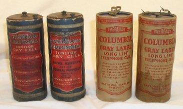
16 The Columbia Battery 16
 17")
17 Resistors Many electrical loads are resistive (at least partially) Motors, light bulbs, electromagnets, etc. Other examples of resistors: Resistors are measured in Ohms (Ω) 17

18 Wire Resistance Wire resistance varies by length and thickness Also depends on the type of wire e.g., copper or NiCr 18


19 SWCC Damping Resistors 19
20 Elements of Electricity Voltage Electrical Pressure or Potential Batteries are an example of a voltage source Current A measure of the FLOW of electricity Measured in Amps Resistance A measure of the restriction to FLOW Measured in Ohms 20
21 Elements of Electricity Electron Flow (Amps) Load (Ohms) - + Electrical Potential (Volts) Ohm s Law: Voltage = Amps x Ohms Also, Amps = Voltage/Ohms Battery Power (Watts) = Amps x Volts Power (Watts) = Volts 2 /Ohms Power is a measure of energy 21
22 Example Application of Ohm s Law Coil resistance = 6Ω Battery voltage = 3 volts + 3 V 6Ω coil How many amps will be needed from battery? Amps =? Answer: Amps = Volts/Ohms = 3 volts/ 6Ω = ½ Amp 22
23 Let s keep going.. For the same circuit: Power =?? How much power is dissipated in the coil? + 3 V 6Ω coil Answer: ½ Amp Power = Voltage 2 /Ohms = 3 2 volts/6ω = 1.5 watts 23
24 For the same circuit: One more time How much more power is dissipated in the coil if we use a Lantern battery which is 6 volts??? + 6 V Power =?? 6Ω coil Answer: 1 Amp Power = Voltage 2 /Ohms = 6 2 volts/6ω = 6 watts or 4x more!! 24
 forces 4x the energy into the electrical")
25 Lesson Learned.. Double the voltage (6V) forces 4x the energy into the electrical components DO NOT USE in 3V clocks Unless you use a voltage converter 25
26 Series Circuits Batteries in SERIES add: 1.5 volt 1.5 volt + + Clock motor sees 3 volts Clock Motor Resistors in SERIES also add: 6Ω 6Ω Total Resistance = 12Ω 26
27 Parallel Circuits Batteries in PARALLEL of same voltage will output that voltage, but increase Amperage capacity 1.5V 1.5V Clock motor sees 1.5 volts which may not be sufficient + + Clock Motor If each battery can supply 2 amps, two in parallel can supply 4 amps. 6Ω 6Ω N like value resistors in parallel reduce by: R p = R/N 6Ω// 6Ω = 3Ω 27

28 Coils and Electromagnets If a current is passed through a wire, a magnetic field results This magnetic field encircles the wire as shown. The magnetic field will form around magnetic materials if we let it 28


29 Coils and Electromagnets Winding multiple turns around a core will concentrate the magnetic field as shown. An example of a simple electromagnet can be made using enameled wire wrapped around a nail! All coils have some winding resistance resulting from the copper 29
 Example: If V =3 volts and R is 6 Ω, then: Coil with")
30 Challenges with Coils What happens when I energize this synchronizer coil? Current will flow through the coil Amps = V/(coil R) Example: If V =3 volts and R is 6 Ω, then: Coil with resistance R Amps =? V + Amps = 3V/6Ω = 0.5 Amp 30
31 Challenges with Coils What happens when we disconnect the coil? 1. Energy is stored in the coil as an electromagnetic field. That s the nature of a coil. 2. So, when the switch is opened, the current will want to keep flowing in the coil. 3. It will increase its voltage until the contact arcs over (100 s or 1000 s of volts). 4. The spot temperature from this arc is hot enough to melt metal, thus pitting and damaging the contacts. 3V Coil with resistance R 0.5 Amps -1000V V 0V Waveform at Contact 31 +
32 Challenges with Coils Question: How do I prevent this? Answer: Create somewhere else for the coil current to go when the contact opens. 3V 0V 60Ω Coil with resistance 6Ω V + -27V 0.5 Amps Flyback current 32
33 Challenges with Coils Most common option is a Damping resistor, usually selected to be 10x the value of the coil resistance. Another option is a diode, but this was obviously not used in vintage days. cathode Diode Coil with resistance 6Ω 0.5 Amps V + 3V -0.7V 0V Flyback current 33
34 Contacts What makes a good contact??? Largely depends on the application, but. Low contact resistance Resistant to oxidation And, therefore, burning Probably also means high melting temp Good hardness wears well over time 34
35 Contacts What kind of materials offer these qualities? Material Low Contact R Resistance to Surface Films Hardness (wears well) Gold Better Best Poor Platinum Better Best Better (especially Platinum-Iridium) Silver Best (initially) Fair Good Tungsten Good Good Best Copper Best (initially) Poor Poor 35
36 Contacts Platinum is the best pure material (non alloy) Platinum-iridium is great because of additional hardness Unfortunately both are VERY EXPENSIVE But they are WORTH IT! Clocks restored with platinum will run much longer 36


37 ACCT AR5GrWbv DeoxIT and DeoxIT Gold G100L Caig Laboratories Proven over 50 year history Unbelievable results Examples Only a very small quantity needed on CLEAN contacts to preserve them indefinitely Don t flood contact with it Possible lubricant for Style A motor bearings and commutators 37


38 Electric Motors Electromagnetism is exploited Opposite magnetic poles attract; like poles repel Rotation causes reversal of the electromagnetic field because of the commutator 38
 Multi Function Volts Ohms Amps Continuity Diode Test Accuracy ~1% Good enough for most if not all clock")
39 Basic Electrical Measurements The standard instrument for basic electrical measurements is the DMM (Digital MultiMeter) Multi Function Volts Ohms Amps Continuity Diode Test Accuracy ~1% Good enough for most if not all clock work 39
40 Important Aspects of DMM Measurements Know your DMM Make sure the range is appropriate for what you expect to measure!! Make sure the leads are in the right place Make practice measurements before doing anything real Make sure you have a good zero If you don t, subtract the offset from your measurement to obtain most accurate reading Especially true with low voltages 40
41 Experiment 1: Measure the resistance of devices Set DMM to 200 ohm range 1. Touch both probe tips to a terminal 2. Record offset 3. Measure device of interest eg Terminal 3 and Terminal 4 4. Subtract value in Step 2 from value in Step 3. 41
42 Experiment 2: Measuring Voltage Set DMM to 20 Volts DC range 1. Measure battery terminal voltage. 2. Now, connect battery to light bulb (Terminals 5 and 6). 3. Measure battery terminal voltage again. 4. Compare result from 2 to result from 4. 42
43 Experiment 3: Stall Current of Motor Connect a wire between Terminal 2 and Terminal 6 Connect battery (with test clips) between Terminal 1 and Terminal 5 Stop motor with fingers What happens??? Why??? 43
44 Experiment 4: Coil Arcing 1. Connect one of the battery leads to Terminal 3 using test clip. 2. Touch other test clip to Terminal 4 3. As you do, notice the spark. Why is there a spark there? 4. Now, connect Terminal 3 to Terminal 7 5. Likewise connect Terminal 4 to Terminal Repeat the test in 1-2 above. What happened? Why? 44
SECTION 3 BASIC AUTOMATIC CONTROLS UNIT 12 BASIC ELECTRICITY AND MAGNETISM. Unit Objectives. Unit Objectives 2/29/2012
 SECTION 3 BASIC AUTOMATIC CONTROLS UNIT 12 BASIC ELECTRICITY AND MAGNETISM Unit Objectives Describe the structure of an atom. Identify atoms with a positive charge and atoms with a negative charge. Explain
Team 2228 CougarTech 1. Training L1. Electric Circuits
 Team 2228 CougarTech 1 Training L1 Electric Circuits Team 2228 CougarTech 2 Objectives Understand: Understand the electrical Language Understand the basic components of electric circuits Understand ohms
The Discussion of this exercise covers the following points:
 Exercise 5 Resistance and Ohm s Law EXERCISE OBJECTIVE When you have completed this exercise, you will be familiar with the notion of resistance, and know how to measure this parameter using an ohmmeter.
Introduction. A closed loop of wire is not an electrical circuit, a circuit requires
 The Law of Charges Opposite charges attract like charges repel Lines of force can never cross each other The values are equal but the effect is opposite Strength of the attraction is exponential to its
ELEXBO. Electrical - Experimentation Box
 ELEXBO Electrical - Experimentation Box 1 Table of contents 2 Introduction...3 Basics...3 The current......4 The voltage...6 The resistance....9 Measuring resistance...10 Summary of the electrical values...11
Ampere describes the number of electrons that flow through a circuit in one second. It is named after Andre-Marie Ampere, who was one of the first
 Ampere describes the number of electrons that flow through a circuit in one second. It is named after Andre-Marie Ampere, who was one of the first people to use math to describe electricity. A battery
4. The circuit in an appliance is 3A and the voltage difference is 120V. How much power is being supplied to the appliance?
 1 Name: Date: / / Period: Formulas I = V/R P = I V E = P t 1. A circuit has a resistance of 4Ω. What voltage difference will cause a current of 1.4A to flow in the 2. How many amperes of current will flow
Born: March 16, 1789, Erlangen, Germany Died: July 6, 1854, Munich, Germany Education: University of Erlangen-Nuremberg
 Ohm s Law Georg Simon Ohm was a German physicist and mathematician. As a school teacher, Ohm began his research with the new electrochemical cell, invented by Italian scientist Alessandro Volta. Born:
Resistance. What is resistance? Vocabulary: resistance resistor electric current electric charge delocalised conductor
 Date: Resistance Key questions: What is resistance? What do we use resistors for? Does length affect resistance? Does temperature affect resistance? Does the type of resistor material affect resistance?
Basic Circuits. PC1222 Fundamentals of Physics II. 1 Objectives. 2 Equipment List. 3 Theory
 PC1222 Fundamentals of Physics II Basic Circuits 1 Objectives Investigate the relationship among three variables (resistance, current and voltage) in direct current circuits. Investigate the behaviours
Self-assessment practice test questions Block 4
 elf-assessment practice test questions Block 4 1 A student uses a bar magnet to magnetise an iron wire, as shown in the diagram. he strokes the N pole of the magnet along the length of the wire, and repeats
CURRENT ELECTRICITY. 1. The S.I. unit of power is (a) Henry (b) coulomb (c) watt (d) watt-hour Ans: c
 Henry (b) coulomb (c) watt (d) watt-hour Ans: c") CURRENT ELECTRICITY 1. The S.I. unit of power is (a) Henry (b) coulomb (c) watt (d) watt-hour 2. Electric pressure is also called (a) resistance (b) power (c) voltage (d) energy 3. The substances which
CURRENT ELECTRICITY 1. The S.I. unit of power is (a) Henry (b) coulomb (c) watt (d) watt-hour 2. Electric pressure is also called (a) resistance (b) power (c) voltage (d) energy 3. The substances which
ELECTRICITY. Now that s shocking!
 ELECTRICITY Now that s shocking! Electricity & Circuits Quantity Chart Quantity Variable in Formula Unit Unit s Symbol Charge q Coulombs C Potential Difference V Volts V Voltage V Volts V Current I Amps
Resistance and Ohm s Law R V I. 1 ohm = 1 volt ampere
 Resistance and Ohm s Law If you maintain an electric potential difference, or voltage V, across any conductor, an electric current occurs. In general, the magnitude of the current depends on the potential
Multimeter Definition
 Multimeter Definition A multimeter is a devise used to measure voltage, resistance and current in electronics & electrical equipment It is also used to test continuity between to 2 points to verify if
Radio Teacher Technician Test Subelement T4 Notes
 Radio Teacher Technician Test These notes cover the information needed to answer the questions on Subelement T4 of the Amateur Radio Technician Test. They can be used by instructors as a reference to make
Current Electricity. What is Current Electricity? Electrical Circuits Electrochemical Cells. Wet, Dry and Fuel Cells
 Current Electricity What is Current Electricity? Electrical Circuits Electrochemical Cells Wet, Dry and Fuel Cells Current Electricity Current Electricity continuous flow of electrons in a closed circuit
Task 1 - Building a Wet Cell
 The following instructional plan is part of a GaDOE collection of Unit Frameworks, Performance Tasks, examples of Student Work, and Teacher Commentary. Many more GaDOE approved instructional plans are
Electricity. Preparation. Objectives. Standards. Materials. Grade Level: 3-6 Group Size: Time: Minutes Presenters: 3-5
 Electricity Preparation Grade Level: 3-6 Group Size: 20-30 Time: 45-60 Minutes Presenters: 3-5 Objectives This lesson will enable students to: Observe and explain the effects of a magnetic field Build
Downloaded from
 Question 1: What does an electric circuit mean? An electric circuit consists of electric devices, switching devices, source of electricity, etc. that are connected by conducting wires. Question 2: Define
Units 1,2,3,9,12 Delmars Standard Textbook of Electricity
 Units 1,2,3,9,12 Delmars Standard Textbook of Electricity 1. What are the two basic types of electric sources? Alternating and Direct Current 2. What is the effect of unlike charges on each other? Attract
The Forefathers of Radio. By Bob Buus, W2OD
 The Forefathers of Radio By Bob Buus, W2OD Benjamin Franklin Jan. 17, 1706 April 17, 1790 (84) Born in Boston Apprentice Printer 1723 to Philadelphia 1723-26 in London Printing Business Retired in 1747
Circuits: Light-Up Creatures Teacher version
 Circuits: Light-Up Creatures Teacher version In this lab you will explore current, voltage and resistance and their relationships as given by the Ohm s law. You will also explore of how resistance can
Voltage, Current, and Resistance. Objectives
 Voltage, Current, and Resistance ELEC 111 Objectives Define voltage and discuss its characteristics Define current and discuss its characteristics Define resistance and discuss its characteristics 21 January
Block Diagram of a DC Power Supply. Wiring diagrams are used to help with the actual circuit wiring.
 Electronics Technology and Robotics I Week 3 Schematics, Conductors, and Insulators Administration: o Prayer o Review measuring voltage, current, and resistance w/ DMM Electrical Diagrams: o Schematic
Electrical Components and their Functions
 Electrical Components and their Functions Electricity & Electronics All electrical appliances and electronic devices depend on electrical circuits. The main difference between electricity & electronics
A piece of wire of resistance R is cut into five equal parts. These parts are then connected in
 Page 221»Exercise» Question 1: A piece of wire of resistance R is cut into five equal parts. These parts are then connected in parallel. If the equivalent resistance of this combination is R', then the
Basic Electronics. Chapter 2, 3A (test T5, T6) Basic Electrical Principles and the Functions of Components. PHYS 401 Physics of Ham Radio
 Basic Electrical Principles and the Functions of Components. PHYS 401 Physics of Ham Radio") Basic Electronics Chapter 2, 3A (test T5, T6) Basic Electrical Principles and the Functions of Components Figures in this course book are reproduced with the permission of the American Radio Relay League.
Basic Electronics Chapter 2, 3A (test T5, T6) Basic Electrical Principles and the Functions of Components Figures in this course book are reproduced with the permission of the American Radio Relay League.
The topics in this unit are:
 The topics in this unit are: 1 Static electricity 2 Repulsion and attraction 3 Electric circuits 4 Circuit symbols 5 Currents 6 Resistance 7 Thermistors and light dependent resistors 8 Series circuits
Experiment 1: Circuits Experiment Board
 01205892C AC/DC Electronics Laboratory Experiment 1: Circuits Experiment Board EQUIPMENT NEEDED: AC/DC Electronics Lab Board: Wire Leads Dcell Battery Graph Paper Purpose The purpose of this lab is to
Table of Contents. Introduction...2 Conductors and Insulators...3 Current, Voltage, and Resistance...6
 Table of Contents Introduction...2 Conductors and Insulators...3 Current, Voltage, and Resistance...6 Ohm s Law... 11 DC Circuits... 13 Magnetism...20 Alternating Current...23 Inductance and Capacitance...30
CDI Revision Notes Term 1 ( ) Grade 11 General Unit 1 Materials and Unit 2 Fundamentals of Electronics
 Grade 11 General Unit 1 Materials and Unit 2 Fundamentals of Electronics") CDI Revision Notes Term 1 (2017 2018) Grade 11 General Unit 1 Materials and Unit 2 Fundamentals of Electronics STUDENT INSTRUCTIONS Student must attempt all questions. For this examination, you must have:
CDI Revision Notes Term 1 (2017 2018) Grade 11 General Unit 1 Materials and Unit 2 Fundamentals of Electronics STUDENT INSTRUCTIONS Student must attempt all questions. For this examination, you must have:
What is a multimeter?
 What is a multimeter? A multimeter is a device used to measure voltage, resistance and current in electronics & electrical equipment It is also used to test continuity between to 2 points to verify if
Simple Circuits Experiment
 Physics 8.02T 1 Fall 2001 Simple Circuits Experiment Introduction Our world is filled with devices that contain electrical circuits in which various voltage sources cause currents to flow. We use radios,
Magnetism and Electricity
 Magnetism and Electricity Investigation 1-Part 1: Investigating Magnets and Materials Force: a push or a pull Magnet: an object that sticks to iron Magnetism: a specific kind of force Attract: when magnets
Answer Keys for Calvert Science
 Answer Keys for Calvert Science 0611-0711 Contents Science Textbook........................................ 3 Science Lesson Manual................................. 23 Science Activities.......................................
Basic Electronics. Chapter 2 Basic Electrical Principles and the Functions of Components. PHYS 401 Physics of Ham Radio
 Basic Electronics Chapter 2 Basic Electrical Principles and the Functions of Components Figures in this course book are reproduced with the permission of the American Radio Relay League. This booklet was
1. Resistivity of a wire depends on (A) length (B) material (C) cross section area (D) none of the above.
 length (B) material (C) cross section area (D) none of the above.") 1. Resistivity of a wire depends on (A) length (B) material (C) cross section area (D) none of the above. 2. When n resistances each of value r are connected in parallel, then resultant resistance is x.
1. Resistivity of a wire depends on (A) length (B) material (C) cross section area (D) none of the above. 2. When n resistances each of value r are connected in parallel, then resultant resistance is x.
UNIVERSITY OF NORTH CAROLINA AT CHARLOTTE Department of Electrical and Computer Engineering
 UNIVERSITY OF NORTH CAROLINA AT CHARLOTTE Department of Electrical and Computer Engineering EXPERIMENT 2 BASIC CIRCUIT ELEMENTS OBJECTIVES The purpose of this experiment is to familiarize the student with
Applications Considerations Contact Materials Fine Silver
 Relay contacts are available in a variety of metals and alloys, sizes and styles. There is no such thing as a universal contact. The relay user should select contact materials, ratings, and styles to meet,
Electrical Functions Notes
 Electrical Functions Notes Electrical Function An electrical function is the role that a component plays in the control or transformation of electric current. Power Supplies Power supply is the electrical
Circuits: Light-Up Creatures Student Advanced version
 Circuits: Light-Up Creatures Student Advanced version In this lab you will explore current, voltage and resistance and their relationships as given by the Ohm s law. You will also explore of how resistance
FCC Technician License Course
 FCC Technician License Course 2014-2018 FCC Element 2 Technician Class Question Pool Presented by: Tamiami Amateur Radio Club (TARC) WELCOME To the SECOND of 4, 3-hour classes presented by TARC to prepare
charge time Electric Current and Circuits Current HEAT will flow if there is a difference in temperature
 Electric Current and Circuits Electrons will flow if there is a difference in electric pressure. Electric pressure is called Potential, and is measured in Volts. If there is no difference in pressure from
Resistance and Ohm s law
 Resistance and Ohm s law Objectives Characterize materials as conductors or insulators based on their electrical properties. State and apply Ohm s law to calculate current, voltage or resistance in an
Chapter 12 Electric Circuits
 Conceptual Physics/ PEP Name: Date: Chapter 12 Electric Circuits Section Review 12.1 1. List one way electric current is similar to water current and one way it is different. 2. Draw a circuit diagram
Intruder Alert. Nail the wood blocks together to form an L shape.
 Intruder Alert Make your very own portable alarm system. Use it when you want to make sure your little brother or sister doesn t snoop in your room. The alarm has a component that begins the action, a
Electrical Measurements
 Electrical Measurements INTRODUCTION In this section, electrical measurements will be discussed. This will be done by using simple experiments that introduce a DC power supply, a multimeter, and a simplified
Units 1,2,3,9,12 Delmars Standard Textbook of Electricity
 Units 1,2,3,9,12 Delmars Standard Textbook of Electricity 1. What are the two basic types of electric sources? 2. What is the effect of unlike charges on each other? 3. What is the effect of like charges
An electric circuit consists of electric devices, switching devices, source of electricity, etc. that are
 Class:X Page 200»Question» What does an electric circuit mean? An electric circuit consists of electric devices, switching devices, source of electricity, etc. that are connected by conducting wires. Define
Building Electromagnets and Simple Motors
 Building Electromagnets and Simple Motors Summary The students will be able to compare permanent magnets and electromagnets through a handson experience by building an electromagnet and a motor. They will
PHYSICS FORM 5 ELECTRICITY
 Current Types of Current: 1. Conventional Current 2. Electric Current Conventional Current Long ago, it was believed that current was a flow of positive charges. The direction of conventional current therefore
YAL. 12 Electricity. Assignments in Science Class X (Term I) IMPORTANT NOTES
 IMPORTANT NOTES") Assignments in Science Class X (Term I) 12 Electricity IMPORTANT NOTES 1. There are two kinds of electric charges i.e., positive and negative. The opposite charges attract each other and the similar charges
Assignments in Science Class X (Term I) 12 Electricity IMPORTANT NOTES 1. There are two kinds of electric charges i.e., positive and negative. The opposite charges attract each other and the similar charges
ELECTRIC CIRCUITS AND ELECTRONICS
 Circuitos eléctricos y electrónicos ELECTRIC CIRCUITS AND ELECTRONICS Technology, programming and robotics II Electric Circuitos circuits eléctricos and y electronics electrónicos AN ELECTRICAL CIRCUIT
A 11/89. Instruction Manual and Experiment Guide for the PASCO scientific Model SF-8616 and 8617 COILS SET. Copyright November 1989 $15.
 Instruction Manual and Experiment Guide for the PASCO scientific Model SF-8616 and 8617 012-03800A 11/89 COILS SET Copyright November 1989 $15.00 How to Use This Manual The best way to learn to use the
Chapters 34: Ohm s Law
 Text: Chapter 34 Think and Explain: 1-3, 6-8, 10 Think and Solve: 1-6 Chapters 34: Ohm s Law Vocabulary: Ohm s Law, resistance, resistivity, superconductor, current, amps, volts, ohms, kw-h, AC, DC Equations:
Module 1, Lesson 2 Introduction to electricity. Student. 45 minutes
 Module 1, Lesson 2 Introduction to electricity 45 minutes Student Purpose of this lesson Explanations of fundamental quantities of electrical circuits, including voltage, current and resistance. Use a
Introduction. Upon completion of Basics of Electricity you will be able to: Explain the difference between conductors and insulators
 Table of Contents Introduction...2 Electron Theory...4 Conductors, Insulators and Semiconductors...5 Electric Charges...7 Current...9 Voltage... 11 Resistance... 13 Simple Electric Circuit... 15 Ohm s
Curriculum. Technology Education ELECTRONICS
 Curriculum Technology Education ELECTRONICS Supports Academic Learning Expectation # 3 Students and graduates of Ledyard High School will employ problem-solving skills effectively Approved by Instructional
Name: Lab Partner: Section:
 Chapter 5 DC Circuits Name: Lab Partner: Section: 5.1 Purpose The purpose of this lab is to explore the basics of DC circuits, to familiarize you with the di erent physical quantities associated with electricity
Basic Talk about Electricity
 Basic Talk about Electricity - 1 Basic Talk about Electricity What is Electricity? Matter is made of particles called electrons and protons They both have a property called "charge" Protons are positively
South Pasadena A.P. Physics Chapter Electric Current & DC Circuits Date / / Period Electricity Practice Test
 South Pasadena A.P. Physics Name Chapter 18-19 Electric Current & DC Circuits Date / / Period 1 2 3 4 Electricity Practice Test Electric Current I = Q/t 1. A charge of 30 Coulombs passes through a 24-ohm
UNIVERSITY OF NORTH CAROLINA AT CHARLOTTE Department of Electrical and Computer Engineering
 UNIVERSITY OF NORTH CAROLINA AT CHARLOTTE Department of Electrical and Computer Engineering EXPERIMENT 7 LAMPS OBJECTIVES The purpose of this experiment is to introduce the concept of resistance change
Experiment 2 Soldering Parallel and Series Circuits and using the Digital Multimeter
 Experiment 2 Soldering Parallel and Series Circuits and using the Digital Multimeter Introduction Soldering is the most common means of joining components to each other or to circuit boards in electronics.
Electronics Technology and Robotics I Week 5 Resistors and Potentiometers
 Electronics Technology and Robotics I Week 5 Resistors and Potentiometers Administration: o Prayer o Turn in quiz o Using two switches, design a circuit that correspond to an AND gate. Resistors: o Function:
AME140 Lab #2 INTRODUCTION TO ELECTRONIC TEST EQUIPMENT AND BASIC ELECTRONICS MEASUREMENTS
 INTRODUCTION TO ELECTRONIC TEST EQUIPMENT AND BASIC ELECTRONICS MEASUREMENTS The purpose of this document is to guide students through a few simple activities to increase familiarity with basic electronics
Assembly Instructions: Kit #5
 Assembly Instructions: Kit #5 1. Insert the T-pin into one of the caps. 2. Insert the rotor core into the same cap as shown below. Apply some pressure to push the rotor core approximately 1/2" (10-12 mm)
Contents. Acknowledgments. About the Author
 Contents Figures Tables Preface xi vii xiii Acknowledgments About the Author xv xvii Chapter 1. Basic Mathematics 1 Addition 1 Subtraction 2 Multiplication 2 Division 3 Exponents 3 Equations 5 Subscripts
FCC Technician License Course
 FCC Technician License Course 2018-2022 FCC Element 2 Technician Class Question Pool Presented by: Tamiami Amateur Radio Club (TARC) WELCOME To the SECOND of 3, 4-hour classes presented by TARC to prepare
END-OF-SUBCOURSE EXAMINATION
 END-OF-SUBCOURSE EXAMINATION Circle the letter of the correct answer to each question. When you have answered all of the questions, use a Number 2 pencil to transfer your answers to the TSC Form 59. 1.
Conductors and Insulators Tutorial Cornerstone Electronics Technology and Robotics I Week 6
 Conductors and Insulators Tutorial Cornerstone Electronics Technology and Robotics I Week 6 Administration: o Prayer o Turn in quiz Electricity and Electronics, Section 3.1, Conductors and Insulators:
In this section you will learn about Ohm's Law as applied to a single resistor circuit. Phillips Textbook pp including some maths on notation.
 Ohms Law (these theory notes support the ppt) In this section you will learn about Ohm's Law as applied to a single resistor circuit. Phillips Textbook pp. 43-59 including some maths on notation. At the
An important note about your Charged Up Exploration Kit.
 ChargedUp Hands On Exploration Kit First An important note about your. DO NOT ASSUME that you will see something at the tournament because it was in this kit. This supplemental study material IS NOT part
1. (a) Determine the value of Resistance R and current in each branch when the total current taken by the curcuit in figure 1a is 6 Amps.
 Determine the value of Resistance R and current in each branch when the total current taken by the curcuit in figure 1a is 6 Amps.") Code No: 07A3EC01 Set No. 1 II B.Tech I Semester Regular Examinations, November 2008 ELECTRICAL AND ELECTRONICS ENGINEERING ( Common to Civil Engineering, Mechanical Engineering, Mechatronics, Production
Code No: 07A3EC01 Set No. 1 II B.Tech I Semester Regular Examinations, November 2008 ELECTRICAL AND ELECTRONICS ENGINEERING ( Common to Civil Engineering, Mechanical Engineering, Mechatronics, Production
CHAPTER 5 CONCEPTS OF ALTERNATING CURRENT
 CHAPTER 5 CONCEPTS OF ALTERNATING CURRENT INTRODUCTION Thus far this text has dealt with direct current (DC); that is, current that does not change direction. However, a coil rotating in a magnetic field
The Vibrator Power Supply
 The Vibrator Power Supply Function: The function of the vibrator power supply is like that of the AC operated supply - to provide the necessary voltages for the receiver. In this case the voltage source
Electricity 1 Version 1.0
 Electricity 1 Version 1.0 Index: 1. The electric circuit 2 2. Electrical components 3 3. Electrical magnitudes 5 4. Ohm's law 8 Este texto es la versión offline/imprimible de uno de los capítulos del libro
Basic Electronics for Model Railroaders By Gene Jameson NMRA Convention, Kansas City MO., August 5 12, 2018
 Basic Electronics for Model Railroaders By Gene Jameson NMRA Convention, Kansas City MO., August 5 12, 2018 Please turn off your cell phones. If it rings I will ask you to leave the room and I will NOT
RESISTANCE. Mrs. McLean Science 300
 RESISTANCE Mrs. McLean Science 300 Resistance The degree to which a substance opposes the flow of electric current through it. All substances resist electron flow to some extent. Resistance Conductors,
Prof. Hala J. El Khozondar Spring 2016
 Technical English Unit 43 professional english Current, voltage and resistance Prof. Hala J. El Khozondar Spring 2016 Content A. Electric current B. Voltage and resistance C. Electrical power 2 A. Electric
ELECTRIC Circuits Test
 ELECTRIC Circuits Test Name: /50 Multiple Choice (1 mark each) ( 13 marks) 1. Circle the best answer for each of the multiple choice questions below: Quantity measured Units used 1 -- potential difference
Series and Parallel Circuits Basics 1
 1 Name: Symbols for diagrams Directions: 1. Log on to your computer 2. Go to the following website: http://phet.colorado.edu/en/simulation/-construction-kit-dc Click the button that says Play with sims
1. In the circuit shown in the figure above, what will happen when switches S 1
 Student ID: 22133336 Exam: 002001RR - Introduction to Electronics When you have completed your exam and reviewed your answers, click Submit Exam. Answers will not be recorded until you hit Submit Exam.
Electric Circuits Vocabulary
 Electric Circuits Vocabulary Term Electric Current Definition Electric Circuit Open Circuit Conductors Insulators Ohm s Law Current Voltage Resistance Electrical Power Series Circuit Parallel Circuit Page
Inductance, capacitance and resistance
 Inductance, capacitance and resistance As previously discussed inductors and capacitors create loads on a circuit. This is called reactance. It varies depending on current and frequency. At no frequency,
2010 VCE VET Electrotechnology: GA 2: Examination
 VCE VET Electrotechnology: GA 2: Examination GENERAL COMMENTS In general, students performed well in questions on workshop safety, basic digital electronics and computer technology on the examination.
Technician License Course Chapter 3. Lesson Plan Module 4 Electricity
 Technician License Course Chapter 3 Lesson Plan Module 4 Electricity Fundamentals of Electricity Radios are powered by electricity and radio signals are a form of electrical energy. A basic understanding
Electricity. Intext Exercise 1
 Intext Exercise 1 Question 1: What does an electric circuit mean? Solution 1: A continuous and closed path of an electric current is called an electric circuit. electric circuit consists of electric devices
Electric Current & DC Circuits
 Electric Current & DC Circuits PSI AP Physics B Name Multiple-Choice 1. The length of an aluminum wire is quadrupled and the radius is doubled. By which factor does the resistance change? (A) 2 (B) 4 (C)
Current, resistance, and Ohm s law
 Current, resistance, and Ohm s law Apparatus DC voltage source set of alligator clips 2 pairs of red and black banana clips 3 round bulb 2 bulb sockets 2 battery holders or 1 two-battery holder 2 1.5V
Chapter 4 Voltage, Current, and Power. Voltage and Current Resistance and Ohm s Law AC Voltage and Power
 Chapter 4 Voltage, Current, and Power Voltage and Current Resistance and Ohm s Law AC Voltage and Power Review of Electrical Principles Electric current consists of the movement of charges. The charged
Section 1 WHAT IS HAPPENING IN THE WIRES?
 Section 1 WHAT IS HAPPENING IN THE WIRES? INTRODUCTION Electricity is usually invisible. Except for lightning and sparks, you never see it in daily life. However, light bulbs and a magnetic compass can
ELECTROMAGNETIC INDUCTION
 NAME SCHOOL INDEX NUMBER DATE ELECTROMAGNETIC INDUCTION 1. 1995 Q5 P2 (a) (i) State the law of electromagnetic induction ( 2 marks) (ii) Describe an experiment to demonstrate Faraday s law (4 marks) (b)
Single-Phase Transformation Review
 Single-Phase Transformation Review S T U D E N T M A N U A L March 2, 2005 2 STUDENT TRAINING MANUAL Prerequisites: None Objectives: Given the Construction Standards manual and a formula sheet, you will
ASE 6 - Electrical Electronic Systems. Module 3 Properties of Electricty
 Electronic Systems Module 3 Acknowledgements General Motors, the IAGMASEP Association Board of Directors, and Raytheon Professional Services, GM's training partner for GM's Service Technical College wish
Syllabus OP49 Test electrical conduction in a variety of materials, and classify each material as a conductor or insulator
 Physics: 14. Current Electricity Please remember to photocopy 4 pages onto one sheet by going A3 A4 and using back to back on the photocopier Syllabus OP49 Test electrical conduction in a variety of materials,
AC/DC ELECTRONICS LABORATORY
 Includes Teacher's Notes and Typical Experiment Results Instruction Manual and Experiment Guide for the PASCO scientific Model EM-8656 012-05892A 1/96 AC/DC ELECTRONICS LABORATORY 1995 PASCO scientific
About Electricity. Power
 About Electricity and Power Harry H. Porter III, Ph.D. January 16, 2008 This document is on the web at www.cs.pdx.edu/~harry/musings/aboutelectricity.pdf and www.cs.pdx.edu/~harry/musings/aboutelectricity.htm
TRANSFORMERS INTRODUCTION
 Tyco Electronics Corporation Crompton Instruments 1610 Cobb International Parkway, Unit #4 Kennesaw, GA 30152 Tel. 770-425-8903 Fax. 770-423-7194 TRANSFORMERS INTRODUCTION A transformer is a device that
How to Build Radiant Chargers
 How to Build Radiant Chargers Copyright 2009, by H2OFuelKits, LLC 1. Introduction to Radiant Charging 2. Solid State Radiant Chargers Radiant battery chargers are those which use a flyback transformer