THE KAROO ARRAY TELESCOPE (KAT) & FPA EFFORT IN SOUTH AFRICA
|
|
|
- Lily Flynn
- 5 years ago
- Views:
Transcription
1 THE KAROO ARRAY TELESCOPE (KAT) & FPA EFFORT IN SOUTH AFRICA Dr. Dirk Baker (KAT FPA Sub-system Manager) Prof. Justin Jonas (SKA SA Project Scientist) Ms. Anita Loots (KAT Project Manager) Mr. David de Haaij (Grintek Antennas) Dr. Riaan Booysen (Grintek Antennas) FPA Workshop Dwingeloo, The Netherlands June 2 21,25
2 OUTLINE THE KAROO ARRAY TELESCOPE (KAT) ANALYSIS TOOLS AND APPROACH CONJUGATE FEED MATCHING AND EFFICIENCY FOCAL FIELDS FOR VARIOUS REFLECTORS 4 X 3 VIVALDI ARRAY REQUIREMENTS FOR ANTENNA STRUCTURE HIGH LEVEL FUTURE PLANS FOR KAT FPA Workshop Dwingeloo, The Netherlands June 2 21,25


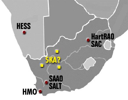
3 SOUTHERN AFRICAN OBSERVATORIES

4 KAROO?
5 WHAT WILL KAT BE? A technology demonstrator Developing technologies expected to be on the critical path of SKA A working science instrument KAT will become part of the SA science infrastructure
6 KAROO ARRAY TELESCOPE 2 antennas (FPA fitted) with directional control (each 15m diameter) in the frequency range of.7ghz to 1.75GHz (extent of the array approx. 2m) 2x RF links (carrier 5GHz, 1 per FPA element) for short haul data transport (2 FPA elements, >1 beams, 25MHz bandwidth, 6 Msps per link, 3.6Gb/second/link) Central digital signal processor (digital receiver, beam former) Radio signals DBBC RFI Karoo, Northern Cape, South Africa HartRAO (26m dish) South Africa HartRAO, Gauteng, User (Scientist) Software for control and monitor VLBI Link (11 Gsps, 16 bits per sample?, 176Gb/s?) High speed computing HartRAO control centre Datacapture Dataprocessing & imaging JIVE
7 KAROO ARRAY TELESCOPE Array of 2 x 15 m reflecting concentrators each fed with a focal plane array (1 x 1 element). Operating frequency range:.7 GHz 1.75 GHz. Dual polarization. Instantaneous bandwidth: 25 MHz each polarization. Antenna array baselines: 2 m 2 m. Array resolution: 142 MHz. >1 independent beams within 1-deg antenna FoV. Tsys < 5 K (<.5 db LNA noise figure). Fully digital with FPGA+HPC back-end. Multiple Correlators (imaging). Located in the Karoo, Northern Cape, South Africa. Four-year development and construction horizon (very tight).
8 KAT SYSTEMS ENGINEERING APPROACH Validation User Requirements definition User spec Verification Operational testing System Design & Modeling System spec System int. & test Subsystem Design & Prototyping Subsystem spec Component spec Verification Verification Manufacture Component int. & test Sub-sys int. & test Verification-driven Bottom-up integration Risk-driven Concurrent design Production Go / no-go
9 KAT ROAD AHEAD Team of professional engineers appointed in key positions to implement subsystems development plans (working with scientist(s)). Systems Engineering approach with tight project management - key milestones and go/no-go decision points. Simulation at all levels of all subsystems. Digital receiver developed for HartRAO 26-m 18cm signal path. Prototype 15-m dish constructed at HartRAO. Evolutionary digital focal plane array developed for HartRAO. Single baseline correlator at HartRAO. Growth of the Research and Technology Collaboration Centre (RTCC). Strong capacity building component to all work. Formalization of industrial and international partnerships. Roll-out of KAT at chosen site.
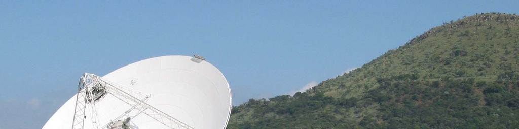
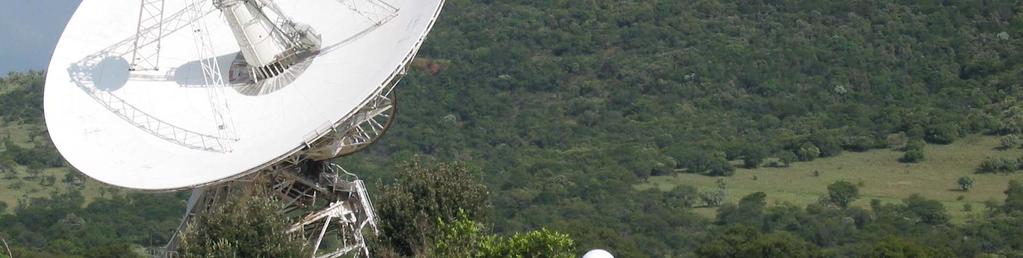
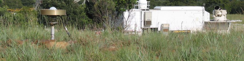
10 HartRAO
11 KAT FPA and DISH
12 ANALYSIS TOOLS AND APPROACH FOCAL FIELDS FEKO (FEldberechnung bei Körpern mit beliebiger Oberfläche) is a 3D full wave simulator, able to analyze small antennas with MoM and larger structures with either PO or UTD. feko@emss.co.za / SolidWorks is a full 3D mechanical design program used extensively in the industry to do mechanical designs in all fields of engineering. FEMAP is a program normally used to analyze mechanical structures. FEKO uses the meshing of FEMAP to input any structure from SolidWorks into the antenna analysis.

13 VIVALDIS IE3D is a full-wave, method-of-moments based electromagnetic simulator solving the current distribution on 3D and multilayer structures of general shape. APPROACH For dish use FEKO/FEMAP/SOLIDWORKS to analyze focal fields. Conjugate matching. In-house software for mutual coupling. Results presented are a summary of a project which has been running for only three months.

14 FEKO BASIC GEOMETRY FOR REFLECTOR, WITH 3D PRESENTATION OF FOCAL REGION FIELD STRENGTH.
15 CONJUGATE FEED MATCHING AND EFFICIENCY Compute focal fields (E, H), hence Poynting vector. Use Robieux s theorem for conjugate match of incident focal fields with the transmit fields of the feed for maximum power transfer. Integrating the focal fields over an ideal feed of radius a gives the power extracted from the focal fields. By dividing by the total power incident on the reflector get the efficiency. By plotting the computed efficiencies with a normalised radius, the efficiencies for all f/d can be displayed on one graph. From this deduce radius of feed for achieving optimum efficiency. There is a minimum radius for various efficiencies in the.4 to.6 f/d range. Since have choice of f/d, examined f/d =.5
16 MAXIMUM EFFICIENCY OF IDEAL CONJUGATE MATCHED FEED
17 EQUAL EFFICIENCY CONTOURS FOR IDEAL FEED RADIUS a/λ VS f/d OR HALF ANGLE
18 GEOMETRY FOR 15 m DIAMETER REFLECTORS
19 SCANNING GEOMETRY FOR REFLECTOR

 AND F/D =.")
20 COMPARISON IN FOCAL POINT NEAR FIELD STRENGTH ON A 15m DISH; F/D =.33 (LEFT) AND F/D =.5 (RIGHT)

 AND F/D =.")
21 COMPARISON IN X-pol FOCAL POINT NEAR FIELD ON A 15m DISH; F/D =.33 (LEFT) AND F/D =.5 (RIGHT)


22 COMPARISON IN FOCAL POINT NEAR FIELD; 4 OFF-AXIS SCANNING ON A 15m DISH; F/D =.33 (LEFT) AND F/D =.5 (RIGHT)


23 COMPARISON IN X-pol FOCAL POINT NEAR FIELD; 4 OFF-AXIS SCANNING ON A 15m DISH; F/D =.33 (LEFT) AND F/D =.5 (RIGHT)

 AND F/D =.")
24 COMPARISON IN FOCAL POINT NEAR FIELD; 3 AT 45 TO PRINCIPAL PLANE ON A 15m DISH; F/D =.33 (LEFT) AND F/D =.5 (RIGHT)

 AND F/D =.")
25 COMPARISON IN X-pol FOCAL POINT NEAR FIELD; 3 OFF-AXIS SCANNING ON A 15m DISH; F/D =.33 (LEFT) AND F/D =.5 (RIGHT)


26 FPA (31,3 ) FPA (37 ) 1 TOTAL E-FIELD STRENGTH AT -3, AND 3 INCOMING WAVE FOR AN OFFSET REFLECTOR WITH FOCAL DISTANCE 7.5m (LEFT) AND 9m (RIGHT).


27 Co-pol E-FIELD STRENGTH AT BORESIGHT INCOMING WAVE FOR AN OFFSET REFLECTOR WITH FOCAL DISTANCE 7.5m (LEFT) AND 9m (RIGHT).


28 X-pol E-FIELD STRENGTH AT BORESIGHT INCOMING WAVE FOR AN OFFSET REFLECTOR WITH FOCAL DISTANCE 7.5m (LEFT) AND 9m (RIGHT).


29 Co-pol E-FIELD STRENGTH AT -3 ON-AXIS INCOMING WAVE FOR AN OFFSET REFLECTOR WITH FOCAL DISTANCE 7.5m (LEFT) AND 9m (RIGHT).


30 Co-pol E-FIELD STRENGTH AT +3 ON-AXIS INCOMING WAVE FOR AN OFFSET REFLECTOR WITH FOCAL DISTANCE 7.5m (LEFT) AND 9m (RIGHT).


31 Co-pol E-FIELD STRENGTH AT +3 OFF-AXIS INCOMING WAVE FOR AN OFFSET REFLECTOR WITH FOCAL DISTANCE 7.5m (LEFT) AND 9m (RIGHT).


32 FIRST ITERATION 4x3 VIVALDI ARRAY INVESTIGATED AT GRINTEK ANTENNAS

33 7MHz RADIATION PATTERN OF VIVALDI ANTENNA IN CENTER OF 4x3 ARRAY ELEMENT 5

34 175MHz RADIATION PATTERN OF VIVALDI ANTENNA IN CENTER OF 4x3 ARRAY ELEMENT 5

35 7MHz RADIATION PATTERN OF VIVALDI ANTENNA ON EDGE OF 4x3 ARRAY ELEMENT 11

36 175MHz RADIATION PATTERN OF VIVALDI ANTENNA ON EDGE OF 4x3 ARRAY ELEMENT 11
37 COUPLING BETWEEN ELEMENTS IN 4 X 3 VIVALDI ARRAY
38 REQUIREMENTS FOR ANTENNA STRUCTURE FOR KAT Operation Gravity [El-range] Temp Rain Ice & Snow Wind incl gusts [ El] [ C] [mm/h] [kg/m²] [km/h] Normal -5 to 9-5 to 4 None None 2 Drive to stow Survival in any position Survival in stow position N/A N/A N/A -2 to N/A -2 to Must be equipped with lightning protection. Surface accuracy: 2 to 3 mm rms (random surface error factor =.979 to.953). Pointing accuracy.1. (set by db variation at 3 db crossover between adjacent beams).
39 Ideal Far-field pattern - 175MHz Relative gain [db] Angle [Degrees] CROSS-OVER REGION BETWEEN TWO ADJACENT MAIN BEAM PATTERNS
40 DRIVE DATA Elevation Azimuth Zenith From true North Range of Motion -5 to Slew speed 2 deg/s 2 deg/s Slew acceleration 2 deg/s² 2 deg/s² Duty cycle (slewing / tracking 2 min
41 HIGH LEVEL FUTURE PLANS FOR KAT R&D, Trade-offs and iterations until end of 26 (technology freeze) Continue investigation of electrical performance of prime focus, offset, folded optics, etc antennas. Investigate alternate elements to Vivaldis for FPAs. Manufacture 1 x 1 x 2 FPA and evaluate (include mutual coupling). Dish mechanical design and investigation of low cost manufacture including pedestal and control. Digital receiver prototype. Digital beamformer prototype. Correlator prototype.
Smart Antennas in Radio Astronomy
 Smart Antennas in Radio Astronomy Wim van Cappellen cappellen@astron.nl Netherlands Institute for Radio Astronomy Our mission is to make radio-astronomical discoveries happen ASTRON is an institute for
Phased Array Feed Design. Stuart Hay 23 October 2009
 Phased Array Feed Design Stuart Hay 23 October 29 Outline Why phased array feeds (PAFs) for radioastronomy? General features and issues of PAF approach Connected-array PAF approach in ASKAP Why PAFs? High
Phased Array Feeds for the SKA. WP2.2.3 PAFSKA Consortium CSIRO ASTRON DRAO NRAO BYU OdP Nancay Cornell U Manchester
 Phased Array Feeds for the SKA WP2.2.3 PAFSKA Consortium CSIRO ASTRON DRAO NRAO BYU OdP Nancay Cornell U Manchester Dish Array Hierarchy Dish Array L5 Elements PAF Dish Single Pixel Feeds L4 Sub systems
L-Band and X-Band Antenna Design and Development for NeXtRAD
 L-Band and X-Band Antenna Design and Development for NeXtRAD S. T. Paine, P. Cheng, D. W. O Hagan, M. R. Inggs, H. D. Griffiths* Department of Electrical Engineering Radar Remote Sensing Group University
November SKA Low Frequency Aperture Array. Andrew Faulkner
 SKA Phase 1 Implementation Southern Africa Australia SKA 1 -mid 250 15m dia. Dishes 0.4-3GHz SKA 1 -low 256,000 antennas Aperture Array Stations 50 350/650MHz SKA 1 -survey 90 15m dia. Dishes 0.7-1.7GHz
A report on KAT7 and MeerKAT status and plans
 A report on KAT7 and MeerKAT status and plans SKA SA, Cape Town Office 3rd Floor, The Park, Park Road, Pinelands, Cape Town, South Africa E mail: tony@hartrao.ac.za This is a short memo on the current
Towards SKA Multi-beam concepts and technology
 Towards SKA Multi-beam concepts and technology SKA meeting Meudon Observatory, 16 June 2009 Philippe Picard Station de Radioastronomie de Nançay philippe.picard@obs-nancay.fr 1 Square Kilometre Array:
March Phased Array Technology. Andrew Faulkner
 Aperture Arrays Michael Kramer Sparse Type of AA selection 1000 Sparse AA-low Sky Brightness Temperature (K) 100 10 T sky A eff Fully sampled AA-mid Becoming sparse Aeff / T sys (m 2 / K) Dense A eff /T
Focal Plane Arrays & SKA
 Focal Plane Arrays & SKA Peter Hall SKA International Project Engineer www.skatelescope.org Dwingeloo, June 20 2005 Outline Today: SKA and antennas Phased arrays and SKA Hybrid SKA possibilities» A hybrid
The Future: Ultra Wide Band Feeds and Focal Plane Arrays
 The Future: Ultra Wide Band Feeds and Focal Plane Arrays Germán Cortés-Medellín NAIC Cornell University 1-1 Overview Chalmers Feed Characterization of Chalmers Feed at Arecibo Focal Plane Arrays for Arecibo
Active Impedance Matched Dual-Polarization Phased Array Feed for the GBT
 Active Impedance Matched Dual-Polarization Phased Array Feed for the GBT Karl F. Warnick, David Carter, Taylor Webb, Brian D. Jeffs Department of Electrical and Computer Engineering Brigham Young University,
Aperture Antennas. Reflectors, horns. High Gain Nearly real input impedance. Huygens Principle
 Antennas 97 Aperture Antennas Reflectors, horns. High Gain Nearly real input impedance Huygens Principle Each point of a wave front is a secondary source of spherical waves. 97 Antennas 98 Equivalence
OPTICS OF SINGLE BEAM, DUAL BEAM & ARRAY RECEIVERS ON LARGE TELESCOPES J A M E S W L A M B, C A L T E C H
 OPTICS OF SINGLE BEAM, DUAL BEAM & ARRAY RECEIVERS ON LARGE TELESCOPES J A M E S W L A M B, C A L T E C H OUTLINE Antenna optics Aberrations Diffraction Single feeds Types of feed Bandwidth Imaging feeds
Instrument Requirements and Options for Meeting the Science Opportunities MHz P. Dewdney A. Gray, B. Veidt
 Instrument Requirements and Options for Meeting the Science Opportunities 300-3000 MHz P. Dewdney A. Gray, B. Veidt Dominion Radio Astrophysical Observatory Herzberg Institute of Astrophysics National
NRC Herzberg Astronomy & Astrophysics
 NRC Herzberg Astronomy & Astrophysics SKA Pre-Construction Update Séverin Gaudet, Canadian Astronomy Data Centre David Loop, Director Astronomy Technology June 2016 update SKA Pre-Construction NRC Involvement
Final Feed Selection Study For the Multi Beam Array System
 National Astronomy and Ionosphere Center Arecibo Observatory Focal Array Memo Series Final Feed Selection Study For the Multi Beam Array System By: Germán Cortés-Medellín CORNELL July/19/2002 U n i v e
SKA station cost comparison
 SKA station cost comparison John D. Bunton, CSIRO Telecommunications and Industrial Physics 4 August 2003 Introduction Current SKA white papers and updates present cost in a variety of ways which makes
May AA Communications. Portugal
 SKA Top-level description A large radio telescope for transformational science Up to 1 million m 2 collecting area Operating from 70 MHz to 10 GHz (4m-3cm) Two or more detector technologies Connected to
Numerical Approach for the Analysis and Optimization of Phased Array Feed Systems
 Numerical Approach for the Analysis and Optimization of Phased Array Feed Systems The Netherlands Institute for Radio Astronomy (ASTRON) Supported by part: - The Netherlands Organization for Scientific
Multi-octave radio frequency systems: Developments of antenna technology in radio astronomy and imaging systems
 Multi-octave radio frequency systems: Developments of antenna technology in radio astronomy and imaging systems Professor Tony Brown School of Electrical and Electronic Engineering University of Manchester
Design, Trade-Off and Advantages of a Reconfigurable Dual Reflector for Ku Band Applications
 Design, Trade-Off and Advantages of a Reconfigurable Dual Reflector for Ku Band Applications Cecilia Cappellin, Knud Pontoppidan TICRA Læderstræde 34 1201 Copenhagen Denmark Email:cc@ticra.com, kp@ticra.com
VLBI2010: In search of Sub-mm Accuracy
 VLBI2010: In search of Sub-mm Accuracy Bill Petrachenko, Nov 6, 2007, University of New Brunswick What is VLBI2010? VLBI2010 is an effort by the International VLBI Service for Geodesy and Astrometry (IVS)
Memo 65 SKA Signal processing costs
 Memo 65 SKA Signal processing costs John Bunton, CSIRO ICT Centre 12/08/05 www.skatelescope.org/pages/page_memos.htm Introduction The delay in the building of the SKA has a significant impact on the signal
EMBRACE DS5 presentation
 EMBRACE presentation Paris 4 th September 2006 ASTRON, The Netherlands Acknowledgement The authors wish to acknowledge the enormous contribution of the whole EMBRACE team presently located at: ASTRON,
EISCAT Scientific Association Technical Specification and Requirements for Antenna Unit V 2.0
 EISCAT Scientific Association Technical Specification and s for Antenna Unit V 2.0 1. Technical Specification for Antenna Unit The EISCAT Scientific Association, also called "EISCAT" throughout this document,
Technology Drivers, SKA Pathfinders P. Dewdney
 Technology Drivers, SKA Pathfinders P. Dewdney Dominion Radio Astrophysical Observatory Herzberg Institute of Astrophysics National Research Council Canada National Research Council Canada Conseil national
CHARECTERIZATION of THE RADIATION PATTERN of a GPS ANTENNA MOUNTED on a SMALL T-TAIL AIRCRAFT in LANDING POSITION
 CHARECTERIZATION of THE RADIATION PATTERN of a GPS ANTENNA MOUNTED on a SMALL T-TAIL AIRCRAFT in LANDING POSITION Abualkair M. Alkhateeb and Daniel N. Aloi Oakland University Electrical and Computer Engineering
ATCA Antenna Beam Patterns and Aperture Illumination
 1 AT 39.3/116 ATCA Antenna Beam Patterns and Aperture Illumination Jared Cole and Ravi Subrahmanyan July 2002 Detailed here is a method and results from measurements of the beam characteristics of the
Traveling Wave Antennas
 Traveling Wave Antennas Antennas with open-ended wires where the current must go to zero (dipoles, monopoles, etc.) can be characterized as standing wave antennas or resonant antennas. The current on these
Array noise temperature measurements at the Parkes PAF Test-bed Facility
 Array noise temperature measurements at the Parkes PAF Test-bed Facility Douglas B. Hayman, Aaron P. Chippendale, Robert D. Shaw and Stuart G. Hay MIDPREP 1 April 2014 COMPUTATIONAL INFORMATICS ASTRONOMY
Phased Array Feeds A new technology for multi-beam radio astronomy
 Phased Array Feeds A new technology for multi-beam radio astronomy Aidan Hotan ASKAP Deputy Project Scientist 2 nd October 2015 CSIRO ASTRONOMY AND SPACE SCIENCE Outline Review of radio astronomy concepts.
A Multi-Fielding SKA Covering the Range 100 MHz 22 GHz. Peter Hall and Aaron Chippendale, CSIRO ATNF 24 November 2003
 A Multi-Fielding SKA Covering the Range 100 MHz 22 GHz Peter Hall and Aaron Chippendale, CSIRO ATNF 24 November 2003 1. Background Various analyses, including the recent IEMT report [1], have noted that
Chalmers Publication Library
 Chalmers Publication Library Analysis of the strut and feed blockage effects in radio telescopes with compact UWB feeds This document has been downloaded from Chalmers Publication Library (CPL). It is
Integrated receivers for mid-band SKA. Suzy Jackson Engineer, Australia Telescope National Facility
 Integrated receivers for mid-band SKA Suzy Jackson Engineer, Australia Telescope National Facility SKADS FP6 Meeting Chateau de Limelette 4-6 November, 2009 Talk overview Mid band SKA receiver challenges
Phased Array Feeds A new technology for wide-field radio astronomy
 Phased Array Feeds A new technology for wide-field radio astronomy Aidan Hotan ASKAP Project Scientist 29 th September 2017 CSIRO ASTRONOMY AND SPACE SCIENCE Outline Review of radio astronomy concepts
Integrated receivers for mid-band SKA. Suzy Jackson Engineer, Australia Telescope National Facility
 Integrated receivers for mid-band SKA Suzy Jackson Engineer, Australia Telescope National Facility ASKAP/SKA Special Technical Brief 23 rd October, 2009 Talk overview Mid band SKA receiver challenges ASKAP
CHAPTER 2 MICROSTRIP REFLECTARRAY ANTENNA AND PERFORMANCE EVALUATION
 43 CHAPTER 2 MICROSTRIP REFLECTARRAY ANTENNA AND PERFORMANCE EVALUATION 2.1 INTRODUCTION This work begins with design of reflectarrays with conventional patches as unit cells for operation at Ku Band in
Phased Array Feeds & Primary Beams
 Phased Array Feeds & Primary Beams Aidan Hotan ASKAP Deputy Project Scientist 3 rd October 2014 CSIRO ASTRONOMY AND SPACE SCIENCE Outline Review of parabolic (dish) antennas. Focal plane response to a
KULLIYYAH OF ENGINEERING
 KULLIYYAH OF ENGINEERING DEPARTMENT OF ELECTRICAL & COMPUTER ENGINEERING ANTENNA AND WAVE PROPAGATION LABORATORY (ECE 4103) EXPERIMENT NO 3 RADIATION PATTERN AND GAIN CHARACTERISTICS OF THE DISH (PARABOLIC)
Introduction to Radar Systems. Radar Antennas. MIT Lincoln Laboratory. Radar Antennas - 1 PRH 6/18/02
 Introduction to Radar Systems Radar Antennas Radar Antennas - 1 Disclaimer of Endorsement and Liability The video courseware and accompanying viewgraphs presented on this server were prepared as an account
Antennas. Greg Taylor. University of New Mexico Spring Astronomy 423 at UNM Radio Astronomy
 Antennas Greg Taylor University of New Mexico Spring 2011 Astronomy 423 at UNM Radio Astronomy Radio Window 2 spans a wide range of λ and ν from λ ~ 0.33 mm to ~ 20 m! (ν = 1300 GHz to 15 MHz ) Outline
Phased Array Feeds for Parkes. Robert Braun Science with 50 Years Young
 Phased Array Feeds for Parkes Robert Braun Science with Parkes @ 50 Years Young Outline PAFs in the SKA context PAFSKA activities Apertif, BYU, NRAO, NAIC, DRAO, ASKAP ASKAP PAF MkI ASKAP PAF MkII Parkes:
Very Long Baseline Interferometry
 Very Long Baseline Interferometry Cormac Reynolds, JIVE European Radio Interferometry School, Bonn 12 Sept. 2007 VLBI Arrays EVN (Europe, China, South Africa, Arecibo) VLBA (USA) EVN + VLBA coordinate
essential requirements is to achieve very high cross-polarization discrimination over a
 INTRODUCTION CHAPTER-1 1.1 BACKGROUND The antennas used for specific applications in satellite communications, remote sensing, radar and radio astronomy have several special requirements. One of the essential
Practical Aspects of Focal Plane Array Testing
 Practical Aspects of Focal Plane Array Testing Lessons from an FPA Test-bed at CSIRO, Marsfield Douglas B. Hayman1-3, Trevor S. Bird2,3, Karu P. Esselle3 and Peter J. Hall4 1 2 3 CSIRO Astronomy and Space
Antenna and Analog Beamformer
 Antenna and Analog Beamformer Requirements The antenna system is responsible for collecting radiation from the sky and presenting a suitably conditioned 80-300 MHz RF signal to the receiver node. Because
Ka by C-COM Satellite Systems Inc.
 Ka-66 The inetvu Ka-66 Drive-Away Antenna is a 66 cm auto-acquire satellite antenna system which can be mounted on the roof of a vehicle for direct broadband access over any configured satellite. The system
HIGH ACCURACY CROSS-POLARIZATION MEASUREMENTS USING A SINGLE REFLECTOR COMPACT RANGE
 HIGH ACCURACY CROSS-POLARIZATION MEASUREMENTS USING A SINGLE REFLECTOR COMPACT RANGE Christopher A. Rose Microwave Instrumentation Technologies 4500 River Green Parkway, Suite 200 Duluth, GA 30096 Abstract
Multi-Mode Antennas for Hemispherical Field-of-View Coverage
 Multi-Mode Antennas for Hemispherical Field-of-View Coverage D.S. Prinsloo P. Meyer R. Maaskant M.V. Ivashina Dept. of Electrical and Electronic Engineering Dept. of Signals and Systems Stellenbosch, South
Focal Plane Array Beamformer for the Expanded GMRT: Initial
 Focal Plane Array Beamformer for the Expanded GMRT: Initial Implementation on ROACH Kaushal D. Buch Digital Backend Group, Giant Metrewave Radio Telescope, NCRA-TIFR, Pune, India kdbuch@gmrt.ncra.tifr.res.in
The System Engineering Mosaic for The African VLBI Network
 The System Engineering Mosaic for The African VLBI Network TL VENKATASUBRAMANI (venkat) Project Manager and Project Engineer 0027 797744725 venkat@ska.ac.za Issue 1 2011/11/16 The 10th International E-VLBI
CHAPTER 5 ANALYSIS OF MICROSTRIP PATCH ANTENNA USING STACKED CONFIGURATION
 1 CHAPTER 5 ANALYSIS OF MICROSTRIP PATCH ANTENNA USING STACKED CONFIGURATION 5.1 INTRODUCTION Rectangular microstrip patch with U shaped slotted patch is stacked, Hexagonal shaped patch with meander patch
Recent Results with the UAV-based Array Verification and Calibration System
 Recent Results with the UAV-based Array Verification and Calibration System Giuseppe Virone POLITECNICO DI TORINO DIATI Framework Research contract between INAF and CNR-IEIIT Title: Power Pattern Measurements
The AAMID consortium: Mid Frequency Aperture Array
 The consortium: Mid Frequency Aperture Array Wim van Cappellen, Consortium Lead Livingstone curves Brought to our attention by Ron Ekers Technological capability leads to discovery in astronomy A single
Performance Analysis of a Patch Antenna Array Feed For A Satellite C-Band Dish Antenna
 Cyber Journals: Multidisciplinary Journals in Science and Technology, Journal of Selected Areas in Telecommunications (JSAT), November Edition, 2011 Performance Analysis of a Patch Antenna Array Feed For
The Australian SKA Pathfinder Project. ASKAP Digital Signal Processing Systems System Description & Overview of Industry Opportunities
 The Australian SKA Pathfinder Project ASKAP Digital Signal Processing Systems System Description & Overview of Industry Opportunities This paper describes the delivery of the digital signal processing
The TWIN-Radiotelescopes Wettzell;
 The TWIN-Radiotelescopes Wettzell Critical Design Points G. Kronschnabl, BKG; Dr. A. Neidhardt, TUM; Dr. K. Pausch, Vertex GmbH; W. Göldi, Mirad; R. Rayet, Callisto; A. Emrich, Omnisys; 1 VLBI 2010 VLBI
Antennas & Receivers in Radio Astronomy
 Antennas & Receivers in Radio Astronomy Mark McKinnon Fifteenth Synthesis Imaging Workshop 1-8 June 2016 Purpose & Outline Purpose: describe how antenna elements can affect the quality of images produced
Notes 21 Introduction to Antennas
 ECE 3317 Applied Electromagnetic Waves Prof. David R. Jackson Fall 018 Notes 1 Introduction to Antennas 1 Introduction to Antennas Antennas An antenna is a device that is used to transmit and/or receive
Dr. John S. Seybold. November 9, IEEE Melbourne COM/SP AP/MTT Chapters
 Antennas Dr. John S. Seybold November 9, 004 IEEE Melbourne COM/SP AP/MTT Chapters Introduction The antenna is the air interface of a communication system An antenna is an electrical conductor or system
Antennas. Greg Taylor. University of New Mexico Spring Astronomy 423 at UNM Radio Astronomy
 Antennas Greg Taylor University of New Mexico Spring 2017 Astronomy 423 at UNM Radio Astronomy Outline 2 Fourier Transforms Interferometer block diagram Antenna fundamentals Types of antennas Antenna performance
Detection of Radio Pulses from Air Showers with LOPES
 Detection of Radio Pulses from Air Showers with LOPES Andreas Horneffer for the LOPES Collaboration Radboud University Nijmegen Radio Emission from Air Showers air showers are known since 1965 to emit
The WVR at Effelsberg. Thomas Krichbaum
 The WVR at Effelsberg Alan Roy Ute Teuber Helge Rottmann Thomas Krichbaum Reinhard Keller Dave Graham Walter Alef The Scanning 18-26 GHz WVR for Effelsberg ν = 18.5 GHz to 26.0 GHz Δν = 900 MHz Channels
EVLA Scientific Commissioning and Antenna Performance Test Check List
 EVLA Scientific Commissioning and Antenna Performance Test Check List C. J. Chandler, C. L. Carilli, R. Perley, October 17, 2005 The following requirements come from Chapter 2 of the EVLA Project Book.
Chapter 5. Array of Star Spirals
 Chapter 5. Array of Star Spirals The star spiral was introduced in the previous chapter and it compared well with the circular Archimedean spiral. This chapter will examine the star spiral in an array
Antenna Fundamentals Basics antenna theory and concepts
 Antenna Fundamentals Basics antenna theory and concepts M. Haridim Brno University of Technology, Brno February 2017 1 Topics What is antenna Antenna types Antenna parameters: radiation pattern, directivity,
IMPROVEMENT OF YAGI UDA ANTENNA RADIATION PATTERN
 International Journal of Mechanical Engineering and Technology (IJMET) Volume 8, Issue 7, July 2017, pp. 636 641, Article ID: IJMET_08_07_071 Available online at http://www.iaeme.com/ijmet/issues.asp?jtype=ijmet&vtype=8&itype=7
Novel Dual-Polarized Spiral Antenna
 Quantum Reversal Inc. White Paper, ALL RIGHTS RESERVED 1 Novel Dual-Polarized Spiral Antenna W. Kunysz, Senior Member Abstract A novel multi-arm (N-arm) spiral antenna that provides flexibe in control
Upgraded Planar Near-Field Test Range For Large Space Flight Reflector Antennas Testing from L to Ku-Band
 Upgraded Planar Near-Field Test Range For Large Space Flight Reflector Antennas Testing from L to Ku-Band Laurent Roux, Frédéric Viguier, Christian Feat ALCATEL SPACE, Space Antenna Products Line 26 avenue
Novel Multi-Beam Radiometers for Accurate Ocean Surveillance
 Novel Multi-Beam Radiometers for Accurate Ocean Surveillance C. Cappellin 1, K. Pontoppidan 1, P.H. Nielsen 1, N. Skou 2, S. S. Søbjærg 2, M. Ivashina 3, O. Iupikov 3, A. Ihle 4, D. Hartmann 4, K. v. t
New Zealand evlbi. Tim Natusch,Sergei Gulyaev, Stuart Weston, Hiroshi Takiguchi
 New Zealand evlbi Tim Natusch,Sergei Gulyaev, Stuart Weston, Hiroshi Takiguchi Institute for Radio Astronomy and Space Research, AUT University Auckland New Zealand November 2011 Johannesburg 1/80 Radio
Monopulse Antenna. Figure 2: sectional picture of an antenna array of a monopulse antenna
 Monopulse Antenna Figure 1: Principle of monopulse antenna Figure 2: sectional picture of an antenna array of a monopulse antenna Under this concept antennae are combined which are built up as an antenna
MELTEK INFOSYSTEMS PVT. LTD. VERTEX MAKE 9MTR ANTENNA I&C FOR DEAL DEHRADUN (BEL PROJECT)
") MELTEK INFOSYSTEMS PVT. LTD. VERTEX MAKE 9MTR ANTENNA I&C FOR DEAL DEHRADUN (BEL PROJECT) Scope of Work 1. Vertex makes 9mtr Antenna Erection, Installation & commissioning and NOCC at DEAL Dehradun. 2.
MELTEK INFOSYSTEMS PVT. LTD. VERTEX MAKE 9MTR ANTENNA I&C FOR DEAL DEHRADUN (BEL PROJECT) Scope of Work 1. Vertex makes 9mtr Antenna Erection, Installation & commissioning and NOCC at DEAL Dehradun. 2.
SKA technology: RF systems & signal processing. Mike Jones University of Oxford
 SKA technology: RF systems & signal processing Mike Jones University of Oxford SKA RF processing Dish receivers Cryogenics RF electronics Fast sampling Antenna processing AA receivers RF gain chain Sampling/antenna
4GHz / 6GHz Radiation Measurement System
 4GHz / 6GHz Radiation Measurement System The MegiQ Radiation Measurement System (RMS) is a compact test system that performs 3-axis radiation pattern measurement in non-anechoic spaces. With a frequency
GBT Spectral Baseline Investigation Rick Fisher, Roger Norrod, Dana Balser (G. Watts, M. Stennes)
") GBT Spectral Baseline Investigation Rick Fisher, Roger Norrod, Dana Balser (G. Watts, M. Stennes) Points to Note: Wider bandwidths than were used on 140 Foot Cleaner antenna so other effects show up Larger
GBT Spectral Baseline Investigation Rick Fisher, Roger Norrod, Dana Balser (G. Watts, M. Stennes) Points to Note: Wider bandwidths than were used on 140 Foot Cleaner antenna so other effects show up Larger
Specifications Sheet: PRIME FOCUS MESH DISH KIT 1.2 Meter DISH
 Specifications Sheet: PRIME FOCUS MESH DISH KIT 1.2 Meter DISH Available F/D: 0.35 / 0.4 / 0.45 / 0.5 (Example Picture: 1.2 Meter dish (6mm mesh) 1M2_KIT_SPEC RF HAMDESIGN www.rfhamdesign.com This 8-Rib
Miniature Deployable High Gain Antenna for CubeSats
 Phantom Works Miniature Deployable High Gain Antenna for CubeSats Charles S. Scott MacGillivray Office: (714) 372-1617 e-mail: charles.s.macgillivray@boeing.com Mobile: (714) 392-9095 e-mail: zserfv23@gmail.com
ADVANCED 14/12 AND 30/20 GHz MULTIPLE BEAM ANTENNA TECHNOLOGY FOR COMMUNICATIONS SATELLITES
 ADVANCED 14/12 AND 30/20 GHz MULTIPLE BEAM ANTENNA TECHNOLOGY FOR COMMUNICATIONS SATELLITES C.C. Chen TRW Defense and Space Systems Group Redondo Beach, CA 90278 ABSTRACT This paper discusses recent TRW
CHAPTER 3 SIDELOBE PERFORMANCE OF REFLECTOR / ANTENNAS
 16 CHAPTER 3 SIDELOBE PERFORMANCE OF REFLECTOR / ANTENNAS 3.1 INTRODUCTION In the past many authors have investigated the effects of amplitude and phase distributions over the apertures of both array antennas
Evolution of the Capabilities of the ALMA Array
 Evolution of the Capabilities of the ALMA Array This note provides an outline of how we plan to build up the scientific capabilities of the array from the start of Early Science through to Full Operations.
Photonic Integrated Beamformer for Broadband Radio Astronomy
 M. Burla, D. A. I. Marpaung, M. R. H. Khan, C. G. H. Roeloffzen Telecommunication Engineering group University of Twente, Enschede, The Netherlands P. Maat, K. Dijkstra ASTRON, Dwingeloo, The Netherlands
DANIEL JACOBUS LUDICK
 Curriculum Vitae DANIEL JACOBUS LUDICK Electrical & Electronic Engineer (PhD) Email: danie.ludick@gmail.com Overview Danie matriculated in 2003 from Jan van Riebeeck High school in Cape Town. He received
Design of a Novel Compact Cup Feed for Parabolic Reflector Antennas
 Progress In Electromagnetics Research Letters, Vol. 64, 81 86, 2016 Design of a Novel Compact Cup Feed for Parabolic Reflector Antennas Amir Moallemizadeh 1,R.Saraf-Shirazi 2, and Mohammad Bod 2, * Abstract
ANTENNA INTRODUCTION / BASICS
 ANTENNA INTRODUCTION / BASICS RULES OF THUMB: 1. The Gain of an antenna with losses is given by: 2. Gain of rectangular X-Band Aperture G = 1.4 LW L = length of aperture in cm Where: W = width of aperture
Reflector antennas and their feeds
 Reflector antennas and their feeds P. Hazdra, M. Mazanek,. hazdrap@fel.cvut.cz Department of Electromagnetic Field Czech Technical University in Prague, FEE www.elmag.org v. 23.4.2015 Outline Simple reflector
ALMA Band 9 technology for CCAT. Andrey Baryshev
 ALMA Band 9 technology for CCAT Andrey Baryshev ALMA band 9 group SRON A. Baryshev B. Jackson R. Hesper J. Adema F.P. Mena J. Barkhoff M. Bekema K. Keizer G. Gerlofsma A. Koops J. Panman W. Wild TUDelft
ngvla The Next Generation Very Large Array
 Perspective from the Technical Advisory Council Melissa Soriano, Jet Propulsion Laboratory, California Institute of Technology James Lamb, California Institute of Technology ngvla 2017 California Institute
Observing Modes and Real Time Processing
 2010-11-30 Observing with ALMA 1, Observing Modes and Real Time Processing R. Lucas November 30, 2010 Outline 2010-11-30 Observing with ALMA 2, Observing Modes Interferometry Modes Interferometry Calibrations
An Array Feed Radial Basis Function Tracking System for NASA s Deep Space Network Antennas
 An Array Feed Radial Basis Function Tracking System for NASA s Deep Space Network Antennas Ryan Mukai Payman Arabshahi Victor A. Vilnrotter California Institute of Technology Jet Propulsion Laboratory
Antennas and Receivers in Radio Astronomy
 Antennas and Receivers in Radio Astronomy Mark McKinnon Eleventh Synthesis Imaging Workshop Socorro, June 10-17, 2008 Outline 2 Context Types of antennas Antenna fundamentals Reflector antennas Mounts
The Shaped Coverage Area Antenna for Indoor WLAN Access Points
 The Shaped Coverage Area Antenna for Indoor WLAN Access Points A.BUMRUNGSUK and P. KRACHODNOK School of Telecommunication Engineering, Institute of Engineering Suranaree University of Technology 111 University
Overview of the SKA. P. Dewdney International SKA Project Engineer Nov 9, 2009
 Overview of the SKA P. Dewdney International SKA Project Engineer Nov 9, 2009 Outline* 1. SKA Science Drivers. 2. The SKA System. 3. SKA technologies. 4. Trade-off space. 5. Scaling. 6. Data Rates & Data
Space Frequency Coordination Group
 Space Frequency Coordination Group Report SFCG 38-1 POTENTIAL RFI TO EESS (ACTIVE) CLOUD PROFILE RADARS IN 94.0-94.1 GHZ FREQUENCY BAND FROM OTHER SERVICES Abstract This new SFCG report analyzes potential
Giant Metrewave Radio Telescope (GMRT) - Introduction, Current System & ugmrt
 - Introduction, Current System & ugmrt") Giant Metrewave Radio Telescope (GMRT) - Introduction, Current System & ugmrt Kaushal D. Buch Digital Backend Group, Giant Metrewave Radio Telescope kdbuch@gmrt.ncra.tifr.res.in Low frequency dipole array
Giant Metrewave Radio Telescope (GMRT) - Introduction, Current System & ugmrt Kaushal D. Buch Digital Backend Group, Giant Metrewave Radio Telescope kdbuch@gmrt.ncra.tifr.res.in Low frequency dipole array
SKA Correlator Input Data Rate
 SKA Correlator Input Data Rate John D. Bunton, CSIRO ICT Centre 14 November 003 Introduction One of the major costs in the SKA is data transport from the antenna to the central beamformer or correlator.
Circular Focal Plane Array for Astronomic Applications
 International Workshop on Phased Array Antenna Systems for Radio Astronomy Circular Focal Plane Array for Astronomic Applications Rémi Sarkis, Christophe Craeye May 3-5, 21 Provo, Utah, USA 1 Introduction
The magnetic surface current density is defined in terms of the electric field at an aperture as follows: 2E n (6.1)
") Chapter 6. Aperture antennas Antennas where radiation occurs from an open aperture are called aperture antennas. xamples include slot antennas, open-ended waveguides, rectangular and circular horn antennas,
Chapter 6. Aperture antennas Antennas where radiation occurs from an open aperture are called aperture antennas. xamples include slot antennas, open-ended waveguides, rectangular and circular horn antennas,
Correlator Development at Haystack. Roger Cappallo Haystack-NRAO Technical Mtg
 Correlator Development at Haystack Roger Cappallo Haystack-NRAO Technical Mtg. 2006.10.26 History of Correlator Development at Haystack ~1973 Mk I 360 Kb/s x 2 stns. 1981 Mk III 112 Mb/s x 4 stns. 1986
SKA DISH ELEMENT TECHNICAL SOLUTION
 SKA DISH ELEMENT TECHNICAL SOLUTION Document number... SKA TEL.DSH.MGT CSIRO TS 004 Revision... 1 Author....SKADC Consortium Date... 06 June 2013 Status... Released Name Designation Affiliation Date Signature