Overview of the SKA. P. Dewdney International SKA Project Engineer Nov 9, 2009
|
|
|
- Eugenia Rogers
- 5 years ago
- Views:
Transcription

1 Overview of the SKA P. Dewdney International SKA Project Engineer Nov 9, 2009
2 Outline* 1. SKA Science Drivers. 2. The SKA System. 3. SKA technologies. 4. Trade-off space. 5. Scaling. 6. Data Rates & Data Processing 7. Dynamic range & Calibration. 8. Computing and Software Development. * See also The Square Kilometre Array, Proceedings IEEE, Vol 97, No 8, Aug
3 What is the SKA? A large radio telescope with 5 key science drivers & a very wide range of science impact. It comprises a number of sensor types spread over 1000s of km, connected to a signal processor and HPC system via optical fibre network SKA-low : MHz SKA-mid: 300 MHz-10 GHz SKA-high: GHz Being planned for completion Planned for completion later. It is a global program involving more than 50 institutes in 19 countries. 3


4 SKA Key Science Drivers ORIGINS Probing the Dark Ages When & how were the first stars formed? Cosmology and Galaxy Evolution Galaxies, Dark Energy and Dark Matter Astrobiology What are the conditions for life and where can it be found? FUNDAMENTAL FORCES Strong-field tests of General Relativity Was Einstein correct? Origin & Evolution of Cosmic Magnetism Where does magnetism come from? plus The Exploration of the Unknown Science with the Square Kilometre Array (2004, eds. C. Carilli & S. Rawlings, New Astron. Rev., 48)

5 Concise Picture of Technology Options Numbers of dishes ( ) depends on whether Phased Array Feeds and/or Aperture Arrays are used in the SKA. Each technology is characterized by a frequency range and field of view. 5
6


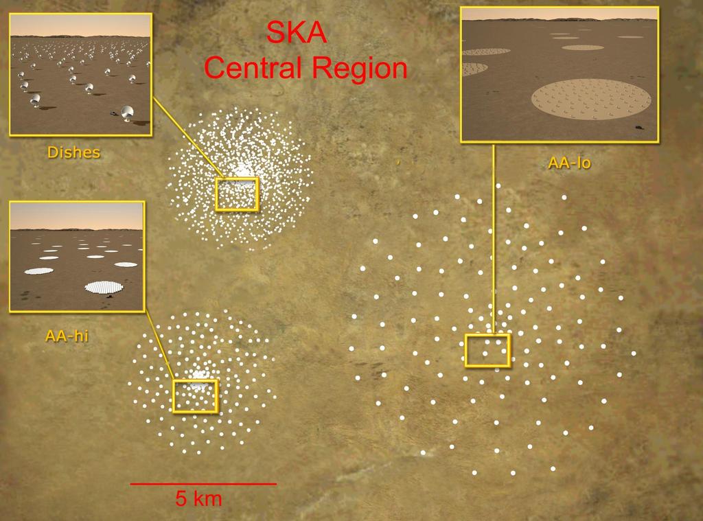
7 Site Configuration Schematic Comms links Dense aperture arrays Signal Processing Facility 1500 dishes (15m diameter) in central ~5 km Central Region ~20 km from 5 km to km Sparse aperture Station arrays Dishes spread along spirals 40 remote stations 200 to >3000 km Dishes Dense AA Sparse AA ~200 km Not to Scale 7
 15m Dishes with Phased Array Feeds 2000 8")
8 Potential Maximum System Size (i.e. if we do everything) 15m Dishes with Single Pixel Feeds 3000 Sparse AAs ~10 6 m 2 Dense AAs 700,000 m 2 (250 x 60m dia. stations) 15m Dishes with Phased Array Feeds

 Need 250 stations for 10,000 m 2 K -1 sensitivity (for")
9 Dense Aperture Array Station ~256 tiles x 256 elements per tile 2 polarisations per element Sample rate ~ 2.5 Gsamp/s 4 bits/ sample 56 m diameter 250 stations Tsys Target 35K 56m diameter array => 2463 m x 2-pol elements m -2 (30cm) Need 250 stations for 10,000 m 2 K -1 sensitivity (for antenna efficiency 75%, Tsys = 35K) 300MHz to 1GHz (700MHz bandwidth) Processing Bunker 9 of 35


10 Dishes ATA 42x6m hydroformed dishes South MeerKAT Africa ASKAP 36x12m panel dishes Prototype 80x12m 15 m composite composite dish dishes CART 10 m composite prototype
11 Offset design


12 Multi-pixels at mid frequencies with dishes + phased-array-feeds ASKAP Chequer-board phased array (ASKAP, Australia) Chequer-board phased array (ASKAP, Australia) chequer board array ASKAP, Australia APERTIF (Astron, NL) DRAO Canada Vivaldi arrays
13 Cost and Feasibility Feedback Science Case Science Requirements (Design Reference Mission) Case Studies Technical R&D Eng. Simulations Prototypes Pathfinders Configurations Costing Readiness Design Cycle Design Reference Mission Assembly of science case studies that can be used to define the upper envelope of technical requirements of the telescope. Not another science case. Does not include all science. Includes all key science as a minimum. Engineering Design & Cost Implementation of this flow requires a series of analyses, measurements and tests, and a means of making science choices, trades and technical decisions. *Design Reference Mission 13
14 Scaling & Cost SKA scale is much larger than current radio telescopes. Many of the techniques used in current radio telescopes do not scale efficiently. Need highly integrated sub-systems, power efficient. Production engineering (DFM) very important. Countries with low-cost production may be needed for some aspects. Industrial involvement SKA is large enough to attract industry involvement. 14
15 Generalized Synthesis Radio Telescope Model Field-of-View Ω Ω synth Antenna Digital Thing Printer Radio Waves Data Flow Data Flow Data Flow Collector A tot N ap B or Correlation Processor Work Ω p Imaging Processor Work 2 R ap BA tot / 2 WC Nap( Atot / ) B R W tot C 2 WI R c B nchannelements B A p synth N ap Images and Spectra 15
16 R BA / 2 ap tot W C N 2 ap B 2 WC Nap( Atot / ) B R C B A tot 2 N ap = number of beamforming apertures = wavelength = center frequency B = total bandwidth Technology-Independent Proportionalities* p synth N ap Total Data Rate to Central Processor Correlator Size for SPFs Correlator Size for PAFs or AAs. Output Data Rate from Central Processor A tot = total collecting area = Total FoV p = processed FoV Synth = synthesized beamwidth *Approximate relations. 16
17 Single Beam with Fringe Pattern 2 / day Fringes / D max Ω p d PFoV 17
18 Data Rate from Antennas R BN ap ap N beam From this equation, substituting the following: A N beam tot Nap beam Aap Yields: R BA / 2 ap tot beam Nbeam A 2 ap 2 A ap Note: For the single-pixel feed case, N beam = 1 and Ω beam = Ω. 18
19 Correlation Work W C 2 N N nchan ap beam From this equation, substituting the following: N ap A A tot ap Nbeam A 2 ap B n chan Yields: 2 WC Nap( Atot / ) B Note: For the single-pixel feed case, N beam = 1, and W C N ap B. 19
20 C n chan baselines B / 1 D c Correlator Output Data Rate R N n ( 1/ t) N chan Yields: R C beam From this equation, substituting the following: 2 Nbaselines N ap / / max p 1/ 2 p p t D max 1 p n chan B B Dmax Nbeam 2 A tot 2 D A N tot ap p max 1/ 2 1/ t p synth 1/ 2 p N ap 20
21 Imaging Dynamic Range Imaging Dynamic Range Ratio of brightest object in image field to weakest detectable object. Ideally limited by natural noise, not systematics. Don t want to build a supersensitive (high A/T sys ) telescope: then find that it hits a limit after 50-hrs integration, which is then irreducible because of systematic errors. i.e. Systematics not fully understood, or rapidly time variable. High DR is a system issue. need to consider the whole signal chain, signal processing and imaging as a system. 21
22 e.g. Reflector Pointing High DR imaging will require very accurate antenna pointing Strong sources near ½ power point very sensitive to pointing (P 0.72 [/FWHM] for Gaussian). For P < 10-6, 1.4 X 10⁻⁶ FWHM. Clearly this antenna spec cannot be met by mechanical means alone. Self-calibration, mosaicing and other solving techniques will be necessary to effectively recover pointing errors. Simulations and testing with existing telescopes will be needed to verify and delineate limitations. Recovered pointing could meet the original spec.
23 Modelling/Calibration 1. Cannot model and calibrate systematic effects (errors) that are not fully understood. Sounds obvious but years of work on specific telescopes have typically been required to understand the subtle systematic effects needed to achieve high DR imaging. The lessons learned from this work must be applied to the SKA from the beginning. Unprecedented level of collaboration needed for the SKA between design engineers and astronomers (also crosstraining).
24 Modelling/Calibration (cont d) 2. Degrees of Freedom Cannot solve for more parameters than there is information to support. Information theory provides a fundamental basis for evaluating combinations of measurements, assumptions, and a-priori information. Theory originally arose from studies of the amount of information that can be transmitted over a noisy channel. Recent work on LOFAR by van der Tol, Jeffs, and van der Veen is an example of a formal information theory approach to this problem. Information theory provides guidance on optimum use of information, but does not provide guidance on actually understanding sources of errors. Errors with direction-dependency, frequency-dependency or time-dependency add greatly to the number of parameters to be solved for. e.g. beam-errors, ionospheric propagation effects, etc.
25 3. Time Variability Modelling/Calibration (cont d) Strictly speaking time-variability is a subset of previous slide. All analog systems drift. e.g. Gains of amplifiers are functions of temperature. e.g. Switching levels and sample intervals in A/D converters vary in complex, non-random ways. Characteristic drift times cannot be too short. signal-to-noise will limit the frequency of calibrations, especially those based on celestial sources. e.g. bandpass cals require high signal-to-noise. Digital systems do not drift. Much better than analog systems. Cost of digital systems is high compared with analog, especially including power. Subject to bit errors at a low level.
26 Key Instrumental Issues Stability Linearity Calibratibility System Temperature Cost Capital Operations All Contribute to Dynamic Range 26
27 Software Development Hardware production and scaling relationships do not seem to apply to software. Survey speed, time-variable astronomy implies very high data flows and possibly number crunching. Scale of SKA implies the use of supercomputer architectures (1000 s of cores) for which there is no current body of code. 27
28 Development Stage Simulation Some aspects of design. Needed to plan surveys and other Engineering Design S/W Available for $/ : very expensive. S/W Development Tools Types of SKA S/W Operations Stage Observation preparation. Telescope operations Monitor & Control Visualization & Display Calibration & Imaging Special Data Processing (e.g. Pulsars) Data management and distribution Middleware Data bases Storage management: speed of access. Data paths to outside world. Science data processing.
29 Compute Requirements for Dish-based Version of SKA Central Computing Based on Facility (Example) Input data rate* 44 x Byte s -1 av ge from correlator (4-Byte real s) Imaging Processor flops / input number (EVLA Memo 24) Archive 0.1 to 1 ExaByte * From correlator with 10 5 chans out, ~14000 input data streams, dumped every 200 ms.
30 A Potential Code-development Operational Model PI Support Survey Teams Code Flow Science Data Products Code Integration and test at CPC. SKA Central Compute Facility Globe Regional Science Centres 30
31 End 31
Smart Antennas in Radio Astronomy
 Smart Antennas in Radio Astronomy Wim van Cappellen cappellen@astron.nl Netherlands Institute for Radio Astronomy Our mission is to make radio-astronomical discoveries happen ASTRON is an institute for
Phased Array Feeds for the SKA. WP2.2.3 PAFSKA Consortium CSIRO ASTRON DRAO NRAO BYU OdP Nancay Cornell U Manchester
 Phased Array Feeds for the SKA WP2.2.3 PAFSKA Consortium CSIRO ASTRON DRAO NRAO BYU OdP Nancay Cornell U Manchester Dish Array Hierarchy Dish Array L5 Elements PAF Dish Single Pixel Feeds L4 Sub systems
Towards SKA Multi-beam concepts and technology
 Towards SKA Multi-beam concepts and technology SKA meeting Meudon Observatory, 16 June 2009 Philippe Picard Station de Radioastronomie de Nançay philippe.picard@obs-nancay.fr 1 Square Kilometre Array:
March Phased Array Technology. Andrew Faulkner
 Aperture Arrays Michael Kramer Sparse Type of AA selection 1000 Sparse AA-low Sky Brightness Temperature (K) 100 10 T sky A eff Fully sampled AA-mid Becoming sparse Aeff / T sys (m 2 / K) Dense A eff /T
May AA Communications. Portugal
 SKA Top-level description A large radio telescope for transformational science Up to 1 million m 2 collecting area Operating from 70 MHz to 10 GHz (4m-3cm) Two or more detector technologies Connected to
Technology Drivers, SKA Pathfinders P. Dewdney
 Technology Drivers, SKA Pathfinders P. Dewdney Dominion Radio Astrophysical Observatory Herzberg Institute of Astrophysics National Research Council Canada National Research Council Canada Conseil national
November SKA Low Frequency Aperture Array. Andrew Faulkner
 SKA Phase 1 Implementation Southern Africa Australia SKA 1 -mid 250 15m dia. Dishes 0.4-3GHz SKA 1 -low 256,000 antennas Aperture Array Stations 50 350/650MHz SKA 1 -survey 90 15m dia. Dishes 0.7-1.7GHz
Roshene McCool Domain Specialist in Signal Transport and Networks SKA Program Development Office
 Roshene McCool Domain Specialist in Signal Transport and Networks SKA Program Development Office mccool@skatelescope.org SKA A description Outline Specifications Long Baselines in the SKA Science drivers
SKA1 low Baseline Design: Lowest Frequency Aspects & EoR Science
 SKA1 low Baseline Design: Lowest Frequency Aspects & EoR Science 1 st science Assessment WS, Jodrell Bank P. Dewdney Mar 27, 2013 Intent of the Baseline Design Basic architecture: 3-telescope, 2-system
Dense Aperture Array for SKA
 Dense Aperture Array for SKA Steve Torchinsky EMBRACE Why a Square Kilometre? Detection of HI in emission at cosmological distances R. Ekers, SKA Memo #4, 2001 P. Wilkinson, 1991 J. Heidmann, 1966! SKA
Multi-octave radio frequency systems: Developments of antenna technology in radio astronomy and imaging systems
 Multi-octave radio frequency systems: Developments of antenna technology in radio astronomy and imaging systems Professor Tony Brown School of Electrical and Electronic Engineering University of Manchester
Instrument Requirements and Options for Meeting the Science Opportunities MHz P. Dewdney A. Gray, B. Veidt
 Instrument Requirements and Options for Meeting the Science Opportunities 300-3000 MHz P. Dewdney A. Gray, B. Veidt Dominion Radio Astrophysical Observatory Herzberg Institute of Astrophysics National
A Multi-Fielding SKA Covering the Range 100 MHz 22 GHz. Peter Hall and Aaron Chippendale, CSIRO ATNF 24 November 2003
 A Multi-Fielding SKA Covering the Range 100 MHz 22 GHz Peter Hall and Aaron Chippendale, CSIRO ATNF 24 November 2003 1. Background Various analyses, including the recent IEMT report [1], have noted that
Radio Interferometers Around the World. Amy J. Mioduszewski (NRAO)
") Radio Interferometers Around the World Amy J. Mioduszewski (NRAO) A somewhat biased view of current interferometers Limited to telescopes that exist or are in the process of being built (i.e., I am not
Radio Interferometers Around the World Amy J. Mioduszewski (NRAO) A somewhat biased view of current interferometers Limited to telescopes that exist or are in the process of being built (i.e., I am not
SKA Phase 1: Costs of Computation. Duncan Hall CALIM 2010
 SKA Phase 1: Costs of Computation Duncan Hall CALIM 2010 2010 August 24, 27 Outline Motivation Phase 1 in a nutshell Benchmark from 2001 [EVLA Memo 24] Some questions Amdahl s law overrides Moore s law!
Phased Array Feed Design. Stuart Hay 23 October 2009
 Phased Array Feed Design Stuart Hay 23 October 29 Outline Why phased array feeds (PAFs) for radioastronomy? General features and issues of PAF approach Connected-array PAF approach in ASKAP Why PAFs? High
Focal Plane Arrays & SKA
 Focal Plane Arrays & SKA Peter Hall SKA International Project Engineer www.skatelescope.org Dwingeloo, June 20 2005 Outline Today: SKA and antennas Phased arrays and SKA Hybrid SKA possibilities» A hybrid
The SKA New Instrumentation: Aperture Arrays
 The SKA New Instrumentation: Aperture Arrays A. van Ardenne, A.J. Faulkner, and J.G. bij de Vaate Abstract The radio frequency window of the Square Kilometre Array is planned to cover the wavelength regime
LOFAR: Special Issues
 Netherlands Institute for Radio Astronomy LOFAR: Special Issues John McKean (ASTRON) ASTRON is part of the Netherlands Organisation for Scientific Research (NWO) 1 Preamble http://www.astron.nl/~mckean/eris-2011-2.pdf
NRC Herzberg Astronomy & Astrophysics
 NRC Herzberg Astronomy & Astrophysics SKA Pre-Construction Update Séverin Gaudet, Canadian Astronomy Data Centre David Loop, Director Astronomy Technology June 2016 update SKA Pre-Construction NRC Involvement
Phased Array Feeds A new technology for multi-beam radio astronomy
 Phased Array Feeds A new technology for multi-beam radio astronomy Aidan Hotan ASKAP Deputy Project Scientist 2 nd October 2015 CSIRO ASTRONOMY AND SPACE SCIENCE Outline Review of radio astronomy concepts.
Phased Array Feeds & Primary Beams
 Phased Array Feeds & Primary Beams Aidan Hotan ASKAP Deputy Project Scientist 3 rd October 2014 CSIRO ASTRONOMY AND SPACE SCIENCE Outline Review of parabolic (dish) antennas. Focal plane response to a
All-Digital Wideband Space-Frequency Beamforming for the SKA Aperture Array
 All-Digital Wideband Space-Frequency Beamforming for the SKA Aperture Array Vasily A. Khlebnikov, 44-0865-273302, w.khlebnikov@ieee.org, Kristian Zarb-Adami, 44-0865-273302, kza@astro.ox.ac.uk, Richard
ASKAP Industry technical briefing. Tim Cornwell, ASKAP Computing Project Lead Australian Square Kilometre Array Pathfinder
 ! ASKAP Industry technical briefing Tim Cornwell, ASKAP Computing Project Lead Australian Square Kilometre Array Pathfinder The Square Kilometre Array 2020 era radio telescope Very large collecting area
Memo 111. SKADS Benchmark Scenario Design and Costing 2 (The SKA Phase 2 AA Scenario)
") Memo 111 SKADS Benchmark Scenario Design and Costing 2 (The SKA Phase 2 AA Scenario) R. Bolton G. Harris A. Faulkner T. Ikin P. Alexander M. Jones S. Torchinsky D. Kant A. van Ardenne D. Kettle P. Wilkinson
Memo 111 SKADS Benchmark Scenario Design and Costing 2 (The SKA Phase 2 AA Scenario) R. Bolton G. Harris A. Faulkner T. Ikin P. Alexander M. Jones S. Torchinsky D. Kant A. van Ardenne D. Kettle P. Wilkinson
The Australian SKA Pathfinder Project. ASKAP Digital Signal Processing Systems System Description & Overview of Industry Opportunities
 The Australian SKA Pathfinder Project ASKAP Digital Signal Processing Systems System Description & Overview of Industry Opportunities This paper describes the delivery of the digital signal processing
Array noise temperature measurements at the Parkes PAF Test-bed Facility
 Array noise temperature measurements at the Parkes PAF Test-bed Facility Douglas B. Hayman, Aaron P. Chippendale, Robert D. Shaw and Stuart G. Hay MIDPREP 1 April 2014 COMPUTATIONAL INFORMATICS ASTRONOMY
Phased Array Feeds for Parkes. Robert Braun Science with 50 Years Young
 Phased Array Feeds for Parkes Robert Braun Science with Parkes @ 50 Years Young Outline PAFs in the SKA context PAFSKA activities Apertif, BYU, NRAO, NAIC, DRAO, ASKAP ASKAP PAF MkI ASKAP PAF MkII Parkes:
Integrated receivers for mid-band SKA. Suzy Jackson Engineer, Australia Telescope National Facility
 Integrated receivers for mid-band SKA Suzy Jackson Engineer, Australia Telescope National Facility ASKAP/SKA Special Technical Brief 23 rd October, 2009 Talk overview Mid band SKA receiver challenges ASKAP
Recent Developments in Measuring Signal and Noise in Phased Array Feeds at CSIRO
 Recent Developments in Measuring Signal and Noise in Phased Array Feeds at CSIRO A. P. Chippendale, D. McConnell, K. Bannister, N. Nikolic, A. W. Hotan, K. W. Smart, R. D. Shaw, D. B. Hayman, S. G. Hay
The AAMID consortium: Mid Frequency Aperture Array
 The consortium: Mid Frequency Aperture Array Wim van Cappellen, Consortium Lead Livingstone curves Brought to our attention by Ron Ekers Technological capability leads to discovery in astronomy A single
ARRAY DESIGN AND SIMULATIONS
 ARRAY DESIGN AND SIMULATIONS Craig Walker NRAO Based in part on 2008 lecture by Aaron Cohen TALK OUTLINE STEPS TO DESIGN AN ARRAY Clarify the science case Determine the technical requirements for the key
The Future: Ultra Wide Band Feeds and Focal Plane Arrays
 The Future: Ultra Wide Band Feeds and Focal Plane Arrays Germán Cortés-Medellín NAIC Cornell University 1-1 Overview Chalmers Feed Characterization of Chalmers Feed at Arecibo Focal Plane Arrays for Arecibo
Memo 130. SKA Phase 1: Preliminary System Description
 Memo 130 SKA Phase 1: Preliminary System Description P. Dewdney (SPDO) J-G bij de Vaate (ASTRON) K. Cloete (SPDO) A. Gunst (ASTRON) D. Hall (SPDO) R. McCool (SPDO) N. Roddis (SPDO) W. Turner (SPDO) November
SKA technology: RF systems & signal processing. Mike Jones University of Oxford
 SKA technology: RF systems & signal processing Mike Jones University of Oxford SKA RF processing Dish receivers Cryogenics RF electronics Fast sampling Antenna processing AA receivers RF gain chain Sampling/antenna
Practical Aspects of Focal Plane Array Testing
 Practical Aspects of Focal Plane Array Testing Lessons from an FPA Test-bed at CSIRO, Marsfield Douglas B. Hayman1-3, Trevor S. Bird2,3, Karu P. Esselle3 and Peter J. Hall4 1 2 3 CSIRO Astronomy and Space
Memo 65 SKA Signal processing costs
 Memo 65 SKA Signal processing costs John Bunton, CSIRO ICT Centre 12/08/05 www.skatelescope.org/pages/page_memos.htm Introduction The delay in the building of the SKA has a significant impact on the signal
Phased Array Feeds A new technology for wide-field radio astronomy
 Phased Array Feeds A new technology for wide-field radio astronomy Aidan Hotan ASKAP Project Scientist 29 th September 2017 CSIRO ASTRONOMY AND SPACE SCIENCE Outline Review of radio astronomy concepts
More Radio Astronomy
 More Radio Astronomy Radio Telescopes - Basic Design A radio telescope is composed of: - a radio reflector (the dish) - an antenna referred to as the feed on to which the radiation is focused - a radio
TheSquareKilometreArray
 INVITED PAPER TheSquareKilometreArray This telescope, to be the largest in the world, will probe the evolution of black holes as well as the basic properties, birth and death of the Universe. By Peter
Memo 8. US SKA Technology Development Project Memo Series. TDP Antenna Specification: Structural Mechanical Portion. Matt Fleming.
 Memo 8 US SKA Technology Development Project Memo Series TDP Antenna Specification: Structural Mechanical Portion Matt Fleming Rev B, April 2009 US SKA TDP TDP Antenna Specification Structural Mechanical
Aperture Arrays for the SKA: the SKADS White Paper
 Design Study 8 Task 1 Deliverable 0.5 : DS White Paper Authors The SKADS Teams System Group: Andrew Faulkner (Chair) Steve Torchinsky Paul Alexander Steve Rawlings Dion Kant Stelio Montebugnoli Philippe
SKA-low and the Aperture Array Verification System
 SKA-low and the Aperture Array Verification System Randall Wayth AADCC Project Scientist On behalf of the Aperture Array Design & Construction Consortium (AADCC) AADCC partners ASTRON (Netherlands) ICRAR/Curtin
ngvla Technical Overview
 ngvla Technical Overview Mark McKinnon, Socorro, NM Outline ngvla Nominal Technical Parameters Technical Issues to Consider in Science Use Cases Programmatics Additional Information Pointed or Survey Telescope?
Numerical Approach for the Analysis and Optimization of Phased Array Feed Systems
 Numerical Approach for the Analysis and Optimization of Phased Array Feed Systems The Netherlands Institute for Radio Astronomy (ASTRON) Supported by part: - The Netherlands Organization for Scientific
EVLA Memo 105. Phase coherence of the EVLA radio telescope
 EVLA Memo 105 Phase coherence of the EVLA radio telescope Steven Durand, James Jackson, and Keith Morris National Radio Astronomy Observatory, 1003 Lopezville Road, Socorro, NM, USA 87801 ABSTRACT The
MWA Antenna Description as Supplied by Reeve
 MWA Antenna Description as Supplied by Reeve Basic characteristics: Antennas are shipped broken down and require a few minutes to assemble in the field Each antenna is a dual assembly shaped like a bat
Chalmers Publication Library
 Chalmers Publication Library Analysis of the strut and feed blockage effects in radio telescopes with compact UWB feeds This document has been downloaded from Chalmers Publication Library (CPL). It is
THE KAROO ARRAY TELESCOPE (KAT) & FPA EFFORT IN SOUTH AFRICA
 & FPA EFFORT IN SOUTH AFRICA") THE KAROO ARRAY TELESCOPE (KAT) & FPA EFFORT IN SOUTH AFRICA Dr. Dirk Baker (KAT FPA Sub-system Manager) Prof. Justin Jonas (SKA SA Project Scientist) Ms. Anita Loots (KAT Project Manager) Mr. David de
THE KAROO ARRAY TELESCOPE (KAT) & FPA EFFORT IN SOUTH AFRICA Dr. Dirk Baker (KAT FPA Sub-system Manager) Prof. Justin Jonas (SKA SA Project Scientist) Ms. Anita Loots (KAT Project Manager) Mr. David de
Joeri van Leeuwen The dynamic radio sky: Pulsars
 Joeri van Leeuwen The dynamic radio sky: Pulsars Joeri van Leeuwen The dynamic radio sky: Pulsars Coenen, van Leeuwen et al. 2015 Joeri van Leeuwen The dynamic radio sky: Pulsars Joeri van Leeuwen The
Radio Astronomy: SKA-Era Interferometry and Other Challenges. Dr Jasper Horrell, SKA SA (and Dr Oleg Smirnov, Rhodes and SKA SA)
") Radio Astronomy: SKA-Era Interferometry and Other Challenges Dr Jasper Horrell, SKA SA (and Dr Oleg Smirnov, Rhodes and SKA SA) ASSA Symposium, Cape Town, Oct 2012 Scope SKA antenna types Single dishes
Radio Astronomy: SKA-Era Interferometry and Other Challenges Dr Jasper Horrell, SKA SA (and Dr Oleg Smirnov, Rhodes and SKA SA) ASSA Symposium, Cape Town, Oct 2012 Scope SKA antenna types Single dishes
Future Arrays for Radio Astronomy and Space Communications. Sander Weinreb. Presentation to KNI/MDL Seminar, Aug 3, 2009
 Future Arrays for Radio Astronomy and Space Communications Sander Weinreb Presentation to KNI/MDL Seminar, Aug 3, 2009 Square-Km Array Phased-Array Feeds Large format focal plane imaging IC development
Technologies for Radio Astronomy Mark Bowen Acting Theme Leader Technologies for Radio Astronomy October 2012 CSIRO ASTRONOMY AND SPACE SCIENCE
 Technologies for Radio Astronomy Mark Bowen Acting Theme Leader Technologies for Radio Astronomy October 2012 CSIRO ASTRONOMY AND SPACE SCIENCE Outline Current Projects CABB ATCA C/X Upgrade FAST Parkes
A report on KAT7 and MeerKAT status and plans
 A report on KAT7 and MeerKAT status and plans SKA SA, Cape Town Office 3rd Floor, The Park, Park Road, Pinelands, Cape Town, South Africa E mail: tony@hartrao.ac.za This is a short memo on the current
The CASPER Hardware Platform. Richard Armstrong
 The CASPER Hardware Platform Richard Armstrong Outline Radio Telescopes and processing Backends: How they have always been done How they should be done CASPER System: a pretty good stab at how things should
Why Single Dish? Darrel Emerson NRAO Tucson. NAIC-NRAO School on Single-Dish Radio Astronomy. Green Bank, August 2003.
 Why Single Dish? Darrel Emerson NRAO Tucson NAIC-NRAO School on Single-Dish Radio Astronomy. Green Bank, August 2003. Why Single Dish? What's the Alternative? Comparisons between Single-Dish, Phased Array
Integrated receivers for mid-band SKA. Suzy Jackson Engineer, Australia Telescope National Facility
 Integrated receivers for mid-band SKA Suzy Jackson Engineer, Australia Telescope National Facility SKADS FP6 Meeting Chateau de Limelette 4-6 November, 2009 Talk overview Mid band SKA receiver challenges
Green Bank Instrumentation circa 2030
 Green Bank Instrumentation circa 2030 Dan Werthimer and 800 CASPER Collaborators http://casper.berkeley.edu Upcoming Nobel Prizes with Radio Instrumentation Gravitational Wave Detection (pulsar timing)
LWA Station Design. S. Ellingson, Virginia Tech N. Kassim, U.S. Naval Research Laboratory. URSI General Assembly Chicago Aug 11, 2008 JPL
 LWA Station Design S. Ellingson, Virginia Tech N. Kassim, U.S. Naval Research Laboratory URSI General Assembly Chicago Aug 11, 2008 JPL Long Wavelength Array (LWA) An LWA Station State of New Mexico, USA
The US Technology Development Project for the SKA. TDP Progress Report. SKA 2010, Manchester
 The US Technology Development Project for the SKA TDP Progress Report SKA 2010, Manchester Lynn Baker 22 March 2010 Lynn Baker SKA 2010 1 Reflectors, Feeds, LNA s Several wideband feed concepts moving
Results from LWA1 Commissioning: Sensitivity, Beam Characteristics, & Calibration
 Results from LWA1 Commissioning: Sensitivity, Beam Characteristics, & Calibration Steve Ellingson (Virginia Tech) LWA1 Radio Observatory URSI NRSM Jan 4, 2012 LWA1 Title 10-88 MHz usable, Galactic noise-dominated
Reinventing Radio Astronomy PAF Technology. John O Sullivan, Centre for Astronomy and Space Science, CSIRO 2 April 2013
 Reinventing Radio Astronomy PAF Technology John O Sullivan, Centre for Astronomy and Space Science, CSIRO 2 April 2013 The origins Beginning of time Optical and later infrared - power detectors/bolometers
A model for the SKA. Melvyn Wright. Radio Astronomy laboratory, University of California, Berkeley, CA, ABSTRACT
 SKA memo 16. 21 March 2002 A model for the SKA Melvyn Wright Radio Astronomy laboratory, University of California, Berkeley, CA, 94720 ABSTRACT This memo reviews the strawman design for the SKA telescope.
SKA station cost comparison
 SKA station cost comparison John D. Bunton, CSIRO Telecommunications and Industrial Physics 4 August 2003 Introduction Current SKA white papers and updates present cost in a variety of ways which makes
Focal Plane Array Beamformer for the Expanded GMRT: Initial
 Focal Plane Array Beamformer for the Expanded GMRT: Initial Implementation on ROACH Kaushal D. Buch Digital Backend Group, Giant Metrewave Radio Telescope, NCRA-TIFR, Pune, India kdbuch@gmrt.ncra.tifr.res.in
EMBRACE DS5 presentation
 EMBRACE presentation Paris 4 th September 2006 ASTRON, The Netherlands Acknowledgement The authors wish to acknowledge the enormous contribution of the whole EMBRACE team presently located at: ASTRON,
"#$!%&'()$!*+,-.$/)$!0))(1!
$!*+,-.$/)$!0))(1!") $ "#$%&'()$*+,-.$/)$0))(1 02/)-3454 "#$%&$'()*+,$-./)+.-$ &0$1*23$&445$ $ $ 6-(.7)+$894$ 6-7/(8/0'/#-)9 1:;-.$
$ "#$%&'()$*+,-.$/)$0))(1 02/)-3454 "#$%&$'()*+,$-./)+.-$ &0$1*23$&445$ $ $ 6-(.7)+$894$ 6-7/(8/0'/#-)9 1:;-.$
The Square Kilometre Array A Plain Person s Guide
 The Square Kilometre Array A Plain Person s Guide Peter Hall International SKA Project Engineer, MCCT-SKADS Training School Bologna, September 24, 2007 www.skatelescope.org Overview Radio telescopes, new
Components of Imaging at Low Frequencies: Status & Challenges
 Components of Imaging at Low Frequencies: Status & Challenges Dec. 12th 2013 S. Bhatnagar NRAO Collaborators: T.J. Cornwell, R. Nityananda, K. Golap, U. Rau J. Uson, R. Perley, F. Owen Telescope sensitivity
GBT Spectral Baseline Investigation Rick Fisher, Roger Norrod, Dana Balser (G. Watts, M. Stennes)
") GBT Spectral Baseline Investigation Rick Fisher, Roger Norrod, Dana Balser (G. Watts, M. Stennes) Points to Note: Wider bandwidths than were used on 140 Foot Cleaner antenna so other effects show up Larger
GBT Spectral Baseline Investigation Rick Fisher, Roger Norrod, Dana Balser (G. Watts, M. Stennes) Points to Note: Wider bandwidths than were used on 140 Foot Cleaner antenna so other effects show up Larger
The SKA LOW correlator design challenges
 The SKA LOW correlator design challenges John Bunton CSP System Engineer C4SKA, Auckland, 9-10 February, 2017 CSIRO ASTRONOMY AND SPACE SCIENCE SKA1 Low antenna station (Australia) Station beamforming
Status of LOFAR. Ronald Nijboer (ASTRON) On behalf of the LOFAR team
 On behalf of the LOFAR team") Status of LOFAR Ronald Nijboer (ASTRON) On behalf of the LOFAR team ASTRON is part of the Netherlands Organisation for Scientific Research (NWO) -1- LOFAR: LOw Frequency ARray LBA: 10/30 80 MHz; HBA: 120
Status of LOFAR Ronald Nijboer (ASTRON) On behalf of the LOFAR team ASTRON is part of the Netherlands Organisation for Scientific Research (NWO) -1- LOFAR: LOw Frequency ARray LBA: 10/30 80 MHz; HBA: 120
Why Single Dish? Darrel Emerson NRAO Tucson. NAIC-NRAO School on Single-Dish Radio Astronomy. Green Bank, August 2003.
 Why Single Dish? Darrel Emerson NRAO Tucson NAIC-NRAO School on Single-Dish Radio Astronomy. Green Bank, August 2003. Why Single Dish? What's the Alternative? Comparisons between Single-Dish, Phased Array
Time-Frequency System Builds and Timing Strategy Research of VHF Band Antenna Array
 Journal of Computer and Communications, 2016, 4, 116-125 Published Online March 2016 in SciRes. http://www.scirp.org/journal/jcc http://dx.doi.org/10.4236/jcc.2016.43018 Time-Frequency System Builds and
Sideband Smear: Sideband Separation with the ALMA 2SB and DSB Total Power Receivers
 and DSB Total Power Receivers SCI-00.00.00.00-001-A-PLA Version: A 2007-06-11 Prepared By: Organization Date Anthony J. Remijan NRAO A. Wootten T. Hunter J.M. Payne D.T. Emerson P.R. Jewell R.N. Martin
VLBI2010: In search of Sub-mm Accuracy
 VLBI2010: In search of Sub-mm Accuracy Bill Petrachenko, Nov 6, 2007, University of New Brunswick What is VLBI2010? VLBI2010 is an effort by the International VLBI Service for Geodesy and Astrometry (IVS)
Imaging and Calibration Algorithms for EVLA, e-merlin and ALMA. Robert Laing ESO
 Imaging and Calibration Algorithms for EVLA, e-merlin and ALMA Socorro, April 3 2008 Workshop details Oxford, 2008 Dec 1-3 Sponsored by Radionet and the University of Oxford 56 participants http://astrowiki.physics.ox.ac.uk/cgi-bin/twiki/view/algorithms2008/webhome
ATCA Antenna Beam Patterns and Aperture Illumination
 1 AT 39.3/116 ATCA Antenna Beam Patterns and Aperture Illumination Jared Cole and Ravi Subrahmanyan July 2002 Detailed here is a method and results from measurements of the beam characteristics of the
The LOFAR Telescope: System Architecture and Signal Processing
 The LOFAR Telescope: System Architecture and Signal Processing M. de Vos, A.W. Gunst, R. Nijboer ASTRON, P.O Box 2, 7990 AA Dwingeloo, The Netherlands Abstract The Low Frequency Array (LOFAR) is a large
images with ASKAP Max Voronkov ASKAP So(ware scien1st 20 November 2012 Astronomy and Space Science
 Making images with ASKAP Max Voronkov ASKAP So(ware scien1st 20 November 2012 Astronomy and Space Science Australian Square Kilometre Array Pathfinder Radio interferometer with 36 iden1cal 12m antennas
EVLA Scientific Commissioning and Antenna Performance Test Check List
 EVLA Scientific Commissioning and Antenna Performance Test Check List C. J. Chandler, C. L. Carilli, R. Perley, October 17, 2005 The following requirements come from Chapter 2 of the EVLA Project Book.
LOFAR: Lessons Learnt
 LOFAR: Lessons Learnt Michiel van Haarlem van Weeren, Bonafede, Ferrari, Orrù, Pizzo, Shulevski, van der Tol, Macario Jason Hessels & Pulsar Team LOFAR 40 stations in NL and 8 stations throughout Europe
Il progetto SKA: misure di campo elettromagnetico mediante UAV
 Applied Electromagnetics and Electronic Devices group Il progetto SKA: misure di campo elettromagnetico mediante UAV in collaboration with POLITECNICO DI TORINO Environment, Land and Infrastructures Department
MISCELLANEOUS CORRECTIONS TO THE BASELINE DESIGN
 MISCELLANEOUS CORRECTIONS TO THE BASELINE DESIGN Document number... SKA-TEL.SKO-DD-003 Revision... 1 Author...R.McCool, T. Cornwell Date... 2013-10-27 Status... Released Name Designation Affiliation Date
Correlator Development at Haystack. Roger Cappallo Haystack-NRAO Technical Mtg
 Correlator Development at Haystack Roger Cappallo Haystack-NRAO Technical Mtg. 2006.10.26 History of Correlator Development at Haystack ~1973 Mk I 360 Kb/s x 2 stns. 1981 Mk III 112 Mb/s x 4 stns. 1986
LOFAR Calibration of the Ionosphere and Other Fun Things
 LOFAR Calibration of the Ionosphere and Other Fun Things anderson@mpifr-bonn.mpg.de LIONS (LOFAR IONospheric Simulations) http://www.strw.leidenuniv.nl/lofarwiki/doku.php?id=lions bemmel@strw.leidenuniv.nl
Specifications for the GBT spectrometer
 GBT memo No. 292 Specifications for the GBT spectrometer Authors: D. Anish Roshi 1, Green Bank Scientific Staff, J. Richard Fisher 2, John Ford 1 Affiliation: 1 NRAO, Green Bank, WV 24944. 2 NRAO, Charlottesville,
Introduction to Radio Astronomy!
 Introduction to Radio Astronomy! Sources of radio emission! Radio telescopes - collecting the radiation! Processing the radio signal! Radio telescope characteristics! Observing radio sources Sources of
ASKAP commissioning. Presentation to ATUC. CSIRO Astronomy & Space Science Dave McConnell ASKAP Commissioning & Early Science 14 November 2016
 ASKAP commissioning Presentation to ATUC CSIRO Astronomy & Space Science Dave McConnell ASKAP Commissioning & Early Science 14 November 2016 PAF assembly line, Marsfield ASKAP is complicated 36 antennas
LOFAR DATA SCHOOL 2016
 LOFAR DATA SCHOOL 2016 Tied Array Imaging (II), with contributions from: RRL group Scintillation (R. Fallows) Pulsar Working Group Radio Observatory Outline Tools Calibration (Cyg A imaging) Beams Scientific
SKA-LOW: Status Update. André van Es SKA-LOW Project Manager
 SKA-LOW: Status Update André van Es SKA-LOW Project Manager SKA global community Australia (DoI&S) Canada (NRC-HIA) China (MOST) India (NCRA/DAE) Italy (INAF) Netherlands (NWO) New Zealand (MED) South
BRAND EVN (BRoad-bAND EVN) Joint Research Activity in RadioNet4 Gino Tuccari & Walter Alef plus partners
 Joint Research Activity in RadioNet4 Gino Tuccari & Walter Alef plus partners") BRAND EVN (BRoad-bAND EVN) Joint Research Activity in RadioNet4 Gino Tuccari & Walter Alef plus partners digital VLBI-receiver: ~1.5-15.5 GHz for the EVN and other telescopes Prototype for prime focus
BRAND EVN (BRoad-bAND EVN) Joint Research Activity in RadioNet4 Gino Tuccari & Walter Alef plus partners digital VLBI-receiver: ~1.5-15.5 GHz for the EVN and other telescopes Prototype for prime focus
Delay calibration of the phased array feed using observations of the South celestial pole
 ASTRONOMY AND SPACE SCIENCE www.csiro.au Delay calibration of the phased array feed using observations of the South celestial pole Keith Bannister, Aidan Hotan ASKAP Commissioning and Early Science Memo
INTERFEROMETRY: II Nissim Kanekar (NCRA TIFR)
") INTERFEROMETRY: II Nissim Kanekar (NCRA TIFR) WSRT GMRT VLA ATCA ALMA SKA MID PLAN Introduction. The van Cittert Zernike theorem. A 2 element interferometer. The fringe pattern. 2 D and 3 D interferometers.
INTERFEROMETRY: II Nissim Kanekar (NCRA TIFR) WSRT GMRT VLA ATCA ALMA SKA MID PLAN Introduction. The van Cittert Zernike theorem. A 2 element interferometer. The fringe pattern. 2 D and 3 D interferometers.
Juan Carlos Guzman (on behalf of the ASKAP Computing Team) ASKAP Control Software Group Lead ICALEPCS 2011, October 2011, Grenoble, France
 ASKAP Control Software Group Lead ICALEPCS 2011, October 2011, Grenoble, France") Status of ASKAP Monitoring and Control System Juan Carlos Guzman (on behalf of the ASKAP Computing Team) ASKAP Control Software Group Lead ICALEPCS 2011, 10 14 October 2011, Grenoble, France What is ASKAP?
Status of ASKAP Monitoring and Control System Juan Carlos Guzman (on behalf of the ASKAP Computing Team) ASKAP Control Software Group Lead ICALEPCS 2011, 10 14 October 2011, Grenoble, France What is ASKAP?
RFI mitigation strategies for phased-array SKA concepts
 RFI mitigation strategies for phased-array SKA concepts Albert-Jan Boonstra, Rodolphe Weber, Pierre Colom To cite this version: Albert-Jan Boonstra, Rodolphe Weber, Pierre Colom. RFI mitigation strategies
Why Single Dish? Why Single Dish? Darrel Emerson NRAO Tucson
 Why Single Dish? Darrel Emerson NRAO Tucson Why Single Dish? What's the Alternative? Comparisons between Single-Dish, Phased Array & Interferometers Advantages and Disadvantages of Correlation Interferometer
Adaptive selective sidelobe canceller beamformer with applications in radio astronomy
 Adaptive selective sidelobe canceller beamformer with applications in radio astronomy Ronny Levanda and Amir Leshem 1 Abstract arxiv:1008.5066v1 [astro-ph.im] 30 Aug 2010 We propose a new algorithm, for
Multiplying Interferometers
 Multiplying Interferometers L1 * L2 T + iv R1 * R2 T - iv L1 * R2 Q + iu R1 * L2 Q - iu Since each antenna can output both L and R polarization, all 4 Stokes parameters are simultaneously measured without
Casper Instrumentation at Green Bank
 Casper Instrumentation at Green Bank John Ford September 28, 2009 The NRAO is operated for the National Science Foundation (NSF) by Associated Universities, Inc. (AUI), under a cooperative agreement. GBT