Giant Metrewave Radio Telescope (GMRT) - Introduction, Current System & ugmrt
|
|
|
- Cornelia King
- 5 years ago
- Views:
Transcription
1 Giant Metrewave Radio Telescope (GMRT) - Introduction, Current System & ugmrt Kaushal D. Buch Digital Backend Group, Giant Metrewave Radio Telescope kdbuch@gmrt.ncra.tifr.res.in
 High frequency array (λ ~ 10 cm 1")
 Image Courtesy:")
2 Low frequency dipole array (λ ~ 100m 2 m) Meter wavelength antenna (λ ~ 1m 10 cm) High frequency array (λ ~ 10 cm 1 cm) Optical telescope (λ ~ 400 nm 700 nm) 2 Sub-millimeter wavelength array (λ ~ 1 cm 10 mm) Image Courtesy: Wikipedia
 ~ 0.")

3 Single Dish Radio Telescopes Interferometric Radio Array Resolution and sensitivity depend on the physical size(aperture) of the radio telescope. Due to practical limits, fully steerable single dishes ofmorethan~100m diameterareverydifficult to build. Resolution (λ / D) ~ 0.5 degree at 1 metre wavelength (very poor compared to optical telescopes). To synthesize telescopes of larger size, many individualdishesspreadoutoverawideareaonthe Earth are used. Signals from such array telescopes are combined and processed in a particular fashion to generate a map of the source structure : EARTH ROTATION APERTURE SYNTHESIS Resolution=λ/D s, D s =largestseparation. 3 Image Courtesy: NRAO

4 Interferometry& Aperture Synthesis Signalsfromapairofantennaare cross-correlated (cross-spectrum is obtained). This functions like a Young s double slit, measures one Fourier component of the image in the U,V Plane. Basic two-element Interferometer From measurements using different pairs of antennas, several Fourier components of the image are obtained. Inverse Fourier transform of the combined visibilities gives a reconstruction of the original image => aperture synthesis. 4
5 Radio Telescope Sensitivity Radio Telescope is a radiometer measuring total (single-dish) or correlated power (antenna array) from a narrow region of the sky Radiometer equation (single-dish) σ= T sys / (B * T) SNR = (B * T) where T sys = System Temperature ~= (T rec + T sky ), B = Bandwidth, T = Integration time Radiometer equation (interferometry mode) σ= T sys / (N*(N-1)*B * T) SNR = (N*(N-1)*B * T) where N = No. of antennas Note: Radiometer equation holds true for signals which are truly random in nature. Non-random components in the signal lead to reduction in the overall receiver sensitivity! 5
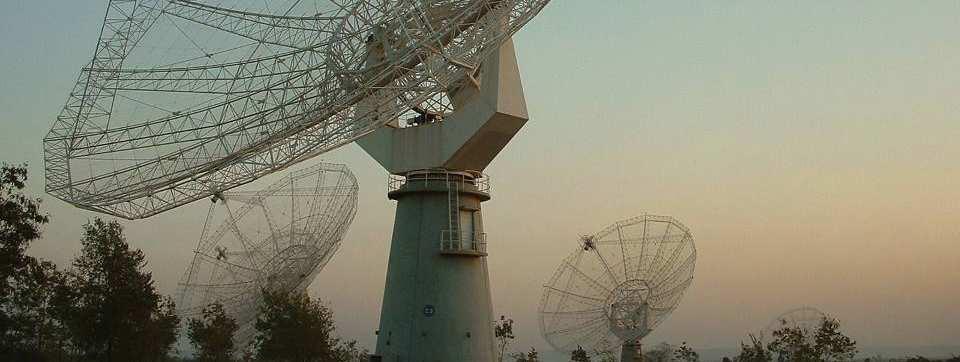
6 Giant MetrewaveRadio Telescope 6
7 GMRT -Introduction GMRT is a world class instrument for studying astrophysical phenomena at low radio frequencies (50 to 1450 MHz) Located 80 km north of Pune, 160 km east of Mumbai Array telescope consisting of 30 antennas of 45 metres diameter, operating at metre wavelengths -- the largest in the world at these frequencies 7
8 Overview of the GMRT 30 dishes, 45 m dia each 12 in a central 1 km x 1 km region 18 along 3 arms of Y-shaped array baselines : ~ 200 m to 30 km. Frequency bands: MHz MHz MHz MHz MHz max instantaneous processing BW = 32 MHz Effective collecting area (2-3% of SKA) : 30,000 sq m at lower frequencies 20,000 sq m at highest frequencies Supports 2 modes of operation : Interferometry, aperture synthesis Array mode (incoherent& coherent) 8


9 Aerial View of Central Square Antennas 9
10 GMRT antenna: Construction Stages 10
11 GMRT: Engineering Groups Mechanic al Frontend Backend GMRT Electrical & Civil Telemetry Servo 11
12 Organizational Hierarchy ( Scientific & Technical) Total scientific and technical staff strength :100+ Six Group Coordinators Scientific and Technical staff consists of Engineers, Technical Assistants, Lab Assistants, Scientific Officers and Telescope Operators. Short term positions Visiting Engineer, Trainee Engineer, STP students Dean (GMRT Observatory) Engineering Group Coordinators Technical Staff Scientific Staff 12


 Few arc min(> 20 kmph) 13 Alt-Azimuth")
13 GMRT antenna parameters Parameter Value Focal Length m Physical Aperture 1590 m2 f/d ratio Mounting Altitude Azimuth Elevation Limits 17 to 110 degrees Azimuth Range ± 270 degrees Slew Rates Alt 20 degree / min Az - 30 degree / min Weight of moving structure 82 tons + counter weight of 34 tons Survival wind speed 133 km/hour RMS surface error 10 mm (typical) Tracking and Pointing Error < 1 arc (up to 20 kmph) Few arc min(> 20 kmph) 13 Alt-Azimuth mount with ~3.5m dia azimuth bearing!
14 The Invisible Reflecting Surface 7% solidity with 0.55 mm diameter SS wires spot-welded at junction point to form a surface with 10x10 / 15x15/ 20x20 mm wire-grid. 14 Mesh panel supported by SS rope trusses attached to tubular parabolic frame: SMART concept to form the parabola.
15 The SMART concept The dish has 16 parabolic frames which give the basic shape The reflecting surface consists of a Stretched Mesh Attached to Rope Trusses The wire mesh size is matched to the shortest wavelengths of operation 15


16 GMRT Servo System Points the antennas to any part of the sky and tracks a source Being upgraded to brushless DC motors from brushed PMDC motors ± 270 movement around Az axis and 17 to 110 above horizon about elevation axis Slew speed of 30 / min in Az axis and 20 / min in El axis RMS tracking and Pointing accuracy: 1 arcmin at 20 kmph wind speed, 16


17 Servo Controller Pair of 6 HP DC servo motors in a counter-torque system for Azimuth and Elevation axes 17


18 Feed Positioning System Position Loop Control system with Incremental encoder for position feedback 8051 Microcontroller based system 0.5 hp DC servomotor Positioning Accuracy of 6 arc and Resolution of 1.05 arc Operating RF Frequency band of GMRT can be changed in about ONE MINUTE 18


19 Electrical Systems Power back-up (UPS and DG sets) to cover ALL the antennas Finding and eliminating sources of power-line interference Improved reliability of electrical sub-systems Approximate power consumption 20-25KWperantenna Uninterrupted power to all the laboratories and facilities in the central square campus 19
20 Radio Telescope Receiver 20
21 Radio Telescope Receiver Specifications IDEAL Radio Telescope Receiver: INFINITE bandwidth and ZERO noise PRACTICAL Radio Telescope: Parabolic Reflector Surface acts like a Low-Pass Filter due to surface errors and reflector dimensions (~ 2 GHz for GMRT) Internationally protected frequency bands For Spectral line observations For Continuum Observations Celestial signals are very weak measured in Jansky(Jy) (1 Jy= Wm -2 Hz -1 ) The input to the receiver (=ktb, ~ -100 dbm) must be amplified to around 0 dbm(=220 mv RMS) for processing by the digital electronics. Gain requirement of around 100 db (10 10 ) in the receiver chain The above gain must be distributed among various sub-systems with a good matching between Noise Figure Linear Dynamic Range Spurious Free Dynamic Range Ensure NO bottleneck is created by any Receiver stage! 21
22 Astronomical Signal Characteristics Zero mean Gaussian distributed random signal Binned Data Underlying Distribution Stationary random process mean and autocorrelation do not change with time (under ideal conditions) C o un t in B in Noise power measured over bandwidth P = ktb Watts Value


23 GMRT Receiver: Basic Block Diagram Each antenna has five wave bands, each having two polarization. Multi-frequency receiver uses low noise amplifiers and post amplification at the prime focus. Superheterodyne receiver: Converts RF to IF using phase coherent oscillators locked to stable GPS disciplined Rubidium clock reference. IF signals transported to the Central Station using fiber optic cables. IF signals conditioned and down-converted to base-band frequency. Signals are digitized and processed for computing visibilities, beam outputs and power spectra. Highly configurable receiver chain fully controllable from central station through telemetry system 23

24 Simplified Schematic of GMRT Receiver The Forward Broadcast optical fiber link sets the parameters and transfers LO Reference All LOs phase locked to a common stable frequency reference 24


25 Feeds of the GMRT Dual Polarized Primefocusfeedstocoverthe six bands of operation of GMRT Dual Frequency operation in 233 and 610 MHz bands MatchedEandHplane patterns with ~10 db edge-taper and ~20% bandwidth Feeds convert EM energy to electrical signal 25
26 Operating Frequencies of the GMRT MHz MHz MHz MHz MHz MHz 325 MHz Antenna primary feeds are placed on a rotating turret near the focus of the dish 235 / 610 MHz 150 MHz 26
27 GMRT Front-end ~60 db gain provided by the front end system Receiver temperature varies from 260 K (150 MHz) to 45 K (1400 MHz) 27
 is used for installing and")
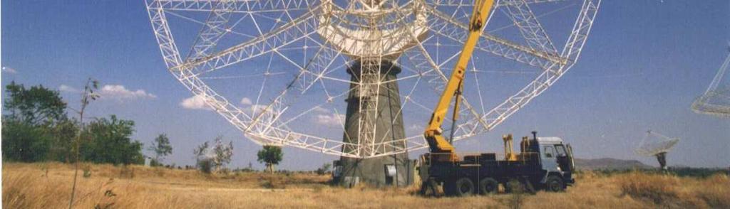
28 Installing and Servicing 28 High-lift platform (aka cherry picker) is used for installing and servicing feeds and front end electronics. Itisalsousedforpainting,FPSandstructuralmaintenanceoftheantenna.


29 Signal Processing in IF systems Conversion of RF to commonifof70mhz SAW (Surface Acoustic Wave) filters used for band shapingofsignalsat70mhz IF signals are up-converted to 130 MHz and 175 MHz for Ch-1 and 2 respectively for transmission over optical fiber link High dynamic range ALC circuits are used before the signal is given to OF Transmitter to maintain a constant power. IF system installation at antenna base 29
30 30


31 Signal Processing in Base-band System Converts IF Frequency signals to baseband frequency of 32 MHz. 30to1monitoringatCentral station for live checking of quality of signal from antennas. 31
32 Signal Processing Preliminaries -1 In order to reconstruct a sampled signal, the sampling frequency must be twice the maximum frequency of the signal (or the bandwidth), a.k.a. Nyquist theorem f s = 2f m The spectral resolution f r (width of a spectral channel) is dependent of the number of FFT points (N) and the bandwidth ( f) f r = f / N Fouriertransformofarealsignalisconjugatesymmetric-i.e.fora N-point FFT, only half the number of spectral channels have unique information 32
33 Signal Processing Preliminaries -2 Shift in time-domain (time delay) is phase shift in the frequency domain Convolution in time domain is multiplication in the frequency domain Correlation is a measure of similarity between the two signals and it varies as a function of the lag between them. Even function, peaks at zero lag, reduces linearly as a function of lag Shows the degree of similarity between the signals Correlated (1), Uncorrelated (0), Partially correlated (0<R<1), Anticorrelated (-1) 33


34 Digital Backend Signal Processing Imaging Mode Beam Mode 34


35 GMRT Software Backend (GSB) 32 antennas 32 MHz bandwidth, dual polarization Net input data rate : 2 Gsamples/sec FX correlator+ beam former + pulsar receiver Uses off-the-shelf ADC cards, CPUs & network switches to implement a fully real-time backend 35
36 Final Outcome from the receiver chain 36 Self spectra of two GMRT antennas at 1.4 to 1.2 GHz RF on source 3C286, Spectral channels :2048, Integration time : 0.671s


37 Final Outcome from the receiver chain 37 Cross correlation and phase spectrum of two GMRT antennas at 1.4 to 1.2 GHz RF on source 3C286, Spectral channels :2048, Integration time : 0.671s
38 The ugmrt 38
39 The Upgraded GMRT (ugmrt) AmajorupgradeisunderwaynowattheGMRTwithfocuson: Seamless frequency coverage from ~30 MHz to 1500 MHz-> design of new feeds and receiver system Improved G/T sys by reduced system temperature -> better technology receivers Increased instantaneous bandwidth of 400 MHz (from the present maximum of 32 MHz) -> modern new digital back-end receiver Revamped servo system for the antennas Modern and versatile control and monitoring system Matching improvements in offline computing facilities and other infrastructure Improvements in mechanical systems and infrastructure facilities 39
40 Features : Comparison with Current System 40 Current system Supports observation at specific frequency bands in 50 to 1500 MHz. Instantaneous bandwidth of 32 MHz in each polarization. Facility for dual frequency observations with 32 MHz in each band. Low dynamic range & RFI rejection capabilities. Power Level monitoring available atfewstagesinthereceiverchain. Upgraded system Seamless Coverage from 30 to 1500 MHz. Supports instantaneous bandwidth of 400 MHz in each polarization. Possible only if the frequency bands are within same feed bandwidth. Improved dynamic range and inbuilt RFI cancellation scheme. Integrated Power Level Monitoring Circuits for easy trouble shooting.

 41 Expected sensitivity of the")

41 Benefits of ugmrt First light results: spectral lines from different sources, at different parts of the MHz band (courtesy : Nissim Kanekar ) 41 Expected sensitivity of the ugmrt compared to other major facilities in the world, present and projected (courtesy : Nissim Kanekar)
 1553.")
 Fiber link 22.9 km 1551.")
 ORX 1550.11 nm OTX 1548.51 nm (193.")

42 Components of Upgraded GMRT Frontend nm (193.0 THz) nm MHz feed nm (193.2 THz) Fiber link 22.9 km nm MHz LNA OTX nm (193.4 THz) ORX nm OTX nm (193.6 THz) ORX nm DWDM Multiplexer At ANTENNA Base DWDM de-multiplexer at CEB MHz feed CASPER 500 MHz Meet 2013 feed

43 ugmrtreceiver Block Diagram New feeds with wider frequency coverage allowing observations from 50 to1500mhzband Improved front-end electronics with low noise and increased dynamic range RF signal is directly transported to the central station using a broadband analog fiber Reduced electronics at antenna sites 43
44 Upgraded Fiber Optic System GMRT is the first radio telescope to use analog fiber optic link for signal transport. Fiberisburiedatadepth of1.5mbelowtheground to reduce the effect of temperature on phase stability of the link. Link distances vary from 200mto22km. Uses wavelength division multiplexing to accommodate multiple data and control channels onasinglefiber. 44 LASER Transmitter, Optical Multiplexer, Optical receiver DWDM based system


45 Upgraded Backend -Schematic Most of the signal processing in backend receiver chain is carried out at the central station Analog Processing Digitization Digital Processing RFI Excision Signal Monitoring 45
46 Digital Backend using FPGAs and GPUs 46
47 ROACH Board 47 Image Courtesy: CASPER

48 GMRT Wideband Digital Backend GMRT Wideband Digital Backend for processing 16 antenna dual polarization 400 MHz using FPGAs and GPUs 48
49 Upgraded Telemetry System New station control computer Ethernet link from central station to each antenna, via the optical fiber New generation monitor and control modules using modern microcontroller Improved control room software running on Linux platform 49
50 Results from the ugmrt 3C285 observed for about 3 hours using 11 broadband antennas, 300 MHz RF, 200 MHz bandwidth, 2048 spectral channels. RMS noise: 0.6 mjy, ~5.4 arcsec resolution 50 Image Courtesy: DharamVir Lal
51 Biggest Challenge for Contemporary Radio Telescopes 51
52 Radio Frequency Interference Man-made electromagnetic radiation from electronic/electrical equipments RFI is typically 30 to 40 db (i.e to times) stronger than astronomical signal RFI has a non-random distribution RFI mitigation very important problem (challenge) for contemporary radio telescopes 52


53 Typical Sources of RFI at GMRT Broadband RFI Narrowband RFI Sparking 53 Image Courtesy: Wikipedia
54 Acknowledgements I would like to thank the following colleagues at GMRT & NCRA for their help in this presentation and related technical discussions Yashwant Gupta Ajith Kumar B. Divya Oberoi Sanjeet Rai Gaurav Parikh Amit Kumar A.K. Nandi DharamVir Lal 54

55 Thank You! 55
Real-time RFI Mitigation for the Upgraded GMRT
 Real-time RFI Mitigation for the Upgraded GMRT Kaushal D. Buch Digital Backend Group, Giant Metrewave Radio Telescope, NCRA-TIFR, Pune, India kdbuch@gmrt.ncra.tifr.res.in The (Upgraded) GMRT Giant Metrewave
Focal Plane Array Beamformer for the Expanded GMRT: Initial
 Focal Plane Array Beamformer for the Expanded GMRT: Initial Implementation on ROACH Kaushal D. Buch Digital Backend Group, Giant Metrewave Radio Telescope, NCRA-TIFR, Pune, India kdbuch@gmrt.ncra.tifr.res.in
The GMRT : a look at the Past, Present and Future
 The GMRT : a look at the Past, Present and Future Yashwant Gupta & Govind Swarup National Centre for Radio Astrophysics Pune India URSI GASS Montreal 2017 The GMRT : a look at the Past, Present and Future
The GMRT: System Parameters and Current Status
 The GMRT: System Parameters and Current Status Last updated : 15 June 2018 Contents 1 General Overview 2 1.1 Antennas & Feeds................................. 2 1.2 Receiver Electronics................................
Introduction to Radio Astronomy!
 Introduction to Radio Astronomy! Sources of radio emission! Radio telescopes - collecting the radiation! Processing the radio signal! Radio telescope characteristics! Observing radio sources Sources of
External sources of RFI at the GMRT: Methods for control and co-existence with commercial users
 External sources of RFI at the GMRT: Methods for control and co-existence with commercial users Pravin Ashok Raybole 1 GMRT-NCRA-TIFR P.O Box No. 6, Narayangon, Pune, India. E-mail: pravin@gmrt.ncra.tifr.res.in
EVLA Memo 105. Phase coherence of the EVLA radio telescope
 EVLA Memo 105 Phase coherence of the EVLA radio telescope Steven Durand, James Jackson, and Keith Morris National Radio Astronomy Observatory, 1003 Lopezville Road, Socorro, NM, USA 87801 ABSTRACT The
INTERFEROMETRY: II Nissim Kanekar (NCRA TIFR)
") INTERFEROMETRY: II Nissim Kanekar (NCRA TIFR) WSRT GMRT VLA ATCA ALMA SKA MID PLAN Introduction. The van Cittert Zernike theorem. A 2 element interferometer. The fringe pattern. 2 D and 3 D interferometers.
INTERFEROMETRY: II Nissim Kanekar (NCRA TIFR) WSRT GMRT VLA ATCA ALMA SKA MID PLAN Introduction. The van Cittert Zernike theorem. A 2 element interferometer. The fringe pattern. 2 D and 3 D interferometers.
Holography Transmitter Design Bill Shillue 2000-Oct-03
 Holography Transmitter Design Bill Shillue 2000-Oct-03 Planned Photonic Reference Distribution for Test Interferometer The transmitter for the holography receiver is made up mostly of parts that are already
Phased Array Feeds A new technology for multi-beam radio astronomy
 Phased Array Feeds A new technology for multi-beam radio astronomy Aidan Hotan ASKAP Deputy Project Scientist 2 nd October 2015 CSIRO ASTRONOMY AND SPACE SCIENCE Outline Review of radio astronomy concepts.
Phased Array Feeds A new technology for wide-field radio astronomy
 Phased Array Feeds A new technology for wide-field radio astronomy Aidan Hotan ASKAP Project Scientist 29 th September 2017 CSIRO ASTRONOMY AND SPACE SCIENCE Outline Review of radio astronomy concepts
Towards SKA Multi-beam concepts and technology
 Towards SKA Multi-beam concepts and technology SKA meeting Meudon Observatory, 16 June 2009 Philippe Picard Station de Radioastronomie de Nançay philippe.picard@obs-nancay.fr 1 Square Kilometre Array:
Fundamentals of Radio Interferometry
 Fundamentals of Radio Interferometry Rick Perley, NRAO/Socorro Fourteenth NRAO Synthesis Imaging Summer School Socorro, NM Topics Why Interferometry? The Single Dish as an interferometer The Basic Interferometer
Integrated receivers for mid-band SKA. Suzy Jackson Engineer, Australia Telescope National Facility
 Integrated receivers for mid-band SKA Suzy Jackson Engineer, Australia Telescope National Facility ASKAP/SKA Special Technical Brief 23 rd October, 2009 Talk overview Mid band SKA receiver challenges ASKAP
IF/LO Systems for Single Dish Radio Astronomy Centimeter Wave Receivers
 IF/LO Systems for Single Dish Radio Astronomy Centimeter Wave Receivers Lisa Wray NAIC, Arecibo Observatory Abstract. Radio astronomy receivers designed to detect electromagnetic waves from faint celestial
Guide to observation planning with GREAT
 Guide to observation planning with GREAT G. Sandell GREAT is a heterodyne receiver designed to observe spectral lines in the THz region with high spectral resolution and sensitivity. Heterodyne receivers
Submillimeter (continued)
") Submillimeter (continued) Dual Polarization, Sideband Separating Receiver Dual Mixer Unit The 12-m Receiver Here is where the receiver lives, at the telescope focus Receiver Performance T N (noise temperature)
Submillimeter (continued) Dual Polarization, Sideband Separating Receiver Dual Mixer Unit The 12-m Receiver Here is where the receiver lives, at the telescope focus Receiver Performance T N (noise temperature)
November SKA Low Frequency Aperture Array. Andrew Faulkner
 SKA Phase 1 Implementation Southern Africa Australia SKA 1 -mid 250 15m dia. Dishes 0.4-3GHz SKA 1 -low 256,000 antennas Aperture Array Stations 50 350/650MHz SKA 1 -survey 90 15m dia. Dishes 0.7-1.7GHz
Smart Antennas in Radio Astronomy
 Smart Antennas in Radio Astronomy Wim van Cappellen cappellen@astron.nl Netherlands Institute for Radio Astronomy Our mission is to make radio-astronomical discoveries happen ASTRON is an institute for
G. Serra.
 G. Serra gserra@oa-cagliari.inaf.it on behalf of Metrology team* *T. Pisanu, S. Poppi, F.Buffa, P. Marongiu, R. Concu, G. Vargiu, P. Bolli, A. Saba, M.Pili, E.Urru Astronomical Observatory of Cagliari
Receiver Performance and Comparison of Incoherent (bolometer) and Coherent (receiver) detection
 and Coherent (receiver) detection") At ev gap /h the photons have sufficient energy to break the Cooper pairs and the SIS performance degrades. Receiver Performance and Comparison of Incoherent (bolometer) and Coherent (receiver) detection
At ev gap /h the photons have sufficient energy to break the Cooper pairs and the SIS performance degrades. Receiver Performance and Comparison of Incoherent (bolometer) and Coherent (receiver) detection
A Crash Course in Radio Astronomy and Interferometry: 1. Basic Radio/mm Astronomy
 A Crash Course in Radio Astronomy and Interferometry: 1. Basic Radio/mm Astronomy James Di Francesco National Research Council of Canada North American ALMA Regional Center Victoria (thanks to S. Dougherty,
Antennas. Greg Taylor. University of New Mexico Spring Astronomy 423 at UNM Radio Astronomy
 Antennas Greg Taylor University of New Mexico Spring 2017 Astronomy 423 at UNM Radio Astronomy Outline 2 Fourier Transforms Interferometer block diagram Antenna fundamentals Types of antennas Antenna performance
Specifications for the GBT spectrometer
 GBT memo No. 292 Specifications for the GBT spectrometer Authors: D. Anish Roshi 1, Green Bank Scientific Staff, J. Richard Fisher 2, John Ford 1 Affiliation: 1 NRAO, Green Bank, WV 24944. 2 NRAO, Charlottesville,
Active Impedance Matched Dual-Polarization Phased Array Feed for the GBT
 Active Impedance Matched Dual-Polarization Phased Array Feed for the GBT Karl F. Warnick, David Carter, Taylor Webb, Brian D. Jeffs Department of Electrical and Computer Engineering Brigham Young University,
Antennas. Greg Taylor. University of New Mexico Spring Astronomy 423 at UNM Radio Astronomy
 Antennas Greg Taylor University of New Mexico Spring 2011 Astronomy 423 at UNM Radio Astronomy Radio Window 2 spans a wide range of λ and ν from λ ~ 0.33 mm to ~ 20 m! (ν = 1300 GHz to 15 MHz ) Outline
Radio Interferometers Around the World. Amy J. Mioduszewski (NRAO)
") Radio Interferometers Around the World Amy J. Mioduszewski (NRAO) A somewhat biased view of current interferometers Limited to telescopes that exist or are in the process of being built (i.e., I am not
Radio Interferometers Around the World Amy J. Mioduszewski (NRAO) A somewhat biased view of current interferometers Limited to telescopes that exist or are in the process of being built (i.e., I am not
THE KAROO ARRAY TELESCOPE (KAT) & FPA EFFORT IN SOUTH AFRICA
 & FPA EFFORT IN SOUTH AFRICA") THE KAROO ARRAY TELESCOPE (KAT) & FPA EFFORT IN SOUTH AFRICA Dr. Dirk Baker (KAT FPA Sub-system Manager) Prof. Justin Jonas (SKA SA Project Scientist) Ms. Anita Loots (KAT Project Manager) Mr. David de
THE KAROO ARRAY TELESCOPE (KAT) & FPA EFFORT IN SOUTH AFRICA Dr. Dirk Baker (KAT FPA Sub-system Manager) Prof. Justin Jonas (SKA SA Project Scientist) Ms. Anita Loots (KAT Project Manager) Mr. David de
Memo 65 SKA Signal processing costs
 Memo 65 SKA Signal processing costs John Bunton, CSIRO ICT Centre 12/08/05 www.skatelescope.org/pages/page_memos.htm Introduction The delay in the building of the SKA has a significant impact on the signal
Introduction to Interferometry. Michelson Interferometer. Fourier Transforms. Optics: holes in a mask. Two ways of understanding interferometry
 Introduction to Interferometry P.J.Diamond MERLIN/VLBI National Facility Jodrell Bank Observatory University of Manchester ERIS: 5 Sept 005 Aim to lay the groundwork for following talks Discuss: General
Sideband Smear: Sideband Separation with the ALMA 2SB and DSB Total Power Receivers
 and DSB Total Power Receivers SCI-00.00.00.00-001-A-PLA Version: A 2007-06-11 Prepared By: Organization Date Anthony J. Remijan NRAO A. Wootten T. Hunter J.M. Payne D.T. Emerson P.R. Jewell R.N. Martin
To print higher-resolution math symbols, click the Hi-Res Fonts for Printing button on the jsmath control panel.
 To print higher-resolution math symbols, click the Hi-Res Fonts for Printing button on the jsmath control panel. Radiometers Natural radio emission from the cosmic microwave background, discrete astronomical
Radio Interferometry. Xuening Bai. AST 542 Observational Seminar May 4, 2011
 Radio Interferometry Xuening Bai AST 542 Observational Seminar May 4, 2011 Outline Single-dish radio telescope Two-element interferometer Interferometer arrays and aperture synthesis Very-long base line
Phased Array Feeds & Primary Beams
 Phased Array Feeds & Primary Beams Aidan Hotan ASKAP Deputy Project Scientist 3 rd October 2014 CSIRO ASTRONOMY AND SPACE SCIENCE Outline Review of parabolic (dish) antennas. Focal plane response to a
Integrated receivers for mid-band SKA. Suzy Jackson Engineer, Australia Telescope National Facility
 Integrated receivers for mid-band SKA Suzy Jackson Engineer, Australia Telescope National Facility SKADS FP6 Meeting Chateau de Limelette 4-6 November, 2009 Talk overview Mid band SKA receiver challenges
Correlator Development at Haystack. Roger Cappallo Haystack-NRAO Technical Mtg
 Correlator Development at Haystack Roger Cappallo Haystack-NRAO Technical Mtg. 2006.10.26 History of Correlator Development at Haystack ~1973 Mk I 360 Kb/s x 2 stns. 1981 Mk III 112 Mb/s x 4 stns. 1986
Simulation of Pair of 150MHz Thick Folded Dipole. Using WIPL-D 3D EM Solver
 Simulation of Pair of 150MHz Thick Folded Dipole Using WIPL-D 3D EM Solver Internal Technical Report November 2008 B. Hanumanth Rao G. Sankar Gaint Meterwave Radio Telescope National Center for Radio Astrophysics
ATCA Antenna Beam Patterns and Aperture Illumination
 1 AT 39.3/116 ATCA Antenna Beam Patterns and Aperture Illumination Jared Cole and Ravi Subrahmanyan July 2002 Detailed here is a method and results from measurements of the beam characteristics of the
Wide-Band Imaging. Outline : CASS Radio Astronomy School Sept 2012 Narrabri, NSW, Australia. - What is wideband imaging?
 Wide-Band Imaging 24-28 Sept 2012 Narrabri, NSW, Australia Outline : - What is wideband imaging? - Two Algorithms Urvashi Rau - Many Examples National Radio Astronomy Observatory Socorro, NM, USA 1/32
Fundamentals of Radio Interferometry. Robert Laing (ESO)
") Fundamentals of Radio Interferometry Robert Laing (ESO) 1 ERIS 2015 Objectives A more formal approach to radio interferometry using coherence functions A complementary way of looking at the technique Simplifying
Fundamentals of Radio Interferometry Robert Laing (ESO) 1 ERIS 2015 Objectives A more formal approach to radio interferometry using coherence functions A complementary way of looking at the technique Simplifying
Antennas & Receivers in Radio Astronomy
 Antennas & Receivers in Radio Astronomy Mark McKinnon Fifteenth Synthesis Imaging Workshop 1-8 June 2016 Purpose & Outline Purpose: describe how antenna elements can affect the quality of images produced
TSEK02: Radio Electronics Lecture 6: Propagation and Noise. Ted Johansson, EKS, ISY
 TSEK02: Radio Electronics Lecture 6: Propagation and Noise Ted Johansson, EKS, ISY 2 Propagation and Noise - Channel and antenna: not in the Razavi book - Noise: 2.3 The wireless channel The antenna Signal
RFI: Sources, Identification, Mitigation. Ganesh Rajagopalan & Mamoru Sekido & Brian Corey
 RFI: Sources, Identification, Mitigation Ganesh Rajagopalan & Mamoru Sekido & Brian Corey 1 Effects of RFI on VLBI RFI increases system temperature. Depending on strength of RFI, it may affect only those
Introduction to Radio Astronomy
 Introduction to Radio Astronomy The Visible Sky, Sagittarius Region 2 The Radio Sky 3 4 Optical and Radio can be done from the ground! 5 Outline The Discovery of Radio Waves Maxwell, Hertz and Marconi
Figure 1 Photo of an Upgraded Low Band Receiver
 NATIONAL RADIO ASTRONOMY OBSERVATORY SOCORRO, NEW MEXICO EVLA TECHNICAL REPORT #175 LOW BAND RECEIVER PERFORMANCE SEPTMBER 27, 2013 S.DURAND, P.HARDEN Upgraded low band receivers, figure 1, were installed
Antennas and Receivers in Radio Astronomy
 Antennas and Receivers in Radio Astronomy Mark McKinnon Eleventh Synthesis Imaging Workshop Socorro, June 10-17, 2008 Outline 2 Context Types of antennas Antenna fundamentals Reflector antennas Mounts
Allen Telescope Array & Radio Frequency Interference. Geoffrey C. Bower UC Berkeley
 Allen Telescope Array & Radio Frequency Interference Geoffrey C. Bower UC Berkeley Allen Telescope Array Large N design 350 x 6.1m antennas Sensitivity of the VLA Unprecedented imaging capabilities Continuous
Fundamentals of the GBT and Single-Dish Radio Telescopes Dr. Ron Maddalena
 Fundamentals of the GB and Single-Dish Radio elescopes Dr. Ron Maddalena March 2016 Associated Universities, Inc., 2016 National Radio Astronomy Observatory Green Bank, WV National Radio Astronomy Observatory
Radio Astronomy: SKA-Era Interferometry and Other Challenges. Dr Jasper Horrell, SKA SA (and Dr Oleg Smirnov, Rhodes and SKA SA)
") Radio Astronomy: SKA-Era Interferometry and Other Challenges Dr Jasper Horrell, SKA SA (and Dr Oleg Smirnov, Rhodes and SKA SA) ASSA Symposium, Cape Town, Oct 2012 Scope SKA antenna types Single dishes
Radio Astronomy: SKA-Era Interferometry and Other Challenges Dr Jasper Horrell, SKA SA (and Dr Oleg Smirnov, Rhodes and SKA SA) ASSA Symposium, Cape Town, Oct 2012 Scope SKA antenna types Single dishes
Space Frequency Coordination Group
 Space Frequency Coordination Group Report SFCG 38-1 POTENTIAL RFI TO EESS (ACTIVE) CLOUD PROFILE RADARS IN 94.0-94.1 GHZ FREQUENCY BAND FROM OTHER SERVICES Abstract This new SFCG report analyzes potential
Very Long Baseline Interferometry
 Very Long Baseline Interferometry Cormac Reynolds, JIVE European Radio Interferometry School, Bonn 12 Sept. 2007 VLBI Arrays EVN (Europe, China, South Africa, Arecibo) VLBA (USA) EVN + VLBA coordinate
More Radio Astronomy
 More Radio Astronomy Radio Telescopes - Basic Design A radio telescope is composed of: - a radio reflector (the dish) - an antenna referred to as the feed on to which the radiation is focused - a radio
Introduction to Radioastronomy: Interferometers and Aperture Synthesis
 Introduction to Radioastronomy: Interferometers and Aperture Synthesis J.Köppen joachim.koppen@astro.unistra.fr http://astro.u-strasbg.fr/~koppen/jkhome.html Problem No.2: Angular resolution Diffraction
Introduction to interferometry with bolometers: Bob Watson and Lucio Piccirillo
 Introduction to interferometry with bolometers: Bob Watson and Lucio Piccirillo Paris, 19 June 2008 Interferometry (heterodyne) In general we have i=1,...,n single dishes (with a single or dual receiver)
Casper Instrumentation at Green Bank
 Casper Instrumentation at Green Bank John Ford September 28, 2009 The NRAO is operated for the National Science Foundation (NSF) by Associated Universities, Inc. (AUI), under a cooperative agreement. GBT
Observing Modes and Real Time Processing
 2010-11-30 Observing with ALMA 1, Observing Modes and Real Time Processing R. Lucas November 30, 2010 Outline 2010-11-30 Observing with ALMA 2, Observing Modes Interferometry Modes Interferometry Calibrations
Aperture Antennas. Reflectors, horns. High Gain Nearly real input impedance. Huygens Principle
 Antennas 97 Aperture Antennas Reflectors, horns. High Gain Nearly real input impedance Huygens Principle Each point of a wave front is a secondary source of spherical waves. 97 Antennas 98 Equivalence
Practicalities of Radio Interferometry
 Practicalities of Radio Interferometry Rick Perley, NRAO/Socorro 13 th Synthesis Imaging Summer School 29 May 5 June, 2012 Socorro, NM Topics Practical Extensions to the Theory: Finite bandwidth Rotating
Extra slides. 10/05/2011 SAC meeting IRAM Grenoble 1
 Extra slides 10/05/2011 SAC meeting IRAM Grenoble 1 New NIKA spectral responses Bands spectral response obtained with a Martin-Puplett interferometer 10/05/2011 SAC meeting IRAM Grenoble 2 New NIKA backend
Introduction to Radio Astronomy. Richard Porcas Max-Planck-Institut fuer Radioastronomie, Bonn
 Introduction to Radio Astronomy Richard Porcas Max-Planck-Institut fuer Radioastronomie, Bonn 1 Contents Radio Waves Radio Emission Processes Radio Noise Radio source names and catalogues Radio telescopes
Performance of the Prototype NLC RF Phase and Timing Distribution System *
 SLAC PUB 8458 June 2000 Performance of the Prototype NLC RF Phase and Timing Distribution System * Josef Frisch, David G. Brown, Eugene Cisneros Stanford Linear Accelerator Center, Stanford University,
TSEK02: Radio Electronics Lecture 6: Propagation and Noise. Ted Johansson, EKS, ISY
 TSEK02: Radio Electronics Lecture 6: Propagation and Noise Ted Johansson, EKS, ISY 2 Propagation and Noise - Channel and antenna: not in the Razavi book - Noise: 2.3 The wireless channel The antenna Signal
THE SHIPBOARD ANTENNA TRACKING SYSTEM OF TELEMETRY
 THE SHIPBOARD ANTENNA TRACKING SYSTEM OF TELEMETRY Gao Quan Hui Principal engineer Beijing Research Institute Of Telemetry Beijing, P. R. China ABSTRACT This paper describes a C band auto tracking receiving
KULLIYYAH OF ENGINEERING
 KULLIYYAH OF ENGINEERING DEPARTMENT OF ELECTRICAL & COMPUTER ENGINEERING ANTENNA AND WAVE PROPAGATION LABORATORY (ECE 4103) EXPERIMENT NO 3 RADIATION PATTERN AND GAIN CHARACTERISTICS OF THE DISH (PARABOLIC)
Cross Correlators. Jayce Dowell/Greg Taylor. University of New Mexico Spring Astronomy 423 at UNM Radio Astronomy
 Cross Correlators Jayce Dowell/Greg Taylor University of New Mexico Spring 2017 Astronomy 423 at UNM Radio Astronomy Outline 2 Re-cap of interferometry What is a correlator? The correlation function Simple
UHF Phased Array Ground Stations for Cubesat Applications
 UHF Phased Array Ground Stations for Cubesat Applications Colin Sheldon, Justin Bradfield, Erika Sanchez, Jeffrey Boye, David Copeland and Norman Adams 10 August 2016 Colin Sheldon, PhD 240-228-8519 Colin.Sheldon@jhuapl.edu
Chapter 3. Instrumentation. 3.1 Telescope Site Layout. 3.2 Telescope Optics
 Chapter 3 Instrumentation 3.1 Telescope Site Layout The 12m is located on the southwest ridge of Kitt Peak, about two miles below the top of the mountain. Other telescopes on the southwest ridge are the
Planning (VLA) observations
 observations") Planning () observations 14 th Synthesis Imaging Workshop (May 2014) Loránt Sjouwerman National Radio Astronomy Observatory (Socorro, NM) Atacama Large Millimeter/submillimeter Array Karl G. Jansky Very
Planning () observations 14 th Synthesis Imaging Workshop (May 2014) Loránt Sjouwerman National Radio Astronomy Observatory (Socorro, NM) Atacama Large Millimeter/submillimeter Array Karl G. Jansky Very
Signal Flow & Radiometer Equation. Aletha de Witt AVN-Newton Fund/DARA 2018 Observational & Technical Training HartRAO
 Signal Flow & Radiometer Equation Aletha de Witt AVN-Newton Fund/DARA 2018 Observational & Technical Training HartRAO Understanding Radio Waves The meaning of radio waves How radio waves are created -
ANTENNA INTRODUCTION / BASICS
 ANTENNA INTRODUCTION / BASICS RULES OF THUMB: 1. The Gain of an antenna with losses is given by: 2. Gain of rectangular X-Band Aperture G = 1.4 LW L = length of aperture in cm Where: W = width of aperture
William Stallings Data and Computer Communications 7 th Edition. Chapter 4 Transmission Media
 William Stallings Data and Computer Communications 7 th Edition Chapter 4 Transmission Media Overview Guided - wire Unguided - wireless Characteristics and quality determined by medium and signal For guided,
OPTICS OF SINGLE BEAM, DUAL BEAM & ARRAY RECEIVERS ON LARGE TELESCOPES J A M E S W L A M B, C A L T E C H
 OPTICS OF SINGLE BEAM, DUAL BEAM & ARRAY RECEIVERS ON LARGE TELESCOPES J A M E S W L A M B, C A L T E C H OUTLINE Antenna optics Aberrations Diffraction Single feeds Types of feed Bandwidth Imaging feeds
GBT Spectral Baseline Investigation Rick Fisher, Roger Norrod, Dana Balser (G. Watts, M. Stennes)
") GBT Spectral Baseline Investigation Rick Fisher, Roger Norrod, Dana Balser (G. Watts, M. Stennes) Points to Note: Wider bandwidths than were used on 140 Foot Cleaner antenna so other effects show up Larger
GBT Spectral Baseline Investigation Rick Fisher, Roger Norrod, Dana Balser (G. Watts, M. Stennes) Points to Note: Wider bandwidths than were used on 140 Foot Cleaner antenna so other effects show up Larger
RANGE resolution and dynamic range are the most important
 INTL JOURNAL OF ELECTRONICS AND TELECOMMUNICATIONS, 2012, VOL. 58, NO. 2, PP. 135 140 Manuscript received August 17, 2011; revised May, 2012. DOI: 10.2478/v10177-012-0019-1 High Resolution Noise Radar
May AA Communications. Portugal
 SKA Top-level description A large radio telescope for transformational science Up to 1 million m 2 collecting area Operating from 70 MHz to 10 GHz (4m-3cm) Two or more detector technologies Connected to
(The basics of) VLBI Basics. Pedro Elosegui MIT Haystack Observatory. With big thanks to many of you, here and out there
 VLBI Basics. Pedro Elosegui MIT Haystack Observatory. With big thanks to many of you, here and out there") (The basics of) VLBI Basics Pedro Elosegui MIT Haystack Observatory With big thanks to many of you, here and out there Some of the Points Will Cover Today Geodetic radio telescopes VLBI vs GPS concept
(The basics of) VLBI Basics Pedro Elosegui MIT Haystack Observatory With big thanks to many of you, here and out there Some of the Points Will Cover Today Geodetic radio telescopes VLBI vs GPS concept
The Sardinia Radio Telescope conversion, distribution, and receiver control system
 Mem. S.A.It. Suppl. Vol. 10, 66 c SAIt 2006 Memorie della Supplementi The Sardinia Radio Telescope conversion, distribution, and receiver control system J. Monari, A. Orfei, A. Scalambra, S. Mariotti,
Recent progress and future development of Nobeyama 45-m Telescope
 Recent progress and future development of Nobeyama 45-m Telescope Masao Saito: Director of Nobeyama Radio Observatory Tetsuhiro Minamidani: Nobeyama Radio Observatory Outline Nobeyama 45-m Telescope Recent
A High-Speed Data Downlink for Wide-Bandwidth CubeSat Payloads
 A High-Speed Data Downlink for Wide-Bandwidth CubeSat Payloads John Buonocore 12 th Annual Developer s Workshop 22 April 2015 Cal Poly San Luis Obispo High Speed Data Downlink The need for wider bandwidth
Array noise temperature measurements at the Parkes PAF Test-bed Facility
 Array noise temperature measurements at the Parkes PAF Test-bed Facility Douglas B. Hayman, Aaron P. Chippendale, Robert D. Shaw and Stuart G. Hay MIDPREP 1 April 2014 COMPUTATIONAL INFORMATICS ASTRONOMY
March Phased Array Technology. Andrew Faulkner
 Aperture Arrays Michael Kramer Sparse Type of AA selection 1000 Sparse AA-low Sky Brightness Temperature (K) 100 10 T sky A eff Fully sampled AA-mid Becoming sparse Aeff / T sys (m 2 / K) Dense A eff /T
PoS(11th EVN Symposium)113
113") High-order sampling technique for geodetic VLBI and the future National Institute of Information and Communications Technology, 893-1 Hirai, Kashima, Ibaraki 314-8501, Japan E-mail: takefuji@nict.go.jp
High-order sampling technique for geodetic VLBI and the future National Institute of Information and Communications Technology, 893-1 Hirai, Kashima, Ibaraki 314-8501, Japan E-mail: takefuji@nict.go.jp
ARTEMIS: Low-Cost Ground Station Antenna Arrays for Microspacecraft Mission Support. G. James Wells Mark A. Sdao Robert E. Zee
 ARTEMIS: Low-Cost Ground Station Antenna Arrays for Microspacecraft Mission Support G. James Wells Mark A. Sdao Robert E. Zee Space Flight Laboratory University of Toronto Institute for Aerospace Studies
SMA Technical Memo 147 : 08 Sep 2002 HOLOGRAPHIC SURFACE QUALITY MEASUREMENTS OF THE SUBMILLIMETER ARRAY ANTENNAS
 SMA Technical Memo 147 : 08 Sep 2002 HOLOGRAPHIC SURFACE QUALITY MEASUREMENTS OF THE SUBMILLIMETER ARRAY ANTENNAS T. K. Sridharan, M. Saito, N. A. Patel Harvard-Smithsonian Center for Astrophysics 60 Garden
Multi-octave radio frequency systems: Developments of antenna technology in radio astronomy and imaging systems
 Multi-octave radio frequency systems: Developments of antenna technology in radio astronomy and imaging systems Professor Tony Brown School of Electrical and Electronic Engineering University of Manchester
Commissioning Report for the ATCA L/S Receiver Upgrade Project
 Commissioning Report for the ATCA L/S Receiver Upgrade Project N. M. McClure-Griffiths, J. B. Stevens, & S. P. O Sullivan 8 June 211 1 Introduction The original Australia Telescope Compact Array (ATCA)
Antenna and Analog Beamformer
 Antenna and Analog Beamformer Requirements The antenna system is responsible for collecting radiation from the sky and presenting a suitably conditioned 80-300 MHz RF signal to the receiver node. Because
Instrument Requirements and Options for Meeting the Science Opportunities MHz P. Dewdney A. Gray, B. Veidt
 Instrument Requirements and Options for Meeting the Science Opportunities 300-3000 MHz P. Dewdney A. Gray, B. Veidt Dominion Radio Astrophysical Observatory Herzberg Institute of Astrophysics National
EVLA Memo #166 Comparison of the Performance of the 3-bit and 8-bit Samplers at C (4 8 GHz), X (8 12 GHz) and Ku (12 18 GHz) Bands
, X (8 12 GHz) and Ku (12 18 GHz) Bands") EVLA Memo #166 Comparison of the Performance of the 3-bit and 8-bit Samplers at C (4 8 GHz), X (8 12 GHz) and Ku (12 18 GHz) Bands E. Momjian and R. Perley NRAO March 27, 2013 Abstract We present sensitivity
EVLA Memo #166 Comparison of the Performance of the 3-bit and 8-bit Samplers at C (4 8 GHz), X (8 12 GHz) and Ku (12 18 GHz) Bands E. Momjian and R. Perley NRAO March 27, 2013 Abstract We present sensitivity
ANTENNA INTRODUCTION / BASICS
 Rules of Thumb: 1. The Gain of an antenna with losses is given by: G 0A 8 Where 0 ' Efficiency A ' Physical aperture area 8 ' wavelength ANTENNA INTRODUCTION / BASICS another is:. Gain of rectangular X-Band
Receivers for. FFRF Tutorial by Tom Clark, NASA/GSFC & NVI Wettzell, March 19, 2009
 Receivers for VLBI2010 FFRF Tutorial by Tom Clark, NASA/GSFC & NVI Wettzell, March 19, 2009 There is no fundamental difference between the receivers for PRIME FOCUS & CASSEGRAIN Except for: the beamwidth
Why Single Dish? Why Single Dish? Darrel Emerson NRAO Tucson
 Why Single Dish? Darrel Emerson NRAO Tucson Why Single Dish? What's the Alternative? Comparisons between Single-Dish, Phased Array & Interferometers Advantages and Disadvantages of Correlation Interferometer
MWA Antenna Description as Supplied by Reeve
 MWA Antenna Description as Supplied by Reeve Basic characteristics: Antennas are shipped broken down and require a few minutes to assemble in the field Each antenna is a dual assembly shaped like a bat
Chapter-15. Communication systems -1 mark Questions
 Chapter-15 Communication systems -1 mark Questions 1) What are the three main units of a Communication System? 2) What is meant by Bandwidth of transmission? 3) What is a transducer? Give an example. 4)
EEG 816: Radiowave Propagation 2009
 Student Matriculation No: Name: EEG 816: Radiowave Propagation 2009 Dr A Ogunsola This exam consists of 5 problems. The total number of pages is 5, including the cover page. You have 2.5 hours to solve
Data and Computer Communications Chapter 4 Transmission Media
 Data and Computer Communications Chapter 4 Transmission Media Ninth Edition by William Stallings Data and Computer Communications, Ninth Edition by William Stallings, (c) Pearson Education - Prentice Hall,
MITIGATING INTERFERENCE ON AN OUTDOOR RANGE
 MITIGATING INTERFERENCE ON AN OUTDOOR RANGE Roger Dygert MI Technologies Suwanee, GA 30024 rdygert@mi-technologies.com ABSTRACT Making measurements on an outdoor range can be challenging for many reasons,
Lecture Note on Wireless Communication Engineering I
 Lecture Note on Wireless Communication Engineering I Prof. Kiyomichi Araki Department of Electrical & Electronics Tokyo Institute of Technology South III Bld. Room No. 912 TEL/FAX: 03-5734-3495 E-mail:
What does reciprocity mean
 Antennas Definition of antenna: A device for converting electromagnetic radiation in space into electrical currents in conductors or vice-versa. Radio telescopes are antennas Reciprocity says we can treat
An FPGA-Based Back End for Real Time, Multi-Beam Transient Searches Over a Wide Dispersion Measure Range
 An FPGA-Based Back End for Real Time, Multi-Beam Transient Searches Over a Wide Dispersion Measure Range Larry D'Addario 1, Nathan Clarke 2, Robert Navarro 1, and Joseph Trinh 1 1 Jet Propulsion Laboratory,