Extra slides. 10/05/2011 SAC meeting IRAM Grenoble 1
|
|
|
- Coleen Crawford
- 5 years ago
- Views:
Transcription
1 Extra slides 10/05/2011 SAC meeting IRAM Grenoble 1

2 New NIKA spectral responses Bands spectral response obtained with a Martin-Puplett interferometer 10/05/2011 SAC meeting IRAM Grenoble 2
 & 112 (2mm band) \"lockin like\" tone generator each pixel response broadcasted at 22Hz A) High frequency synthesizer B) Splitter C)")
3 New NIKA backend Electronics Based on 2 CASPER ROACH Boardsfrom the Open Source project(development of 128 channels modules for KIDsreadout). Rubidium clock reference 466 MSPS 233 MHz readout 72 (1mm band) & 112 (2mm band) "lockin like" tone generator each pixel response broadcasted at 22Hz A) High frequency synthesizer B) Splitter C) Mixer D) Attenuator E) Amplifier F) Low pass filter Frequency multiplexing 1 tone / pixel on a feed line Individual pixel response = pair of in-phase (I) and quadrature(q) values. 10/05/2011 SAC meeting IRAM Grenoble 3

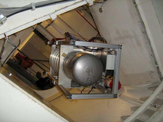
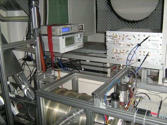

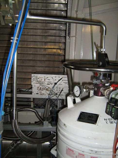
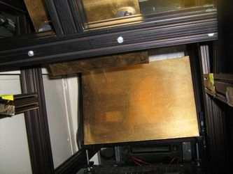
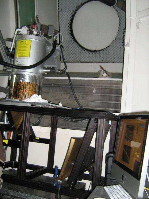
4 NIKA 2 nd run: Installation in the cabin 10/05/2011 SAC meeting IRAM Grenoble 4

")

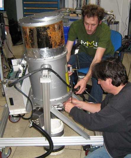
 Skydip Tuning the")
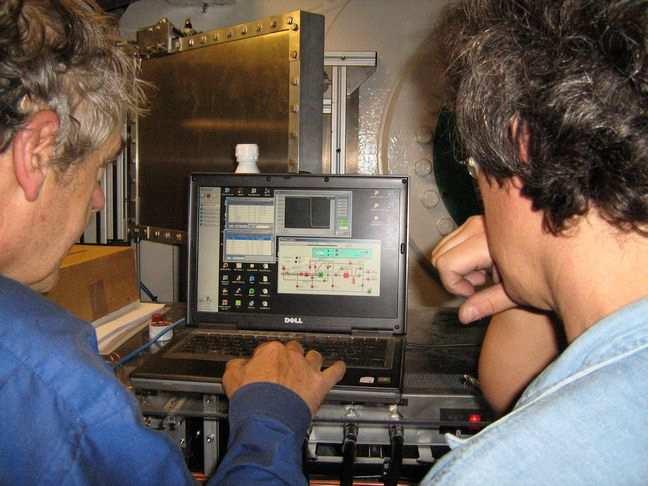
5 NIKA 2 nd run: Preparation phase (acquisition soft, merging with telescope data, detector tuning, ) Control room Mars maps (pointing, focus, calibration...) Skydip Tuning the resonances 10/05/2011 SAC meeting IRAM Grenoble 5

6 NIKA 2 nd run: Example of problems Mysterious 50s period jumps for several random hours B-field jumps Insect in the cabin! Excess noise: EMIR using the chopper 10/05/2011 SAC meeting IRAM Grenoble 6
7 NIKA 2 nd run: Data analysis and results Only using Response in Frequency signal (better than run1) Assumed to be linear with power Calibration From I and Q, get complex phase on calibration circle, then translate to equivalent frequency shift, as measured during KID tuning Traditional transmission amplitude: A 2 = I 2 + Q 2 and phase: ϕ= atan(q/i) 1 A 2 3 KID 1 KID 2 KID 3... Q Resonance loops in I-Q plane A ϕ Equivalent frequency shift: Φ= atan(q-q c /I-I c ) -Φ 0 ~ δf 0 ~ (f 03 /n s )δp i f 0 = resonance frequency, n s = Cooper pair density, P i = incident power ϕ Φ Off-resonance circle 1 3 I 10/05/2011 SAC meeting IRAM Grenoble 7
 IRC 10420 PSS 2322 Integration time [s] 1087 495 2410 2410 2200 1260 1950 Flux measured (1mm, 2mm) [mjy] 17000, 7000 76000, 17700 1700, 1000 94, 21 94 ±12,")
 [mjy s 1/2 ] 2400, 4200 1100, 1100 530, 120 371, 45 330, 29 Cas A (2mm) Crab (2mm) Strong sources: NEFD dominated by source noise (photometric")
8 Source NIKA 2 nd run: Data analysis and results Strong sources (no sky decorrelation) Neptune SgrB2(FIR1) MWC 349 IRC CygA NGC Weak sources (sky decorrelation) IRC PSS 2322 Integration time [s] Flux measured (1mm, 2mm) [mjy] 17000, , , , ±12, 21 ±1 269 ±34, 87 ± ±25, 66 ±3 2 ±12, 1.1 ±0.6 NEFD measured (1mm, 2mm) [mjy s 1/2 ] 2400, , , , , 29 Cas A (2mm) Crab (2mm) Strong sources: NEFD dominated by source noise (photometric reproducibility) Weak sources: conservative NEFDs(mJy s 1/2 ): 1mm, 2mm NET 4 mk s 1/2 10/05/2011 SAC meeting IRAM Grenoble 8
 Multiplexerswitch SQUID")

9 GISMO backend Physical aspect of 2 pixels cold backend on a multiplexed line. Absorber & TES Bias resistor Integrator (Nyquist coil) Multiplexerswitch SQUID and its coils Board 1 Board 2 Board 3 Board 4 I d bias TES I s bias SQUID Equivalent electrical circuit. SQUIDs Amplifier 10/05/2011 SAC meeting IRAM Grenoble 9

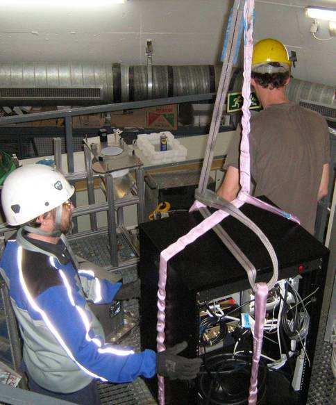
10 GISMO 4 th run: Installation in the cabin 10/05/2011 SAC meeting IRAM Grenoble 10
 Approximation: each ray PSF has the same shape and FWHM along the optical path as long its doesn't encounter a powered surface.")
. => global spill-over on M7 ~ 6%.")
11 GSIMO 4 th run main problem: spill-over on M7 Integrated energy of the diffraction beams at the telescope focal plane (85 mm ; 90 %) (165 mm ; 95 %) (25 mm ; 77 %) Approximation: each ray PSF has the same shape and FWHM along the optical path as long its doesn't encounter a powered surface. => rays have the same encircled energy diagram anywhere in the cabin, they spill over all the mirrors, M7 being the "worse". 50% of the rays are in the 100 mm radius disc centered on the middle of M7 (~5% spill-over for rays at this position). => global spill-over on M7 ~ 6%. 330 mm 70 mm 500 mm 25 mm 85 mm 10/05/2011 SAC meeting IRAM Grenoble 11
12 Call: FOV, number of pixels and mapping speed Number of 0.5 Fλpixels filling a given FOV for each atmospheric window available at the 30m telescope: FOV (diameter) Band center 92 GHz 3.25 mm GHz 2.05 mm GHz 1.2 mm GHz 0.87 mm MAMBO-2: 117 pixels, 11" for each pixel HPBW. Mapping time t ~ NEFD 2 (Ω map /Ωe array ) mapping speed ratio: t MAMBO-2 / t 6.5'FOV,0.5Fλfilled = (35 2 /(117 (11/60) 2 ))/(8.6 2 /6.5 2 ) /05/2011 SAC meeting IRAM Grenoble 12
13 Call: Dynamic and frequency range requirements The background temperature can fluctuate from 20 to 200 K depending on the weather conditions and the elevation. Dynamic range required of an instrument background-limited at any weather condition: T/(NET/2) = 10 6 s -1/2. Typical on-the-fly mapping speed ~10"/s, typical subscan period ~10s. Fluctuations of the atmosphere, and other possible sources (e.g. electronics) create 1/f noise, mostly correlated. Example of spectra obtained with NIKA at the 30m telescope the NEP requirements applies for the Hzfrequency domain Remark: the pixel to pixel stability should last much longer (several minutes) than the stability of the array 10/05/2011 SAC meeting IRAM Grenoble 13
14 Call: Calibration, software, operation, budget Calibration The instrument will have to include elements for the calibrationof the pixels electrical and optical responses. The specifications for laboratory measurements (e.g. sky simulator) are: 5% minimum on the absolute photometry, goal 3% 2% minimum on the relative (inter epoch, inter band) photometry, goal 1%. Software A software allowing to control the instrument, do the interface between the instrument and the telescope control system, and provide calibrated data ina defined format should be delivered together with the instrument. As part of the package, the source code of this acquisition software must be available to IRAM and be documented. Operation Cooling of the instrument shall be obtained with a closed cycled cryogenic system with automatic procedures. Maintenance and science operation should be feasible by trained IRAM staff. The anticipated instrument lifetime is 10 years. Budget The total budget envelop of the instrument is 2 M. The proposing consortium will contribute with a budget of 1 M. This effort will be compensated by guaranteed time for programs using the instrument at the 30m telescope (~1000 /h evenly distributed over 4 years, ~125 hours/ semester). 10/05/2011 SAC meeting IRAM Grenoble 14
, optics and support frame of")

.")
15 Call: Room available in the receiver cabin Space available for the components of the future continuum instrument (red contour), optics and support frame of MAMBO-2 (green),current light path between M3 and M5 (yellow),possible light paths and entries for the future cryostat using anew set of mirrors (light blue arrows and circles). Zemaxsimulations of the telescope FOV limited to 4.5' with current M3, 7' with new M3 (+40% tricking with M2 shift). 10/05/2011 SAC meeting IRAM Grenoble 15


16 Call: Possible optical design for the future instrument Top view Back view Profile view D = 256 D = 270 D = dichroic The cryostat should not exceed m 3, and the field of view cannot exceed /05/2011 SAC meeting IRAM Grenoble 16


17 Call: Possible optical design for the future Back view instrument Profile view Image footprint D = 30mm = 6.5 Strehl (%) Grid distortion max = 1.5 % Encircle energy Top view Spot diagram 10/05/2011 SAC meeting IRAM Grenoble 17


18 Call: Increase 30m FOV Reorganization of the 30m optics refurbishment project: New M3 leg and possibility for motorization New M3 and motorized M4 (Nasmyth~7' FOV, 2012?) move everything in the cabin + new mirrors after M4. S2: "tilted pseudo-nasmyth" S1: "one-armed alt-azimuthal" S3: "horizontal az-alt" current 4' FOV future 7' FOV 10/05/2011 SAC meeting IRAM Grenoble 18
The New IRAM KID Arrays (NIKA) and NIKA-2
 and NIKA-2") The New IRAM KID Arrays (NIKA) and NIKA-2 CONFIRMED for NIKA-2: Institut Néel, IPAG, IRAM, LPSC Grenoble University of Cardiff UK IRAM Granada Spain CEA-Irfu, IAS, IEF Saclay and Orsay France TO BE CONFIRMED:
The New IRAM KID Arrays (NIKA) and NIKA-2 CONFIRMED for NIKA-2: Institut Néel, IPAG, IRAM, LPSC Grenoble University of Cardiff UK IRAM Granada Spain CEA-Irfu, IAS, IEF Saclay and Orsay France TO BE CONFIRMED:
Very Long Baseline Interferometry
 Very Long Baseline Interferometry Cormac Reynolds, JIVE European Radio Interferometry School, Bonn 12 Sept. 2007 VLBI Arrays EVN (Europe, China, South Africa, Arecibo) VLBA (USA) EVN + VLBA coordinate
Detection Beyond 100µm Photon detectors no longer work ("shallow", i.e. low excitation energy, impurities only go out to equivalent of
 Detection Beyond 100µm Photon detectors no longer work ("shallow", i.e. low excitation energy, impurities only go out to equivalent of 100µm) A few tricks let them stretch a little further (like stressing)
Progress Towards Coherent Multibeam Arrays
 Progress Towards Coherent Multibeam Arrays Doug Henke NRC Herzberg Astronomy and Astrophysics, Victoria, Canada August 2016 ALMA Band 3 Receiver (84 116 GHz) Dual linear, 2SB Feed horn OMT (two linear
Etude d un récepteur SIS hétérodyne multi-pixels double polarisation à 3mm de longueur d onde pour le télescope de Pico Veleta
 Etude d un récepteur SIS hétérodyne multi-pixels double polarisation à 3mm de longueur d onde pour le télescope de Pico Veleta Study of a dual polarization SIS heterodyne receiver array for the 3mm band
IYAS 2015 NOEMA. the NOrthern Extended Millimeter Array. K.F. Schuster - IRAM
 NOEMA IYAS 2015 the NOrthern Extended Millimeter Array K.F. Schuster - IRAM IRAM Organization Founded 1978 CNRS (France) MPG (Germany), ING (Spain) joins 1989 HQ Grenoble Admin., Technical Dev. (75 (~70
ALMA Band 9 technology for CCAT. Andrey Baryshev
 ALMA Band 9 technology for CCAT Andrey Baryshev ALMA band 9 group SRON A. Baryshev B. Jackson R. Hesper J. Adema F.P. Mena J. Barkhoff M. Bekema K. Keizer G. Gerlofsma A. Koops J. Panman W. Wild TUDelft
Optics for the 90 GHz GBT array
 Optics for the 90 GHz GBT array Introduction The 90 GHz array will have 64 TES bolometers arranged in an 8 8 square, read out using 8 SQUID multiplexers. It is designed as a facility instrument for the
a simple optical imager
 Imagers and Imaging a simple optical imager Here s one on our 61-Inch Telescope Here s one on our 61-Inch Telescope filter wheel in here dewar preamplifier However, to get a large field we cannot afford
A 1: 128 multiplexing rate Time Domain SQUID Multiplexer
 A 1: 128 multiplexing rate Time Domain SQUID Multiplexer D. Prêle, F. Voisin, M. Piat, T. Decourcelle, C. Perbost, D. Rambaud, S. Maestre, W. Marty, L. Montier Low Temperature Detectors - LTD16 20-24 July
Development of Lumped Element Kinetic Inductance Detectors for NIKA
 > REPLACE THIS LINE WITH YOUR PAPER IDENTIFICATION NUMBER (DOUBLE-CLICK HERE TO EDIT) < 1 Development of Lumped Element Kinetic Inductance Detectors for NIKA M. Roesch, A. Benoit, A. Bideaud, N. Boudou,
Fundamentals of the GBT and Single-Dish Radio Telescopes Dr. Ron Maddalena
 Fundamentals of the GB and Single-Dish Radio elescopes Dr. Ron Maddalena March 2016 Associated Universities, Inc., 2016 National Radio Astronomy Observatory Green Bank, WV National Radio Astronomy Observatory
Telescopes and their configurations. Quick review at the GO level
 Telescopes and their configurations Quick review at the GO level Refraction & Reflection Light travels slower in denser material Speed depends on wavelength Image Formation real Focal Length (f) : Distance
A Millimeter and Submillimeter Kinetic Inductance Detector Camera
 J Low Temp Phys (2008) 151: 684 689 DOI 10.1007/s10909-008-9728-3 A Millimeter and Submillimeter Kinetic Inductance Detector Camera J. Schlaerth A. Vayonakis P. Day J. Glenn J. Gao S. Golwala S. Kumar
Observational Astronomy
 Observational Astronomy Instruments The telescope- instruments combination forms a tightly coupled system: Telescope = collecting photons and forming an image Instruments = registering and analyzing the
Guide to observation planning with GREAT
 Guide to observation planning with GREAT G. Sandell GREAT is a heterodyne receiver designed to observe spectral lines in the THz region with high spectral resolution and sensitivity. Heterodyne receivers
Phased Array Feeds A new technology for multi-beam radio astronomy
 Phased Array Feeds A new technology for multi-beam radio astronomy Aidan Hotan ASKAP Deputy Project Scientist 2 nd October 2015 CSIRO ASTRONOMY AND SPACE SCIENCE Outline Review of radio astronomy concepts.
OPTICS OF SINGLE BEAM, DUAL BEAM & ARRAY RECEIVERS ON LARGE TELESCOPES J A M E S W L A M B, C A L T E C H
 OPTICS OF SINGLE BEAM, DUAL BEAM & ARRAY RECEIVERS ON LARGE TELESCOPES J A M E S W L A M B, C A L T E C H OUTLINE Antenna optics Aberrations Diffraction Single feeds Types of feed Bandwidth Imaging feeds
Pointing Calibration Steps
 ALMA-90.03.00.00-00x-A-SPE 2007 08 02 Specification Document Jeff Mangum & Robert The Man Lucas Page 2 Change Record Revision Date Author Section/ Remarks Page affected 1 2003-10-10 Jeff Mangum All Initial
GHz Single Ended Rx ( Barney ) March 12, 2006 Jacob Kooi, Chip Sumner, Riley Ceria
 March 12, 2006 Jacob Kooi, Chip Sumner, Riley Ceria") 280-420 GHz Single Ended Rx ( Barney ) March 12, 2006 Jacob Kooi, Chip Sumner, Riley Ceria Attached is some information about the new tunerless 345 GHz receiver, nicknamed Barney. Barney has now been installed
280-420 GHz Single Ended Rx ( Barney ) March 12, 2006 Jacob Kooi, Chip Sumner, Riley Ceria Attached is some information about the new tunerless 345 GHz receiver, nicknamed Barney. Barney has now been installed
MMA Memo 143: Report of the Receiver Committee for the MMA
 MMA Memo 143: Report of the Receiver Committee for the MMA 25 September, 1995 John Carlstrom Darrel Emerson Phil Jewell Tony Kerr Steve Padin John Payne Dick Plambeck Marian Pospieszalski Jack Welch, chair
HERA User Manual. The commissioning team version 2.0. November 18, 2009
 HERA User Manual The commissioning team version 2.0 November 18, 2009 1 Introduction The HEterodyne Receiver Array HERA is a receiver system with 18 SIS mixers tunable from 215 to 272 GHz arranged in a
Pupil Planes versus Image Planes Comparison of beam combining concepts
 Pupil Planes versus Image Planes Comparison of beam combining concepts John Young University of Cambridge 27 July 2006 Pupil planes versus Image planes 1 Aims of this presentation Beam combiner functions
The WVR at Effelsberg. Thomas Krichbaum
 The WVR at Effelsberg Alan Roy Ute Teuber Helge Rottmann Thomas Krichbaum Reinhard Keller Dave Graham Walter Alef The Scanning 18-26 GHz WVR for Effelsberg ν = 18.5 GHz to 26.0 GHz Δν = 900 MHz Channels
Introduction to Radio Astronomy. Richard Porcas Max-Planck-Institut fuer Radioastronomie, Bonn
 Introduction to Radio Astronomy Richard Porcas Max-Planck-Institut fuer Radioastronomie, Bonn 1 Contents Radio Waves Radio Emission Processes Radio Noise Radio source names and catalogues Radio telescopes
More Radio Astronomy
 More Radio Astronomy Radio Telescopes - Basic Design A radio telescope is composed of: - a radio reflector (the dish) - an antenna referred to as the feed on to which the radiation is focused - a radio
IF/LO Systems for Single Dish Radio Astronomy Centimeter Wave Receivers
 IF/LO Systems for Single Dish Radio Astronomy Centimeter Wave Receivers Lisa Wray NAIC, Arecibo Observatory Abstract. Radio astronomy receivers designed to detect electromagnetic waves from faint celestial
PdBI data calibration. Vincent Pie tu IRAM Grenoble
 PdBI data calibration Vincent Pie tu IRAM Grenoble IRAM mm-interferometry School 2008 1 Data processing strategy 2 Data processing strategy Begins with proposal/setup preparation. Depends on the scientific
FUTURE INSTRUMENTATION FOR JCMT II
 FUTURE INSTRUMENTATION FOR JCMT II Dan Bintley and Per Friberg East Asian Observatory East Asia Sub-millimeter-wave Receiver Technology Workshop 1 ABSTRACT The EAO's James Clerk Maxwell Telescope (JCMT)
SONG Stellar Observations Network Group. The prototype
 SONG Stellar Observations Network Group The prototype F. Grundahl1, J. Christensen Dalsgaard1, U. G. Jørgensen2, H. Kjeldsen1,S. Frandsen1 and P. Kjærgaard2 1) Danish AsteroSeismology Centre, University
SOAR Integral Field Spectrograph (SIFS): Call for Science Verification Proposals
: Call for Science Verification Proposals") Published on SOAR (http://www.ctio.noao.edu/soar) Home > SOAR Integral Field Spectrograph (SIFS): Call for Science Verification Proposals SOAR Integral Field Spectrograph (SIFS): Call for Science Verification
Published on SOAR (http://www.ctio.noao.edu/soar) Home > SOAR Integral Field Spectrograph (SIFS): Call for Science Verification Proposals SOAR Integral Field Spectrograph (SIFS): Call for Science Verification
Antennas. Greg Taylor. University of New Mexico Spring Astronomy 423 at UNM Radio Astronomy
 Antennas Greg Taylor University of New Mexico Spring 2011 Astronomy 423 at UNM Radio Astronomy Radio Window 2 spans a wide range of λ and ν from λ ~ 0.33 mm to ~ 20 m! (ν = 1300 GHz to 15 MHz ) Outline
Sideband Smear: Sideband Separation with the ALMA 2SB and DSB Total Power Receivers
 and DSB Total Power Receivers SCI-00.00.00.00-001-A-PLA Version: A 2007-06-11 Prepared By: Organization Date Anthony J. Remijan NRAO A. Wootten T. Hunter J.M. Payne D.T. Emerson P.R. Jewell R.N. Martin
Receiver Performance and Comparison of Incoherent (bolometer) and Coherent (receiver) detection
 and Coherent (receiver) detection") At ev gap /h the photons have sufficient energy to break the Cooper pairs and the SIS performance degrades. Receiver Performance and Comparison of Incoherent (bolometer) and Coherent (receiver) detection
At ev gap /h the photons have sufficient energy to break the Cooper pairs and the SIS performance degrades. Receiver Performance and Comparison of Incoherent (bolometer) and Coherent (receiver) detection
G. Serra.
 G. Serra gserra@oa-cagliari.inaf.it on behalf of Metrology team* *T. Pisanu, S. Poppi, F.Buffa, P. Marongiu, R. Concu, G. Vargiu, P. Bolli, A. Saba, M.Pili, E.Urru Astronomical Observatory of Cagliari
Solar Optical Telescope (SOT)
") Solar Optical Telescope (SOT) The Solar-B Solar Optical Telescope (SOT) will be the largest telescope with highest performance ever to observe the sun from space. The telescope itself (the so-called Optical
Solar Optical Telescope (SOT) The Solar-B Solar Optical Telescope (SOT) will be the largest telescope with highest performance ever to observe the sun from space. The telescope itself (the so-called Optical
NASTER System Definition Proposal
 Remote Sensing Team NASTER System Definition Proposal All rights reserved. - 7/14/03 Page 1 Overview Review and comment the mid-ir requirements Presentation of ABB s current platform technology Proposed
Acknowledgements CEA-Saclay / SAp Boulade Olivier, Doumayrou Eric, Horeau Benoit, Lepennec Yannick, Martignac Jerome, Okumura Koryo, Révéret Vincent,
 Recent Achievements in the Development of HERSCHEL/PACS Bolometer Arrays Nicolas BILLOT nbillot@cea.fr CEA - Saclay/DAPNIA/SAp UMR - Astrophysique Interaction Multi-echelle Acknowledgements CEA-Saclay
APEX training 2014 HETERODYNE GROUP FLASH & CHAMP. MPIfR Division for Submm Technologies Heterodyne Group
 HETERODYNE GROUP APEX training 2014 FLASH & CHAMP MPIfR Division for Submm Technologies Heterodyne Group March 2014 FLASH+ instrument - receiver capabilities bias control PC simultaneous observations at
12.4 Alignment and Manufacturing Tolerances for Segmented Telescopes
 330 Chapter 12 12.4 Alignment and Manufacturing Tolerances for Segmented Telescopes Similar to the JWST, the next-generation large-aperture space telescope for optical and UV astronomy has a segmented
Antennas. Greg Taylor. University of New Mexico Spring Astronomy 423 at UNM Radio Astronomy
 Antennas Greg Taylor University of New Mexico Spring 2017 Astronomy 423 at UNM Radio Astronomy Outline 2 Fourier Transforms Interferometer block diagram Antenna fundamentals Types of antennas Antenna performance
Aberration Theory and Prototype Mirror Experiments
 Aberration Theory and Prototype Mirror Experiments Bruce Holenstein, Rich Mitchell, Dylan Holenstein 2010-2011 Alt-Az Initiative Hawaii Conference on Light Bucket Astronomy 1 Some Light Bucket Aberration
Anne-Laure Fontana, Catherine Boucher, Yves Bortolotti, Florence Cope, Bastien Lefranc, Alessandro Navarrini, Doris Maier, Karl-F.
 Multi-beam SIS Receiver Development Anne-Laure Fontana, Catherine Boucher, Yves Bortolotti, Florence Cope, Bastien Lefranc, Alessandro Navarrini, Doris Maier, Karl-F. Schuster & Irvin Still Institut t
Multiplying Interferometers
 Multiplying Interferometers L1 * L2 T + iv R1 * R2 T - iv L1 * R2 Q + iu R1 * L2 Q - iu Since each antenna can output both L and R polarization, all 4 Stokes parameters are simultaneously measured without
Radio Astronomy: SKA-Era Interferometry and Other Challenges. Dr Jasper Horrell, SKA SA (and Dr Oleg Smirnov, Rhodes and SKA SA)
") Radio Astronomy: SKA-Era Interferometry and Other Challenges Dr Jasper Horrell, SKA SA (and Dr Oleg Smirnov, Rhodes and SKA SA) ASSA Symposium, Cape Town, Oct 2012 Scope SKA antenna types Single dishes
Radio Astronomy: SKA-Era Interferometry and Other Challenges Dr Jasper Horrell, SKA SA (and Dr Oleg Smirnov, Rhodes and SKA SA) ASSA Symposium, Cape Town, Oct 2012 Scope SKA antenna types Single dishes
Submillimeter (continued)
") Submillimeter (continued) Dual Polarization, Sideband Separating Receiver Dual Mixer Unit The 12-m Receiver Here is where the receiver lives, at the telescope focus Receiver Performance T N (noise temperature)
Submillimeter (continued) Dual Polarization, Sideband Separating Receiver Dual Mixer Unit The 12-m Receiver Here is where the receiver lives, at the telescope focus Receiver Performance T N (noise temperature)
The Q/U Imaging ExperimenT (QUIET) receivers Coherent Polarimeter Arrays at 40 and 90 GHz
 receivers Coherent Polarimeter Arrays at 40 and 90 GHz") The Q/U Imaging ExperimenT (QUIET) receivers Coherent Polarimeter Arrays at 40 and 90 GHz Dorothea Samtleben, Max-Planck-Institut für Radioastronomie, Bonn Universe becomes transparent => Release of Cosmic
The Q/U Imaging ExperimenT (QUIET) receivers Coherent Polarimeter Arrays at 40 and 90 GHz Dorothea Samtleben, Max-Planck-Institut für Radioastronomie, Bonn Universe becomes transparent => Release of Cosmic
Dynamic beam shaping with programmable diffractive optics
 Dynamic beam shaping with programmable diffractive optics Bosanta R. Boruah Dept. of Physics, GU Page 1 Outline of the talk Introduction Holography Programmable diffractive optics Laser scanning confocal
MAORY E-ELT MCAO module project overview
 MAORY E-ELT MCAO module project overview Emiliano Diolaiti Istituto Nazionale di Astrofisica Osservatorio Astronomico di Bologna On behalf of the MAORY Consortium AO4ELT3, Firenze, 27-31 May 2013 MAORY
Large-field imaging. Frédéric Gueth, IRAM Grenoble. 7th IRAM Millimeter Interferometry School 4 8 October 2010
 Large-field imaging Frédéric Gueth, IRAM Grenoble 7th IRAM Millimeter Interferometry School 4 8 October 2010 Large-field imaging The problems The field of view is limited by the antenna primary beam width
Simultaneous Infrared-Visible Imager/Spectrograph a Multi-Purpose Instrument for the Magdalena Ridge Observatory 2.4-m Telescope
 Simultaneous Infrared-Visible Imager/Spectrograph a Multi-Purpose Instrument for the Magdalena Ridge Observatory 2.4-m Telescope M.B. Vincent *, E.V. Ryan Magdalena Ridge Observatory, New Mexico Institute
ALMA Memo 553. First Astronomical Observations with an ALMA Band 6 ( GHz) Sideband-Separating SIS Mixer-Preamp
 Sideband-Separating SIS Mixer-Preamp") Presented at the 17 th International Symposium on Space Terahertz Technology, Paris, May 2006. http://www.alma.nrao.edu/memos/ ALMA Memo 553 15 August 2006 First Astronomical Observations with an ALMA
Presented at the 17 th International Symposium on Space Terahertz Technology, Paris, May 2006. http://www.alma.nrao.edu/memos/ ALMA Memo 553 15 August 2006 First Astronomical Observations with an ALMA
The Phased Array Feed Receiver System : Linearity, Cross coupling and Image Rejection
 The Phased Array Feed Receiver System : Linearity, Cross coupling and Image Rejection D. Anish Roshi 1,2, Robert Simon 1, Steve White 1, William Shillue 2, Richard J. Fisher 2 1 National Radio Astronomy
Light gathering Power: Magnification with eyepiece:
 Telescopes Light gathering Power: The amount of light that can be gathered by a telescope in a given amount of time: t 1 /t 2 = (D 2 /D 1 ) 2 The larger the diameter the smaller the amount of time. If
Antennas & Receivers in Radio Astronomy
 Antennas & Receivers in Radio Astronomy Mark McKinnon Fifteenth Synthesis Imaging Workshop 1-8 June 2016 Purpose & Outline Purpose: describe how antenna elements can affect the quality of images produced
Wavefront sensor design for NGAO: Assumptions, Design Parameters and Technical Challenges Version 0.1
 Wavefront sensor design for NGAO: Assumptions, Design Parameters and Technical Challenges Version 0.1 V. Velur Caltech Optical Observatories M/S 105-24, 1200 E California Blvd., Pasadena, CA 91125 Sept.
Puntino. Shack-Hartmann wavefront sensor for optimizing telescopes. The software people for optics
 Puntino Shack-Hartmann wavefront sensor for optimizing telescopes 1 1. Optimize telescope performance with a powerful set of tools A finely tuned telescope is the key to obtaining deep, high-quality astronomical
Holography Transmitter Design Bill Shillue 2000-Oct-03
 Holography Transmitter Design Bill Shillue 2000-Oct-03 Planned Photonic Reference Distribution for Test Interferometer The transmitter for the holography receiver is made up mostly of parts that are already
TECHNOLOGICAL DEVELOPMENTS AT IGN INSTRUMENTATION AND TECHNOLOGICAL DEVELOPMENTS AT THE IGN
 INSTRUMENTATION AND TECHNOLOGICAL DEVELOPMENTS AT THE IGN Yebes Observatory is a Fundamental Geodetic Station where Astronomical, Geodetic and Geophysical techniques are combined. Yebes, Guadalajara, Spain
EVLA System Commissioning Results
 EVLA System Commissioning Results EVLA Advisory Committee Meeting, March 19-20, 2009 Rick Perley EVLA Project Scientist t 1 Project Requirements EVLA Project Book, Chapter 2, contains the EVLA Project
1.6 Beam Wander vs. Image Jitter
 8 Chapter 1 1.6 Beam Wander vs. Image Jitter It is common at this point to look at beam wander and image jitter and ask what differentiates them. Consider a cooperative optical communication system that
The MCAO module for the E-ELT.
 The MCAO module for the E-ELT http://www.bo.astro.it/~maory Paolo Ciliegi (INAF Osservatorio Astronomico di Bologna) On behalf of the MAORY Consortium MAORY Consortium INAF BOLOGNA UNIVERSITY ONERA ESO
visibility values: 1) V1=0.5 2) V2=0.9 3) V3=0.99 b) In the three cases considered, what are the values of FSR (Free Spectral Range) and
 V1=0.5 2) V2=0.9 3) V3=0.99 b) In the three cases considered, what are the values of FSR (Free Spectral Range) and") EXERCISES OF OPTICAL MEASUREMENTS BY ENRICO RANDONE AND CESARE SVELTO EXERCISE 1 A CW laser radiation (λ=2.1 µm) is delivered to a Fabry-Pérot interferometer made of 2 identical plane and parallel mirrors
EXERCISES OF OPTICAL MEASUREMENTS BY ENRICO RANDONE AND CESARE SVELTO EXERCISE 1 A CW laser radiation (λ=2.1 µm) is delivered to a Fabry-Pérot interferometer made of 2 identical plane and parallel mirrors
To print higher-resolution math symbols, click the Hi-Res Fonts for Printing button on the jsmath control panel.
 To print higher-resolution math symbols, click the Hi-Res Fonts for Printing button on the jsmath control panel. Radiometers Natural radio emission from the cosmic microwave background, discrete astronomical
Active Impedance Matched Dual-Polarization Phased Array Feed for the GBT
 Active Impedance Matched Dual-Polarization Phased Array Feed for the GBT Karl F. Warnick, David Carter, Taylor Webb, Brian D. Jeffs Department of Electrical and Computer Engineering Brigham Young University,
Phased Array Feeds & Primary Beams
 Phased Array Feeds & Primary Beams Aidan Hotan ASKAP Deputy Project Scientist 3 rd October 2014 CSIRO ASTRONOMY AND SPACE SCIENCE Outline Review of parabolic (dish) antennas. Focal plane response to a
Reference and User Manual May, 2015 revision - 3
 Reference and User Manual May, 2015 revision - 3 Innovations Foresight 2015 - Powered by Alcor System 1 For any improvement and suggestions, please contact customerservice@innovationsforesight.com Some
Characterization of Various Quasi-Optical Components for the Submillimeter Limb-Sounder SMILES
 Characterization of Various Quasi-Optical Components for the Submillimeter Limb-Sounder SMILES A. Murk, N. Kämpfer, R. Wylde, J. Inatani, T. Manabe and M. Seta E-mail: axel.murk@mw.iap.unibe.ch University
MIRI The Mid-Infrared Instrument for the JWST. ESO, Garching 13 th April 2010 Alistair Glasse (MIRI Instrument Scientist)
") MIRI The Mid-Infrared Instrument for the JWST ESO, Garching 13 th April 2010 Alistair Glasse (MIRI Instrument Scientist) 1 Summary MIRI overview, status and vital statistics. Sensitivity, saturation and
MIRI The Mid-Infrared Instrument for the JWST ESO, Garching 13 th April 2010 Alistair Glasse (MIRI Instrument Scientist) 1 Summary MIRI overview, status and vital statistics. Sensitivity, saturation and
Receiver Design for Passive Millimeter Wave (PMMW) Imaging
 Imaging") Introduction Receiver Design for Passive Millimeter Wave (PMMW) Imaging Millimeter Wave Systems, LLC Passive Millimeter Wave (PMMW) sensors are used for remote sensing and security applications. They rely
Introduction Receiver Design for Passive Millimeter Wave (PMMW) Imaging Millimeter Wave Systems, LLC Passive Millimeter Wave (PMMW) sensors are used for remote sensing and security applications. They rely
ALMA water vapour radiometer project
 ALMA water vapour radiometer project Why water vapour radiometers? Science requirements/instrument specifications Previous work ALMA Phase 1 work Kate Isaak and Richard Hills Cavendish Astrophysics, Cambridge
Final Feed Selection Study For the Multi Beam Array System
 National Astronomy and Ionosphere Center Arecibo Observatory Focal Array Memo Series Final Feed Selection Study For the Multi Beam Array System By: Germán Cortés-Medellín CORNELL July/19/2002 U n i v e
MAORY ADAPTIVE OPTICS
 MAORY ADAPTIVE OPTICS Laura Schreiber, Carmelo Arcidiacono, Giovanni Bregoli, Fausto Cortecchia, Giuseppe Cosentino (DiFA), Emiliano Diolaiti, Italo Foppiani, Matteo Lombini, Mauro Patti (DiFA-OABO) MAORY
Influence of Temperature Variations on the Stability of a Submm Wave Receiver
 Influence of Temperature Variations on the Stability of a Submm Wave A. Baryshev 1, R. Hesper 1, G. Gerlofsma 1, M. Kroug 2, W. Wild 3 1 NOVA/SRON/RuG 2 DIMES/TuD 3 SRON / RuG Abstract Radio astronomy
First tests of prototype SCUBA-2 array
 First tests of prototype SCUBA-2 array Adam Woodcraft Astronomical Instrumentation Group School of Physics and Astronomy,Cardiff University http://woodcraft.lowtemp lowtemp.org/ Techniques and Instrumentation
Performance of the Prototype NLC RF Phase and Timing Distribution System *
 SLAC PUB 8458 June 2000 Performance of the Prototype NLC RF Phase and Timing Distribution System * Josef Frisch, David G. Brown, Eugene Cisneros Stanford Linear Accelerator Center, Stanford University,
Phased Array Feeds A new technology for wide-field radio astronomy
 Phased Array Feeds A new technology for wide-field radio astronomy Aidan Hotan ASKAP Project Scientist 29 th September 2017 CSIRO ASTRONOMY AND SPACE SCIENCE Outline Review of radio astronomy concepts
A Crash Course in Radio Astronomy and Interferometry: 1. Basic Radio/mm Astronomy
 A Crash Course in Radio Astronomy and Interferometry: 1. Basic Radio/mm Astronomy James Di Francesco National Research Council of Canada North American ALMA Regional Center Victoria (thanks to S. Dougherty,
Dynamic Range. Can I look at bright and faint things at the same time?
 Detector Basics The purpose of any detector is to record the light collected by the telescope. All detectors transform the incident radiation into a some other form to create a permanent record, such as
Sensor Fusion Enables Comprehensive Analysis of Laser Processing in Additive Manufacturing
 MKS Instruments 1 of 6 Sensor Fusion Enables Comprehensive Analysis of Laser Processing in Additive Manufacturing By Kevin Kirkham, Senior Manager, Product Development, Ophir Sensor: "A device that detects
Added Phase Noise measurement for EMBRACE LO distribution system
 Added Phase Noise measurement for EMBRACE LO distribution system G. Bianchi 1, S. Mariotti 1, J. Morawietz 2 1 INAF-IRA (I), 2 ASTRON (NL) 1. Introduction Embrace is a system composed by 150 receivers,
AGRON / E E / MTEOR 518 Laboratory
 AGRON / E E / MTEOR 518 Laboratory Brian Hornbuckle, Nolan Jessen, and John Basart April 5, 2018 1 Objectives In this laboratory you will: 1. identify the main components of a ground based microwave radiometer
Mini Workshop Interferometry. ESO Vitacura, 28 January Presentation by Sébastien Morel (MIDI Instrument Scientist, Paranal Observatory)
") Mini Workshop Interferometry ESO Vitacura, 28 January 2004 - Presentation by Sébastien Morel (MIDI Instrument Scientist, Paranal Observatory) MIDI (MID-infrared Interferometric instrument) 1st generation
Mini Workshop Interferometry ESO Vitacura, 28 January 2004 - Presentation by Sébastien Morel (MIDI Instrument Scientist, Paranal Observatory) MIDI (MID-infrared Interferometric instrument) 1st generation
EVLA Scientific Commissioning and Antenna Performance Test Check List
 EVLA Scientific Commissioning and Antenna Performance Test Check List C. J. Chandler, C. L. Carilli, R. Perley, October 17, 2005 The following requirements come from Chapter 2 of the EVLA Project Book.
Twelve voice signals, each band-limited to 3 khz, are frequency -multiplexed using 1 khz guard bands between channels and between the main carrier
 Twelve voice signals, each band-limited to 3 khz, are frequency -multiplexed using 1 khz guard bands between channels and between the main carrier and the first channel. The modulation of the main carrier
Going towards the read-out of a 160 pixel FDM system for SAFARI 76 pixels connected
 Going towards the read-out of a 160 pixel FDM system for SAFARI 76 pixels connected R.A. Hijmering R. den Hartog J. van der Kuur J.R. Gao M. Ridder A.J. v/d Linden SPICA/SAFARI SPICA (JAXA/ESA) Infrared
Memo 65 SKA Signal processing costs
 Memo 65 SKA Signal processing costs John Bunton, CSIRO ICT Centre 12/08/05 www.skatelescope.org/pages/page_memos.htm Introduction The delay in the building of the SKA has a significant impact on the signal
HIFI. FPU Failure Mode Effects and Criticallity Analysis. FPSS.ID.: FPSS Inst.ID.: SRON-G/FPU/TN/ Issue: 1 Date: 06OCT2000 Category: 3
 FPSS.ID.: FPSS-0010 Inst.ID.: SRON-G/FPU/TN/2000-003 Date: 06OCT2000 FPU Failure Mode Effects and Criticallity Analysis Prepared by: K.J. Wildeman date: October 6, 2000 Total Pages: 1 (incl. cover) Inst.no.:
Superconducting Transition-Edge Sensors and Superconducting Tunnel Junctions for Optical/UV Time-Energy Resolved Single-Photon Counters
 Superconducting Transition-Edge Sensors and Superconducting Tunnel Junctions for Optical/UV Time-Energy Resolved Single-Photon Counters NHST Meeting STScI - Baltimore 10 April 2003 TES & STJ Detector Summary
esma SOFTWARE INTERFACE Mark Bentum Version 0.3 August 10, 2005
 esma SOFTWARE INTERFACE Mark Bentum Version 0.3 August 10, 2005 In this document the software issues of the esma will be discussed. The esma, the extended Submillimeter Array, is a visiting instrument
Laser Beam Analysis Using Image Processing
 Journal of Computer Science 2 (): 09-3, 2006 ISSN 549-3636 Science Publications, 2006 Laser Beam Analysis Using Image Processing Yas A. Alsultanny Computer Science Department, Amman Arab University for
EVLA Memo 105. Phase coherence of the EVLA radio telescope
 EVLA Memo 105 Phase coherence of the EVLA radio telescope Steven Durand, James Jackson, and Keith Morris National Radio Astronomy Observatory, 1003 Lopezville Road, Socorro, NM, USA 87801 ABSTRACT The
ARRAY CONFIGURATION AND TOTAL POWER CALIBRATION FOR LEDA
 ARRAY CONFIGURATION AND TOTAL POWER CALIBRATION FOR LEDA Frank Schinzel & Joe Craig (UNM) on behalf of the LEDA Collaboration USNC-URSI National Radio Science Meeting 2013 - Boulder, 09.01.2013 What is
Radiometric Solar Telescope (RaST) The case for a Radiometric Solar Imager,
 The case for a Radiometric Solar Imager,") SORCE Science Meeting 29 January 2014 Mark Rast Laboratory for Atmospheric and Space Physics University of Colorado, Boulder Radiometric Solar Telescope (RaST) The case for a Radiometric Solar Imager,
SORCE Science Meeting 29 January 2014 Mark Rast Laboratory for Atmospheric and Space Physics University of Colorado, Boulder Radiometric Solar Telescope (RaST) The case for a Radiometric Solar Imager,
Chapter 3. Instrumentation. 3.1 Telescope Site Layout. 3.2 Telescope Optics
 Chapter 3 Instrumentation 3.1 Telescope Site Layout The 12m is located on the southwest ridge of Kitt Peak, about two miles below the top of the mountain. Other telescopes on the southwest ridge are the
TIRCAM2 (TIFR Near Infrared Imaging Camera - 3.6m Devasthal Optical Telescope (DOT)
") TIRCAM2 (TIFR Near Infrared Imaging Camera - II) @ 3.6m Devasthal Optical Telescope (DOT) (ver 4.0 June 2017) TIRCAM2 (TIFR Near Infrared Imaging Camera - II) is a closed cycle cooled imager that has been
TIRCAM2 (TIFR Near Infrared Imaging Camera - II) @ 3.6m Devasthal Optical Telescope (DOT) (ver 4.0 June 2017) TIRCAM2 (TIFR Near Infrared Imaging Camera - II) is a closed cycle cooled imager that has been
Random Phase Antenna Combining for SETI SETICon03
 Random Phase Antenna Combining for SETI SETICon03 Marko Cebokli S57UUU ABSTRACT: Since the direction from which the first ETI signal will arrive is not known in advance, it is possible to relax the phasing
Radio Interferometry. Xuening Bai. AST 542 Observational Seminar May 4, 2011
 Radio Interferometry Xuening Bai AST 542 Observational Seminar May 4, 2011 Outline Single-dish radio telescope Two-element interferometer Interferometer arrays and aperture synthesis Very-long base line
CAPMAP Control of Systematic Effects
 CAPMAP Control of Systematic Effects Jeff McMahon Kavli Institute for Cosmological Physics University of Chicago Inflation Probe Systematics Workshop Annapolis, MD, July 28-30, 2008 The CAPMAP Collaboration
Instruction manual for T3DS software. Tool for THz Time-Domain Spectroscopy. Release 4.0
 Instruction manual for T3DS software Release 4.0 Table of contents 0. Setup... 3 1. Start-up... 5 2. Input parameters and delay line control... 6 3. Slow scan measurement... 8 4. Fast scan measurement...