a simple optical imager
|
|
|
- Ralph Porter
- 6 years ago
- Views:
Transcription
1 Imagers and Imaging
2 a simple optical imager
3 Here s one on our 61-Inch Telescope

4 Here s one on our 61-Inch Telescope filter wheel in here dewar preamplifier

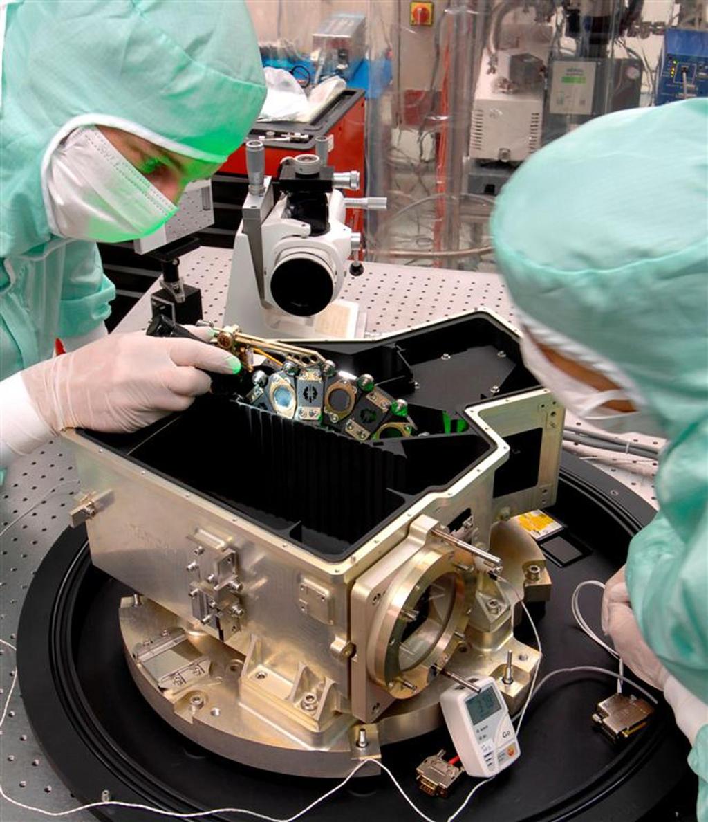
5 However, to get a large field we cannot afford to just buy more CCDs and continue to mount them at the Cassegrain focus - we have provide a faster beam to shrink the projected pixel scale. Here is the 90- Prime camera as an example.
6 Most of the instrument volume is a series of lenses to map the field onto a mosaic of four 4K X 4K CCDs with 15mm pixels at a pixel scale of 0.45 /pixel. The final f/ratio is 2.98 and the field of view is 1.16 X 1.16 degrees (when all the CCDs are working).?? The primary f/ratio is why does it have to be re-imaged?
7 Here is a cutaway drawing of a dewar similar to the one on 90-Prime. The radiation shield is important to reduce thermal loads.
8 The requirement for cold baffling makes an infrared camera more complex. This is the Gemini near infrared camera. The detector is a 1024 X 1024 InSb array with 25mm pixels with projected scales from (shown) to /pixel.

9 The optics are folded to fit within a compact dewar.

10 MIRI (and VISIR on the VLT) has an all-reflective optical design that gives good images over a reasonably large field. folds forms pupil three mirror anastigmat

11 The optics are folded to be extremely compact.
12
.")
13 NIRCam overall layout; there are two identical cameras, to give maximum reliability (no single failure within the camera can cause loss of the NIRCam capabilities). An optical wedge brings the coronagraphs into the field without sacrificing FOV.

14 Each camera has a short and long wavelength arm for efficiency. The first optics stage is shared between the arms and the optics are folded for compactness.
15 MegaCam - a Cassegrain imager on the MMT

16 The MegaCam focal plane. The pixels project to 0.1 on the sky.

17 Now here s a BIG camera!
18 The optics look pretty familiar, though.
19
20
21 The images are very uniform in terms of encircled energy, but the images themselves change substantially.
22 Here is the focal plane. The extra small CCDs are used for guiding and out of focus image analysis.

23 Some CCD Specs: QE > 85% CTE > Read Noise < 5e Surface < 7mm peakto-valley f/ratio: % of energy in one pixel Pixel scale 0.23 FOV ~ 23 arcmin
24

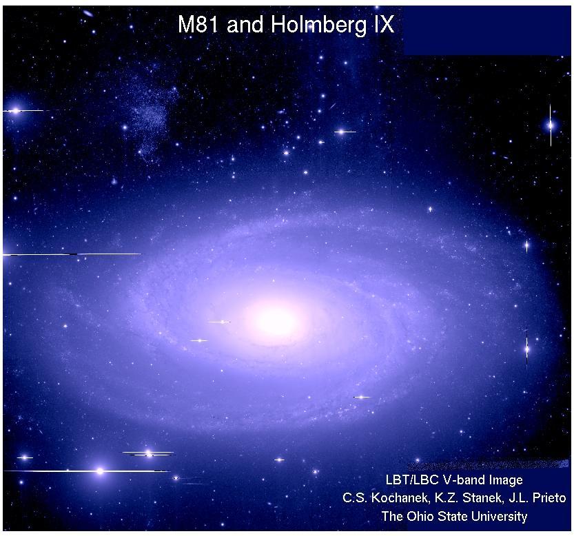
25 Holmberg IX
26 OK, it s a lovely image, but how do we get the most out of it? Here is a menagerie of problems:
27 Pixel scale = 0.23 /pixel: how was it set??? Here is the MTF for the array (should be familiar ). Pixels need to be about half the FWHM of the image, or information is lost. Some can be recovered by dithering on a subpixel scale.
28 Because they put the filters near the focal plane, standard optical designs make stringent demands on filter uniformity; even if filters are uniform, dirt on them (or bugs) and reflections can be problems. Such issues are best dealt with by a lot of dithering while taking images.
29 Infrared cameras often provide a better solution by putting the filters at a pupil. filters can be at a pupil
 and taken")
30 Imagers typically have distortion here is the result for the MIRI imager. This is typically fitted with polynomials (often based on the optical design) and taken out in software.


31 More Problems: Ghost images cos N
32 Response gaps between pixels Response variations across a pixel


33 Latent images, fringing, bleeding, cross talk from one pixel to another in general.

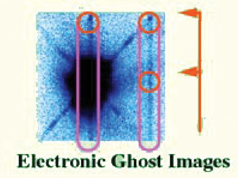
34 Electronic ghosts, amplifier glow, pedestal effect

 See Orion arrays to right Thermal drifts Freeze-out of")
35 Hot and dead pixels Fixed patterns due to readout and array growth processes - see Orion arrays to right - 2K X 2K InSb Cosmic ray hits Amplifier transients Nonlinearity and soft saturation Photon emitting defects (PEDs) See Orion arrays to right Thermal drifts Freeze-out of charge carriers
36 Don t Despair!! Repetition is important Lets you remove transient signals like cosmic ray hits, amplifier transients Not changing things is important Many array artifacts like pedestal effects and MUX glow can be removed almost perfectly if the observing conditions are not changed Thermal drifts are minimized by keeping a constant cadence on the array Dithering is also important - putting the signal on a variety of pixels Lets you replace bad pixels with good data Allows generating calibration frames from the sky - can be the best kind of calibration Can allow you to identify and remove latent images
37 Reference pixels (IR arrays) or overscan (CCDs) may help solve some problems Let you track the behavior of the readout electronics and fix it in data reduction However, are not a cure-all, and in many cases behave sufficiently differently from the live pixels that they are not helpful Pixel scale is important Coarse pixel scales (relative to Nyquist) lose information irretrievably Coarse pixels make it difficult to remove intra-pixel sensitivity variations, make your measurements susceptible to inter-pixel gaps and cross talk, make cross talk a more significant problem, and so forth. Fine pixels limit the field of view and may increase the effective noise Information loss with undersampled data Intrapixel sensitivity variations can make your results ambiguous; standard reductions will miss pixel sensitivity variations (left) and may not give correct results imaging in spectral lines with fringing in the detector (right)
38 Assuming you have done everything right, you need to calibrate your raw data: Calibration must take into account the differing properties of the detectors in the array: pixel-to-pixel variations in amplifier offset pixel-to-pixel variations in dark current pixel-to-pixel variations in responsivity Three unknowns require three sets of data: Offset frame (sometimes called bias frame): very short exposure, no signals Dark current frame: long exposure, no signals Response frame (sometimes called flat field): uniform illumination Image data reduction consists of: Subtract offset from data, dark, and response frames to obtain data, dark, and response. Scale dark to exposure time of data and response and subtract from them to get data and response Divide data by response The result: if the data frame has a uniform exposure, then the product will be a uniform image at a level corresponding to the ratio of the exposure on the data frame to the exposure on the response frame (exposure = level of illumination multiplied by the exposure time). Sources will appear on top of this uniform background.
39 For best results Dark current and response frames may need to be obtained close in time to the data frames It may be necessary to use identical integration times for dark, response, and data frames Response and data frames should be taken with illumination of identical spectral character Need a minimum of 3 frames on source 5 or more is better to be sure there are no transient bad pixels (e.g., cosmic ray hits) Permanent bad pixels can be masked out by replacing values with the average of those from surrounding pixels. However, doing so can give bad data that looks good. It is better to take multiple exposures and move the source on the array between them to fill in the source structure with all good data bad pixels then just reduce the integration time at some points in the image.
40 A good strategy for imaging is: Take repeated exposures of the field, moving the source on the array between exposures Generate the response frame by a median average of these frames sources will disappear because they do not appear at the same place on any two frames Obtain dark frames with the same exposure time as used for the data and response frames Subtract dark from data and response (also takes out offset); divide corrected data by corrected response Shift frames to correct for frame-to-frame image motions Median average again to eliminate bad pixels and cosmic rays, while gaining signal to noise on the source image A more detailed description has been posted on the course syllabus! Once you have gotten to this point, you can use the image to measure positions (astrometry - next lecture) or photometry (coming soon).
Properties of a Detector
 Properties of a Detector Quantum Efficiency fraction of photons detected wavelength and spatially dependent Dynamic Range difference between lowest and highest measurable flux Linearity detection rate
CCD reductions techniques
 CCD reductions techniques Origin of noise Noise: whatever phenomena that increase the uncertainty or error of a signal Origin of noises: 1. Poisson fluctuation in counting photons (shot noise) 2. Pixel-pixel
Observing*Checklist:*A3ernoon*
 Ay#122a:# Intro#to#Observing/Image#Processing# (Many&slides&today& c/o&m.&bolte)& Observing*Checklist:*A3ernoon* Set*up*instrument*(verify*and*set*filters,*gra@ngs,*etc.)* Set*up*detector*(format,*gain,*binning)*
Observation Data. Optical Images
 Data Analysis Introduction Optical Imaging Tsuyoshi Terai Subaru Telescope Imaging Observation Measure the light from celestial objects and understand their physics Take images of objects with a specific
INTRODUCTION TO CCD IMAGING
 ASTR 1030 Astronomy Lab 85 Intro to CCD Imaging INTRODUCTION TO CCD IMAGING SYNOPSIS: In this lab we will learn about some of the advantages of CCD cameras for use in astronomy and how to process an image.
Abstract. Preface. Acknowledgments
 Contents Abstract Preface Acknowledgments iv v vii 1 Introduction 1 1.1 A Very Brief History of Visible Detectors in Astronomy................ 1 1.2 The CCD: Astronomy s Champion Workhorse......................
The 0.84 m Telescope OAN/SPM - BC, Mexico
 The 0.84 m Telescope OAN/SPM - BC, Mexico Readout error CCD zero-level (bias) ramping CCD bias frame banding Shutter failure Significant dark current Image malting Focus frame taken during twilight IR
What an Observational Astronomer needs to know!
 What an Observational Astronomer needs to know! IRAF:Photometry D. Hatzidimitriou Masters course on Methods of Observations and Analysis in Astronomy Basic concepts Counts how are they related to the actual
Charged Coupled Device (CCD) S.Vidhya
 S.Vidhya") Charged Coupled Device (CCD) S.Vidhya 02.04.2016 Sensor Physical phenomenon Sensor Measurement Output A sensor is a device that measures a physical quantity and converts it into a signal which can be read
Charged Coupled Device (CCD) S.Vidhya 02.04.2016 Sensor Physical phenomenon Sensor Measurement Output A sensor is a device that measures a physical quantity and converts it into a signal which can be read
Charged-Coupled Devices
 Charged-Coupled Devices Charged-Coupled Devices Useful texts: Handbook of CCD Astronomy Steve Howell- Chapters 2, 3, 4.4 Measuring the Universe George Rieke - 3.1-3.3, 3.6 CCDs CCDs were invented in 1969
The IRAF Mosaic Data Reduction Package
 Astronomical Data Analysis Software and Systems VII ASP Conference Series, Vol. 145, 1998 R. Albrecht, R. N. Hook and H. A. Bushouse, eds. The IRAF Mosaic Data Reduction Package Francisco G. Valdes IRAF
Observational Astronomy
 Observational Astronomy Instruments The telescope- instruments combination forms a tightly coupled system: Telescope = collecting photons and forming an image Instruments = registering and analyzing the
Astro-photography. Daguerreotype: on a copper plate
 AST 1022L Astro-photography 1840-1980s: Photographic plates were astronomers' main imaging tool At right: first ever picture of the full moon, by John William Draper (1840) Daguerreotype: exposure using
Lecture 5. Telescopes (part II) and Detectors
 and Detectors") Lecture 5 Telescopes (part II) and Detectors Please take a moment to remember the crew of STS-107, the space shuttle Columbia, as well as their families. Crew of the Space Shuttle Columbia Lost February
Lecture 5 Telescopes (part II) and Detectors Please take a moment to remember the crew of STS-107, the space shuttle Columbia, as well as their families. Crew of the Space Shuttle Columbia Lost February
TIRCAM2 (TIFR Near Infrared Imaging Camera - 3.6m Devasthal Optical Telescope (DOT)
") TIRCAM2 (TIFR Near Infrared Imaging Camera - II) @ 3.6m Devasthal Optical Telescope (DOT) (ver 4.0 June 2017) TIRCAM2 (TIFR Near Infrared Imaging Camera - II) is a closed cycle cooled imager that has been
TIRCAM2 (TIFR Near Infrared Imaging Camera - II) @ 3.6m Devasthal Optical Telescope (DOT) (ver 4.0 June 2017) TIRCAM2 (TIFR Near Infrared Imaging Camera - II) is a closed cycle cooled imager that has been
RHO CCD. imaging and observa3on notes AST aug 2011
 RHO CCD imaging and observa3on notes AST 6725 30 aug 2011 Camera Specs & Info 76 cm Telescope f/4 Prime focus (3.04 m focal length) SBIG ST- 8XME CCD Camera Kodak KAF- 1603ME Class 2 imaging CCD Built-
Dynamic Range. Can I look at bright and faint things at the same time?
 Detector Basics The purpose of any detector is to record the light collected by the telescope. All detectors transform the incident radiation into a some other form to create a permanent record, such as
6. Very low level processing (radiometric calibration)
") Master ISTI / PARI / IV Introduction to Astronomical Image Processing 6. Very low level processing (radiometric calibration) André Jalobeanu LSIIT / MIV / PASEO group Jan. 2006 lsiit-miv.u-strasbg.fr/paseo
Master ISTI / PARI / IV Introduction to Astronomical Image Processing 6. Very low level processing (radiometric calibration) André Jalobeanu LSIIT / MIV / PASEO group Jan. 2006 lsiit-miv.u-strasbg.fr/paseo
Presented by Jerry Hubbell Lake of the Woods Observatory (MPC I24) President, Rappahannock Astronomy Club
 President, Rappahannock Astronomy Club") Presented by Jerry Hubbell Lake of the Woods Observatory (MPC I24) President, Rappahannock Astronomy Club ENGINEERING A FIBER-FED FED SPECTROMETER FOR ASTRONOMICAL USE Objectives Discuss the engineering
Presented by Jerry Hubbell Lake of the Woods Observatory (MPC I24) President, Rappahannock Astronomy Club ENGINEERING A FIBER-FED FED SPECTROMETER FOR ASTRONOMICAL USE Objectives Discuss the engineering
CCDS. Lesson I. Wednesday, August 29, 12
 CCDS Lesson I CCD OPERATION The predecessor of the CCD was a device called the BUCKET BRIGADE DEVICE developed at the Phillips Research Labs The BBD was an analog delay line, made up of capacitors such
The DSI for Autostar Suite
 An Introduction To DSI Imaging John E. Hoot President Software Systems Consulting 1 The DSI for Autostar Suite Meade Autostar Suite Not Just A Project, A Mission John E. Hoot System Architect 2 1 DSI -
Flat Fields. S. Eikenberry Obs Tech
 Flat Fields S. Eikenberry Obs Tech 23 Sep 2014 Review median combination Basic algorithm: Read in im1, im2, im3,, im9 Loop over 1 array dimension, index i Loop over 2 nd dimension, index j imf(i,j)=median([im1(i,j),
Simultaneous Infrared-Visible Imager/Spectrograph a Multi-Purpose Instrument for the Magdalena Ridge Observatory 2.4-m Telescope
 Simultaneous Infrared-Visible Imager/Spectrograph a Multi-Purpose Instrument for the Magdalena Ridge Observatory 2.4-m Telescope M.B. Vincent *, E.V. Ryan Magdalena Ridge Observatory, New Mexico Institute
Gemini 8m Telescopes Instrument Science Requirements. R. McGonegal Controls Group. January 27, 1996
 GEMINI 8-M Telescopes Project Gemini 8m Telescopes Instrument Science Requirements R. McGonegal Controls Group January 27, 1996 GEMINI PROJECT OFFICE 950 N. Cherry Ave. Tucson, Arizona 85719 Phone: (520)
Three Ways to Detect Light. We now establish terminology for photon detectors:
 Three Ways to Detect Light In photon detectors, the light interacts with the detector material to produce free charge carriers photon-by-photon. The resulting miniscule electrical currents are amplified
Astronomical Detectors. Lecture 3 Astronomy & Astrophysics Fall 2011
 Astronomical Detectors Lecture 3 Astronomy & Astrophysics Fall 2011 Detector Requirements Record incident photons that have been captured by the telescope. Intensity, Phase, Frequency, Polarization Difficulty
Southern African Large Telescope. Prime Focus Imaging Spectrograph. Instrument Acceptance Testing Plan
 Southern African Large Telescope Prime Focus Imaging Spectrograph Instrument Acceptance Testing Plan Eric B. Burgh University of Wisconsin Document Number: SALT-3160AP0003 Revision 2.2 29 April 2004 1
Wide-field Infrared Survey Explorer (WISE)
") Wide-field Infrared Survey Explorer (WISE) Latent Image Characterization Version 1.0 12-July-2009 Prepared by: Deborah Padgett Infrared Processing and Analysis Center California Institute of Technology
Wide-field Infrared Survey Explorer (WISE) Latent Image Characterization Version 1.0 12-July-2009 Prepared by: Deborah Padgett Infrared Processing and Analysis Center California Institute of Technology
Light gathering Power: Magnification with eyepiece:
 Telescopes Light gathering Power: The amount of light that can be gathered by a telescope in a given amount of time: t 1 /t 2 = (D 2 /D 1 ) 2 The larger the diameter the smaller the amount of time. If
Exoplanet transit, eclipse, and phase curve observations with JWST NIRCam. Tom Greene & John Stansberry JWST NIRCam transit meeting March 12, 2014
 Exoplanet transit, eclipse, and phase curve observations with JWST NIRCam Tom Greene & John Stansberry JWST NIRCam transit meeting March 12, 2014 1 Scope of Talk NIRCam overview Suggested transit modes
CHARGE-COUPLED DEVICE (CCD)
") CHARGE-COUPLED DEVICE (CCD) Definition A charge-coupled device (CCD) is an analog shift register, enabling analog signals, usually light, manipulation - for example, conversion into a digital value that
CHARGE-COUPLED DEVICE (CCD) Definition A charge-coupled device (CCD) is an analog shift register, enabling analog signals, usually light, manipulation - for example, conversion into a digital value that
3/5/17. Detector Basics. Quantum Efficiency (QE) and Spectral Response. Quantum Efficiency (QE) and Spectral Response
 and Spectral Response. Quantum Efficiency (QE) and Spectral Response") 3/5/17 Detector Basics The purpose of any detector is to record the light collected by the telescope. All detectors transform the incident radiation into a some other form to create a permanent record,
3/5/17 Detector Basics The purpose of any detector is to record the light collected by the telescope. All detectors transform the incident radiation into a some other form to create a permanent record,
CCD User s Guide SBIG ST7E CCD camera and Macintosh ibook control computer with Meade flip mirror assembly mounted on LX200
 Massachusetts Institute of Technology Department of Earth, Atmospheric, and Planetary Sciences Handout 8 /week of 2002 March 18 12.409 Hands-On Astronomy, Spring 2002 CCD User s Guide SBIG ST7E CCD camera
Based on lectures by Bernhard Brandl
 Astronomische Waarneemtechnieken (Astronomical Observing Techniques) Based on lectures by Bernhard Brandl Lecture 10: Detectors 2 1. CCD Operation 2. CCD Data Reduction 3. CMOS devices 4. IR Arrays 5.
An Investigation of Optimal Dither Strategies for JWST
 When there is a discrepancy between the information in this technical report and information in JDox, assume JDox is correct. JWST-STScI-000647 SM-12 Space Telescope Science Institute JAMES WEBB SPACE
Stability of IR-arrays for robotized observations at dome C
 Stability of IR-arrays for robotized observations at dome C 27.3.2007, Tenerife Page Nr. 1 IR wide field imaging MPIA IR projects and studies OMEGA2000: NIR WFI Calar Alto NACO: NIR AO-supported Imager
Chapter 2 DECam Imager
 Chapter 2 DECam Imager Version 0.0, Aug 2011 In This Chapter Instrument Overview... 2-1 Data Products... 2-7 Calibration.(TBD) Sources of Error.(TBD) References & Further Information 2-14 NOAO DATA The
ARRAY CONTROLLER REQUIREMENTS
 ARRAY CONTROLLER REQUIREMENTS TABLE OF CONTENTS 1 INTRODUCTION...3 1.1 QUANTUM EFFICIENCY (QE)...3 1.2 READ NOISE...3 1.3 DARK CURRENT...3 1.4 BIAS STABILITY...3 1.5 RESIDUAL IMAGE AND PERSISTENCE...4
Selecting the NIR detectors for Euclid
 National Aeronautics and Space Administration Jet Propulsion Laboratory California Institute of Technology Selecting the NIR detectors for Euclid Stefanie Wachter Michael Seiffert On behalf of the Euclid
Photometry using CCDs
 Photometry using CCDs Signal-to-Noise Ratio (SNR) Instrumental & Standard Magnitudes Point Spread Function (PSF) Aperture Photometry & PSF Fitting Examples Some Old-Fashioned Photometers ! Arrangement
GPI INSTRUMENT PAGES
 GPI INSTRUMENT PAGES This document presents a snapshot of the GPI Instrument web pages as of the date of the call for letters of intent. Please consult the GPI web pages themselves for up to the minute
Setting GAIN and OFFSET on cold CMOS camera for deep sky astrophotography
 English Version Dr. Q on astrophotography: Setting GAIN and OFFSET on cold CMOS camera for deep sky astrophotography First of all, because of some characteristics of the current CMOS cameras like insufficient
BEAM HALO OBSERVATION BY CORONAGRAPH
 BEAM HALO OBSERVATION BY CORONAGRAPH T. Mitsuhashi, KEK, TSUKUBA, Japan Abstract We have developed a coronagraph for the observation of the beam halo surrounding a beam. An opaque disk is set in the beam
Photometry of the variable stars using CCD detectors
 Contrib. Astron. Obs. Skalnaté Pleso 35, 35 44, (2005) Photometry of the variable stars using CCD detectors I. Photometric reduction. Š. Parimucha 1, M. Vaňko 2 1 Institute of Physics, Faculty of Natural
Struggling with the SNR
 Struggling with the SNR A walkthrough of techniques to reduce the noise from your captured data. Evangelos Souglakos celestialpixels.com Linz, CEDIC 2017 SNR Astrophotography of faint deep-sky objects
Astronomy 341 Fall 2012 Observational Astronomy Haverford College. CCD Terminology
 CCD Terminology Read noise An unavoidable pixel-to-pixel fluctuation in the number of electrons per pixel that occurs during chip readout. Typical values for read noise are ~ 10 or fewer electrons per
Padova and Asiago Observatories
 ISSN 1594-1906 Padova and Asiago Observatories The Echelle E2V CCD47-10 CCD H. Navasardyan, M. D'Alessandro, E. Giro, Technical Report n. 22 September 2004 Document available at: http://www.pd.astro.it/
WFC3 Thermal Vacuum Testing: UVIS Broadband Flat Fields
 WFC3 Thermal Vacuum Testing: UVIS Broadband Flat Fields H. Bushouse June 1, 2005 ABSTRACT During WFC3 thermal-vacuum testing in September and October 2004, a subset of the UVIS20 test procedure, UVIS Flat
Charge Coupled Devices. C. A. Griffith, Class Notes, PTYS 521, 2016 Not for distribution.
 Charge Coupled Devices C. A. Griffith, Class Notes, PTYS 521, 2016 Not for distribution. 1 1. Introduction While telescopes are able to gather more light from a distance source than does the naked eye,
This release contains deep Y-band images of the UDS field and the extracted source catalogue.
 ESO Phase 3 Data Release Description Data Collection HUGS_UDS_Y Release Number 1 Data Provider Adriano Fontana Date 22.09.2014 Abstract HUGS (an acronym for Hawk-I UDS and GOODS Survey) is a ultra deep
Science Detectors for E-ELT Instruments. Mark Casali
 Science Detectors for E-ELT Instruments Mark Casali 1 The Telescope Nasmyth telescope with a segmented primary mirror. Novel 5 mirror design to include adaptive optics in the telescope. Classical 3mirror
CFHT and Subaru Wide Field Camera
 CFHT and Subaru Wide Field Camera WIRCam and Beyond: OIR instrumentation plan of ASIAA Chi-Hung Yan Institute of Astronomy and Astrophysics, Academia Sinica Canada France Hawaii Telescope 3.6 m telescope
STScI/IDTL Near-IR Detector Simulations
 STScI/IDTL Near-IR Detector Simulations Anand Sivaramakrishnan Ernie Morse, Russ Makidon, Eddie Bergeron, Stefano Casertano, Don Figer Space Telescope Science Institute with Scott Acton, Paul Atcheson
The predicted performance of the ACS coronagraph
 Instrument Science Report ACS 2000-04 The predicted performance of the ACS coronagraph John Krist March 30, 2000 ABSTRACT The Aberrated Beam Coronagraph (ABC) on the Advanced Camera for Surveys (ACS) has
Charge-Coupled Device (CCD) Detectors pixel silicon chip electronics cryogenics
 Detectors pixel silicon chip electronics cryogenics") Charge-Coupled Device (CCD) Detectors As revolutionary in astronomy as the invention of the telescope and photography semiconductor detectors a collection of miniature photodiodes, each called a picture
Charge-Coupled Device (CCD) Detectors As revolutionary in astronomy as the invention of the telescope and photography semiconductor detectors a collection of miniature photodiodes, each called a picture
2K 2K InSb for Astronomy
 2K 2K InSb for Astronomy Alan W. Hoffman *,a, Elizabeth Corrales a, Peter J. Love a, and Joe Rosbeck a, Michael Merrill b, Al Fowler b, and Craig McMurtry c a Raytheon Vision Systems, Goleta, California
Where detectors are used in science & technology
 Lecture 9 Outline Role of detectors Photomultiplier tubes (photoemission) Modulation transfer function Photoconductive detector physics Detector architecture Where detectors are used in science & technology
Wide Field Camera 3: Design, Status, and Calibration Plans
 2002 HST Calibration Workshop Space Telescope Science Institute, 2002 S. Arribas, A. Koekemoer, and B. Whitmore, eds. Wide Field Camera 3: Design, Status, and Calibration Plans John W. MacKenty Space Telescope
Infrared detectors for wavefront sensing
 Infrared detectors for wavefront sensing Jean-Luc Gach et al. The project has received funding from the European Union's Horizon 2020 research and innovation programme under grant agreement No 673944 First
Detectors for AXIS. Eric D. Miller Catherine Grant (MIT)
") Detectors for AXIS Eric D. Miller Catherine Grant (MIT) Outline detector technology and capabilities CCD (charge coupled device) APS (active pixel sensor) notional AXIS detector background particle environment
Detectors for AXIS Eric D. Miller Catherine Grant (MIT) Outline detector technology and capabilities CCD (charge coupled device) APS (active pixel sensor) notional AXIS detector background particle environment
WFC3/IR Channel Behavior: Dark Current, Bad Pixels, and Count Non-Linearity
 The 2010 STScI Calibration Workshop Space Telescope Science Institute, 2010 Susana Deustua and Cristina Oliveira, eds. WFC3/IR Channel Behavior: Dark Current, Bad Pixels, and Count Non-Linearity Bryan
The Asteroid Finder Focal Plane
 The Asteroid Finder Focal Plane H. Michaelis (1), S. Mottola (1), E. Kührt (1), T. Behnke (1), G. Messina (1), M. Solbrig (1), M. Tschentscher (1), N. Schmitz (1), K. Scheibe (2), J. Schubert (3), M. Hartl
Summary Report for FIRE Spectrometer HgCdTe Detector Array
 Summary Report for FIRE Spectrometer HgCdTe Detector Array Craig W. McMurtry, Judith L. Pipher and William J. Forrest University of Rochester, Rochester, NY, USA ABSTRACT This is a summary report covering
READOUT TECHNIQUES FOR DRIFT AND LOW FREQUENCY NOISE REJECTION IN INFRARED ARRAYS
 READOUT TECHNIQUES FOR DRIFT AND LOW FREQUENCY NOISE REJECTION IN INFRARED ARRAYS Finger 1, G, Dorn 1, R.J 1, Hoffman, A.W. 2, Mehrgan, H. 1, Meyer, M. 1, Moorwood A.F.M. 1 and Stegmeier, J. 1 1) European
Last class. This class. CCDs Fancy CCDs. Camera specs scmos
 CCDs and scmos Last class CCDs Fancy CCDs This class Camera specs scmos Fancy CCD cameras: -Back thinned -> higher QE -Unexposed chip -> frame transfer -Electron multiplying -> higher SNR -Fancy ADC ->
Minimizes reflection losses from UV-IR; Optional AR coatings & wedge windows are available.
 Now Powered by LightField PyLoN:2K 2048 x 512 The PyLoN :2K is a controllerless, cryogenically-cooled CCD camera designed for quantitative scientific spectroscopy applications demanding the highest possible
WFC3/IR Cycle 19 Bad Pixel Table Update
 Instrument Science Report WFC3 2012-10 WFC3/IR Cycle 19 Bad Pixel Table Update B. Hilbert June 08, 2012 ABSTRACT Using data from Cycles 17, 18, and 19, we have updated the IR channel bad pixel table for
Simulations of the STIS CCD Clear Imaging Mode PSF
 1997 HST Calibration Workshop Space Telescope Science Institute, 1997 S. Casertano, et al., eds. Simulations of the STIS CCD Clear Imaging Mode PSF R.H. Cornett Hughes STX, Code 681, NASA/GSFC, Greenbelt
MONS Field Monitor. System Definition Phase. Design Report
 Field Monitor System Definition Phase Design Report _AUS_PL_RP_0002(1) Issue 1 11 April 2001 Prepared by Date11 April 2001 Chris Boshuizen and Leigh Pfitzner Checked by Date11 April 2001 Tim Bedding Approved
SOAR Integral Field Spectrograph (SIFS): Call for Science Verification Proposals
: Call for Science Verification Proposals") Published on SOAR (http://www.ctio.noao.edu/soar) Home > SOAR Integral Field Spectrograph (SIFS): Call for Science Verification Proposals SOAR Integral Field Spectrograph (SIFS): Call for Science Verification
Published on SOAR (http://www.ctio.noao.edu/soar) Home > SOAR Integral Field Spectrograph (SIFS): Call for Science Verification Proposals SOAR Integral Field Spectrograph (SIFS): Call for Science Verification
NIRCam Instrument Overview
 NIRCam Instrument Overview Larry G. Burriesci Lockheed Martin Advanced Technology Center 3251 Hanover St., Palo Alto, CA 94304 ABSTRACT The Near Infrared (NIRCam) instrument for NASA s James Webb Space
Camera Test Protocol. Introduction TABLE OF CONTENTS. Camera Test Protocol Technical Note Technical Note
 Technical Note CMOS, EMCCD AND CCD CAMERAS FOR LIFE SCIENCES Camera Test Protocol Introduction The detector is one of the most important components of any microscope system. Accurate detector readings
DAVINCI Pupil Mask Size and Pupil Image Quality By Sean Adkins April 29, 2010
 By Sean Adkins INTRODUCTION 3 This document discusses considerations for the DAVINCI instrument s pupil image quality and pupil mask selections. The DAVINCI instrument (Adkins et al., 2010) requires a
Advanced Camera and Image Sensor Technology. Steve Kinney Imaging Professional Camera Link Chairman
 Advanced Camera and Image Sensor Technology Steve Kinney Imaging Professional Camera Link Chairman Content Physical model of a camera Definition of various parameters for EMVA1288 EMVA1288 and image quality
Image Formation and Capture. Acknowledgment: some figures by B. Curless, E. Hecht, W.J. Smith, B.K.P. Horn, and A. Theuwissen
 Image Formation and Capture Acknowledgment: some figures by B. Curless, E. Hecht, W.J. Smith, B.K.P. Horn, and A. Theuwissen Image Formation and Capture Real world Optics Sensor Devices Sources of Error
UV/Optical/IR Astronomy Part 2: Spectroscopy
 UV/Optical/IR Astronomy Part 2: Spectroscopy Introduction We now turn to spectroscopy. Much of what you need to know about this is the same as for imaging I ll concentrate on the differences. Slicing the
The evolution of detectors: from photography to CCD s
 The evolution of detectors: from photography to CCD s Michel Dennefeld Institut d Astrophysique de Paris and University P. et M. Curie (Paris 6) and thanks to Henry Mc Cracken... Part I : History and progress...
Three Ways to Detect Light. Following: Lord Rosse image of M33 vs. Hubble image demonstrate how critical detector technology is.
 Three Ways to Detect Light In photon detectors, the light interacts with the detector material to produce free charge carriers photon-by-photon. The resulting miniscule electrical currents are amplified
Optical/IR Observational Astronomy Detectors II. David Buckley, SAAO
 David Buckley, SAAO 1 The Next Revolution: Charge Couple Device Detectors (CCDs) 2 Optical/IR Observational Astronomy CCDs Integrated semi-conductor detector From photon detection (pair production) to
Reflectors vs. Refractors
 1 Telescope Types - Telescopes collect and concentrate light (which can then be magnified, dispersed as a spectrum, etc). - In the end it is the collecting area that counts. - There are two primary telescope
Optical Design of an Off-axis Five-mirror-anastigmatic Telescope for Near Infrared Remote Sensing
 Journal of the Optical Society of Korea Vol. 16, No. 4, December 01, pp. 343-348 DOI: http://dx.doi.org/10.3807/josk.01.16.4.343 Optical Design of an Off-axis Five-mirror-anastigmatic Telescope for Near
WFC3 TV3 Testing: IR Channel Nonlinearity Correction
 Instrument Science Report WFC3 2008-39 WFC3 TV3 Testing: IR Channel Nonlinearity Correction B. Hilbert 2 June 2009 ABSTRACT Using data taken during WFC3's Thermal Vacuum 3 (TV3) testing campaign, we have
Pixel Response Effects on CCD Camera Gain Calibration
 1 of 7 1/21/2014 3:03 PM HO M E P R O D UC T S B R IE F S T E C H NO T E S S UP P O RT P UR C HA S E NE W S W E B T O O L S INF O C O NTA C T Pixel Response Effects on CCD Camera Gain Calibration Copyright
THE CALIBRATION OF THE OPTICAL IMAGER FOR THE HOKU KEA TELESCOPE. Jamie L. H. Scharf Physics & Astronomy, University of Hawai i at Hilo Hilo, HI 96720
 THE CALIBRATION OF THE OPTICAL IMAGER FOR THE HOKU KEA TELESCOPE Jamie L. H. Scharf Physics & Astronomy, University of Hawai i at Hilo Hilo, HI 96720 ABSTRACT I have been calibrating the science CCD camera
Robo-AO: Robotic Laser Guide Star Adaptive Optics on the Palomar 60 in Christoph Baranec (PI) & Nick Law (PS)
 & Nick Law (PS)") Robo-AO: Robotic Laser Guide Star Adaptive Optics on the Palomar 60 in 2011 Christoph Baranec (PI) & Nick Law (PS) Why Robo-AO? Robotic high efficiency observing Adaptive Optics spatial resolution set
Robo-AO: Robotic Laser Guide Star Adaptive Optics on the Palomar 60 in 2011 Christoph Baranec (PI) & Nick Law (PS) Why Robo-AO? Robotic high efficiency observing Adaptive Optics spatial resolution set
Mini Workshop Interferometry. ESO Vitacura, 28 January Presentation by Sébastien Morel (MIDI Instrument Scientist, Paranal Observatory)
") Mini Workshop Interferometry ESO Vitacura, 28 January 2004 - Presentation by Sébastien Morel (MIDI Instrument Scientist, Paranal Observatory) MIDI (MID-infrared Interferometric instrument) 1st generation
Mini Workshop Interferometry ESO Vitacura, 28 January 2004 - Presentation by Sébastien Morel (MIDI Instrument Scientist, Paranal Observatory) MIDI (MID-infrared Interferometric instrument) 1st generation
VII. IR Arrays & Readout VIII.CCDs & Readout. This lecture course follows the textbook Detection of
 Detection of Light VII. IR Arrays & Readout VIII.CCDs & Readout This lecture course follows the textbook Detection of Light 4-3-2016 by George Rieke, Detection Cambridge of Light Bernhard Brandl University
Some of the important topics needed to be addressed in a successful lens design project (R.R. Shannon: The Art and Science of Optical Design)
") Lens design Some of the important topics needed to be addressed in a successful lens design project (R.R. Shannon: The Art and Science of Optical Design) Focal length (f) Field angle or field size F/number
Lens design Some of the important topics needed to be addressed in a successful lens design project (R.R. Shannon: The Art and Science of Optical Design) Focal length (f) Field angle or field size F/number
GMT Instruments and AO. GMT Science Meeting - March
 GMT Instruments and AO GMT Science Meeting - March 2008 1 Instrument Status Scientific priorities have been defined Emphasis on: Wide-field survey science (cosmology) High resolution spectroscopy (abundances,
MIRI The Mid-Infrared Instrument for the JWST. ESO, Garching 13 th April 2010 Alistair Glasse (MIRI Instrument Scientist)
") MIRI The Mid-Infrared Instrument for the JWST ESO, Garching 13 th April 2010 Alistair Glasse (MIRI Instrument Scientist) 1 Summary MIRI overview, status and vital statistics. Sensitivity, saturation and
MIRI The Mid-Infrared Instrument for the JWST ESO, Garching 13 th April 2010 Alistair Glasse (MIRI Instrument Scientist) 1 Summary MIRI overview, status and vital statistics. Sensitivity, saturation and
Cerro Tololo Inter-American Observatory. CHIRON manual. A. Tokovinin Version 2. May 25, 2011 (manual.pdf)
") Cerro Tololo Inter-American Observatory CHIRON manual A. Tokovinin Version 2. May 25, 2011 (manual.pdf) 1 1 Overview Calibration lamps Quartz, Th Ar Fiber Prism Starlight GAM mirror Fiber Viewer FEM Guider
Cerro Tololo Inter-American Observatory CHIRON manual A. Tokovinin Version 2. May 25, 2011 (manual.pdf) 1 1 Overview Calibration lamps Quartz, Th Ar Fiber Prism Starlight GAM mirror Fiber Viewer FEM Guider
Components of Optical Instruments
 Components of Optical Instruments General Design of Optical Instruments Sources of Radiation Wavelength Selectors (Filters, Monochromators, Interferometers) Sample Containers Radiation Transducers (Detectors)
Optical Imaging. (Some selected topics) Richard Hook ST-ECF/ESO
 Richard Hook ST-ECF/ESO") Optical Imaging (Some selected topics) http://www.stecf.org/~rhook/neon/archive_garching2006.ppt Richard Hook ST-ECF/ESO 30th August 2006 NEON Archive School 1 Some Caveats & Warnings! I have selected
Optical Imaging (Some selected topics) http://www.stecf.org/~rhook/neon/archive_garching2006.ppt Richard Hook ST-ECF/ESO 30th August 2006 NEON Archive School 1 Some Caveats & Warnings! I have selected
ASTROPHOTOGRAPHY (What is all the noise about?) Chris Woodhouse ARPS FRAS
 Chris Woodhouse ARPS FRAS") ASTROPHOTOGRAPHY (What is all the noise about?) Chris Woodhouse ARPS FRAS Havering Astronomical Society a bit about me living on the edge what is noise? break noise combat strategies cameras and sensors
ASTROPHOTOGRAPHY (What is all the noise about?) Chris Woodhouse ARPS FRAS Havering Astronomical Society a bit about me living on the edge what is noise? break noise combat strategies cameras and sensors
Basic spectrometer types
 Spectroscopy Basic spectrometer types Differential-refraction-based, in which the variation of refractive index with wavelength of an optical material is used to separate the wavelengths, as in a prism
Astronomy, Physics and Space Technology Directorate. MIRI Detectors. Mid InfraRed Instrument. Mike Ressler, MIRI Project Scientist.
 MIRI - 1 MIRI Detectors Mid InfraRed Instrument Mike Ressler, MIRI Project Scientist March 11, 2014 The data/information contained herein has been reviewed and approved for release on the basis that this
Chasing Faint Objects
 Chasing Faint Objects Image Processing Tips and Tricks Linz CEDIC 2015 Fabian Neyer 7. March 2015 www.starpointing.com Small Objects Large Objects RAW Data: Robert Pölzl usually around 1 usually > 1 Fabian
High Contrast Imaging
 High Contrast Imaging Suppressing diffraction (rings and other patterns) Doing this without losing light Suppressing scattered light Doing THIS without losing light Diffraction rings arise from the abrupt
Interpixel crosstalk in a 3D-integrated active pixel sensor for x-ray detection
 Interpixel crosstalk in a 3D-integrated active pixel sensor for x-ray detection The MIT Faculty has made this article openly available. Please share how this access benefits you. Your story matters. Citation
Submillimeter (continued)
") Submillimeter (continued) Dual Polarization, Sideband Separating Receiver Dual Mixer Unit The 12-m Receiver Here is where the receiver lives, at the telescope focus Receiver Performance T N (noise temperature)
Submillimeter (continued) Dual Polarization, Sideband Separating Receiver Dual Mixer Unit The 12-m Receiver Here is where the receiver lives, at the telescope focus Receiver Performance T N (noise temperature)