May AA Communications. Portugal
|
|
|
- Ellen Briggs
- 5 years ago
- Views:
Transcription


1

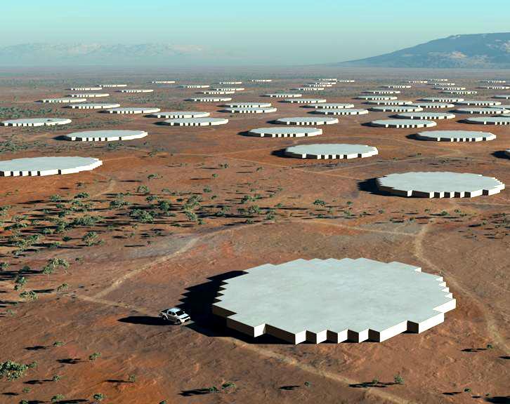
2 SKA Top-level description A large radio telescope for transformational science Up to 1 million m 2 collecting area Operating from 70 MHz to 10 GHz (4m-3cm) Two or more detector technologies Connected to a signal processor and high performance computing system by an optical fibre network Providing 40 x sensitivity of the EVLA, and up to 100,000 x survey speed


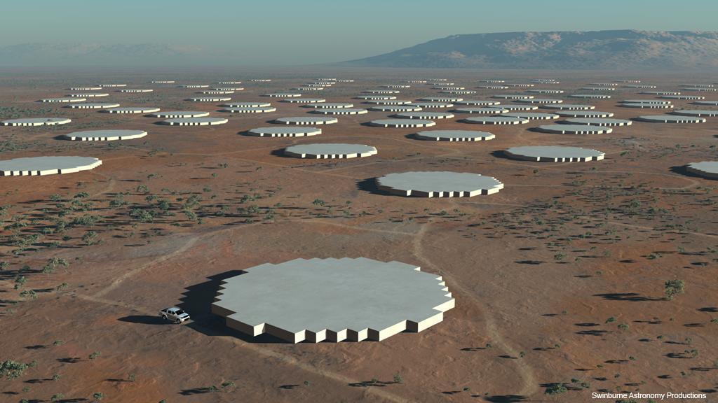
3 SKA 1 Receptor Technologies ~250 Dishes One Core reserved for SKA 2 use. 2-Core Central Region AA-low - 50 arrays Artists Renditions from Swinburne Astronomy Productions


4 SKA 2 Receptor Technologies 250 Dense Aperture Arrays Dishes 3-Core Central Region AA-low Arrays Artist renditions from Swinburne Astronomy Productions

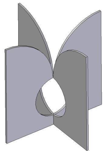
5 Aperture Arrays Michael Kramer
6 Sparse or Dense. Dense: Element spacing λ/2 Fully sampled wavefront Regular layout pattern Constant A eff Excellent side lobe control Beam performance equiv to the best dish design Sparse: Element spacing >λ/2 A eff increases as λ 2 (~ λ 2 /4) Layout irregular to control grating lobes Increased skynoise from grating lobes Possible dynamic range issues
7 Sky Temperature, T sky, K Sparse and Dense regimes Sky Noise Temperature Sky dominated noise Receiver dominated noise ,000 1,200 1,400 1,600 1,800 2,000 Frequency MHz
8 Why aperture arrays? At low frequencies, <~300MHz, the only realistic way of building sufficient collecting area Unsurpassed ability to create Field of View through multiple beams Extremely flexible in observational parameters e.g. Sky area vs. bandwidth Can run multiple experiments concurrently Using a large amount of up front processing they reduce the backend processing load Can tune imaging coverage, beam size, post-processing load etc. ICT based AAs provide many new opportunities


9 An SKA collector summary SKA 1 Freq. Range Collector Sensitivity Number / size Distribution 70 MHz to 450 MHz 300 MHz to 3 GHz AA-low Sparse AA Dishes with single pixel feed 1,000 m 2 /K at 100 MHz 1,000 m 2 /K at 1.4 GHz 50 arrays, Diameter 180 m 70% within 5 km dia., 250 dishes Diameter 15 m 30 % along 3 spiral arms out to 100 km radius SKA 2 Freq. Range Collector Sensitivity Number / size Distribution 70 MHz to 450 MHz 400 MHz to 1.45 GHz 300/1000 MHz to 10 GHz AA-low Sparse AA AA-mid Dense AA Dishes with single pixel feed + PAF 4,000 m 2 /K at 100 MHz 10,000 m 2 /K at 800 MHz 10,000 m 2 /K at 1.4 GHz 250 arrays, Diameter 180 m 250 arrays, Diameter 56 m dishes Diameter 15 m 66% within 5 km dia., 34% along 5 spiral arms out to 180 km radius 50% within 5 km dia, 30% 5km km 20% 180 km-3,000 km.


10 SKA 2 wide area data flow GHz Wide FoV MHz Wide FoV GHz WB-Single Pixel feeds Dense AA.... Sparse AA Aperture Array Station Tile & Station Processing DSP... Central Processing Facility - CPF 16 Tb/s To 250 AA Stations 4 Pb/s Correlator UV s Image formation Archive Data Time Control 20 Gb/s 16 Tb/s Optical Data links AA slice AA slice... Dish & AA+Dish Correlation AA slice 24 Pb/s Tb/s Data switch... Imaging s Tb/s Gb/s Gb/s Control s & User interface Data Archive Science s 15m Dishes DSP Gb/s... Time Standard To 1200 Dishes User interface via Internet


11 Survey speed Fixed Simple survey speed: Survey speed w/bw: ( A eff /T) 2 Ω ( A eff /T) 2 ΩΔν Critical for the SKA a discovery instrument Station data rate, DR st : N beams Ω Δν Total data rate, Dr tot : For fixed Aeff N stn * DR stn Station dia. D (N stn ) -0.5 & Ω stn D -2 Hence A eff Effective collecting area, m 2 T System temperature, K Ω Field of View. deg 2 Δν Bandwidth, Hz Total data rate for a fixed survey speed is independent of # of stations (fixed A eff & Bandwidth)

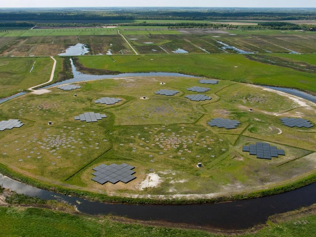
12 LOFAR


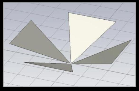
13 AA-low element development Toothed logperiodic antennas for pattern improvement BLU antenna: Bow-tie Low Freq. Ultra-Wideband antenna Pattern measure


14 AA-low elements & array
 Clamp type rotational adjustment Single pole fixing just sunk into ground Buried")
15 LWA element: mechanical example Electronics at top well away from floods etc. Simple skeleton elements (delivered flat) Clamp type rotational adjustment Single pole fixing just sunk into ground Buried cables Easy and quick deployment Cheap mesh groundplane

16 AA-mid Array


17 AA-mid elements and array ORA array - SKADS Vivaldi array - EMBRACE Dense array design, largely decided, select: Element pitch for frequency range & element type Element type and construction technique LNA: differential or single ended
18 TH_n Comms in generic AA with 2-stage beamforming Ae Ae Ae 1.4GHz analogue TH_1 TH_0 Tile - hi Tile - lo 12 fibre each Station Typical: AA-hi tiles: 300 AA-lo tiles: 45 Total: 345 I/p data rate: 42Tb/s 12 fibre each Long distance drivers Long distance drivers e/ oe/ oe/ oe/ o 10Gb/s fibre To Correlator 0.5 GHz analogue TL_0 TL_1 TL_m Max 4 Station s Distributed to all processors in the Station Station control processors Station n To Central control systems Local Processing e.g. Cal; pulsars Long distance drivers..
19 Cooling 2-Pol Elements... Copper Element Digitisation Fibre Element Digitisation Tile Digitisation Tile RFI Digitisation Shielded Element Data C & M Station Processing RFI shielded Station Beams Control & Monitoring... 2x 500MHz Analogue + power Front-end Conventional AA-low Station Clock Element Digitisation... Power Distribution System clock To Correlator & Services Power Grid

20 Delay 1-D Beamforming Incoming signal Array width Elements t Beam Electronic Delay 0 Element #
21 Two stage beamforming Station beams Central perfect beam Tile beam Filling Tile beams with station beams leads to discontinuities in the beamforming for off-centre beams Incoming signal Elements Electronic Delay Tiles Station processor Beam Can be resolved with higher data rate Tile to Station tdelay Tile Beam 0 Element #

22 6 x 120Gb/s 6 x 120Gb/s To Element Digitisation Each link is 12 fibre lanes@10gb/s Station processor Primary Station Board 0 Primary Station Board 1.. Primary Station Board (max 35) Each link is 12 fibre lanes@10gb/s Station All to All Connections Hierarchical structure: Linked with comms Secondary Station Board 0 Secondary Station Board 1.. Secondary Station Board (max 35) Long distance drivers Long distance drivers Long distance drivers Optical links To Correlator 12-channel Rx module. e.g Avago AFBR-820BXXZ To Element digitisation or Primary Station s Each link is 12 fibre lanes@10gb/s Total Raw input data rate: 4.32Tb/s Requirements: High bandwidth in High bandwidth out Largely cross connected Scaleable at various levels Programmable beamforming PChip PChip PChip PChip PChip PChip Each link is 12 diff. copper lanes@10gb/s All to All Connections PChip PChip PChip PChip PChip PChip PChip 20 TMAC Control Line Tx/Rx 12-channel Tx module. e.g Avago AFBR-810BXXZ To Secondary Station s or long distance fibre drivers Each link is 12 fibre lanes@10gb/s Total Raw output data rate: 4.32Tb/s max Station Control
23 Output data rate & array performance The output data rate defines the performance of the array A better measure than beams since it considers flexible use of data between bandwidth and direction. Front end analogue beamforming restricts areas of sky that can be observed concurrently Changing the number of bits/sample for different observation types maximises performance Not a problem for the correlator which only sees total data rate Post-processor needs to interpret blocks of data Build flexibility into the Station processor
24 Potential AA-low station design 1. There are 11,264 dual polarisation elements in a station; 2. Station diameter is 180m; 3. There is no analogue beamforming, every element is digitised; 4. The digitisation is in 44 Tiles of 256 elements each; 5. Data rate off each digitisation box set at 240Gb/s, after some beamforming; 6. The full active bandwidth from the digitisers is returned to the central processor; 7. A station has 22,400 digital receiver channels.
25 AA-low station signal path Element assembly Digitisation box Station Processing Antenna LNA Gain Block ADC comms Analog conditioning ADC Digitisation Processing Primary Station Processing Secondary Station Processing To Correlator Control Signal Transport Clock Distribution Tile station processor optical comms optical interconnect Wide area optical comms Copper: ~20m, 500MHz Optical: ~200m, 10Gb/s Optical: <20m, 120Gb/s

26 Standalone SKA-low element (option) Elements: MHz Solar panel ADC: 1GS/s Power conditioning Processing m all optical Data Control Energy storage Analogue Sync. Benefits: Integrated single unit No copper connection Easy to deploy Minimum RFI Lightning immunity Challenges: Low total power Integration Manufacturability Packaging No need for digitisation boxes

27 Cooling Stand-alone Elements Self powered element Fibre Station Beams Element Data C & M Clock... Station Processing RFI shielded Control & Monitoring System clock Advanced AA-low Station Single or multiple fibres To Correlator & Services Power Grid
28 AA-mid station design: SKA 2 1. The element pitch is 15 cm (λ/2 at 1GHz); 2. Station diameter is 56m, or ~2500m 2 ; 3. Analogue beamform 4 elements; 4. Tiles are 16x16 dual polarisation elements (2.4m square); 5. Tiles have 128 digitisation channels (256*2/4); 6. Data rate off each Tile set at 120Gb/s 7. A Station has 430 Tiles or 110,000 elements or 220,000 receiver chains. 8. A station has 55,000 digital receiver channels.
29 AA-mid proposed signal path Tile TTD 4-element clusters Tile processing unit Front-end Tile Processing Station Processing Antenna LNA Gain Block Analog Cond. ADC comms RF Beamforming ADC Tile Digital Processing Primary Station Processing Secondary Station Processing To Correlator Tile Local Tile Analogue Signal Transport Clock Distribution optical interconnect Wide area optical comms Tile Element & gain. Phantom power Tile station processor optical comms

30 Summary Comms speed is critical at all levels of the AA system Overall requires multi-km, 100 s m, & 10 s m range comms AAs depend on high speed comms and processing More communications gives more performance Increasing comms rate and more processing is a clear upgrade path AA-mid is very challenging.
March Phased Array Technology. Andrew Faulkner
 Aperture Arrays Michael Kramer Sparse Type of AA selection 1000 Sparse AA-low Sky Brightness Temperature (K) 100 10 T sky A eff Fully sampled AA-mid Becoming sparse Aeff / T sys (m 2 / K) Dense A eff /T
November SKA Low Frequency Aperture Array. Andrew Faulkner
 SKA Phase 1 Implementation Southern Africa Australia SKA 1 -mid 250 15m dia. Dishes 0.4-3GHz SKA 1 -low 256,000 antennas Aperture Array Stations 50 350/650MHz SKA 1 -survey 90 15m dia. Dishes 0.7-1.7GHz
Smart Antennas in Radio Astronomy
 Smart Antennas in Radio Astronomy Wim van Cappellen cappellen@astron.nl Netherlands Institute for Radio Astronomy Our mission is to make radio-astronomical discoveries happen ASTRON is an institute for
Towards SKA Multi-beam concepts and technology
 Towards SKA Multi-beam concepts and technology SKA meeting Meudon Observatory, 16 June 2009 Philippe Picard Station de Radioastronomie de Nançay philippe.picard@obs-nancay.fr 1 Square Kilometre Array:
The SKA New Instrumentation: Aperture Arrays
 The SKA New Instrumentation: Aperture Arrays A. van Ardenne, A.J. Faulkner, and J.G. bij de Vaate Abstract The radio frequency window of the Square Kilometre Array is planned to cover the wavelength regime
Multi-octave radio frequency systems: Developments of antenna technology in radio astronomy and imaging systems
 Multi-octave radio frequency systems: Developments of antenna technology in radio astronomy and imaging systems Professor Tony Brown School of Electrical and Electronic Engineering University of Manchester
All-Digital Wideband Space-Frequency Beamforming for the SKA Aperture Array
 All-Digital Wideband Space-Frequency Beamforming for the SKA Aperture Array Vasily A. Khlebnikov, 44-0865-273302, w.khlebnikov@ieee.org, Kristian Zarb-Adami, 44-0865-273302, kza@astro.ox.ac.uk, Richard
Focal Plane Arrays & SKA
 Focal Plane Arrays & SKA Peter Hall SKA International Project Engineer www.skatelescope.org Dwingeloo, June 20 2005 Outline Today: SKA and antennas Phased arrays and SKA Hybrid SKA possibilities» A hybrid
2-PAD: An Introduction. The 2-PAD Team
 2-PAD: An Introduction The 2-PAD Team Workshop, Jodrell Bank, 10 Presented th November 2009 by 2-PAD: Dr An Georgina Introduction Harris Georgina Harris for the 2-PAD Team 1 2-PAD Objectives Demonstrate
Overview of the SKA. P. Dewdney International SKA Project Engineer Nov 9, 2009
 Overview of the SKA P. Dewdney International SKA Project Engineer Nov 9, 2009 Outline* 1. SKA Science Drivers. 2. The SKA System. 3. SKA technologies. 4. Trade-off space. 5. Scaling. 6. Data Rates & Data
Memo 65 SKA Signal processing costs
 Memo 65 SKA Signal processing costs John Bunton, CSIRO ICT Centre 12/08/05 www.skatelescope.org/pages/page_memos.htm Introduction The delay in the building of the SKA has a significant impact on the signal
Integrated receivers for mid-band SKA. Suzy Jackson Engineer, Australia Telescope National Facility
 Integrated receivers for mid-band SKA Suzy Jackson Engineer, Australia Telescope National Facility SKADS FP6 Meeting Chateau de Limelette 4-6 November, 2009 Talk overview Mid band SKA receiver challenges
Integrated receivers for mid-band SKA. Suzy Jackson Engineer, Australia Telescope National Facility
 Integrated receivers for mid-band SKA Suzy Jackson Engineer, Australia Telescope National Facility ASKAP/SKA Special Technical Brief 23 rd October, 2009 Talk overview Mid band SKA receiver challenges ASKAP
A Multi-Fielding SKA Covering the Range 100 MHz 22 GHz. Peter Hall and Aaron Chippendale, CSIRO ATNF 24 November 2003
 A Multi-Fielding SKA Covering the Range 100 MHz 22 GHz Peter Hall and Aaron Chippendale, CSIRO ATNF 24 November 2003 1. Background Various analyses, including the recent IEMT report [1], have noted that
Technology Drivers, SKA Pathfinders P. Dewdney
 Technology Drivers, SKA Pathfinders P. Dewdney Dominion Radio Astrophysical Observatory Herzberg Institute of Astrophysics National Research Council Canada National Research Council Canada Conseil national
Phased Array Feeds & Primary Beams
 Phased Array Feeds & Primary Beams Aidan Hotan ASKAP Deputy Project Scientist 3 rd October 2014 CSIRO ASTRONOMY AND SPACE SCIENCE Outline Review of parabolic (dish) antennas. Focal plane response to a
SKA technology: RF systems & signal processing. Mike Jones University of Oxford
 SKA technology: RF systems & signal processing Mike Jones University of Oxford SKA RF processing Dish receivers Cryogenics RF electronics Fast sampling Antenna processing AA receivers RF gain chain Sampling/antenna
Aperture Arrays for the SKA: the SKADS White Paper
 Design Study 8 Task 1 Deliverable 0.5 : DS White Paper Authors The SKADS Teams System Group: Andrew Faulkner (Chair) Steve Torchinsky Paul Alexander Steve Rawlings Dion Kant Stelio Montebugnoli Philippe
Phased Array Feeds for the SKA. WP2.2.3 PAFSKA Consortium CSIRO ASTRON DRAO NRAO BYU OdP Nancay Cornell U Manchester
 Phased Array Feeds for the SKA WP2.2.3 PAFSKA Consortium CSIRO ASTRON DRAO NRAO BYU OdP Nancay Cornell U Manchester Dish Array Hierarchy Dish Array L5 Elements PAF Dish Single Pixel Feeds L4 Sub systems
Phased Array Feed Design. Stuart Hay 23 October 2009
 Phased Array Feed Design Stuart Hay 23 October 29 Outline Why phased array feeds (PAFs) for radioastronomy? General features and issues of PAF approach Connected-array PAF approach in ASKAP Why PAFs? High
Memo 111. SKADS Benchmark Scenario Design and Costing 2 (The SKA Phase 2 AA Scenario)
") Memo 111 SKADS Benchmark Scenario Design and Costing 2 (The SKA Phase 2 AA Scenario) R. Bolton G. Harris A. Faulkner T. Ikin P. Alexander M. Jones S. Torchinsky D. Kant A. van Ardenne D. Kettle P. Wilkinson
Memo 111 SKADS Benchmark Scenario Design and Costing 2 (The SKA Phase 2 AA Scenario) R. Bolton G. Harris A. Faulkner T. Ikin P. Alexander M. Jones S. Torchinsky D. Kant A. van Ardenne D. Kettle P. Wilkinson
SKA station cost comparison
 SKA station cost comparison John D. Bunton, CSIRO Telecommunications and Industrial Physics 4 August 2003 Introduction Current SKA white papers and updates present cost in a variety of ways which makes
NRC Herzberg Astronomy & Astrophysics
 NRC Herzberg Astronomy & Astrophysics SKA Pre-Construction Update Séverin Gaudet, Canadian Astronomy Data Centre David Loop, Director Astronomy Technology June 2016 update SKA Pre-Construction NRC Involvement
Phased Array Feeds A new technology for multi-beam radio astronomy
 Phased Array Feeds A new technology for multi-beam radio astronomy Aidan Hotan ASKAP Deputy Project Scientist 2 nd October 2015 CSIRO ASTRONOMY AND SPACE SCIENCE Outline Review of radio astronomy concepts.
Dense Aperture Array for SKA
 Dense Aperture Array for SKA Steve Torchinsky EMBRACE Why a Square Kilometre? Detection of HI in emission at cosmological distances R. Ekers, SKA Memo #4, 2001 P. Wilkinson, 1991 J. Heidmann, 1966! SKA
The Australian SKA Pathfinder Project. ASKAP Digital Signal Processing Systems System Description & Overview of Industry Opportunities
 The Australian SKA Pathfinder Project ASKAP Digital Signal Processing Systems System Description & Overview of Industry Opportunities This paper describes the delivery of the digital signal processing
The AAMID consortium: Mid Frequency Aperture Array
 The consortium: Mid Frequency Aperture Array Wim van Cappellen, Consortium Lead Livingstone curves Brought to our attention by Ron Ekers Technological capability leads to discovery in astronomy A single
Detector Systems. Graeme Carrad
 Detector Systems Graeme Carrad November 2011 The Basic Structure of a typical Radio Telescope Antenna Receiver Conversion Digitiser Signal Processing / Correlator They are much the same CSIRO. Radiotelescope
SKA1 low Baseline Design: Lowest Frequency Aspects & EoR Science
 SKA1 low Baseline Design: Lowest Frequency Aspects & EoR Science 1 st science Assessment WS, Jodrell Bank P. Dewdney Mar 27, 2013 Intent of the Baseline Design Basic architecture: 3-telescope, 2-system
Antenna and Analog Beamformer
 Antenna and Analog Beamformer Requirements The antenna system is responsible for collecting radiation from the sky and presenting a suitably conditioned 80-300 MHz RF signal to the receiver node. Because
Correlator Development at Haystack. Roger Cappallo Haystack-NRAO Technical Mtg
 Correlator Development at Haystack Roger Cappallo Haystack-NRAO Technical Mtg. 2006.10.26 History of Correlator Development at Haystack ~1973 Mk I 360 Kb/s x 2 stns. 1981 Mk III 112 Mb/s x 4 stns. 1986
Instrument Requirements and Options for Meeting the Science Opportunities MHz P. Dewdney A. Gray, B. Veidt
 Instrument Requirements and Options for Meeting the Science Opportunities 300-3000 MHz P. Dewdney A. Gray, B. Veidt Dominion Radio Astrophysical Observatory Herzberg Institute of Astrophysics National
Phased Array Feeds for Parkes. Robert Braun Science with 50 Years Young
 Phased Array Feeds for Parkes Robert Braun Science with Parkes @ 50 Years Young Outline PAFs in the SKA context PAFSKA activities Apertif, BYU, NRAO, NAIC, DRAO, ASKAP ASKAP PAF MkI ASKAP PAF MkII Parkes:
Active Impedance Matched Dual-Polarization Phased Array Feed for the GBT
 Active Impedance Matched Dual-Polarization Phased Array Feed for the GBT Karl F. Warnick, David Carter, Taylor Webb, Brian D. Jeffs Department of Electrical and Computer Engineering Brigham Young University,
Roshene McCool Domain Specialist in Signal Transport and Networks SKA Program Development Office
 Roshene McCool Domain Specialist in Signal Transport and Networks SKA Program Development Office mccool@skatelescope.org SKA A description Outline Specifications Long Baselines in the SKA Science drivers
Phased Array Feeds A new technology for wide-field radio astronomy
 Phased Array Feeds A new technology for wide-field radio astronomy Aidan Hotan ASKAP Project Scientist 29 th September 2017 CSIRO ASTRONOMY AND SPACE SCIENCE Outline Review of radio astronomy concepts
Focal Plane Array Beamformer for the Expanded GMRT: Initial
 Focal Plane Array Beamformer for the Expanded GMRT: Initial Implementation on ROACH Kaushal D. Buch Digital Backend Group, Giant Metrewave Radio Telescope, NCRA-TIFR, Pune, India kdbuch@gmrt.ncra.tifr.res.in
An FPGA-Based Back End for Real Time, Multi-Beam Transient Searches Over a Wide Dispersion Measure Range
 An FPGA-Based Back End for Real Time, Multi-Beam Transient Searches Over a Wide Dispersion Measure Range Larry D'Addario 1, Nathan Clarke 2, Robert Navarro 1, and Joseph Trinh 1 1 Jet Propulsion Laboratory,
BRAND EVN AND EVN) (BRoad-bAND Joint Research Activity in RadioNet4 Gino Tuccari & Walter Alef plus partners
 (BRoad-bAND Joint Research Activity in RadioNet4 Gino Tuccari & Walter Alef plus partners") BRAND EVN (BRoad-b AND EVN) (BRoad-bAND Joint Research Activity in RadioNet4 Gino Tuccari & Walter Alef plus partners digital VLBI-receiver: ~1.5-15.5 GHz for the EVN and other telescopes Prototype for
BRAND EVN (BRoad-b AND EVN) (BRoad-bAND Joint Research Activity in RadioNet4 Gino Tuccari & Walter Alef plus partners digital VLBI-receiver: ~1.5-15.5 GHz for the EVN and other telescopes Prototype for
Green Bank Instrumentation circa 2030
 Green Bank Instrumentation circa 2030 Dan Werthimer and 800 CASPER Collaborators http://casper.berkeley.edu Upcoming Nobel Prizes with Radio Instrumentation Gravitational Wave Detection (pulsar timing)
Radio Astronomy Transformed
 Radio Astronomy Transformed - Aperture Arrays: Past, Present & Future Prof. Michael Garrett ASTRON, the Netherlands Institute for Radio Astronomy Leiden University. Mike Garrett / NAC 1 Early Antenna Arrays
THE KAROO ARRAY TELESCOPE (KAT) & FPA EFFORT IN SOUTH AFRICA
 & FPA EFFORT IN SOUTH AFRICA") THE KAROO ARRAY TELESCOPE (KAT) & FPA EFFORT IN SOUTH AFRICA Dr. Dirk Baker (KAT FPA Sub-system Manager) Prof. Justin Jonas (SKA SA Project Scientist) Ms. Anita Loots (KAT Project Manager) Mr. David de
THE KAROO ARRAY TELESCOPE (KAT) & FPA EFFORT IN SOUTH AFRICA Dr. Dirk Baker (KAT FPA Sub-system Manager) Prof. Justin Jonas (SKA SA Project Scientist) Ms. Anita Loots (KAT Project Manager) Mr. David de
Photonic Integrated Beamformer for Broadband Radio Astronomy
 M. Burla, D. A. I. Marpaung, M. R. H. Khan, C. G. H. Roeloffzen Telecommunication Engineering group University of Twente, Enschede, The Netherlands P. Maat, K. Dijkstra ASTRON, Dwingeloo, The Netherlands
ASKAP Industry technical briefing. Tim Cornwell, ASKAP Computing Project Lead Australian Square Kilometre Array Pathfinder
 ! ASKAP Industry technical briefing Tim Cornwell, ASKAP Computing Project Lead Australian Square Kilometre Array Pathfinder The Square Kilometre Array 2020 era radio telescope Very large collecting area
SKA-low and the Aperture Array Verification System
 SKA-low and the Aperture Array Verification System Randall Wayth AADCC Project Scientist On behalf of the Aperture Array Design & Construction Consortium (AADCC) AADCC partners ASTRON (Netherlands) ICRAR/Curtin
Memo 130. SKA Phase 1: Preliminary System Description
 Memo 130 SKA Phase 1: Preliminary System Description P. Dewdney (SPDO) J-G bij de Vaate (ASTRON) K. Cloete (SPDO) A. Gunst (ASTRON) D. Hall (SPDO) R. McCool (SPDO) N. Roddis (SPDO) W. Turner (SPDO) November
BRAND EVN EVN) Joint Research Activity in RadioNet4 Gino Tuccari & Walter Alef plus partners
 Joint Research Activity in RadioNet4 Gino Tuccari & Walter Alef plus partners") BRAND EVN (BRoad-bAND EVN) Joint Research Activity in RadioNet4 Gino Tuccari & Walter Alef plus partners EVN Observing Bands < 22GHz Today in the EVN separate receivers cover: 18 cm - L band 13 cm - S
BRAND EVN (BRoad-bAND EVN) Joint Research Activity in RadioNet4 Gino Tuccari & Walter Alef plus partners EVN Observing Bands < 22GHz Today in the EVN separate receivers cover: 18 cm - L band 13 cm - S
Technologies for Radio Astronomy Mark Bowen Acting Theme Leader Technologies for Radio Astronomy October 2012 CSIRO ASTRONOMY AND SPACE SCIENCE
 Technologies for Radio Astronomy Mark Bowen Acting Theme Leader Technologies for Radio Astronomy October 2012 CSIRO ASTRONOMY AND SPACE SCIENCE Outline Current Projects CABB ATCA C/X Upgrade FAST Parkes
Receivers for. FFRF Tutorial by Tom Clark, NASA/GSFC & NVI Wettzell, March 19, 2009
 Receivers for VLBI2010 FFRF Tutorial by Tom Clark, NASA/GSFC & NVI Wettzell, March 19, 2009 There is no fundamental difference between the receivers for PRIME FOCUS & CASSEGRAIN Except for: the beamwidth
The CASPER Hardware Platform. Richard Armstrong
 The CASPER Hardware Platform Richard Armstrong Outline Radio Telescopes and processing Backends: How they have always been done How they should be done CASPER System: a pretty good stab at how things should
Technologies for Radio Astronomy
 Technologies for Radio Astronomy CSIRO Astronomy and Space Science Alex Dunning in lieu of Tasso Tzioumis Facilities Program Director Technologies June 2017 Directions for ATNF Engineering (Update since
Components of Imaging at Low Frequencies: Status & Challenges
 Components of Imaging at Low Frequencies: Status & Challenges Dec. 12th 2013 S. Bhatnagar NRAO Collaborators: T.J. Cornwell, R. Nityananda, K. Golap, U. Rau J. Uson, R. Perley, F. Owen Telescope sensitivity
More Radio Astronomy
 More Radio Astronomy Radio Telescopes - Basic Design A radio telescope is composed of: - a radio reflector (the dish) - an antenna referred to as the feed on to which the radiation is focused - a radio
BRAND EVN (BRoad-bAND EVN) Joint Research Activity in RadioNet4 Gino Tuccari & Walter Alef plus partners
 Joint Research Activity in RadioNet4 Gino Tuccari & Walter Alef plus partners") BRAND EVN (BRoad-bAND EVN) Joint Research Activity in RadioNet4 Gino Tuccari & Walter Alef plus partners digital VLBI-receiver: ~1.5-15.5 GHz for the EVN and other telescopes Prototype for prime focus
BRAND EVN (BRoad-bAND EVN) Joint Research Activity in RadioNet4 Gino Tuccari & Walter Alef plus partners digital VLBI-receiver: ~1.5-15.5 GHz for the EVN and other telescopes Prototype for prime focus
Scalable Front-End Digital Signal Processing for a Phased Array Radar Demonstrator. International Radar Symposium 2012 Warsaw, 24 May 2012
 Scalable Front-End Digital Signal Processing for a Phased Array Radar Demonstrator F. Winterstein, G. Sessler, M. Montagna, M. Mendijur, G. Dauron, PM. Besso International Radar Symposium 2012 Warsaw,
Radio Astronomy: SKA-Era Interferometry and Other Challenges. Dr Jasper Horrell, SKA SA (and Dr Oleg Smirnov, Rhodes and SKA SA)
") Radio Astronomy: SKA-Era Interferometry and Other Challenges Dr Jasper Horrell, SKA SA (and Dr Oleg Smirnov, Rhodes and SKA SA) ASSA Symposium, Cape Town, Oct 2012 Scope SKA antenna types Single dishes
Radio Astronomy: SKA-Era Interferometry and Other Challenges Dr Jasper Horrell, SKA SA (and Dr Oleg Smirnov, Rhodes and SKA SA) ASSA Symposium, Cape Town, Oct 2012 Scope SKA antenna types Single dishes
Recent progress and future development of Nobeyama 45-m Telescope
 Recent progress and future development of Nobeyama 45-m Telescope Masao Saito: Director of Nobeyama Radio Observatory Tetsuhiro Minamidani: Nobeyama Radio Observatory Outline Nobeyama 45-m Telescope Recent
EMBRACE DS5 presentation
 EMBRACE presentation Paris 4 th September 2006 ASTRON, The Netherlands Acknowledgement The authors wish to acknowledge the enormous contribution of the whole EMBRACE team presently located at: ASTRON,
The GMRT : a look at the Past, Present and Future
 The GMRT : a look at the Past, Present and Future Yashwant Gupta & Govind Swarup National Centre for Radio Astrophysics Pune India URSI GASS Montreal 2017 The GMRT : a look at the Past, Present and Future
Multi-Mode Antennas for Hemispherical Field-of-View Coverage
 Multi-Mode Antennas for Hemispherical Field-of-View Coverage D.S. Prinsloo P. Meyer R. Maaskant M.V. Ivashina Dept. of Electrical and Electronic Engineering Dept. of Signals and Systems Stellenbosch, South
Data Digitization & Transmission Session Moderator: Chris Langley
 Data Digitization & Transmission Session Moderator: Chris Langley Atacama Large Millimeter/submillimeter Array Karl G. Jansky Very Large Array Robert C. Byrd Green Bank Telescope Very Long Baseline Array
OPTICS OF SINGLE BEAM, DUAL BEAM & ARRAY RECEIVERS ON LARGE TELESCOPES J A M E S W L A M B, C A L T E C H
 OPTICS OF SINGLE BEAM, DUAL BEAM & ARRAY RECEIVERS ON LARGE TELESCOPES J A M E S W L A M B, C A L T E C H OUTLINE Antenna optics Aberrations Diffraction Single feeds Types of feed Bandwidth Imaging feeds
LOFAR: Special Issues
 Netherlands Institute for Radio Astronomy LOFAR: Special Issues John McKean (ASTRON) ASTRON is part of the Netherlands Organisation for Scientific Research (NWO) 1 Preamble http://www.astron.nl/~mckean/eris-2011-2.pdf
The Future: Ultra Wide Band Feeds and Focal Plane Arrays
 The Future: Ultra Wide Band Feeds and Focal Plane Arrays Germán Cortés-Medellín NAIC Cornell University 1-1 Overview Chalmers Feed Characterization of Chalmers Feed at Arecibo Focal Plane Arrays for Arecibo
Phased Array Feed (PAF) Design for the LOVELL Antenna based on the Octagonal Ring Antenna (ORA) Array
 Design for the LOVELL Antenna based on the Octagonal Ring Antenna (ORA) Array") Phased Array Feed (PAF) Design for the LOVELL Antenna based on the Octagonal Ring Antenna (ORA) Array M. Yang, D. Zhang, L. Danoon and A. K. Brown, School of Electrical and Electronic Engineering The University
Phased Array Feed (PAF) Design for the LOVELL Antenna based on the Octagonal Ring Antenna (ORA) Array M. Yang, D. Zhang, L. Danoon and A. K. Brown, School of Electrical and Electronic Engineering The University
S.A. Torchinsky, A. van Ardenne, T. van den Brink-Havinga, A.J.J. van Es, A.J. Faulkner (eds.) 4-6 November 2009, Château de Limelette, Belgium
 4-6 November 2009, Château de Limelette, Belgium") WIDEFIELD SCIENCE AND TECHNOLOGY FOR THE SKA SKADS CONFERENCE 29 S.A. Torchinsky, A. van Ardenne, T. van den Brink-Havinga, A.J.J. van Es, A.J. Faulkner (eds.) 4-6 November 29, Château de Limelette, Belgium
WIDEFIELD SCIENCE AND TECHNOLOGY FOR THE SKA SKADS CONFERENCE 29 S.A. Torchinsky, A. van Ardenne, T. van den Brink-Havinga, A.J.J. van Es, A.J. Faulkner (eds.) 4-6 November 29, Château de Limelette, Belgium
HR001118S0020 Millimeter-Wave Digital Arrays (MIDAS) Frequently Asked Questions (FAQ) March 12, 2018
 Frequently Asked Questions (FAQ) March 12, 2018") HR001118S0020 Millimeter-Wave Digital Arrays (MIDAS) Frequently Asked Questions (FAQ) March 12, 2018 Q1: Will there be multiple awards? A1: Yes, multiple awards are expected (page 4 of BAA). Q2: Will there
HR001118S0020 Millimeter-Wave Digital Arrays (MIDAS) Frequently Asked Questions (FAQ) March 12, 2018 Q1: Will there be multiple awards? A1: Yes, multiple awards are expected (page 4 of BAA). Q2: Will there
An Accurate phase calibration Technique for digital beamforming in the multi-transceiver TIGER-3 HF radar system
 An Accurate phase calibration Technique for digital beamforming in the multi-transceiver TIGER-3 HF radar system H. Nguyen, J. Whittington, J. C Devlin, V. Vu and, E. Custovic. Department of Electronic
Very Long Baseline Interferometry
 Very Long Baseline Interferometry Cormac Reynolds, JIVE European Radio Interferometry School, Bonn 12 Sept. 2007 VLBI Arrays EVN (Europe, China, South Africa, Arecibo) VLBA (USA) EVN + VLBA coordinate
HR001118S0020 Millimeter-Wave Digital Arrays (MIDAS) Frequently Asked Questions (FAQ) February 12, 2018
 Frequently Asked Questions (FAQ) February 12, 2018") HR001118S0020 Millimeter-Wave Digital Arrays (MIDAS) Frequently Asked Questions (FAQ) February 12, 2018 Q1: Will there be multiple awards? A1: Yes, multiple awards are expected (page 4 of BAA). Q2: Will
HR001118S0020 Millimeter-Wave Digital Arrays (MIDAS) Frequently Asked Questions (FAQ) February 12, 2018 Q1: Will there be multiple awards? A1: Yes, multiple awards are expected (page 4 of BAA). Q2: Will
THE purpose of beamforming is to precisely align the
 1 Beamforming Techniques for Large-N Aperture Arrays K. Zarb-Adami, A. Faulkner, J.G. Bij de Vaate, G.W. Kant and P.Picard arxiv:1008.4047v1 [astro-ph.im] 24 Aug 2010 Abstract Beamforming is central to
SKA Phase 1: Costs of Computation. Duncan Hall CALIM 2010
 SKA Phase 1: Costs of Computation Duncan Hall CALIM 2010 2010 August 24, 27 Outline Motivation Phase 1 in a nutshell Benchmark from 2001 [EVLA Memo 24] Some questions Amdahl s law overrides Moore s law!
Radio Interferometers Around the World. Amy J. Mioduszewski (NRAO)
") Radio Interferometers Around the World Amy J. Mioduszewski (NRAO) A somewhat biased view of current interferometers Limited to telescopes that exist or are in the process of being built (i.e., I am not
Radio Interferometers Around the World Amy J. Mioduszewski (NRAO) A somewhat biased view of current interferometers Limited to telescopes that exist or are in the process of being built (i.e., I am not
Why Single Dish? Darrel Emerson NRAO Tucson. NAIC-NRAO School on Single-Dish Radio Astronomy. Green Bank, August 2003.
 Why Single Dish? Darrel Emerson NRAO Tucson NAIC-NRAO School on Single-Dish Radio Astronomy. Green Bank, August 2003. Why Single Dish? What's the Alternative? Comparisons between Single-Dish, Phased Array
Detection of Radio Pulses from Air Showers with LOPES
 Detection of Radio Pulses from Air Showers with LOPES Andreas Horneffer for the LOPES Collaboration Radboud University Nijmegen Radio Emission from Air Showers air showers are known since 1965 to emit
Array noise temperature measurements at the Parkes PAF Test-bed Facility
 Array noise temperature measurements at the Parkes PAF Test-bed Facility Douglas B. Hayman, Aaron P. Chippendale, Robert D. Shaw and Stuart G. Hay MIDPREP 1 April 2014 COMPUTATIONAL INFORMATICS ASTRONOMY
VLBI2010: In search of Sub-mm Accuracy
 VLBI2010: In search of Sub-mm Accuracy Bill Petrachenko, Nov 6, 2007, University of New Brunswick What is VLBI2010? VLBI2010 is an effort by the International VLBI Service for Geodesy and Astrometry (IVS)
RAPID A Portable and Reconfigurable Imaging Interferometer Array
 RAPID A Portable and Reconfigurable Imaging Interferometer Array Colin Lonsdale, Frank Lind and a team of ~10 MIT Haystack Observatory Cambridge University Team Led by Andy Faulkner JPL Team Led by Chris
Why Single Dish? Why Single Dish? Darrel Emerson NRAO Tucson
 Why Single Dish? Darrel Emerson NRAO Tucson Why Single Dish? What's the Alternative? Comparisons between Single-Dish, Phased Array & Interferometers Advantages and Disadvantages of Correlation Interferometer
MWA Antenna Description as Supplied by Reeve
 MWA Antenna Description as Supplied by Reeve Basic characteristics: Antennas are shipped broken down and require a few minutes to assemble in the field Each antenna is a dual assembly shaped like a bat
New Trends on Receivers Development" May 30, 2005, Medicina. RECEIVING SYSTEMs for the ANTENNAS OPERATED by the INSTITUTE of RADIOASTRONOMY in ITALY
 New Trends on Receivers Development" May 30, 2005, Medicina RECEIVING SYSTEMs for the ANTENNAS OPERATED by the INSTITUTE of RADIOASTRONOMY in ITALY Alessandro Orfei IRA-INAF, Medicina station (Italy) RADIONET
Chapter 5. Array of Star Spirals
 Chapter 5. Array of Star Spirals The star spiral was introduced in the previous chapter and it compared well with the circular Archimedean spiral. This chapter will examine the star spiral in an array
Final Feed Selection Study For the Multi Beam Array System
 National Astronomy and Ionosphere Center Arecibo Observatory Focal Array Memo Series Final Feed Selection Study For the Multi Beam Array System By: Germán Cortés-Medellín CORNELL July/19/2002 U n i v e
Wide-Band Imaging. Outline : CASS Radio Astronomy School Sept 2012 Narrabri, NSW, Australia. - What is wideband imaging?
 Wide-Band Imaging 24-28 Sept 2012 Narrabri, NSW, Australia Outline : - What is wideband imaging? - Two Algorithms Urvashi Rau - Many Examples National Radio Astronomy Observatory Socorro, NM, USA 1/32
Specifications for the GBT spectrometer
 GBT memo No. 292 Specifications for the GBT spectrometer Authors: D. Anish Roshi 1, Green Bank Scientific Staff, J. Richard Fisher 2, John Ford 1 Affiliation: 1 NRAO, Green Bank, WV 24944. 2 NRAO, Charlottesville,
Reliability tests and experimental analysis on radioreceiver chains
 IMTC 2006 Instrumentation and Measurement Technology Conference Sorrento, Italy 24-27 Aprile 2006 Candidate for Special Session on INSTRUMENTATION AND MEASUREMENT METHODS FOR AVAILABILITY ANALYSIS OF COMPONENTS
The SKA LOW correlator design challenges
 The SKA LOW correlator design challenges John Bunton CSP System Engineer C4SKA, Auckland, 9-10 February, 2017 CSIRO ASTRONOMY AND SPACE SCIENCE SKA1 Low antenna station (Australia) Station beamforming
S.A. Torchinsky, A. van Ardenne, T. van den Brink-Havinga, A.J.J. van Es, A.J. Faulkner (eds.) 4-6 November 2009, Château de Limelette, Belgium
 4-6 November 2009, Château de Limelette, Belgium") WIDEFIELD SCIENCE AND TECHNOLOGY FOR THE SKA SKADS CONFERENCE 29 S.A. Torchinsky, A. van Ardenne, T. van den Brink-Havinga, A.J.J. van Es, A.J. Faulkner (eds.) 4-6 November 29, Château de Limelette, Belgium
WIDEFIELD SCIENCE AND TECHNOLOGY FOR THE SKA SKADS CONFERENCE 29 S.A. Torchinsky, A. van Ardenne, T. van den Brink-Havinga, A.J.J. van Es, A.J. Faulkner (eds.) 4-6 November 29, Château de Limelette, Belgium
The Phased Array Feed Receiver System : Linearity, Cross coupling and Image Rejection
 The Phased Array Feed Receiver System : Linearity, Cross coupling and Image Rejection D. Anish Roshi 1,2, Robert Simon 1, Steve White 1, William Shillue 2, Richard J. Fisher 2 1 National Radio Astronomy
Focal Plane Array Related Activities at CSIRO
 ICT Centre /antennas Focal Plane Array Related Activities at CSIRO Trevor S. Bird (1), Douglas Hayman (1), Suzy Jackson (2) & Dick Ferris (2) (1) CSIRO ICT Centre (2) CSIRO Australia Telescope National
Beamforming for IPS and Pulsar Observations
 Beamforming for IPS and Pulsar Observations Divya Oberoi MIT Haystack Observatory Sunrise at Mileura P. Walsh Function, Inputs and Outputs Function - combine the voltage signal from each of the 512 tiles
Why Single Dish? Darrel Emerson NRAO Tucson. NAIC-NRAO School on Single-Dish Radio Astronomy. Green Bank, August 2003.
 Why Single Dish? Darrel Emerson NRAO Tucson NAIC-NRAO School on Single-Dish Radio Astronomy. Green Bank, August 2003. Why Single Dish? What's the Alternative? Comparisons between Single-Dish, Phased Array
Tactical COMMS/ESM System for Submarines. A Front-end Perspective
 Tactical COMMS/ESM System for Submarines A Front-end Perspective South African AOC Chapter (Aardvark Roost) Conference 25 th - 26 th August 2009 at CSIR Conference Centre, Pretoria uwe.trautwein@medav.de
Radio Telescope Receivers
 Radio Telescope Receivers Alex Dunning 25 th September 2017 CSIRO ASTRONOMY AND SPACE SCIENCE A radio receiver is an electronic device that receives radio waves and converts the information carried by
5G India Demystifying 5G, Massive MIMO and Challenges
 Demystifying 5G, Massive MIMO and Challenges 5G India 2017 Ramarao Anil Head Product Support, Development & Applications Rohde & Schwarz India Pvt. Ltd. COMPANY RESTRICTED Agenda ı 5G Vision ı Why Virtualization
A Scalable Computer Architecture for
 A Scalable Computer Architecture for On-line Pulsar Search on the SKA - Draft Version - G. Knittel, A. Horneffer MPI for Radio Astronomy Bonn with help from: M. Kramer, B. Klein, R. Eatough GPU-Based Pulsar
A report on KAT7 and MeerKAT status and plans
 A report on KAT7 and MeerKAT status and plans SKA SA, Cape Town Office 3rd Floor, The Park, Park Road, Pinelands, Cape Town, South Africa E mail: tony@hartrao.ac.za This is a short memo on the current
SKA Site Characterisation and Array Configuration; Overview and Status WP Rob Millenaar, SPDO
 SKA Site Characterisation and Array Configuration; Overview and Status WP2 2011 Rob Millenaar, SPDO Site Characterisation 1. Intro SKA Site Characterisation/Selection 2. Request for Information 1. In situ
Modelling and Simulation of Conical Spiral Antennas
 Modelling and Simulation of Conical Spiral Antennas Aziz Jiwani and Shantanu Padhi AAVP workshop University of Cambridge, UK 9 December 2010 Motivation Most antennas are not able to maintain characteristics
Submitted to the SKA Engineering and Management Team by
 Authors: John D. Bunton Carole A. Jackson Elaine M. Sadler CSIRO Telecommunications and Industrial Physics RSAA, Australian National University School of Physics, University of Sydney Submitted to the