Busway Design The Easy Way. By: IIEE-ABU DHABI CHAPTER
|
|
|
- Drusilla Strickland
- 5 years ago
- Views:
Transcription
1 Busway Design The Easy Way By: IIEE-ABU DHABI CHAPTER
2 OBJECTIVES Understand The Busway / Bus Bar Its Best Value / Advantages Common Application How to design
3 DEFINITION BUSWAY is defined by the National Electrical Manufacturers Association (NEMA) as prefabricated electrical distribution system consisting of bus bars in a protective enclosure including straight lengths, fittings, devices and accessories.
4 Reasons to use Busway: Commercial and Industrial distribution systems use various methods to conduct electrical energy. These methods often include heavy conductors run in trays and conduit. Cable and conduit assemblies are time consuming to install. Combining the material and labor, it is costly Once installed they are difficult to change. To eliminate these short comings, power is often distributed using enclosed bus bars, which is referred to, as.....


5 BUSWAY Feeder Busway Plug-In Busway
6 Why Busway is your best value? Today electrical engineers and contractors around the world are specifying busway for more and more industrial and commercial projects. THE REASONS? Busway offers a versatility in application and a simplicity in installation that cables and conduit can not match. More than that, busway offers those benefits, at a total installed cost, very much lower than cable and conduit.
7 Busway is pre-engineered for easy installation with hand tools and, a minimum of equipment. Aside from installation cost, there are more ways busway saves time and money, as follows: 00% reusable. When building s electrical system needs to be modified, entire busway runs can be taken down and relocated. Less downtime. Simple fast installation and relocation means less downtime for the equipment and system powers. Easily expandable. Expanding a system can be done in most cases with standard busway components, mostly available from stock for fasttrack delivery.
8 Lower impedance. The lower impedance of a busway system means there is lower voltage drop than with the cable and conduit, resulting in lower energy cost. Light and compact. Compared to cable and conduit, busway is lighter weight and compact size help to simplify storage, and make handling and installation easier. A high degree of safety. The conductors are totally enclosed and plug-in units are polarized.

9 Busway includes bus bars, an insulating and/or support material, and a housing.

10 Joint Pack Connector Steel Side Channel Polyester Film Insulation Steel Side Channel Aluminum Integral earth Bar Fiber Glass Tape and epoxy Risen Silver or Tin Plated Bus Bar

11 THE TWO BASIC TYPES OF BUSWAY ARE:. Plug-In Busway Versatile and ideal for distributing power over a wide area. It can be used in horizontal and vertical risers. Can be extended at a later time to cater future loads.

12 2. Feeder Busway Feeder busway is for distributing loads concentrated in one area. Used in short runs as a service entrance. As tie run from distribution switchboard to motor control center, or components that demand high concentration of power, such as large motors.
13 OTHER BUSWAY FITTINGS Flanged End Elbow Expansion joint Joint pack Cable Tap Box Reducer Tap Off Unit End Cap or Closure Flanged-End-Transformer Tap (FET) Flexible Link Service Head Transformer Tap 80 Phase Transition
14 BUSWAY FITTINGS FLANGED END Connecting switchboards or transformer Single bolt connection
15

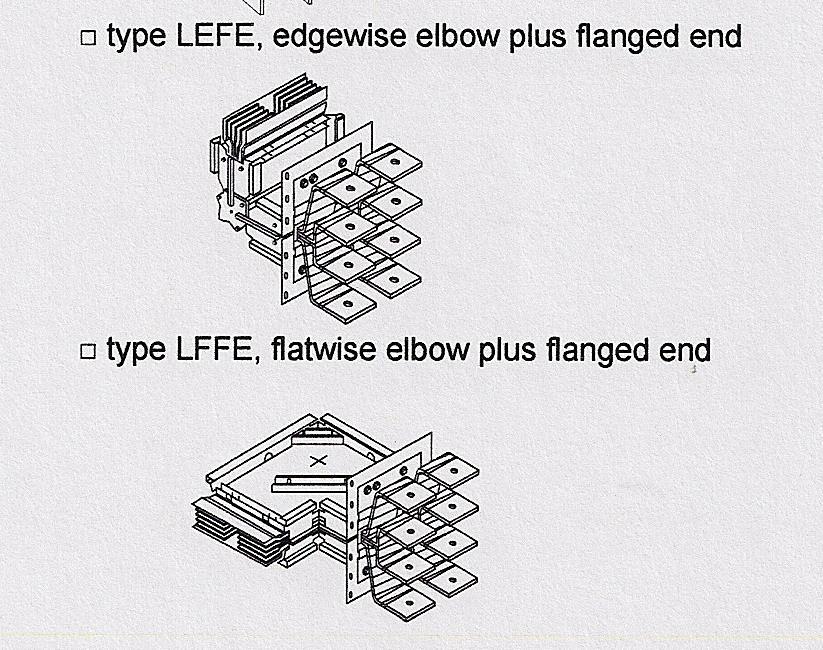
16 ELBOWS Standard connecting angle:90 o Any angles or format according to customer s demand. Provide various elbows combination: Double-elbow, Tee

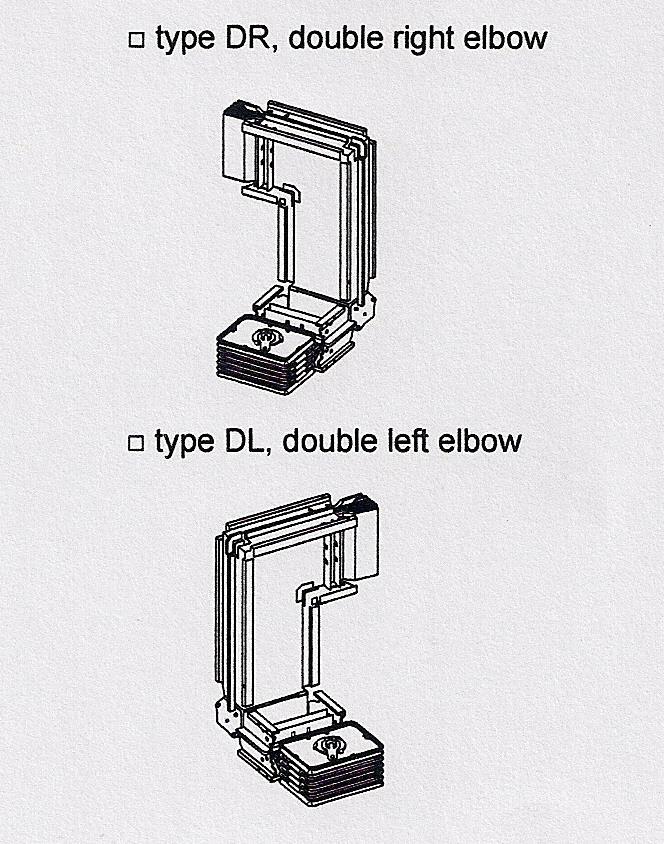
17 DOUBLE ELBOWS

18 EXPANSION JOINT A busbar trunking unit permitting axial movement of the busbar conductors due to the different coefficient of expansion of differing materials


19 JOINT PACK Plated contact surface Adjustable range: +/- 3mm

20 CABLE TAP BOX
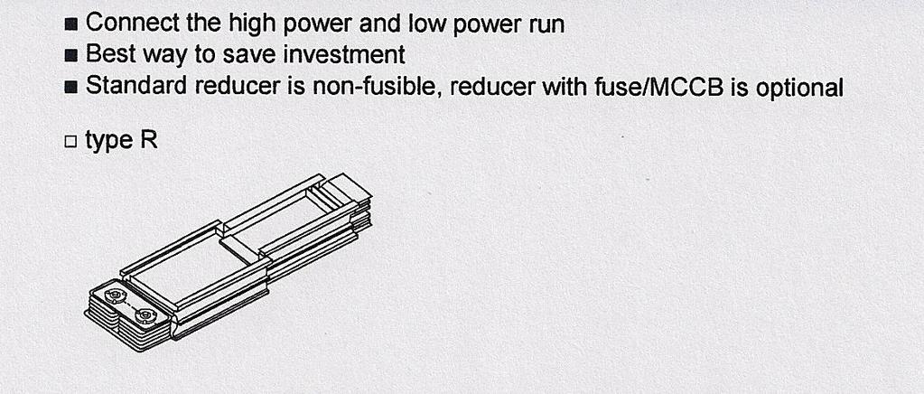
21 REDUCER

22 END CLOSURE The end closure protects and insulates the conductor ends and is fitted to the last plug-in riser section.


23 TAP-OFF UNIT or PLUG-IN UNIT

24 FLANGED END TRANSFORMER TAP
25 TRANSFORMER THROAT CONNECTION

26 FLEXIBLE LINKS
27 BUSWAY MOST COMMON APPLICATION Risers in office / commercial construction Large service entrance feeders High ampere tie runs between equipment Industrial Plug-In Runs

28 OFFICE / COMMERCIAL CONSTRUCTION

29 BURJ KHALIFA - WORLD S TALLEST STRUCTURE

30 PREVIOUS WORLD S TALLEST STRUCTURES WITH BUSWAY

31 The Four Basic Types of Busway Runs - Service Entrance Connections A typical service entrance run from a utility transformer to a switchboard.

32 Transformer - Switchboard Connection Flanged End Feeder Busway Flanged End Flexible Link Flexible Link Switchboard

33 2 - Plug-In Type Horizontal Run A simply Plug-In run fed by a switchboard through a Tee. (Application always indoor.

34 Plug-In Type Horizontal Run Sample of Plug-In Horizontal Run Sample of Service Entrance Run


35 3 - Plug-In Type Vertical Riser A simply plug-in riser fed by a switchboard. (Always an indoor application)

36 Vertical Plug-In Riser
37 4 - Feeder Type Tie Run A typical feeder run between two switchboards. (Always an indoor application)

38 Feeder Type Tie Run
39 DESIGN GUIDE FOR BUSWAY DESIGN ORDER: - Determine the current rating (I b ) 2 - Choosing the busbar trunking rating 3 - Identifying the IPxx Protection 4 - Checking the rating with respect to allowable voltage drop 5 - Checking the rating with respect to short-circuit withstand current 6 - Protecting against bus bar trunking overloads
40 Determine the current rating (I b ): Calculation of the total current (Ib) absorbed by a run is equal to the sum of the currents absorbed by all of the loads. The loads do not all operate at the same time and as they are not continuously at full load, a stacking or simultaneity factor Ks has to be taken into account:

41 Determining by equipment load, coefficient, Ks:
42 Calculation of the total current (Ib) absorbed by one building is equal to the sum of the currents absorbed by all of the loads of all floors. The floors do not all operate at the same time and, as they are not continuously at full loads, a stacking or simultaneity factor K s and K f has to be taken into account:

43 Determining by the floor loads, coefficient, Kf:


44 Sample Busway Run in the following page, feeding 6 to 26 floor of the Building. The load per floor is typical. P TCL = 26.25kW Load per floor :
45 0.8 Load per floor

46 0.9 Total floor loads
47 Remember to take into account future increases of load. A 20% reserve is recommended Selected BUSWAY rating is 2000A

48 2 - Choosing Busway Rating according to Nominal Current In

49 2 - Identifying the IPxx Protection
50 Sample plug-in riser busway design
51 CHECK THE BUSWAY RATING CONSIDERING VOLTAGE DROP requirement in the electrical system. (As general rule, voltage drop should not exceed 4% at the furthest outlet) Calculate the voltage drop based on the TOTAL Calculated load current, Ib
52 4 - Check the rating with respect to allowable VOLTAGE DROP Voltage drop Considerations: Transformer to MDB = 0.5% MDB to Busway =.5 % Busway to SMDB = 2.5% SMDB to FDB = 3% FDB to furthest load = 4% VD avg k L 3 I Ravg avg cos X sin Where: VD = voltage drop of the system (V) I = Current of the system being considered L = length of the busway being considered (meter) k = load distribution factor Power factor, (p.f.) = 0.8 R = average resistance, ohms X = average reactance, ohms
], where R t is the known resistance of the conductor at temperature t")
53 Load Distibution factor, K Busway Impedance values The published resistance is at the test ambient of 25 C. Therefore the resistance must be change due to increase in operating temperature from 80 C to 05 C R t2 = R t x [ + a t x (t2 -t)], where R t is the known resistance of the conductor at temperature t R t2 is the desired resistance of the conductor at temperature t2 a t is the temperature coefficient of resistance at temperature t t2 the desired temperature of the conductor t the known temperature of the conductor aα t C T =80 C T2= 05 C R t (mw/m) R t2 (mw/m) X avg (mw/m) 800A A A A A A
54 Concentrated Load, k factor = VD avg VD avg k L 3 I Ravg avg cos X sin x x0.6 VD avg 7. 54V Distributed Load, k factor = 0.5 VD avg 0.5x x x0.6 VD avg. 6V VDavg V
55 VDavg V Therefore, 2000A busway does not meet the required voltage drop limit of.5%
56 Check voltage drop using, 2500A Concentrated Load, k factor = VD avg VD avg k L 3 I Ravg avg cos X sin x x0.6 VD avg 5. 4V Distributed Load, k factor = 0.5 VD avg 0.5x x x0.6 VD avg 0. 66V
57 VD avg V Therefore, 2500A BUSWAY IS THE CORRECT RATING
58 FACTORS AFFECTING BUSWAY RATING Ambient Temperature Temperature Rise and Harmonics
59 Ambient Temperature: When busway are installed in locations that have temperature above 40 C, the busway should be de-rated in accordance with the manufacturers recommendations, if furnished, or the following table: Ambient Temperature 40 C (04 F) 45 C (3 F) 50 C (22 F) 55 C (3 F) 60 C (40 F) 65 C (49 F) 70 C (58 F) Multiplier
60 Temperature Rise: According to IEC , standard. The maximum temperature rise within the busway should not exceed 55 deg.c rise above ambient temperature of 50 deg.c. What is the effect in the busway, if the rise is 35 deg.c above 50 deg.c ambient temperature?
61 Busway De-rating Due To Temperature Rise Busbar Trunking Derating Based on Square D Busway (I-Line II) General Maximum NEMA Design Ambient Temperature 40 C Maximum UL Design Temperature Rise of Bus Bar 55 C Maximum Total Temperature of Bus Bar - NEMA & UL 95 C Maximum Total Temperature of Bus Bar - Based on Insulation Materials 05 C Estimated Ambient Temperature 50 C Maximum Allowable Operating Temperature 35 C Since From CDA Publication 22, June 996 "Copper for Busbars", page 7 "Where a busbar system is to be used under new current or temperature rise conditions, the following formula can be used to find the new corresponding new temperature rise or current:" I I 2 æ ö ç è 2 ø 0.6 æ a ç è a T T ö ø 0.5 "where, I = current, A I 2 = current 2, A Ø = temperature rise for current, C Ø 2 = temperature rise for current 2, C T = working temperature for current, C T 2 = working temperature for current 2, C a 20 = temperature coefficient of resistance at 20 C"
62 "If the working temperature of the busbar system is the same in each case (I.e., T = T2), for example when re-rating for a change in ambient temperature in a hotter climate, this formula becomes" I I Specific Applications 2 æ ç è 2 ö ø 0. 6 Re-Rating Calculations Example: For 2500 A busway: 0.6 I 2 = I x[(35/55^0.6)] I 2 = 2500*(35/55)^0.6 Riser Device Types CRJ2525G CFJ2525G I 2 = ft ft A Normal Current Rating I = 2500 A Normal Bus Bar Temperature Rise = 55 C Allowable Bus Bar Temperature Rise 2 = 35 C Reduced Current Rating due to High Ambient I 2 = 898 A
63 Heat Dissipation Calculations Heat generated by a three phase electrical system is: H = 3 x I² R where H is the heat generated by the system in Watts/m I is the actual load current in Amps R is the resistance of the conductor at the operating temperature, in this case 85 C in ohms The published resistance is at the test ambient of 25 C. Therefore the resistance must be change due to increase in operating temperature from 80 C to 85 C R t2 = R t x [ + a t x (t2 -t)], where R t is the known resistance of the conductor at temperature t R t2 is the desired resistance of the conductor at temperature t2 a t is the temperature coefficent of resistance at temperature t t2 the desired temperature of the conductor t the known temperature of the conductor a t C T =80 C T2= 85 C R t (mw/m) R t2 (mw/m) X av g (mw/m) 200A A A A A
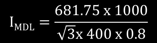
64 Example: For 2500 A busway: R t2 = 0.065*( (85-80)) mw/m H= 3*2500^2*0.068*0.00 Watts/m Assuming 2500 A load. H= Watts/m H= 3*230.5^2*0.068*0.00 Watts/m For specific load 230 A H= Watts/m H= 76.25*(32+80.) Watts for the entire busway Riser 8,548 Watts Formula for Current Load Based on Power Delivered P I 3 V cosf where, I = the load current in amperes P= the power delivered V= the system phase to phase voltage For Riser No. cosø = the power factor of the system P = kw cos Ø = 0.8 V = 400 Vac I = (68.75*000)/(sqrt(3)*400*ampere I =
65 Voltage Drop Calculations Assuming 400 Vac source voltage. The average phase to phase voltage drop for a given length at rated load current at a specfic load power factor is calculated using: VD avg L 3 I Ravg avg cos X sin where, L= the length of the run in meters I = the load current in amperes Ravg = the average 3Ø, Ø to N resistance in ohms per meter Xavg = the average 3Ø, Ø to N reactance in ohms per meter = the load power factor angle Example: For 2500 A busway, Riser : VDavg= (32+80.)*SQRT(3)* *(0.068*0.00* *0.00*SIN(ACOS(0.8))) %(Vdavg)= 9.96/400
66 Riser No. Rated Current of Proposed Busway 2500 ampere P = kw Device Type Length cos Ø = 0.8 CRJ2525G 05 ft 32.0 m V = 400 Vac CFJ2525G ft 80. m I = (68.75*000)/(sqrt(3)*400*0.8) Maximum Temperature Rise I = ampere Loading Bus Bar Housing Rated Full Load 5 34 H= Watts/m Actual Load H= 8,56 Watts for the entire busway Riser Distributed Load VDavg= 2.03 volts VDavg= 2.03*0.5 VDavg=.02 Distributed Load Concentrated Load VDavg= 5.09 volts Concentrated Load VDavg= VDavg= 6. volts %(Vdavg)=.53% for the entire busway Riser
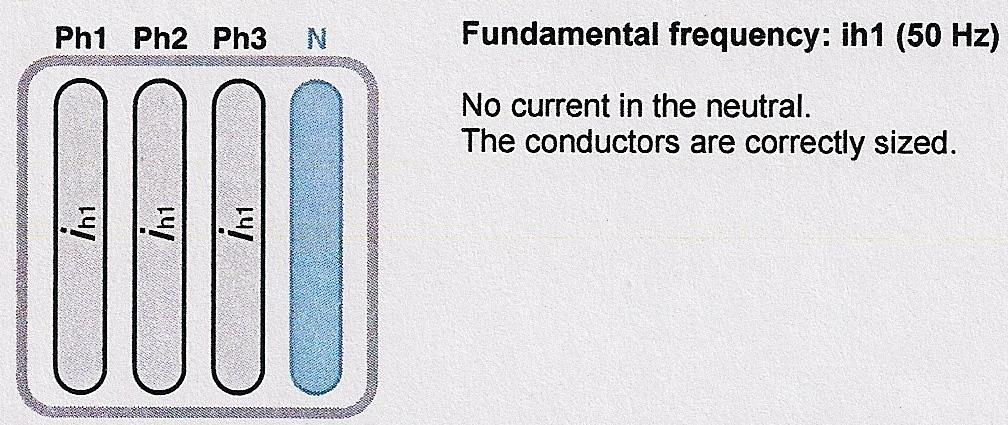
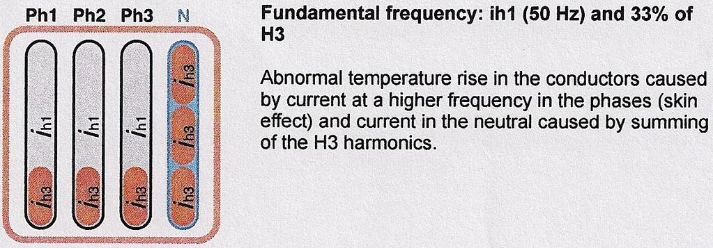
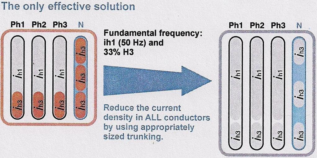
67 HARMONIC CURRENTS In installation with a distributed neutral, nonlinear loads may cause significant overloads in the neutral conductor due to the presence of THIRD-ORDER HARMONICS. By definition, the fundamental f is order (H) Third-order harmonics (H3) have a frequency if 50Hz (when f = 50 Hz.)
68 The presence of third-order harmonics depends on the applications involved. It is necessary to carry out an in-depth study on each non-linear load to determine the level of H3: ih3 (%) = 00 x i3 /i i3 = rms current of H3 I = rms current of the fundamental
69
70


 -")
71 Short-circuit current at LV side of Transformer Example: Transformer rating - 500kVA Voltage - / 0.4 kv % Impedance (Z) - 6 p.f
72 5. CHECK THE SHORT-CIRCUIT CURRENT WITHSTAND Check from the technical catalogue of busway manufacturer the short-circuit withstand of 2500A. Square D Busway short-circuit withstand. Icw (t = second) = 80kA Ipk = 98 ka Maximum short-circuit at the secondary of Transformer is 36kA. Therefore, 2500A busway short-circuit rating, 80kA is far higher. Selection is justified.
73 6. Protecting against busbar trunking overloads The busbar trunking is generally protected at its nominal current Inc or its allowable Iz if the ambient temperature coefficient k is applied. Circuit breaker protection: Adjust Ir of the circuit breaker such that: Iz = Ib x k Ir Inc
74 Circuit Breaker Protection Determination of design current, I MD considering 20% future load. P TCL = 26.25kW P MDL = P TCL x floor load diversity x Busway diversity SMDB Diversity per floor = 0.6 BUSWAY Diversity = 0.9 P MDL = x 0.6 x 0.9 x 0 floors P MDL = 68.75kW

75 Circuit Breaker Protection
76 Considering 20% future load Selection of protective device having nominal current rating or setting, In Adjust Ir of the circuit breaker such that: Iz = Ib x k Ir Inc In = 600A Use: 600A ACB
77 Circuit breaker protection allows busway to be used at full capacity because the standardized nominal current In of the circuit breaker is In Inc/k2 where is k2=.
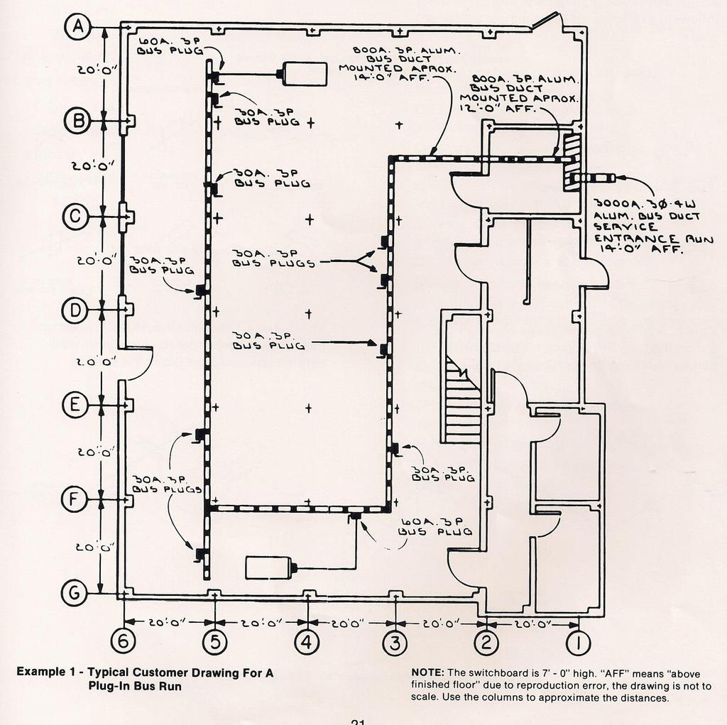
78 How To Do A Busway Take-off From Blueprints The following guidelines allow you to perform a busway take-off. First check the drawing list to confirm you have all the drawings for a complete take-off in the field. Generally, you will need the structural and mechanical drawings to confirm busway run has no obstruction along its route. 2. Carefully read the specifications and note any variations. If there are discrepancies between what is specified and what can be provided, the final quotation must list the exceptions. 3. Check the single line diagram and count the number of busway runs. If the voltage, ampacity, and run designations are stated, list these items. Ensure that the bill-of-material is complete.
79 4. If multiple busway runs are shown on each drawing and are continued on subsequent drawings, a complete run-by-run take-off is recommended. Check the scale on each drawing and detail, sometimes they vary. 5. To obtain the busway footage and the number of fittings (i.e. elbows, flanged ends, wall flanged, etc.): a. Measure the footage of the busway by scaling to centerline of the busway and fittings. b. If time permits, a simple sketch of each busway run is very helpful. Reference dimensions from known column lines to the busway and show them on your sketch, also note the busway elevation. c. List the number of fittings for each busway run. Be careful when crossing a building expansion joint to include the additional footage.
80 6. Once all the busway runs have been grouped according to ampere ratings, the busway footage pricing and busway fittings charges can be utilized to obtain the busway cost. 7. If busway tap boxes and overcurrent devices are not listed as per the take-off, review the drawings carefully and ensure to include these items to complete the list. If prices not available, send inquiry to manufacturer. Example- in the following page illustrates a simple take-off. As previously mentioned in 5(b), a sketch of the busway run being taken off is helpful.
81
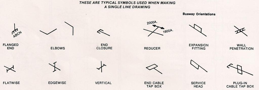
82 How To Make A Shorthand Drawing (Single line type) After the take-off has been made, a sketch of the run should be made. Single line drawings are the easiest way to illustrate a run. Remember that you should provide the factory with all pertinent information. The procedure is as follows:. Select the type of device you will need to draw (see next pages) 2. Check Typical single line sketch in the following examples for the run most similar to yours.
83

84 B - Typical Single Line Sketch of Plug-In Run
85 3. Draw your run. Be sure to label each run and show cross section where applicable 4. Show the phasing at each of the run 5. Show the location of each type of busway (i.e. location of weather proof and plug-in busway) 6. Indicate the quantity and, if necessary, location of plugs.
86 Busway Take-Off Checklist I. Ampere rating Type of Busway Busbar Material Number of Poles Thru 5000A - Plug-In: Std or High Shortcircuit bracing Feeder : Indoor or weather proof - Copper Aluminum - 3θ, 3W. or 3θ, 3W. With Ground 3θ, 4W. or 3θ, 3W. With Ground
87 II. Phasing shown on all switchboards, transformers and runs. Front or rear markings shown on switchboard and transformers. Location of busway runs entering switchboards and transformers. Complete dimensions supplied on low voltage section of transformer. Clear indication of busway mounting positions (edgewise, flatwise or vertical)
88 Location of walls and thicknesses. Quantity of wall flanged needed. Location of all fittings such as elbows, cable tap boxes, expansion joints, tees and reducers. Complete dimensions supplied on low voltage section of transformer.
89 III. Risers Only Designation of side that plugs are to be mounted on. Indication of type and quantity of plugs to be supplied per floor. Height of Plugs from floor. All closet dimensions supplied. Floor slab thickness.
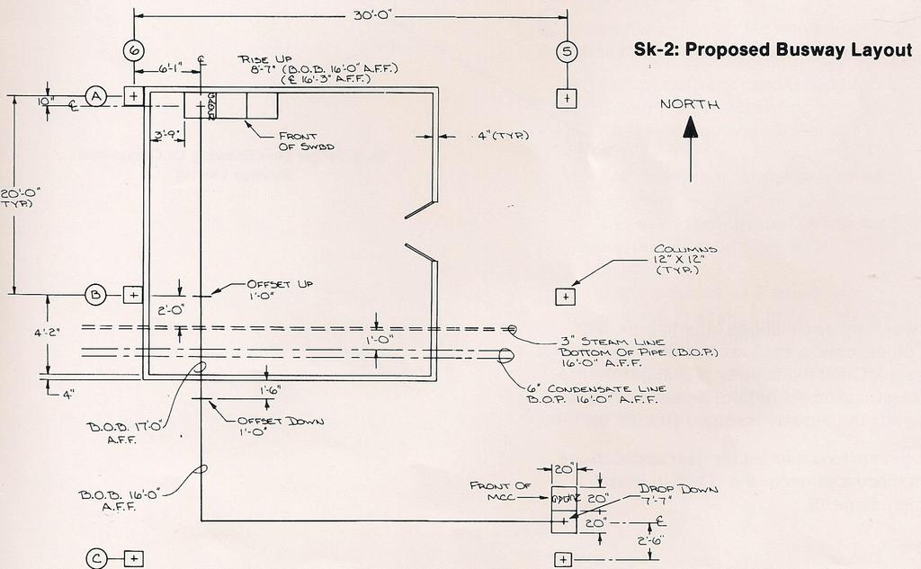
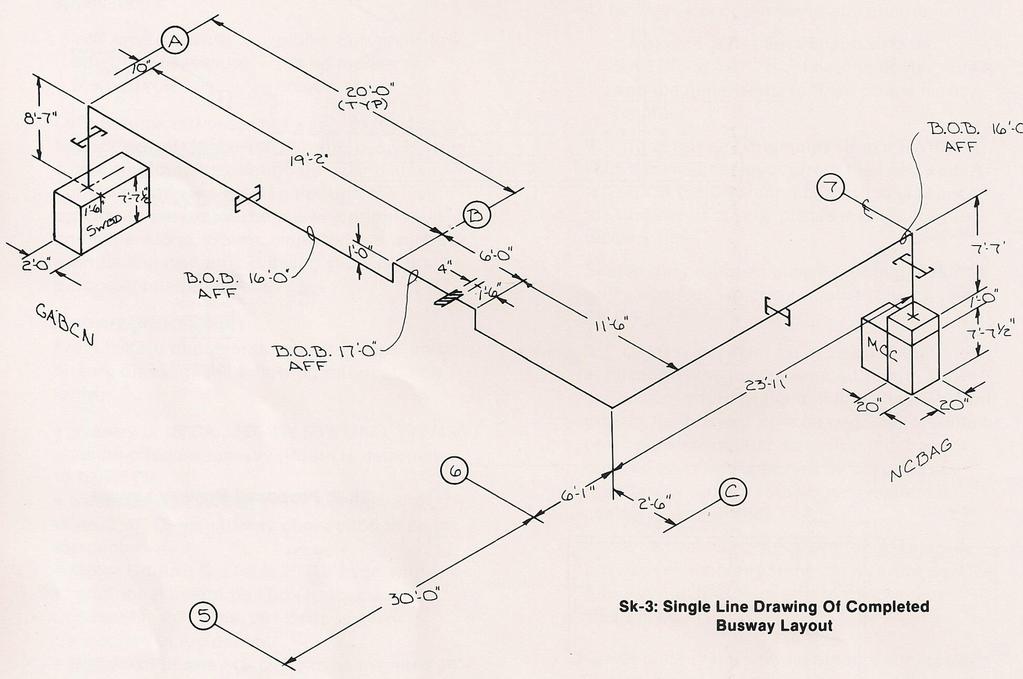
90 Helpful Hints To Layout And Measure A Busway Job Laying out and measuring a busway job does not require specialized tools or skills. The following list of tools should handle all applications: 30 meter tape measure Plumb bob/chalk line 7meter x 25mm tape measure Felt tip marker or crayon 6ft-wood rule. Let us assume our customer wants to feed a new MCC with busway from a new distribution switchboard. Using illustrations, we will go step-by-step through the layout process to determine the busway orientation and dimensions. When completed, we will have a single line isometric drawing showing the proposed busway layout.
91 Known Information Busway rating, system 3ph, 4wire full neutral with ground bar Switchboard details, i.e. height, depth and busway location on top of the cubicle. MCC details, i.e. height with additional pull box, depth and connection at top center. Bottom of busway (BOB) to be illustrated above finished floor unless obstructed. How To Begin. Determine the physical size of the busway housing. 2. Review the area where the busway could be installed (if not already specified). Note any special conditions such as building expansion joint, steel changes, plumbing, HVAC equipment, etc.
92 3. All dimensions should be measured from fixed points such as; columns and walls or other building structures. Try to leave 00mm clearance between busway and obstructions. 4. If busway originates from a SWBD, start dimensional layout from the fixed end. 5. Unless specified, for most industrial applications the busway should run above the bottom chord of the building steel. This will protect the busway from damage by fork-lifts or other equipment. Do not route the busway where it cannot be supported. Note that busway must be supported by drop rods. 6. When selecting the elevation for plug-in busway, remember that the over current device (plug-in units) require different mounting clearances.
 Sketch, Sk3 on the following page represents a typical dimensioned one-line drawing from which the customer could confirm the busway dimensions and the busway routing.")
93 From the sample busway layout (Sk-2) enough information is known to tabulate the amount of busway footage needed and the required fittings (i.e. flanged ends, elbows, etc.) Sketch, Sk3 on the following page represents a typical dimensioned one-line drawing from which the customer could confirm the busway dimensions and the busway routing.
94
95
96 Busway Take-Off Sheet Feeder Busway A Nr. Item Description Quantity. Flanged end 2 2. Elbow 90 C 7 3. Feeder Busway 945 or Horizontal Hanger 8 5. Vertical Hanger nil

97
Busbar Trunking Assembly
 Busbar Trunking Assembly 00A-600A : 000V Horizontal and Vertical applications Suitable for Reliable Power Distribution to: > industry > highrise buildings - transformer to switchboards - switchboards to
MV ELECTRICAL TRANSMISSION DESIGN AND CONSTRUCTION STANDARD. PART 1: GENERAL 1.01 Transformer
 PART 1: GENERAL 1.01 Transformer A. This section includes liquid filled, pad mounted distribution transformers with primary voltage of 12kV or 4.16kV (The University will determine primary voltage), with
1. All electrical switches and outlets used shall be equal to Hubbell heavy duty, specification grade or equivalent quality.
 PART 1: GENERAL 1.01 Wiring Devices A. This section of the standard includes design requirements for wiring connections, including receptacles and switches to equipment specified in other sections. 1.02
ZUCCHINI MS - LOW TO MEDIUM POWER BUSBAR
 ZUCCHINI MS - LOW TO MEDIUM POWER BUSBAR The flexibility of the Zucchini MS range during planning and installation makes it ideal for frequently changing requirements in small to medium sized commercial
Short-Circuit Current Calculations
 Basic Point-to-Point Calculation Procedure Step. Determine the transformer full load amps (F.L.A.) from either the nameplate, the following formulas or Table : Multiplier = 00 *% Z transformer Step 2.
SECTION LOW-VOLTAGE ELECT. DIST. DESIGN AND CONSTRUCTION STANDARDS _ February 2015 PART I: GENERAL
 PART I: GENERAL 1.01 Wiring Devices A. This section of the standard includes design requirements for wiring connections, including receptacles and switches to equipment specified in other sections. a.
Michigan State University Construction Standards SWITCHBOARDS, PANELBOARDS, AND CONTROL CENTERS PAGE
 PAGE 262400-1 SECTION 262400 PART 1 - GENERAL 1.1 RELATED DOCUMENTS A. Drawings and general provisions of the Contract, including General and Supplementary Conditions and Division 01 Specification Sections,
3Ø Short-Circuit Calculations
 3Ø Short-Circuit Calculations Why Short-Circuit Calculations Several sections of the National Electrical Code relate to proper overcurrent protection. Safe and reliable application of overcurrent protective
PREFACE ********************************************************** IT IS NOT INTENDED THAT THESE STANDARDS BE COPIED AND USED AS A SPECIFICATION!
 PREFACE This publication has been prepared as a guide for Architectural and Engineering (A&E) firms in the preparation of documents for the design and construction of new structures and the remodeling
Short Circuit Current Calculations
 Introduction Several sections of the National Electrical Code relate to proper overcurrent protection. Safe and reliable application of overcurrent protective devices based on these sections mandate that
IBAR (EMEA) LIMITED Castle Mills Aynam Road Kendal Cumbria LA9 7DE UK YEARS+ Established. t. +44 (0) e.
 LIMITED Castle Mills Aynam Road Kendal Cumbria LA9 7DE UK YEARS+ Established. t. +44 (0) e.") IBAR (EMEA) LIMITED Castle Mills Aynam Road Kendal Cumbria LA9 7DE UK 50 YEARS+ Established 966 t. +44 (0) 539 7206 e. sales@mardix.com www.resinbar.com A brand of IP68 Cast Resin Busbar System RESINBAR
IBAR (EMEA) LIMITED Castle Mills Aynam Road Kendal Cumbria LA9 7DE UK 50 YEARS+ Established 966 t. +44 (0) 539 7206 e. sales@mardix.com www.resinbar.com A brand of IP68 Cast Resin Busbar System RESINBAR
Chapter G Sizing and protection of conductors
 Chapter G Sizing and protection of conductors 1 2 3 4 5 6 7 8 Contents General 1.1 Methodology and definition G2 1.2 Overcurrent protection principles G4 1.3 Practical values for a protective scheme G4
50 YEARS+ A brand of the. IBAR (EMEA) LIMITED Castle Mills Aynam Road Kendal Cumbria LA9 7DE UK
 LIMITED Castle Mills Aynam Road Kendal Cumbria LA9 7DE UK") IBAR (EMEA) LIMITED Castle Mills Aynam Road Kendal Cumbria LA9 7DE UK 50 EARS+ Established 966 t. +44 (0) 539 706 e. sales@mardix.com www.resinbar.com A brand of the IP68 Cast Resin Busbar System RESINBAR
IBAR (EMEA) LIMITED Castle Mills Aynam Road Kendal Cumbria LA9 7DE UK 50 EARS+ Established 966 t. +44 (0) 539 706 e. sales@mardix.com www.resinbar.com A brand of the IP68 Cast Resin Busbar System RESINBAR
SECTION CABLE TRAYS
 SECTION 16139 CABLE TRAYS PART 1 - GENERAL 1.1 RELATED DOCUMENTS A. Drawings and general provisions of the Contract, including General and Supplementary Conditions and Division 1 Specification Sections,
UNITY/I TM. Installation Manual. UT3K, UT4K, UT5K and UT8K. Single-Phase Uninterruptible Power Systems
 UNITY/I TM UT3K, UT4K, UT5K and UT8K Single-Phase Uninterruptible Power Systems Installation Manual MLS-0351C-OL Copyright 1994-1997 Best Power. All rights reserved. å IMPORTANT SAFETY INSTRUCTIONS! SAVE
American Electrical Institute
 American Electrical Institute Oregon Electricians Continuing Education Grounding & Bonding (Article 250) 4 Hours American Electrical Institute PO Box 31131 Spokane, WA 99223 www.aeitraining.com Article
Article 250 Grounding & Bonding
 Article 250 Grounding & Bonding AMERICAN ELECTRICAL INSTITUTE N16 W23217 Stone Ridge Dr. Waukesha, WI 53188 855-780-5046 www.aeitraining.com DISCLAIMER NOTE: This course is APPROVED for continuing education
POWER DELEGATOR SERIES 7200A POWER DISTRIBUTION UNIT WITH POWER CONDITIONING GENERAL SPECIFICATIONS
 POWER DELEGATOR SERIES 7200A POWER DISTRIBUTION UNIT WITH POWER CONDITIONING GENERAL SPECIFICATIONS 1.0 SCOPE The following specification describes the features, design, and application of the Series 7200A
CONTINUING EDUC ATION
 3 CONTINUING EDUC ATION FOR WISCONSIN ELECTRICIANS 2017 NEC Article 250 2 Hours WISCONSIN CONTRACTORS INSTITUTE N16 W23217 Stone Ridge Drive Suite 290 Waukesha, WI 53188 262-409-4282 www.wcitraining.com
a) Determine the smallest, standard-sized circuit breaker that should be used to protect this branch circuit.
 Determine the smallest, standard-sized circuit breaker that should be used to protect this branch circuit.") ECET4520 Exam II Sample Exam Problems Instructions: This exam is closed book, except for the reference booklet provided by your instructor and one (8.5 x11 ) sheet of handwritten notes that may not contain
ECET4520 Exam II Sample Exam Problems Instructions: This exam is closed book, except for the reference booklet provided by your instructor and one (8.5 x11 ) sheet of handwritten notes that may not contain
Multi-conductor Lighting Busbar System A
 ISO 9001 101 ENVIRONMENTAL MANAGEMENT SYSTEMS QUALITY AND www.eae.com.tr Akcaburgaz Mahallesi, 119. Sokak, No:10 34510 EsenyurtIstanbulTurkey Tel: +90 (212) 866 20 00 Faks: +90 (212) 886 24 20 IEC 604392
GROUP MEGABARRE IMPACT. 800A 5000A Abu Dhabi Edition
 GROUP MEGABARRE IMPACT 800A 5000A Abu Dhabi Edition B U S B A R T R U K I G S Y S T E M GEERAL DATA TRUKIG ELEMETS COECTIO ELEMETS TAP-OFF UITS ACCESSORIES SUSPESIO UITS TECHICAL DATA ISTALLATIO ISTRUCTIOS
03/7/12 Issuance UTD Section Page 1 of 5 Electrical General
 SECTION 26 01 00 ELECTRICAL GENERAL PART 1: GENERAL 1.1 Electrical/Telecommunications Design 1.1.1 This section of the design and construction standard outlines general requirements for electrical and
PURCHASE SPECIFICATIONS 500KVA DRY TYPE TRANSFORMER FOR OIL RIG APPLICATIONS
 PURCHASE SPECIFICATIONS OF 500KVA DRY TYPE TRANSFORMER FOR OIL RIG APPLICATIONS SPECIFICATION NO. : OR12423 REVISION NO. : Rev 00 DATE : 01.03.2011 DISTRIBUTION : PI - 4 copies O/C - 1 copy PREPARED BY
GE Ventilated Dry-Type Transformers. Secondary Substation Transformers - 5 and 15kV Class
 GE Ventilated Dry-Type Transformers Secondary Substation Transformers - 5 and 15kV Class GE ventilated dry-type transformers are designed for indoor or outdoor applications in schools, hospitals, industrial
T-Line, current transformers
 Type HF, primary current up to 5000 amps, accuracy classes from 0.2S to 3, highest system voltage 720 volt T-Line, current transformers Catalogue 208 . Table for contents...2 2. Description Current transformers
Chapter 6. WIRING SYSTEMS Safe Electrical Design
 Chapter 6 WIRING SYSTEMS Safe Electrical Design Topic 6-3 CABLE SELECTION BASED ON CURRENT CARRYING CAPACITY REQUIREMENTS INSTALLATION CONDITIONS Current carrying capacity (CCC) is the maximum continuous
BUSBAR TRUNKING SYSTEMS 25A-63A AB-E SERIES. The smartest way of power distribution.
 BUSBAR TRUNKING SYSTEMS SERIES 25A-63A TABLE OF CONTENTS SERIES General Information 2-4 Project Information 5-6 Fittings Straight Lengths 7-8 Elbow Modules 8-9 Dilatation Module 9 Top Feed Module 10 End
Page Electric Utility Service Specifications
 T Y P I C A L U N D E R G R O U N D S E R V I C E R E Q U I R E M E N T S 200 Amps Maximum - UG-1 Sheet 1 of 3 87 T Y P I C A L U N D E R G R O U N D S E R V I C E R E Q U I R E M E N T S 200 Amps Maximum
Use RH covers when starting with a LH feed unit or when reaching the LH board. HIGH RATING
 Aluminium 1000A 1250A 1600A 2000A 2250A 2500A 3200A 4000A 4500A R 95503111 95503131 95503131 95503141 95513111 95513131 95513131 95513141 95513151 L 95503211 95503231 95503231 95503241 95513211 95513231
Electrical Wiring: Commercial, Seventh Canadian Edition
 Electrical Wiring Commercial Canadian 7th Edition Mullin SOLUTIONS MANUAL Full download at: https://testbankreal.com/download/electrical-wiring-commercialcanadian-7th-edition-mullin-solutions-manual/ Unit
2. Electrical rooms shall be centrally located and stacked so that feeder conduits and bus duct are run as straight and short as possible.
 PART 1: GENERAL 1.01 Electrical/Telecommunications Design A. This section of the design and construction standard outlines general requirements for electrical and telecommunications designs to be performed
SECTION CABLE TRAYS FOR COMMUNICATIONS SYSTEMS
 SECTION 270536 - CABLE TRAYS FOR COMMUNICATIONS SYSTEMS PART 1 - GENERAL 1.1 RELATED DOCUMENTS A. Drawings and general provisions of the Contract, including General and Supplementary Conditions and Division
MECKLENBURG COUNTY. Land Use and Environmental Service Agency Code Enforcement 2/9/11 ELECTRICAL CONSISTENCY MEETING. Code Consistency Questions
 MECKLENBURG COUNTY Land Use and Environmental Service Agency Code Enforcement 2/9/11 ELECTRICAL CONSISTENCY MEETING Code Consistency Questions 1. I have a 500 KVA generator, with no overcurrent protection
Busbar and Modular Wiring Systems
 Chapter 11 Busbar and Modular Wiring Systems 11.1 BUSBAR SYSTEM The wide range of busbar system is available and can be used for single or three-phase distribution to many types of applications ranging
GLS A GLS 15
 GLS 25-40-63A GLS 15 GLS Graziadio Busbar Graziadio have been making busbar in Italy since 1959. Originally founded by Antonio Graziadio. The company continued to expand its sales and product ranges within
SOLAR PV MICROINVERTER/ACM STANDARD PLAN - COMPREHENSIVE Microinverter and ACM Systems for One- and Two- Family Dwellings
 SOLAR MICROINVERTER/M STANDARD PLAN - COMPREHENSIVE Microinverter and M Systems for One- and Two- Family Dwellings SCOPE: Use this plan ONLY for systems using utility-interactive Microinverters or Modules
Wisconsin Contractors Institute Continuing Education
 IMPORTANT NOTE: You should have received an email from us with a link and password to take your final exam online. Please check your email for this link. Be sure to check your spam folder as well. If you
CONSULTANT PROCEDURES & DESIGN GUIDELINES Liquid-Filled Utility Transformers UNIVERSITY OF MISSOURI
 GENERAL: The scope of this document is to provide instruction for the installation and testing of Medium Voltage, 3 Phase, Pad Mounted Transformers installed at the University of Missouri. Preferred transformers
VI 3 - i TABLE OF CONTENTS
 VI 3 - i TABLE OF CONTENTS 3 PROJECT SPECIFIC DATA... 1 3.1 DEFINITIONS... 1 3.1.1 Design Data, High and Medium Voltage... 1 3.1.2 Design Data, Low Voltage Equipment... 2 3.1.3 Phase Relationship... 3
Mobile distribution Canalis KXA (50 to 160 A) with mobile connections
 with mobile connections") What you should know p Environmental conditions of installation : - minimum and maximum ambient temperatures - external influences, dust, corrosion, etc. p Run layout. p Characteristics of the load(s)
What you should know p Environmental conditions of installation : - minimum and maximum ambient temperatures - external influences, dust, corrosion, etc. p Run layout. p Characteristics of the load(s)
2/15/2015. Current will always try to return to its source. In order for there to be current, there must be a complete circuit
 Current will always try to return to its source In order for there to be current, there must be a complete circuit Current will take as many paths or circuits available to it to return to the source The
TABLE OF CONTENT
 Page : 1 of 34 Project Engineering Standard www.klmtechgroup.com KLM Technology #03-12 Block Aronia, Jalan Sri Perkasa 2 Taman Tampoi Utama 81200 Johor Bahru Malaysia TABLE OF CONTENT SCOPE 3 REFERENCES
50 YEARS+ HX Range Catalogue. IBAR (EMEA) LIMITED Castle Mills Aynam Road Kendal Cumbria LA9 7DE UK
 LIMITED Castle Mills Aynam Road Kendal Cumbria LA9 7DE UK") H Range Catalogue IBAR (EMEA) LIMITED Castle Mills Aynam Road Kendal Cumbria LA9 7DE UK EARS+ Established 1966 t. +44 (0) 1539 720161 e. sales@mardix.com www.mardix.com/ibar Contents Mardix are the UK
H Range Catalogue IBAR (EMEA) LIMITED Castle Mills Aynam Road Kendal Cumbria LA9 7DE UK EARS+ Established 1966 t. +44 (0) 1539 720161 e. sales@mardix.com www.mardix.com/ibar Contents Mardix are the UK
SB 50 Connectors - up to 120 amps
 Connectors - up to 120 amps Based off the design pioneered by Anderson in 1953, APP s two pole SB connectors set the standard for DC power distribution and battery connections. connectors feature a one
7. INSPECTION AND TEST PROCEDURES
 7.1 Switchgear and Switchboard Assemblies A. Visual and Mechanical Inspection 1. Compare equipment nameplate data with drawings and specifications. 2. Inspect physical and mechanical condition. 3. Inspect
K Factor Power Transformers
 Ashley-Edison AsiaElectricTransformers (UK) K Factor Power Transformers DTKF series Low Voltage Dry Type K Factor Power Transformers AET-DTKF-2004-01: Page 1 Asia Electric Transformers, Entrepreneur Business
Medium power busbar trunking
 Canalis KS (100 to 800 A) For high density distribution in industrial and commercial buildings Presentation 4 1 2 5 1 Run components 7 ratings : 100, 160, 250, 400, 500, 630 and 800 A 4 live conductors.
DOCUMENT ADDENDUM NO. 4. Issued to all Bidders: Date: October 14, Contract Name: Electrical Installation. Contract Number: C8410
 DOCUMENT 009104 - ADDENDUM NO. 4 Issued to all Bidders: Date: October 14, 2015 Contract Name: Electrical Installation Contract Number: C8410 This addendum forms a part of the Bid described above. The original
Premium 30 Energy Efficient, Low Voltage Transformers General Purpose, Harmonic Mitigating, and K-Rated
 Premium 30 Energy Efficient, Low Voltage Transformers General Purpose, Harmonic Mitigating, and K-Rated Catalog 7400CT1001 2010 Class 7400 CONTENTS Description.............................................
HPS Universal BUCK-BOOST TRANSFORMERS
 BUCK-BOOST TRANSFORMERS Single and Three Phase Potted Buck-Boost Transformers Buck-Boost Applications & Standard Specification... 80 Selecting Buck-Boost Transformers... 81 Single Phase Selection Tables...
Three-phase short-circuit current (Isc) calculation at any point within a LV installation using impedance method
 calculation at any point within a LV installation using impedance method") Three-phase short-circuit current (Isc) calculation at any point within a LV installation using impedance method Calculation of Isc by the impedance method In a 3-phase installation Isc at any point is
Three-phase short-circuit current (Isc) calculation at any point within a LV installation using impedance method Calculation of Isc by the impedance method In a 3-phase installation Isc at any point is
UBC Technical Guidelines Section Edition Medium-Voltage Transformers Page 1 of 5
 Page 1 of 5 1.0 GENERAL 1.1 Coordination Requirements.1 UBC Energy & Water Services.2 UBC Building Operations 1.2 Description.1 UBC requirements for Substation Transformers. 2.0 MATERIAL AND DESIGN REQUIREMENTS
INSTRUCTION MANUAL. Type SWF. Sine Wave Filters 690 Volts, 50Hz
 POWER QUALITY INSTRUCTION MANUAL Type SWF Sine Wave Filters 690 Volts, 50Hz Page 2 of 24 Contents 1. Introduction & SAFETY 2. Theory of operation 3. Typical results of the Sine Wave Filters 4. Transportation,
Chapter 1. Applied Grounding and Bonding. Applied Grounding and Bonding 9/18/2011. Introduction. Introduction. Paul Dobrowsky Member NEC Panel 5
 Applied Grounding and Bonding Paul Dobrowsky Member NEC Panel 5 1 Introduction This presentation is a representative sample from the following Chapters of Applied Grounding and Bonding. Chapter 1, Introduction
Description & Applications Questions & Answers Selection Charts Single Phase Selection Charts Three Phase...
 SECTION BUCK-BOOST TRANSFORMERS A simple and economical way to correct offstandard voltages... from 95 to 500 volts; single and three phase, in sizes up to 60 kva. Simplified buck-boost rating charts make
UNIVERSITY OF MISSOURI Liquid-Filled Utility Transformers 2016 Q1
 GENERAL: The scope of this document is to provide instruction for the installation and testing of Medium Voltage, 3 Phase, Pad Mounted Transformers installed at the University of Missouri. Preferred transformers
Low Voltage Products. Third Harmonic Filter THF and THF star System components for assembly and retrofitting. Catalogue THFS2GB 03_05 1SCC330004C0201
 Low Voltage Products Third Harmonic Filter and star System components for assembly and retrofitting Catalogue SGB _ SCCC System components for assembly and retrofitting star, installation in the transformer
DATA SHEET FOR LIGHTING TRANSFORMER APPD. BY VDV PROJECT NO
 PART - A : SPECIFIC REQUIREMENTS THIS DATA SHEET IS APPLICABLE FOR IN BOILER A CLIMATIC CONDITIONS PACKAGE 1 DESIGN AMBIENT TEMPERATURE 45 C 2 ALTITUDE ( ABOVE MSL ) 6.71 MTRS. 3 RELATIVE HUMIDITY 74 %
 PROJECT: SUPPLY & INSTALL ELECTRICAL SWITCHBOARD AT SENGKURONG EXCHANGE PHASE 1, JLN TUTONG, BSB. SCOPE OF WORK The scope of work under Electrical Services shall include but not limited to the supply,
INTRODUCTION NUHAS OMAN QUALITY & RELIABILITY.
 INTRODUCTION Nuhas Oman LLC, an integral part of The Al Bahja Group of Companies, is a Quality producer of: HV, MV and LV Cables Enamelled Copper Wires Oxygen Free Continuous Cast Copper Wire Rods Drawn
Neutral Earthing. For permanent or temporary neutral earthing in HV systems
 Neutral Earthing Resistors RESISTORS For permanent or temporary neutral earthing in HV systems For continuous or temporary low-resistance neutral grounding in medium voltage systems Neutral point connection
ELECTRICAL GENERAL DESIGN AND CONSTRUCTION STANDARD PART 1: GENERAL Electrical/Telecommunications Design
 PART 1: GENERAL 1.01 Electrical/Telecommunications Design A. This section of the design and construction standard outlines general requirements for electrical and telecommunications designs to be performed
Power Distribution Blocks with Short-Circuit Current Ratings
 Power Distribution Blocks with Short-Circuit Current Ratings General Information: The requirements of the 005 National Electric Code (NEC) and UL508A now require many electrical panels to carry a Short
4. Special Systems Design: including Fire Alarm and Security. C. Electrical and Telecommunications Ductbanks: Refer to Section 16118
 PART 1: GENERAL This section of the design standard outlines general requirements for electrical and telecommunications designs to be performed for the University of Texas at Austin. This standard is intended
INSTALLATION, OPERATION AND MAINTENANCE GUIDE
 INSTALLATION, OPERATION AND MAINTENANCE GUIDE FOR INDOOR/OUTDOOR SINGLE PHASE ENCAPSULATED TRANSFORMERS Indoor/Outdoor Encapsulated Transformers The pictures used in this guide are only a representation
Steps for Selecting the Proper Transformer
 SECTION I Page 4 Steps for Selecting the Proper Transformer SINGLE PASE LOADS 1. Determine electrical load A. Voltage required by load. B. Amperes or KVA capacity required by load. C. Frequency in z (cycles
I -limiter The world s fastest switching device
 I S -limiter 2 I S -limiter The world s fastest switching device Reduces substation cost Solves short-circuit problems in new substations and substation extensions Optimum solution for interconnection
LBPLUS DATA. he new busbar unking system for LIGHTING MANAGEMENT. Range
 LBPLUS DATA The he new busbar trunking unking system for LIGHTING MANAGEMENT, the new busbar conceived for distribution and lighting in the service sector, which integrates a BUS that can be used for Lighting
Current / residual current and voltage transformers. Current / residual current and voltage transformers
 Current / residual current and voltage transformers Current / residual current and voltage transformers 1 Overview Current transformer overview DIN rail current transformer with fuse Current transformer...
3-phase short-circuit current (Isc) at any point within a LV installation
 at any point within a LV installation") 3-phase short-circuit current (Isc) at any point within a LV installation In a 3-phase installation Isc at any point is given by: where U 20 = phase-to-phase voltage of the open circuited secondary windings
3-phase short-circuit current (Isc) at any point within a LV installation In a 3-phase installation Isc at any point is given by: where U 20 = phase-to-phase voltage of the open circuited secondary windings
B. Manufacturers: Square-D, G.E. or Westinghosue.
 SECTION 16470 - PANELBOARDS PART 1 - GENERAL 1.01 RELATED DOCUMENTS A. General: Drawings and general provisions of the Contract, including General and Supplementary Conditions and Division 1 Specification
ELECTRICIAN S THEORY EXAMINATION 15 November 2014 QUESTION AND ANSWER BOOKLET
 Candidate Code No. ET51 For Board Use Only Result Date Int Result Date Int ELECTRICIAN S THEORY EXAMINATION 15 November 2014 QUESTION AND ANSWER BOOKLET INSTRUCTIONS READ CAREFULLY Time Allowed: Three
Electrical IP Red Seal Practice Exam
 Electrical IP Red Seal Practice Exam PRACTICE EXAM-3 1. What size 2 pole breaker must you use on a 3HP, 115V single phase motor? A. 40A B. 50A C. 80A. D. 100A. 2. An electrical equipment approved for use
DMRC ELECTRICAL STANDARDS & DESIGN WING (DESDW)
") DELHI METRO RAIL CORPORATION LIMITED DMRC ELECTRICAL STANDARDS & DESIGN WING (DESDW) SPECIFICATION NO. DMES- 0005/ DMRC-E-TR-TRANSF-05 SPECIFICATIONS FOR THREE PHASE 33 kv/415 V AUXILIARY Issued on: Date
DELHI METRO RAIL CORPORATION LIMITED DMRC ELECTRICAL STANDARDS & DESIGN WING (DESDW) SPECIFICATION NO. DMES- 0005/ DMRC-E-TR-TRANSF-05 SPECIFICATIONS FOR THREE PHASE 33 kv/415 V AUXILIARY Issued on: Date
S INGLE CIRCU I T 120V. LABELING: cul listed. GES Track Components. Flex Connector GES 23 GES 17. Dead Ends GES 41. (use with any connector)
") S INGLE CIRCU I T 120V G E S 1 CIR 120V Power supply for ElectraLED track lighting fixtures Architectural grade, extruded aluminum housing Milled grounding bar provides continuous ground contact Continuously
S INGLE CIRCU I T 120V G E S 1 CIR 120V Power supply for ElectraLED track lighting fixtures Architectural grade, extruded aluminum housing Milled grounding bar provides continuous ground contact Continuously
Article 225: Outside Branch Circuits And Feeders
 Part C: Code Book Questions Article 225: Outside Branch Circuits And Feeders 1.! Open (individual) aerial overhead conductors shall be insulated or covered when within! feet of a building.! (a) 10! (c)
COMMON WORK RESULTS FOR INTEGRATED AUTOMATION DESIGN AND CONSTRUCTION STANDARD
 PART 1: GENERAL 1.01 Purpose: A. This standard is intended to provide useful information to the Professional Service Provider (PSP) to establish a basis of design. The responsibility of the engineer is
5/2 Introduction. Unequipped Distribution Boards 5/4 Modular distribution boards 5/5 Add-on parts
 ALPHA AS Modular Distribution Boards /2 Introduction Unequipped Distribution Boards /4 Modular distribution boards / Add-on parts Assembly Kits for Unequipped Distribution Boards /6 8GK4 assembly kits
Dry-Type Transformers
 Dry-Type Transformers 600 Volt Class Bulletin 7700-99 ISO 9002 Registered 1 Federal Pacific Federal Pacific History During 1987, the Electro-Mechanical Corporation acquired the dry-type transformer division
DESIGN CONSIDERATION OF ELECTRICAL DISTRIBUTION AND LIGHTNING PROTECTION SYSTEMS FOR HIGH-RISE BUILDING
 DESIGN CONSIDERATION OF ELECTRICAL DISTRIBUTION AND LIGHTNING PROTECTION SYSTEMS FOR HIGH-RISE BUILDING 1 LAI LAI WIN, 2 KHIN THUZAR SOE 1 Electrical Power Engineering Department, Mandalay Technological
MECKLENBURG COUNTY. Land Use and Environmental Service Agency Code Enforcement 9/8/10 ELECTRICAL CONSISTENCY MEETING. Code Consistency Questions
 conduit? 9/8/10 ELECTRICAL CONSISTENCY MEETING Code Consistency Questions 1. Can branch circuits of different services be installed in the same Yes, see 300.3(C)(1) for conductors of different systems
ELECTRICAL NETWORKS SPECIFICATION TECHNICAL SPECIFICATION FOR A 230V/110V AND 400V/110V TRANSFORMER
 Approval Amendment Record Approval Date Version Description 03/05/2017 1 Initial issue PRINTOUT MAY NOT BE UP-TO-DATE; REFER TO METRO INTRANET FOR THE LATEST VERSION Page 1 of 13 Table of Contents 1. Purpose...
Hi5 s Expert Guide to Specify afix Lecture Hall Tables
 Hi5 s Expert Guide to Specify afix Lecture Hall Tables Table Tops Page 2 Table Edges Page 3 Bases Page 4 6 Modesty Panels Page 7 Power Page 8 Wire Management Page 9 ADA Tables Page 10 Finish Choices Page
Brown University Revised 2/1/2006 Facilities Design & Construction Requirements SECTION 16461C - DRY TYPE TRANSFORMERS
 SECTION 16461C - DRY TYPE TRANSFORMERS PART 1 - GENERAL 1.1 This section includes design and performance requirements for dry-type transformers rated for use on secondary distribution systems rated 600
RCP IP68 RESIN BUSBAR TRUNKING GLOBAL SPECIALIST IN ELECTRICAL AND DIGITAL BUILDING INFRASTRUCTURE
 RCP IP68 RESIN BUSBAR TRUNKING GLOBAL SPECIALIST IN ELECTRICAL AND DIGITAL BUILDING INFRASTRUCTURE IP68 RCP RESIN BUSBAR TRUNKING New resin busbar RCP ranging from 6 A to A and IP68 degree of protection,
Amveco Toroidal Solutions. Acme Electric s class leading toroidal magnetics is the perfect solution for the most challenging applications.
 Amveco Toroidal Solutions Acme Electric s class leading toroidal magnetics is the perfect solution for the most challenging applications. AMVECO TOROIDAL SOLUTIONS Acme Electric s Amveco brand specializes
500 kva Dry-type Isolation Transformer V-Delta to 208Y/120V 3PH - NEMA 1/Indoor
 500 kva Dry-type Isolation Transformer - 13200V-Delta to 208Y/120V 3PH - NEMA 1/Indoor Part #: MT-DOE16-3P-13200D-500KVA-208Y.120-N1 Page: 1 The MT-DOE16-3P-13200D-500KVA-208Y.120-N1 Dry-type Isolation
Variable Transformers Product Design & Engineering Data
 Variable Transformers Product Design & Engineering Data Product Design & Engineering Data Type 1010B Cutaway General Information STACO ENERGY PRODUCTS CO. is a leading manufacturer of variable transformers,
SPECIFICATION FOR STEP UP TRANSFORMER 0.415/11Kv and (630KVA & 1000KVA)
") SPECIFICATION FOR STEP UP TRANSFORMER 0.415/11Kv and (630KVA & 1000KVA) 0.415/33kV DESIGN AND CONSTRUCTION General 1. The transformer shall be three phase, oil immersed type, air cooled, core type, outdoor
SPECIFICATION FOR STEP UP TRANSFORMER 0.415/11Kv and (630KVA & 1000KVA) 0.415/33kV DESIGN AND CONSTRUCTION General 1. The transformer shall be three phase, oil immersed type, air cooled, core type, outdoor
GE Monogram. Installation. Instructions. 36" Vent Hood. Model ZV750. Call anywhere in the US and Canada -
 at :: rangehoods. com GE Monogram Instructions Model ZV750 GE Monogram at:: rangehoods. com is a division of CAUTION WARNING Before you begin Read these instructions completely and carefully. IMPORTANT:
Digital Lighting Systems, Inc.
 PD408-AN0-277 ANALOG 0-0 V 0-0V analog control 4 Channel x 2250 W Dimmer & Switch Packs 220/240/277 Volts operation PD408-AN0-277 4 circuit Analog -0V 4 x 8 A. Dimmer pack Serial Number Digital Lighting
Device Interconnection
 Device Interconnection An important, if less than glamorous, aspect of audio signal handling is the connection of one device to another. Of course, a primary concern is the matching of signal levels and
SECTION PANELBOARDS
 PART 1 - GENERAL 1.1 DESCRIPTION SECTION 26 24 16 PANELBOARDS SPEC WRITER NOTE: Delete between // --- // if not applicable to project. Also, delete any other item or paragraph not applicable in the section
SINGLE PHASE BUCK & BOOST TRANSFORMERS INSTRUCTION MANUAL
 SINGLE PHASE INSTRUCTION MANUAL DIAGRAM D This manual applies to all single-phase buck & boost transformers sold by Larson Electronics. Please refer to the connection diagram on pages 4-6 for properly
ECET 211 Electric Machines & Controls Lecture 3-1 (Part 1 of 2) Motor Transformers and Distribution Systems
 Motor Transformers and Distribution Systems") ECET 211 Electric Machines & Controls Lecture 3-1 (Part 1 of 2) Motor Transformers and Distribution Systems Text Book: Electric Motors and Control Systems, by Frank D. Petruzella, published by McGraw Hill,
ECET 211 Electric Machines & Controls Lecture 3-1 (Part 1 of 2) Motor Transformers and Distribution Systems Text Book: Electric Motors and Control Systems, by Frank D. Petruzella, published by McGraw Hill,
Quality Control Checklist - Design Drawings
 Quality Control Checklist - Design Drawings Date Company Name Address Telephone Fax Email Job Number 1) Drawing Set a) Drawing one is site/location/incoming power i) Should contain location map if not
Liquid-Filled Transformers
 Liquid-Filled Transformers Custom Transformers at Standard Prices NIAGARA TRANSFORMER CORP. Induction Furnace Transformer Cycloconverter Rectifier Duty Transformer Arc Furnace Transformer Full Range of
Electrical Theory. Power Principles and Phase Angle. PJM State & Member Training Dept. PJM /22/2018
 Electrical Theory Power Principles and Phase Angle PJM State & Member Training Dept. PJM 2018 Objectives At the end of this presentation the learner will be able to: Identify the characteristics of Sine
ELECTRICIAN S THEORY EXAMINATION 19 November 2016 QUESTION AND ANSWER BOOKLET
 Candidate Code No. ET 60 For Board Use Only Result Date Int Result Date Int ELECTRICIAN S THEORY EXAMINATION 19 November 2016 QUESTION AND ANSWER BOOKLET INSTRUCTIONS READ CAREFULLY Time Allowed: Three