Mitigating Murphy s Law While Test. Frédéric Dollinger
|
|
|
- Christopher Clark
- 5 years ago
- Views:
Transcription


1 Mitigating Murphy s Law While Test Frédéric Dollinger

2 Curriculum Vitae Frédéric Dollinger HAEFELY HIPOTRONICS factory Basel Switzerland Area Sales & Marketing Manager Dipl. Ing. / M.Sc. Mechatronic Language: English, German, French fdollinger@haefely.com 2

3 About Us - Production - Sales - Service Brewster, NY US - Production - Sales - Service Basel, Switzerland Employees: 200+ Production Areas: USA, Switzerland Sales Centers: USA, Switzerland, China Service Points: USA, Switzerland, China, India Representatives: Worldwide - Service Sao Paulo, Brazil - Service Kochi, India - Sales - Service Beijing, China
4 History 4


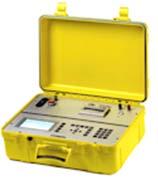
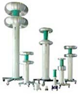
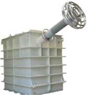
5 Our Product Range DC Impulse Transformer Test System Frequency Converter Measurement Instruments Loss Meas. PD - C/tanδ - TTR Winding Resistance Meas. - FRA Recovery Voltage AC Customized Cable Test system EMC Measurement fwfwcwcsdceddd 5
6 Agenda Introduction to Murphy s Law Murphy s Law Case Study Cases Study Analysis 6
7 Introduction to Murphy s Law 7

8 Anything that can go wrong will go wrong 8

9 Case study Origin: this study shares what has been seen and experienced onsite from us Target: provide important insight and illuminate previously hidden issues Systematic approach: each case is studied with the mention of the fault, the cause of the fault, the consequence and the solution. 9
10 Murphy s Law Case Study 10
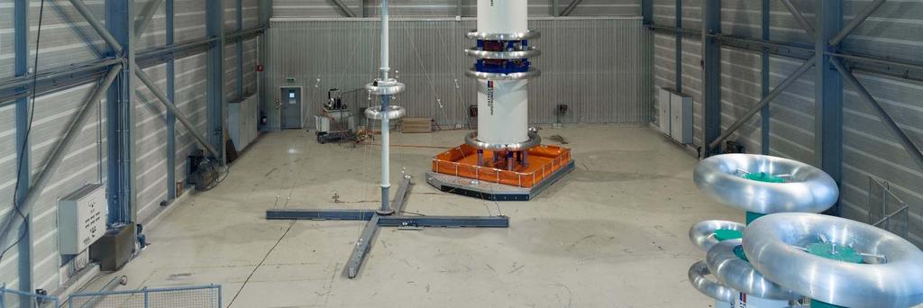
11 Case Study: HV 1 Situation Induced Voltage Test Problem C-Bank explosion Factory on fire Difficulty: Low Failure: System Cause C-Bank was in the test circuit during the induced voltage test Consequence 72 kv / 200 Hz applied on a 20 kv 60 Hz C-Bank Can be avoided: Yes Dangerous: Yes 11
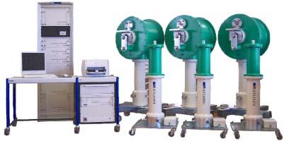
12 Case Study: HV 1 Classic test system for induced voltage test, no load and load loss, heat run Typical example for heat run: 20 kv / 60 Hz Typical example for induced voltage test: 72 kv / 200 Hz Power Grid Matching Item V Variable U PWM Contr Sin Filter Frequency Converter, 540 kva Item 10.1 LV Filter Step up HV Filter Item 10.2 Item 11 Item 12 CT PT DUT TMS Item 13 Variable U PWM Contr Sin Filter Frequency Converter, 540 kva Item 10.1 LV Filter Item 10.2 Compens. Item 14 Variable U PWM Contr Sin Filter Frequency Converter, 540 kva Item 10.1 LV Filter Item Container Item 10 12


13 Case Study: HV 1 C-Bank fire is most of the time a dramatic situation, as the bank is installed inside the factory! 13

14 Case Study: HV 1 Solution: overall test system intelligence should avoid dangerous situation!! 14
15 Case Study: HV 2 Situation Onsite DC Hipot on submarine cable Problem Ultra high voltage DC generator breaks down Difficulty: Low Failure: human Cause Customer replaced the damping resistance, which was wrongly designed Consequence After cable break down, the flash went back to the DC generator, the damping resistance could not stop the high current and the DC generator breaks down Can be avoided: Yes Dangerous: Yes 15

16 Case Study: HV 2 Onsite test on a 35 km submarine cable The onsite test cabin was too small Customer decides the replace the damping resistor with a shorter damping resistor. (same resistance value!) DC hipot at 380 kv Breakdown of the cable Flash back with huge current to the damping resistor, the flash goes over the resistor and destroys the generator 16
17 Case Study: HV 3 Situation Applied voltage test Problem Flash Difficulty: Low Failure: Human Cause Wrong divider ratio setting Consequence Flash Can be avoided: Yes Dangerous: Yes 17
18 Case Study: HV 3 18
19 Case Study: Imp 1 Situation Impulse test on power transformer Problem Overlapping oscillation Difficulty: Low Failure: System Cause Impulse generator too far from test object, no-air cushion to move it closer to the test object Consequence High loop inductance L loop Can be avoided: Yes Dangerous: No 19
20 Case Study: Imp 1 Relative overshoot magnitude ß shall not exceed 5% (IEC ed3.0) 20
21 Case Study: Imp 1 Usual test setup for LI test The higher L loop, the higher overlapping oscillation C s : resulting impulse capacitance R s : Front (series) resistor R p : Tail (parallel) resistor L loop : inductance of test circuit Impulse Generator Transformer L b : inductance of transformer C b : capacitance of transformer 21

22 Case Study: Imp 1 Solution: have an impulse generator with air cushion L loop 22

23 Case Study: Imp 1 Solution: have an impulse generator with air cushion L loop 23
24 Case Study: Imp 2 Situation LI test on power transformer, on the low voltage side Problem Tail time t 2 too short, out of the IEC ed 3.0 specification Difficulty: Low Failure: System Cause Very low transformer winding inductance Consequence Short Tail time t 2 Does not fulfill IEC ed 3.0 Can be avoided: Yes Dangerous: No 24


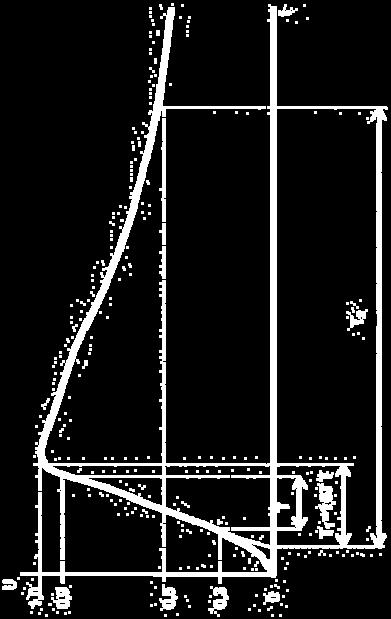
25 Case Study: Imp 2 IEC ed
26 Case Study: Imp 2 Rule: The lower the inductance Lcc, the lower the tail time T 2. This is the case for the lower the voltage class and the higher the rated power of the transformer 26
27 Case Study: Imp 2 C b : 13nF L b : 1.1mH 27
28 Case Study: Imp 2 Even with more capacitance, T 2 would not rise Glaninger: T 2 is 270 % higher as with the 1s2p config. Glaninger is the smart solution 28


29 Case Study: Imp 2 Solution: Glaninger Circuit 29
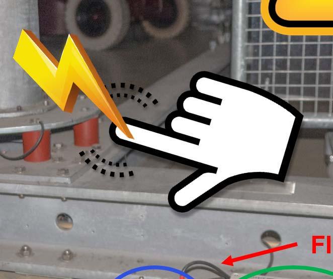
30 Case Study: Imp 3 Situation Impulse voltage test Problem: During the impulse generator configuration: low / medium energy discharge to the operator Difficulty: Low Failure: System Cause Capacitor was not grounded after use; the capacitor is charging alone back due to internal polarization phenome Consequence Risk of low / medium discharge to the operator, risk to fall down from the sky lift Can be avoided: Yes Dangerous: Yes 30


31 Case Study: Imp 3 Caution without grounding: Risk of discharge! the capacitor is charging alones back due to internal polarization phenome Cap.: 1-3 uf / 100 KV 31


32 Case Study: Imp 3 Solution: Auto. grounding Cap.: 1-3 uf / 100 KV 32
33 Case Study: PD 1 Situation PD measurement Problem Flash Difficulty: High Failure: Human Cause Floating coupling capacitor Consequence Flash between divider and ground Can be avoided: Yes - no Dangerous: Yes 33

34 Case Study: PD 1 34
35 Case Study: PD 1 Usual test setup: AC source + coupling capacitor + meas. Imp. + PD detector Test engineer has 2 PD detectors / measuring impedances (end user request) He changes the measuring impedance and forgets to ground it Coupling capacitor is floating Flash occurs while rising voltage After power off, the coupling cap. remains charged: dangerous situation 35


36 Case Study: PD 1 Floating ground Meas. Imp. 1 Meas. Imp. 2 36
37 Case Study: PD 2 Situation PD Measurement on transformer Problem: Wrong PD values/measurement Difficulty: Low Failure: Human Cause Operator did not calibrate the measuring circuit for each new test object Consequence Each test object has different capacitance, which makes impossible to know the PD amplitude Can be avoided: Yes Dangerous: No 37
38 Case Study: PD 2 Calibration procedure: inject an know q 0 impulse and adjust the ratio at the detector. 38

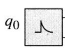
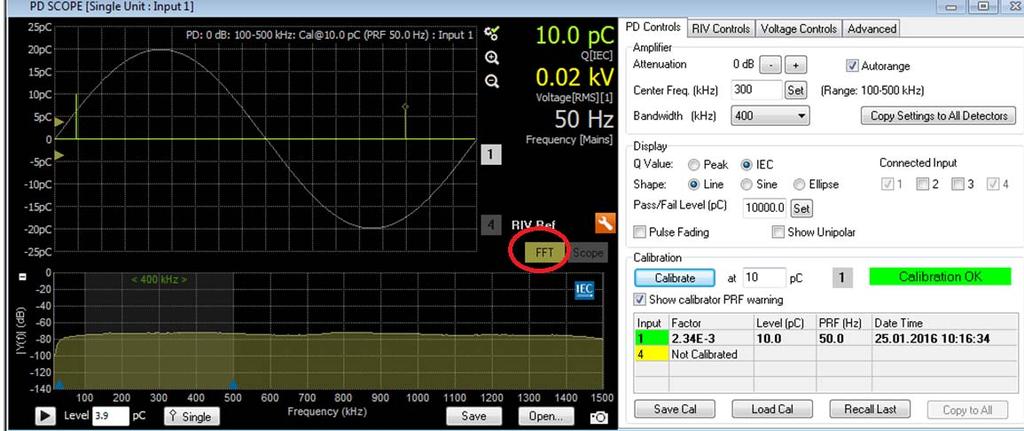
39 Case Study: PD 2 Calibration procedure: 39
40 Case Study: PD 3 Situation PD Measurement on transformer Problem: High PD values/measurement Difficulty: Medium Failure: System Cause Fixed dead time leading to ambiguous recognition of partial discharge pulse Consequence Partial discharge undershoot is interpreted as pulse Can be avoided: Yes Dangerous: No 40
41 Case Study: PD 3 Dynamic dead time VS fixed dead time Dynamic dead time: 1 pulse Fixed dead time: up to 3 pulses 41

42 Case Study: PD 3 Typical situation: This is one partial discharge pulse Dead time: time to blind out the undershoot 42
 distinct recognition without ambiguity, thanks to dynamic dead time (automatic) 43")
43 Case Study: PD 3 Dynamic dead time VS fixed dead time: Pulse polarity: a) ambiguous recognition due to fixed dead time, wrongly set b) distinct recognition without ambiguity, thanks to dynamic dead time (automatic) 43

44 Case Study: PD 3 Dynamic dead time VS fixed dead time: Challenge with fixed dead time settings: each PD source might need another setting! Inner PD source Internal cavity/void in insulating material Air bubbles in oil Non-uniformities in SF6 insulation system Outer PD source: Corona Surface (gliding/creeping discharges) 44
45 Case Study: PD 4 Situation PD Measurement on transformer Problem: Wrong PD measurement Difficulty: Low Failure: System / human Cause Measurement out of the IEC standard measurement band (higher frequency range) Consequence On the higher frequency range, the PD activity is not visibible anymore Can be avoided: Yes Dangerous: No 45
 30 khz f1 100 khz, f2 1000 khz 100 khz f 900 khz PD pulse loses high frequency")
46 Case Study: PD 4 Wide-band PD instruments (chapter in IEC 60270:2015) 30 khz f1 100 khz, f khz 100 khz f 900 khz PD pulse loses high frequency content while travelling thru transformer 46
47 Case Study: WR 1 Situation Onsite winding resistance measurement on power transformer Problem At transformer reconnection, the substation switches off Difficulty: Low Failure: System Cause The winding resistance is a DC measurement. The core remains magnetized after measurement Consequence -Magnetized core -DC offset -Inrush current -Substation switches off Can be avoided: Yes Dangerous: Yes 47
48 Case Study: Loss 1 Situation Load Loss measurement on a power transformer Problem Higher loss readings Difficulty: Low Failure: System Cause Wrong accuracy class of the Wattmeter Consequence Small power factor leads to high loss error readings Can be avoided: Yes Dangerous: No 48
49 Case Study: Loss 1 Phase angle error of 1min in the voltage or current will result in approx. 3 % error in loss meas. for a power factor of 0.01 Load loss at low power factor are very sensitive to phase angle Phase angle error of 1min IEEE Std C [4.3] 49
50 Case Study: Loss 1 During meas: the transformer behaves inductive Power factor tends to fall with rising values of rated power Typical example: kva transformer: load loss 1 %, short circuit impedance 6 % of ref. impedance power factor of the series impedance: MVA transformer: load loss 0.4 %, short circuit impedance 15 % of ref. impedance power factor of the series impedance: IEC:1997 [9.6] 50


51 Case Study: Loss 1 IEC :
52 Case Study: Loss 2 Situation No Load Loss measurement on a distribution transformer Problem Higher loss readings Difficulty: Low Failure: System Cause Deviation on the excitation voltage Consequence Higher loss readings Can be avoided: Yes Dangerous: No 52
 During no load loss measuring, the transformer is in the saturation working")
53 Case Study: Loss 2 1% deviation on the applied voltage would increase 1% to 3 % the losses Solution: accurate voltage output (step less adjustment, feedback loop with the measurement) During no load loss measuring, the transformer is in the saturation working area
54 Case Study: Loss 3 Situation No Load Loss measurement on a distribution transformer Problem Higher loss readings Difficulty: Low Failure: System Cause High THD on the voltage waveshape Consequence Higher loss readings Can be avoided: Yes Dangerous: No 54
![Case Study: Loss 3 T.H.D.: Total Harmonic Distortion IEC 60076-1:2011 [11.1.1]: Voltage: THD < 5% T.H.D. cause: T.H.D. on the voltage waveshape comes mainly from the short circuit impedance of the test system T.](/docs-images/90/103062173/images/55-2.jpg "H.D. problem: Peaked waves with higher r.m.s. can lead to higher losses Z test system U Z test system U Z test object Z test object 55")
55 Case Study: Loss 3 T.H.D.: Total Harmonic Distortion IEC :2011 [11.1.1]: Voltage: THD < 5% T.H.D. cause: T.H.D. on the voltage waveshape comes mainly from the short circuit impedance of the test system T.H.D. problem: Peaked waves with higher r.m.s. can lead to higher losses Z test system U Z test system U Z test object Z test object 55

56 Case Study: Loss 3 Example on a kva, 33 kv / 400 V transformer Without THD Control With THD Control 3% Difference


57 Case Study: Loss 3 Without THD Control Example on a kva, 33 kv / 400 V transformer With THD Control OCT 2015 TLM 2015 Dubai 57


58 Case Study: Loss 3 Without THD Control Example on a kva, 33 kv / 400 V transformer With THD Control
59 Case Study: Loss 4 Situation No Load Loss measurement on a distribution transformer Problem Higher loss readings Difficulty: Low Failure: System Cause Unsymmetric voltage waveshape Consequence Higher loss readings Can be avoided: Yes Dangerous: No 59

60 Case Study: Loss 4 Example on a kva, 33 kv / 400 V transformer Without Symmetry Control With Symmetry Control 3% Difference
61 Case Study: Loss 5 Situation No Load Loss measurement on a transformer Problem Higher loss readings Difficulty: Low Failure: Human Cause Magnetized core Consequence Higher loss readings Can be avoided: Yes Dangerous: No 61
62 Case Study: Loss 5 Prehistory of magnetization Remanence in the core after saturation during winding resistance meas. or by unidirectional long-duration impulses, may leave a trace in the no load loss meas. A systematic demagnetization of the core before no load meas. is recommended to establish representative results IEEE Std C [3.2.2] IEC:1997 [9.6] 62

63 Case Study: Loss 5 ABB Book: ABB_2010_Testing of Power Transformers and Shunt Reactors, Routine Type and Special Tests, page 72 the No Load loss: 63
64 Case Study: FRA Situation FRA Measurement on power transformer Problem: Measurement differs from reference Difficulty: Medium - High Failure: human Cause Multiple: Oil, magnetization, connection, temperature Consequence FRA shows deviation Can be avoided: Yes Dangerous: No 64

65 Case Study: FRA Power Transformer filled with different oil onsite as at the factory Ref: IEC ed

66 Case Study: FRA Power transformer measured onsite before filling the oil Ref: IEC ed

67 Case Study: FRA Power transformer measured after winding resistance measurement without demagnetization Ref: IEC ed

68 Case Study: FRA Power transformer measured at different temperature Ref: IEC ed

69 Case Study: FRA Power transformer measured with bad connection Ref: IEC ed
70 Case Study: FRA Ref: IEC ed
71 Case Study: PF 1 Situation Power factor measurement on transformer Problem: Wrong measurement Difficulty: Low Failure: human Cause Dirty bushing Consequence Leakage current increases the power factor Can be avoided: Yes Dangerous: No 71
72 Case Study: PF 1 72
73 Case Study: PF 2 Situation Power factor measurement on transformer Problem: Wrong measurement Difficulty: Low Failure: human Cause High humidity during the measurement (morning, after rain, snow, etc ) Consequence Leakage current increases the power factor Can be avoided: Yes Dangerous: No 73
74 Case Study: PF 2 Rules of dump 65 % rel. humidity: 10 x higher leakage current 80 % rel. humidity: 100 x higher leakage current 95% rel. humidity: 1000 x higher leakage current Depending on the test object, leakage current can have a large impact. We do not recommend to measure above 65 % - 80 % rel. humidity 74
75 Case Study: PF 3 Situation Power factor measurement on transformer Problem: Wrong measurement Difficulty: Low Failure: human Cause Wrong temperature correction Consequence Temperature correction depends on the test object. A wrong setup gives high deviation Can be avoided: Yes Dangerous: No 75

76 Case Study: PF 3 Temperature correction example 76
77 Case Study: PF 4 Situation Power factor measurement on transformer Problem: Impossible to perform correct measurement Difficulty: Low Failure: System Cause GST setup is needed, but the power supply is not compatible Consequence If the power supply does not have a separate ground output, is it impossible to perform a GST measurement. Can be avoided: Yes Dangerous: No 77


78 Case Study: PF 4 UST and GST test setup: High Voltage power supply is connected to earth Test object is connected to earth Ungrounded specimen test UST Grounded specimen test GST 78


79 Cases Study Analysis 79

80 Anything that can go wrong will go wrong, But all situations could have been avoided!!!!!!!! 80


81 Technology level If a system is the cause of a fault, upgrading the system would be the solution Better technology will avoid system failure! 81

82 Safety Half of the dangerous situations are caused by the system technology. Upgrading the system would fix the problem. Think safety first and if requested upgrade the system! 82

83 Knowledge Half of the problems are linked to operator knowledge. Read the user manual first and get trained! 83


84 84
Automatic Transformer Winding Analyser
 2293 Automatic Transformer Winding Analyser The 2293 is an automatic winding analyser, optimized for three phase power and distribution transformer measurements. It uniquely combines winding resistance
TD-106. HAEFELY HIPOTRONICS Technical Document. Partial Discharge Pulse Shape Analysis to Discriminate Near and Far End Failures for Cable Location
 HAEFELY HIPOTRONICS Technical Document Partial Discharge Pulse Shape Analysis to Discriminate Near and Far End Failures for Cable Location P. Treyer, P. Mraz, U. Hammer Haefely Hipotronics, Tettex Instruments
TMS 580. Transformer Loss Measuring System FEATURES BENEFITS APPLICATIONS
 TMS 580 Transformer Loss Measuring System The measurement of the losses in power transformers is an indispensable quality-verification process. Due to the fact that normally the transformer user puts a
GENERATOR TESTING APPLICATION GUIDE. reliable. precision.
 GENERATOR TESTING APPLICATION GUIDE www.haefely-hipotronics.com reliable. precision. 2 GENERATOR TESTING CONTENTS Product Line Overview 3 AC Hipot Testing 4 Partial Discharge Measurement 5 DC Hipot Testing
KIT 4.0 HIGH VOLTAGE CONSTRUCTION KIT. reliable. precision. HIGH V O L T A G E T E S T S OLUTION S
 KIT 4.0 HIGH VOLTAGE CONSTRUCTION KIT reliable. precision. HIGH V O L T A G E T E S T S OLUTION S 2 General Description GENERAL DESCRIPTION APPLICATION The KIT 4.0 is a high voltage system made of easily
TD-100. HAEFELY HIPOTRONICS Technical Document
 HAEFELY HIPOTRONICS Technical Document Breaking the limit of power capacitor resonance frequency with help of PD pulse spectrum to check and setup PD measurement P. Treyer, P. Mraz, U. Hammer, S. Gonzalez
Variation in SFRA plot due to design and external parameter
 Chapter 6 Variation in SFRA plot due to design and external parameter 6.1 Introduction As the experience grows with Sweep Frequency Response Analysis in world, it is useful to discuss the measurements
EFFECT OF INTEGRATION ERROR ON PARTIAL DISCHARGE MEASUREMENTS ON CAST RESIN TRANSFORMERS. C. Ceretta, R. Gobbo, G. Pesavento
 Sept. 22-24, 28, Florence, Italy EFFECT OF INTEGRATION ERROR ON PARTIAL DISCHARGE MEASUREMENTS ON CAST RESIN TRANSFORMERS C. Ceretta, R. Gobbo, G. Pesavento Dept. of Electrical Engineering University of
Understanding and Extracting Valuable Information from Basic and Advanced Power Transformer Testing Techniques
 Understanding and Extracting Valuable Information from Basic and Advanced Power Transformer Testing Techniques Charles Sweetser, Services Manager, PRIM Engineering, Waltham, Mass. Topics of Discussion
HV AC TESTING OF SUPER-LONG CABLES
 HV AC TESTING OF SUPER-LONG CABLES Stefan SCHIERIG, (Germany), schierig@highvolt.de Peter COORS, (Germany), coors@highvolt.de Wolfgang HAUSCHILD, IEC, CIGRE, (Germany), hauschild@highvolt.de ABSTRACT The
شركة الوقت للكهرباء والمقاوالت ذ.م.م.
 CONTRACTING COMPANY W.L.L. is a leading corporate in the United Arab Emirates offering quality services in the field of High Voltage Electrical work 400, 132 & 33 kv and Medium Voltage Power Distribution
MEDIUM & HIGH VOLTAGE
 MEDIUM & HIGH VOLTAGE TESTING EQUIPMENT VOLTAGE WITHSTAND SGM Series Resonant Systems The SGM series are used for generating high AC voltages at a fixed frequency (mainly 50 or 60 Hz) by means of an excited
PRODUCT PORTFOLIO TEST AND MEASURING SYSTEMS
 PRODUCT PORTFOLIO TEST AND MEASURING SYSTEMS n Quality made in Germany n Standardized and customized solutions n Turn key projects, all from one hand 0.1-1/1 Product Portfolio Test and Measuring Systems
10. DISTURBANCE VOLTAGE WITHSTAND CAPABILITY
 9. INTRODUCTION Control Cabling The protection and control equipment in power plants and substations is influenced by various of environmental conditions. One of the most significant environmental factor
Understanding the Value of Electrical Testing for Power Transformers. Charles Sweetser, OMICRON electronics Corp. USA
 Understanding the Value of Electrical Testing for Power Transformers Charles Sweetser, OMICRON electronics Corp. USA Understanding the Value of Electrical Testing for Power Transformers Charles Sweetser,
High Votage Module AC/DC/Impulse Test System
 TSGADI Series High Votage Module AC/DC/Impulse Test System A digital control and measuring system is used to be control the difference output AC/DC/Impulse and related protection device such as over voltage
Power Frequency Withstand Voltage On-site testing of 400 kv GIS
 Power Frequency Withstand Voltage On-site testing of 400 kv GIS D. Anaraki Ardakani, A. Omidkhoda, M. Solati High Voltage Engineering Center ACECR Tehran, Iran Da_ardakani@yahoo.com Paper Reference Number:
Three-Phase Transformer Test Systems
 Three-Phase Transformer Test Systems PHENIX TECHNOLOGIES R Testing Applications Models Available Perform tests on utility distribution and power transformers in accordance with IEC 60076 and ANSI / IEEE
IEC/CIGRE UHV Symposium Beijing Paper 4.2. Challenges on the measuring and testing techniques for UHV AC and DC equipment
 IEC/CIGRE UHV Symposium Beijing 2007-07-23 Paper 4.2 Challenges on the measuring and testing techniques for UHV AC and DC equipment E. GOCKENBACH 1 ; W. HAUSCHILD 2, S. SCHIERIG 2, M. MUHR 3, W. LICK 3,
CDAX 605 High Precision Capacitance & Dissipation Factor Test Set
 CDAX 605 High Precision Capacitance & Dissipation Factor Test Set 1 Tan delta and capacitance measurements Hi V A Lo Ground C HL Measure with AC test signal, use Ohms law to calculate: Dissipation factor
700 Series AC Dielectric Test Sets
 700 Series AC Dielectric Test Sets AC Test Systems HAEFELY HIPOTRONICS standard line of AC Dielectric Test Systems is designed to perform high voltage AC tests on electrical apparatus in accordance with
Evaluation and Limitations of Corona Discharge Measurements An Application Point of View
 Evaluation and Limitations of Corona Discharge Measurements An Application Point of View P. Mraz, P. Treyer, U. Hammer Haefely Hipotronics, Tettex Instruments Division 2016 International Conference on
The University of New South Wales. School of Electrical Engineering and Telecommunications. High Voltage Systems ELEC9712. Appendix Partial Discharge
 The University of New South Wales School of Electrical Engineering and Telecommunications High Voltage Systems ELEC9712 Appendix Partial Discharge Content Introduction Quantities measured Test circuits
Discipline Electrical Testing Issue Date Certificate Number T-2837 Valid Until Last Amended on - Page 1 of 6 LOCATION 1
 Post: Last Amended on - Page 1 of 6 LOCATION 1 I. TRANSFORMERS AND REACTORS 1. 500 MVA, 765 kv 500 MVA, 400 kv Ratio & Polarity Check Magnetic Balance & Magnetizing Current Measurement at Low Voltage Vector
Chapter 7 Conclusion 7.1 General
 Chapter 7 7.1 General The mechanical integrity of a transformer winding is challenged by several mechanisms. Many dielectric failures in transformers are direct results of reduced mechanical strength due
process has few stages and is highly repeatable. Excellent mechanic properties and electro-magnetic compatibility. Planar design gives the height lowe
 PARTIAL DISCHARGE IN PLANAR TRANSFORMER Ing. Anar MAMMADOV, Doctoral Degreee Programme (1) Dept. of Microelectronics, FEEC, BUT E-mail: xmamed00@stud.feec.vutbr.cz Supervised by Dr. Jaroslav Boušek ABSTRACT
MIDAS 2881 / 2881G. Mobile Insulation Diagnosis & Analysing System
 MIDAS 2881 / 2881G Mobile Insulation Diagnosis & Analysing System Measurement of insulation losses is performed during periodic maintenance and inspection of high voltage equipment like power transformers,
Practical aspects of PD localization for long length Power Cables
 Practical aspects of PD localization for long length Power Cables M. Wild, S. Tenbohlen University of Stuttgart Stuttgart, Germany manuel.wild@ieh.uni-stuttgart.de E. Gulski, R. Jongen onsite hv technology
Transformer Factory Testing
 Transformer Factory Testing John J. Foschia Test Engineer John.Foschia@spx.com September 2018 Reasons for Testing Compliance with user specifications Assessment of quality and reliability Verification
Reprint E Two Years of Experience with a Mobile Resonant Test System for Testing of Installed Medium- and High Voltage Power Cables
 Two Years of Experience with a Mobile Resonant System for ing of Installed Medium- and High Voltage Power Cables P. Schikarski M. Gamlin J. Rickmann P. Peeters P. v.d. Nieuwendijk R. Koning Reprint ISH
HIGH VOLTAGE ENGINEERING(FEEE6402) LECTURER-24
 LECTURER-24") LECTURER-24 GENERATION OF HIGH ALTERNATING VOLTAGES When test voltage requirements are less than about 300kV, a single transformer can be used for test purposes. The impedance of the transformer should
LECTURER-24 GENERATION OF HIGH ALTERNATING VOLTAGES When test voltage requirements are less than about 300kV, a single transformer can be used for test purposes. The impedance of the transformer should
Understanding the Value of Electrical Testing for Power Transformers. Charles Sweetser - OMICRON
 Understanding the Value of Electrical Testing for Power Transformers Charles Sweetser - OMICRON Transformers Diagnostic Testing - OVERALL DGA Oil Screen Power Factor / Capacitance Exciting Current Transformer
Partial Discharge Measurement and Monitoring on High Voltage XLPE Cables
 21, rue d Artois, F-75008 PARIS AUCKLAND 2013 http : //www.cigre.org Partial Discharge Measurement and Monitoring on High Voltage XLPE Cables Michael Krüger, Rene Hummel, Stefan Böhler, OMICRON Austria
Power Engineering II. High Voltage Testing
 High Voltage Testing HV Test Laboratories Voltage levels of transmission systems increase with the rise of transmitted power. Long-distance transmissions are often arranged by HVDC systems. However, a
Error vs. Uncertainty Historical Perspective
 1 Error vs. Uncertainty Historical Perspective Jim McBride Chairman PSIM Committee Vice-Chairman HVTT Subcommittee IEEE PES SPDC Fall 2017 Clearwater, FL Discussions on Uncertainty PSIM - HVTT Subcommittee
Type Test of a 145 kv Termination Type TS 145-II
 Test Report No 2009-125/2 Type Test of a 145 kv Termination Type TS 145-II Client: 3 M Deutschland GmbH Carl-Schurz-Str.1 41453 Neuss Reporter: Dr.-Ing. R. Badent Dr.-Ing. B. Hoferer This report includes
High Voltage Diagnostics Sarl 4, Rue de Lac CH 1897 Le Bouveret Switzerland
 High Voltage Diagnostics Sarl 4, Rue de Lac CH 1897 Le Bouveret Switzerland Company HV Diagnostics Sarl is a Swiss based company in the field of high voltage test equipment for cable testing and diagnosis.
Technical Questionnaire 9.101/6 Transformer Test System. Personal Data. Application. Test of. Delivery scope
 Date: Page: 1 / 10 Personal Data Name: Company / institution: Phone: E-mail: Fax: Application Quotation number: (will be filled in by HIGHVOLT) Test field, stationary research institute mobile on-site
Matz Ohlen Director Transformer Test Systems. Megger Sweden
 Matz Ohlen Director Transformer Test Systems Megger Sweden Frequency response analysis of power transformers Measuring and analyzing data as function of frequency, variable frequency diagnostics Impedance
FGJTCFWP"KPUVKVWVG"QH"VGEJPQNQI[" FGRCTVOGPV"QH"GNGEVTKECN"GPIKPGGTKPI" VGG"246"JKIJ"XQNVCIG"GPIKPGGTKPI
 FGJTFWP"KPUKWG"QH"GEJPQNQI[" FGRTOGP"QH"GNGETKEN"GPIKPGGTKPI" GG"46"JKIJ"XQNIG"GPIKPGGTKPI Resonant Transformers: The fig. (b) shows the equivalent circuit of a high voltage testing transformer (shown
Diagnostic testing of cast resin transformers
 Paper of the Month Diagnostic testing of cast resin transformers Author Michael Krüger, OMICRON, Austria michael.krueger@omiconenergy.com Christoph Engelen, OMICRON, Austria christoph.engelen@omicronenergy.com
ISSN: [IDSTM-18] Impact Factor: 5.164
![ISSN: [IDSTM-18] Impact Factor: 5.164](/thumbs/91/106796217.jpg "ISSN: [IDSTM-18] Impact Factor: 5.164") IJESRT INTERNATIONAL JOURNAL OF ENGINEERING SCIENCES & RESEARCH TECHNOLOGY A REVIEW OF ROUTINE TESTING ON DISTRIBUTION TRANSFORMER Sukhbir Singh 1, Parul Jangra 2, Anoop Bhagat 3, Vipin Saini 4 1 Assistant
IJESRT INTERNATIONAL JOURNAL OF ENGINEERING SCIENCES & RESEARCH TECHNOLOGY A REVIEW OF ROUTINE TESTING ON DISTRIBUTION TRANSFORMER Sukhbir Singh 1, Parul Jangra 2, Anoop Bhagat 3, Vipin Saini 4 1 Assistant
Mobile Power Transformer Test Systm
 TMPTTS Series Mobile Power Transformer Test Systm MPTTS Series Mobile Power Transformer Test System is design to test and diagnose in both single phase and three phase power transformer up to 500MVA. The
Importance of Transformer Demagnetization
 Available online at www.sciencedirect.com ScienceDirect Procedia Engineering 00 (2017) 000 000 www.elsevier.com/locate/procedia 4th International Colloquium "Transformer Research and Asset Management Importance
DEPARTMENT OF ELECTRICAL AND ELECTRONICS ENGINEERING QUESTION BANK SUBJECT CODE & NAME : EE 1402 HIGH VOLTAGE ENGINEERING UNIT I
 DEPARTMENT OF ELECTRICAL AND ELECTRONICS ENGINEERING QUESTION BANK SUBJECT CODE & NAME : EE 1402 HIGH VOLTAGE ENGINEERING YEAR / SEM : IV / VII UNIT I OVER VOLTAGES IN ELECTRICAL POWER SYSTEMS 1. What
CT Analyzer. Revolution in current transformer testing and calibration
 CT Analyzer Revolution in current transformer testing and calibration Revolutionary way of CT testing Current transformers are used for relaying and metering purposes in electrical power systems. They
FRAX Series Sweep Frequency Response Analyzers
 FRAX Series Highest dynamic range and accuracy in the industry Fulfills international standards for SFRA measurements Advanced analysis and decision support built into the software. FRAX 150 with built
AC Dielectric Test Sets
 AC Dielectric Test Sets AC Test Systems Hipotronics standard line of AC Test Systems are designed to perform high voltage AC tests on electrical apparatus in accordance with IEC60, IEEE 4 and IEC 270 and
TRAINING OVERVIEW EDUCATION IS POWER. HIGH V O L T A G E T E S T S OLUTION S. reliable. precision.
 TRAINING OVERVIEW EDUCATION IS POWER www.hipotronics.com/training reliable. precision. HIGH V O L T A G E T E S T S OLUTION S 2 EDUCATION IS POWER EDUCATION IS POWER LEARN WHAT WE HAVE TO OFFER Through
Electric Stresses on Surge Arrester Insulation under Standard and
 Chapter 5 Electric Stresses on Surge Arrester Insulation under Standard and Non-standard Impulse Voltages 5.1 Introduction Metal oxide surge arresters are used to protect medium and high voltage systems
Power Measurements and Basic Electrical Diagnostic Tests
 Power Measurements and Basic Electrical Diagnostic Tests Instrument Basics Burden VA Sources V and I Meters V and I KVL and KCL Kelvin Connection KVL and KCL Kelvin Connection 4-Wire Technique Exclude
IDAX 300 Insulation Diagnostic Analyzer. Dielectric Frequency Response Also known as: Frequency Domain Spectroscopy
 IDAX 300 Insulation Diagnostic Analyzer Dielectric Frequency Response Also known as: Frequency Domain Spectroscopy 1 Frequency Domain Spectroscopy Hi V A Lo Ground C HL Measure at several frequencies Use
STRAY FLUX AND ITS INFLUENCE ON PROTECTION RELAYS
 1 STRAY FLUX AND ITS INFLUENCE ON PROTECTION RELAYS Z. GAJIĆ S. HOLST D. BONMANN D. BAARS ABB AB, SA Products ABB AB, SA Products ABB AG, Transformers ELEQ bv Sweden Sweden Germany Netherlands zoran.gajic@se.abb.com
POWER TRANSFORMER SPECIFICATION, DESIGN, QUALITY CONTROL AND TESTING 18 MARCH 2009
 POWER TRANSFORMER SPECIFICATION, DESIGN, QUALITY CONTROL AND TESTING 18 MARCH 2009 Nkosinathi Buthelezi Senior Consultant: Power Transformers and Reactors Presentation Content Standardization of Power
Vallabh Vidyanagar, Anand, INDIA
 IOSR Journal of Electrical and Electronics Engineering (IOSR-JEEE) e-issn: 2278-1676,p-ISSN: 2320-3331, Volume 9, Issue 1 Ver. V (Feb. 2014), PP 01-06 Interpretation of Sweep Frequency Response Analysis
IMPORTANCE OF ACCURATE MEASUREMENTS DURING THE LIFE CYCLE OF UTILITIES
 IMPORTANCE OF ACCURATE MEASUREMENTS DURING THE LIFE CYCLE OF UTILITIES Thomas Steiner HIGHVOLT Prüftechnik Dresden GmbH Lifecycle of utilities time schedule utilities Tests during life cycle of utilities
SGM series. AC Resonant Test System. Applications & Advantages
 SGM series AC Resonant Test System insulated switchgear (GIS), but also large rotating machines, instrument and power transformers (for applied voltage tests). Resonant test systems enable not only HVAC
Alternative Testing Techniques for Current Transformers. Dinesh Chhajer, PE Technical Support Group MEGGER
 Alternative Testing Techniques for Current Transformers Dinesh Chhajer, PE Technical Support Group MEGGER Agenda Current Transformer Definition and Fundamentals Current Transformer Applications o Metering
A Comparison Between MIL-STD and Commercial EMC Requirements Part 2. By Vincent W. Greb President, EMC Integrity, Inc.
 A Comparison Between MIL-STD and Commercial EMC Requirements Part 2 By Vincent W. Greb President, EMC Integrity, Inc. OVERVIEW Compare and contrast military (i.e., MIL-STD) and commercial EMC immunity
CHAPTER 2. v-t CHARACTERISTICS FOR STANDARD IMPULSE VOLTAGES
 23 CHAPTER 2 v-t CHARACTERISTICS FOR STANDARD IMPULSE VOLTAGES 2.1 INTRODUCTION For reliable design of power system, proper insulation coordination among the power system equipment is necessary. Insulation
Measurement and Analysis for Switchmode Power Design
 Measurement and Analysis for Switchmode Power Design Switched Mode Power Supply Measurements AC Input Power measurements Safe operating area Harmonics and compliance Efficiency Switching Transistor Losses
TTR2796. Fully Automated Three Phase 250V Transformer Turns Ratio Meter FEATURES AND BENEFITS APPLICATIONS
 TTR2796 Fully Automated Three Phase 250V Transformer Turns Ratio Meter A close collaboration with major transformer manufacturers has lead to the new HAEFELY HIPOTRONICS 2796 Transformer Turns Ratio Meter.
GIS Instrument Transformers: EMC Conformity Tests for a Reliable Operation in an Upgraded Substation
 GIS Instrument Transformers: EMC Conformity Tests for a Reliable Operation in an Upgraded Substation W. Buesch 1) G. Palmieri M.Miesch J. Marmonier O. Chuniaud ALSTOM LTD 1) ALSTOM LTD High Voltage Equipment
Insulation Test System
 Component Tests Insulation Test System Brief Overview of Phenomena............... 2 Applicable Standards................... 3 Test System Overview.................. 3 Generator Specifications.................
2. Current interruption transients
 1 2. Current interruption transients For circuit breakers or other switching facilities, transient voltages just after the current interruptions are of great concern with successful current breakings,
Testing and Diagnostic of Power Transformers & Distribution Transformers
 Testing and Diagnostic of Power Transformers & Distribution Transformers APT Power Technology Co., Ltd. Xi an FOREWORD Transformers play an very important role in power transmission and distribution system.
ROEVER ENGINEERING COLLEGE ELAMBALUR, PERAMBALUR DEPARTMENT OF ELECTRICAL & ELECTRONICS ENGINEERING
 ROEVER ENGINEERING COLLEGE ELAMBALUR, PERAMBALUR 621 212 DEPARTMENT OF ELECTRICAL & ELECTRONICS ENGINEERING EE1003 HIGH VOLTAGE ENGINEERING QUESTION BANK UNIT-I OVER VOLTAGES IN ELECTRICAL POWER SYSTEM
CHAPTER 10 HIGH VOLTAGE TESTING OF ELECTRICAL APPARATUS
 CHAPTER 10 HIGH VOLTAGE TESTING OF ELECTRICAL APPARATUS 1. Introduction 2. Classification of High Voltage Tests 3. Test Voltages 4. High Voltage Testing of Electrical Apparatus 1. INTRODUCTION Purpose
Harmonic Filtering in Variable Speed Drives
 Harmonic Filtering in Variable Speed Drives Luca Dalessandro, Xiaoya Tan, Andrzej Pietkiewicz, Martin Wüthrich, Norbert Häberle Schaffner EMV AG, Nordstrasse 11, 4542 Luterbach, Switzerland luca.dalessandro@schaffner.com
Advanced Test Equipment Rentals ATEC (2832) CP RC. Resonance circuit for GIS testing
 CP RC. Resonance circuit for GIS testing") Established 1981 Advanced Test Equipment Rentals www.atecorp.com 800-404-ATEC (2832) CP RC Resonance circuit for GIS testing A new approach to testing gas-insulated switchgear Testing gas-insulated switchgear
Established 1981 Advanced Test Equipment Rentals www.atecorp.com 800-404-ATEC (2832) CP RC Resonance circuit for GIS testing A new approach to testing gas-insulated switchgear Testing gas-insulated switchgear
Power Factor Insulation Diagnosis: Demystifying Standard Practices
 Power Factor Insulation Diagnosis: Demystifying Standard Practices Dinesh Chhajer, PE 4271 Bronze Way, Dallas Tx Phone: (214) 330 3238 Email: dinesh.chhajer@megger.com ABSTRACT Power Factor (PF) testing
Alternative Coupling Method for Immunity Testing of Power Grid Protection Equipment
 Alternative Coupling Method for Immunity Testing of Power Grid Protection Equipment Christian Suttner*, Stefan Tenbohlen Institute of Power Transmission and High Voltage Technology (IEH), University of
Impulse Voltage Test System
 Technical Questionnaire-Impulse Voltage Test System 1-4 SGIVG019001 Impulse Voltage Test System Questionnaire Customer Information Name: Company: Tel: Email: Placing location/country: Quotation number:
AC Resonant Test Systems Tank Type Up to 500 kv
 R AC Resonant Test Systems Tank Type Up to 500 kv PHENIX TECHNOLOGIES Testing Applications High power AC Resonant Test Systems are used where the load is largely capacitive with very low real power losses
Effects of Harmonic Distortion I
 Effects of Harmonic Distortion I Harmonic currents produced by nonlinear loads are injected back into the supply systems. These currents can interact adversely with a wide range of power system equipment,
POWER SYSTEMS QUALITY Topic 5: Principles for Controlling Harmonics
 POWER SYSTEMS QUALITY Topic 5: Principles for Controlling Harmonics EE589-Power System Quality & Harmonics Electrical Engineering Department School of Engineering University of Jordan 1 Control of Harmonics
Field Experience with Sweep Frequency Response Analysis for Power Transformer Diagnosis
 Field Experience with Sweep Frequency Response Analysis for Power Transformer Diagnosis Ambuj Kumar, Sunil Kumar Singh, Shrikant Singh Abstract Sweep frequency response analysis has been turning out a
TEST REPORT. Table Of Contents
 Table Of Contents Page 2 of 15 Voltage Ratio...3 Winding Resistance...4 No Load Losses...5 Load Losses...6 Efficiency...7 Regulation...8 Applied Voltage...9 Induced Voltage... 10 Insulation Resistance...
easypll UHV Preamplifier Reference Manual
 easypll UHV Preamplifier Reference Manual 1 Table of Contents easypll UHV-Pre-Amplifier for Tuning Fork 2 Theory... 2 Wiring of the pre-amplifier... 4 Technical specifications... 5 Version 1.1 BT 00536
Multi-function Gain-Phase Analyzer (Frequency Response Analyzer) Model 2505
 Model 2505") OTHER PRODUCTS.. Multi-function Gain-Phase Analyzer ( Response Analyzer) Model 2505 Standard Configurations Gain phase analyzer response analyzer Phase Angle Voltmeter (PAV) Fast dual channel wide-band
OTHER PRODUCTS.. Multi-function Gain-Phase Analyzer ( Response Analyzer) Model 2505 Standard Configurations Gain phase analyzer response analyzer Phase Angle Voltmeter (PAV) Fast dual channel wide-band
Long lengths transmission power cables on-site testing up to 500 kv by damped AC voltages
 Long lengths transmission power cables on-site testing up to 500 kv by damped AC voltages Paul P. SEITZ, Ben QUAK, Seitz Instruments AG, Niederrohrdorf, Switzerland, pps@seitz-instruments.ch Edward GULSKI,
ECP HV INSULATION TESTING
 Document Number: ECP 11-0006 Network(s): Summary: All ENGINEERING COMMISSIONING PROCEDURE ECP 11-0006 HV INSULATION TESTING This standard details the policy for the on-site insulation testing of new and
Onsite Mobile AC High Voltage Test System
 TSGMF(T) series Onsite Mobile AC High Voltage Test System Onsite mobile AC high voltage test systems are used for withstand voltage testing, partial discharge measurement, tan delta measurement to instrument
HiAS TM 744 HIGHEST RESOLUTION IMPULSE ANALYZING SYSTEM
 HiAS TM 744 HIGHEST RESOLUTION IMPULSE ANALYZING SYSTEM reliable. precision. HIGH V O L T A G E T E S T S OLUTION S 2 Impulse Analyzer IMPULSE ANALYZER Application Dielectric tests with impulse voltage
PTTS series. Power Transformer Test System. Scope of Work:
 PTTS series Power Transformer Test System components insure the customer years of reliable service from their transformer test system. 750kV Class Power Transformer Test Lab PTTS series power transformer
EE 1402 HIGH VOLTAGE ENGINEERING
 EE 1402 HIGH VOLTAGE ENGINEERING Unit 5 TESTS OF INSULATORS Type Test To Check The Design Features Routine Test To Check The Quality Of The Individual Test Piece. High Voltage Tests Include (i) Power frequency
Calibration of High-Voltage Test Equipment
 Workshop 2000, Alexandria, Virginia, 13 & 14 September 2000 paper No.: 6 of High-Voltage Test Equipment Uwe Clauss, Stefan Maucksch, HIGHVOLT Prüftechnik Dresden GmbH, Dresden, Germany 1. Abstract The
High Voltage Engineering
 High Voltage Engineering Course Code: EE 2316 Prof. Dr. Magdi M. El-Saadawi www.saadawi1.net E-mail : saadawi1@gmail.com www.facebook.com/magdi.saadawi 1 Contents Chapter 1 Introduction to High Voltage
SGMF(T) series. Onsite Mobile AC High Voltage Test System. Applications:
 series. Onsite Mobile AC High Voltage Test System. Applications:") SGMF(T) series Onsite Mobile AC High Voltage Test System On-site AC high voltage test systems are used for voltage withstanding test, partial discharge measurement, tan delta measurement on those instrument
SGMF(T) series Onsite Mobile AC High Voltage Test System On-site AC high voltage test systems are used for voltage withstanding test, partial discharge measurement, tan delta measurement on those instrument
Aspects of Network Harmonic Impedance Modelling in High Voltage Distribution Networks
 Aspects of Network Harmonic Impedance Modelling in High Voltage Distribution Networks Diptargha Chakravorty Indian Institute of Technology Delhi (CES) New Delhi, India diptarghachakravorty@gmail.com Jan
UTILITY & SUBSTATION TESTING
 UTILITY & SUBSTATION TESTING Application Guide APT Power Technology Co., Ltd. Xi an FOREWORD Substations are key part of power infrastructure. Consist mostly of transformers, GIS, Switchgears, CT/PT, Surge
Test description for dry-type transformers chapter for special tests
 Test description for dry-type transformers chapter for special tests 1. SCOPE 4 2. STANDARDS 5 3. LIGHTNING IMPULSE TEST 6 4. SOUND LEVEL MEASUREMENT 7 4.1. STANDARD 7 4.2. AIM 7 4.3. THEORETICAL PRINCIPAL
Tab 2 Voltage Stresses Switching Transients
 Tab 2 Voltage Stresses Switching Transients Distribution System Engineering Course Unit 10 2017 Industry, Inc. All rights reserved. Transient Overvoltages Decay with time, usually within one or two cycles
New Techniques for the Monitoring of Transformer Condition
 New Techniques for the Monitoring of Transformer Condition Thomas Prevost OMICRON electronics USA IEEE T&D Conference Chicago, Illinois April 17, 2014 Agenda Monitoring Expectations & Needs Bushing Monitoring
TesTIng of Power. Transformers are the largest, most. feature. By brandon dupuis
 feature By brandon dupuis An Introduction to Electrical diagnostic TesTIng of Power Transformers 38 Transformers are the largest, most expensive, and highly critical components of most utility substations.
Prepared by Mick Maytum
 IEC Technical Committee 109: Standards on insulation co-ordination for low-voltage equipment Warning Prepared by Mick Maytum mjmaytum@gmail.com The document content is of a general nature only and is not
Test Report CESI A6/ Approved Page 1. MF Trasformatori s.r.l. - Calcinato (BS) Italy
 Italy") A6/028659 Test Report CESI Approved Page 1 Client MF Trasformatori s.r.l. - Calcinato (BS) Italy Tested equipment Non-enclosed three-phase dry-type power transformer with three windings, with encapsulated
A6/028659 Test Report CESI Approved Page 1 Client MF Trasformatori s.r.l. - Calcinato (BS) Italy Tested equipment Non-enclosed three-phase dry-type power transformer with three windings, with encapsulated
Shunt Reactor Switching
 Shunt Reactor Switching Dielectric stresses produced by circuit-breakers to shunt reactors. Presentation made during the IEEE Transformers Committee meeting, Amsterdam, Netherlands, April 2001 Presented
G. KOBET, I. GRANT, G. GOZA Tennessee Valley Authority USA. R. GIRGIS, M. ESPINDOLA ABB Corporation USA SUMMARY
 21, rue d Artois, F-75008 PARIS CIGRE US National Committee http : //www.cigre.org 2016 Grid of the Future Symposium Assessment of the Impact of GMD on the TVA 500 kv Grid & Power Transformers Part II:
Doc. EA Model Number:
 VPS-030AAC Series / VPS-030AAC 030AAC Highlights & Features VPS-030AAC05, 12, 15, 24 Meet DOE Level VI & ErP 2017 Low touch current. Suitable for type BF applications Detachable AC plug with multiple country