ARRAY DESIGN AND SIMULATIONS
|
|
|
- Paul Stevens
- 5 years ago
- Views:
Transcription


1 ARRAY DESIGN AND SIMULATIONS Craig Walker NRAO Based in part on 2008 lecture by Aaron Cohen
2 TALK OUTLINE STEPS TO DESIGN AN ARRAY Clarify the science case Determine the technical requirements for the key science Specify the resolution, field of view, sensitivity, frequency range Specify the antenna type, size, and performance Choose site Design and optimize the configuration Also required, but not covered further Find money Hire the best engineers you can find! Design feeds, receivers, LO/IF systems, data transmission Design a correlator
3 SCIENCE REQUIREMENTS No one array can do everything. What is yours for? Extreme examples: Epoch or reionization requires low resolution, low frequency Star formation, black holes, accretion disks and jet launch require high resolution and high frequency Determine the technical requirements of each major element of the science case Generate specifications for the array based on the science drivers Don t be surprised when the actual science done differs from the Science case. Make the array flexible.
4 CASE STUDY SKA KEY SCIENCE DRIVERS SKA project identified 5 key science drivers 1. Cradle of Life Astrobiology, planet detection, SETI 2. Probing the Dark Ages Epoch of reionization, redshifted CO, first AGNs 3. The origin and evolution of Cosmic Magnetism 4. Strong field tests of gravity using pulsars and black holes 5. Galaxy evolution, cosmology and dark ages 6. (Exploration of the Unknown)

5 TECHNICAL REQUIREMENTS OF SKA KEY SCIENCE PROJECTS A very big array with very broad capabilities is required to do everything! Cost in billions of dollars.
6 RESOLUTION Resolution =!/B max High resolution is used to study hot or non-thermal sources and for astrometry Requires high frequencies and long baselines Radio arrays can use unlimited baseline lengths VLBI commonly uses baselines up to near an Earth diameter Longer baselines possible with spacecraft (HALCA) Low resolution is required to see low brightness sources Brightness temperature S =2kT B "/! 2 " is set by the smaller of the beam and the source To detect low T B sources, need large " (short baselines) Cannot detect low brightness, compact sources - too weak A general purpose instrument will need a wide range of resolutions


7 EXTREME BASELINE EXAMPLES ALMA compact configuration Good for large, diffuse sources VLBA - Continental or more in scale Good for very high brightness sources and astrometry.
8 SENSITIVITY AND SURVEY SPEED The sensitivity and survey speed requirements will determine the scale and cost of the array Sensitivity depends on collecting area, system temperature and bandwidth (N ant D 2 / Ts) #$ 0.5 This is what matters for sources smaller than a beam For observations over many beam areas, the survey speed matters Field of view times sensitivity squared N beams! 2 (N ant D / Ts) 2 #$ N beams is the number of independent primary beams Maximize for surveys Maximize for sources that are large - big mosaics Favor small antennas and multiple beams Might choose to sacrafice some sensitivity (eg high Ts)
9 FIELD SIZE Reasons for large fields of view: Surveys - want to cover lots of sky Large sources (galactic clouds, nearby galaxies etc) Reasons for small fields of view: Less trouble with confusion Fewer baselines required, easier processing Can afford more sensitive receivers, wider bandwidth etc. For wide fields: Small antennas with large beams - but need many Multiple beam receiving systems - lots of electronics For small fields can use large individual antennas But cost scales faster than area, so don t go too big
10 FIELD SIZE EXAMPLES EVLA: 25m antennas - primary beam 30 at 1.4 GHz. Good for sensitivity and wide frequency coverage Slow for surveys ALMA: 50 X 12m antennas + 12 X 7m antennas (+ 4 X 12m for total power) Compromise between sensitivity for extragalactic sources vs ability to observe large galactic objects The 7m antennas and total power antennas were add by Japan to do large sources VLBA: 10 X 25m antennas, but individual fields limited by delay and rate smearing to a few arcseconds. Not for blind surveys! LWA, MWA, LOFAR: Fixed aperture arrays. In principle, with enough electronics, could observe the whole sky. WSRT, ASKAP: Feed arrays for multiple beaming
11 COST VS ANTENNA DIAMETER Traditional antenna cost scales as D 2.7 Number of antennas scales as D -2 for constant area Total cost for all antennas scales as D 0.7 Favors smaller antennas. But many items scale with N ant and N beams Receiver electronics, LO/IF, data transmission, station sections of correlator Baseline sections of correlator scale with N beams and N ant 2 Optimum has a broad minimum favoring 10 to 20 m antennas.
12 ANTENNA DESIGN: FREQUENCY RANGE The frequency range strongly influences the type and cost of the antennas and receivers Low frequencies (< 3 GHz very roughly) Less demanding for accuracy Can get large collecting area at low cost Can use aperture arrays of fixed elements Limited by ionosphere at low end High frequencies (> 3 GHz very roughly) Almost certainly will use dishes and cryogenic receivers Higher frequencies require more accurate surfaces High demands on pointing accuracy Complicated choice - still not clear for SKA


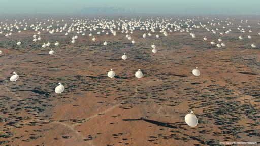
13 ANTENNA TECHNOLOGIES MWA MHz. Steered by phasing fixed elements MeerKAT prototype 15m composite antenna (South Africa)
14 LOCATION Location is an important decision with large performance, operations, financial, and political considerations At high frequencies, want high altitude and dry climate (ALMA) At low frequencies, want protection from RFI (SKA) At low frequencies, avoid regions with worst ionosphere (SKA etc) Site must be large enough to accommodate the array Need reasonable access and place to live for staff and their families Not everyone can work remotely Need power, communications. Expensive if need to provide own, especially to outer stations.

15 IONOSPHERE Can seriously complicate the calibration of low frequency data Concentrated near the subsolar point but on the geomagnetic equator
16 TROPOSPHERE At high frequencies, the troposphere is the main problem for calibration The tropospheric delay is dominated by the dry atmosphere But that is fairly stable Water vapor is highly variable, so limits phase stability For a high frequency array, chose a site with low water vapor Want an arid location at high altitude EVLA at 2114 m ALMA at 5000 m in the Atacama Desert Want phase stability Usually, but not always correlates with opacity
17 RADIO FREQUENCY INTERFERENCE RFI is a big problem especially on short baselines at low frequencies. Non-closing corruption of data Time variable Corruption of spectra It is becoming more of a problem at high frequencies Want isolation from civilization Want terrain shielding (surrounding mountains good) Can t hide from satellites Problem is reduced for long baselines Sources different at each antenna - done correlate Attenuated by high fringe rates (differential Doppler shifts) But can saturate receivers
18 RFI EXAMPLES
19 SITE CONSTRAINTS Sites for all antennas need to be chosen together for good UV coverage Site issues vary on different scales For short baselines (10s of km), want large flat area Full freedom to position antennas as desired For 10s to 100s of km, will need individual sites Need to conform to power, communication, road access Need to avoid cities, wilderness areas, military areas The sites will need to be within a few km of the desired position for the configuration, but many configurations work For long baselines, site position not critical to 10s or 100s of km Usually can find some place that works Main constraints are major geographic features like oceans
20 NUMBER OF ANTENNAS AND SITES Sensitivity issues Required sensitivity Required field of view or survey speed Cost optimization - N vs D Imaging issues Required baseline range and UV coverage Types and complexity of target sources Impact of confusion Each antenna separate or clusters? May depend on distance from center May be cost and correlator size driven

21 RECONFIGURE? Allows wide baseline range with fewer antennas EVLA 1km to 35km arrays - 27 antennas but 72 pads Constrains observing to certain times by resolution Requires some sort of transporter SKA not planned to reconfigure Configurations (EVLA) vs continuous zoom (ALMA) ALMA transporter
22 CONFIGURATION Must determine where to put the antennas Goals Obtain adequate UV coverage to meet the scientific goals Minimize cost - probably means minimize separate stations Constraints Available geography Available infrastructure (power, communication, roads) What are the required properties and capabilities? Snapshot coverage or only full tracks Brightness sensitivity and resolution range Implies baseline range Centrally condensed or more uniform distribution Reconfigurable? Once configuration is chosen, can t freely move individual antennas Optimizing baselines
23 UV COVERAGE: SINGLE SHORT BASELINE A single baseline has a sinusoidal sensitivity pattern across the sky, oscillating between constructive and destructive interference.
24 UV COVERAGE: SINGLE LONG BASELINE The oscillations in the sensitivity pattern have the same direction as the baseline, with a period determined by the baseline length in wavelengths
25 UV COVERAGE: SNAPSHOT The uv-coverage is the set of all baseline vectors. The synthesized beam (PSF) is the sensitivity pattern of all baselines.

26 UV COVERAGE: SHORT TRACK 1 Hour Synthesis Observation
27 UV COVERAGE: MEDIUM TRACK 3 Hour Synthesis Observation

28 UV COVERAGE: FULL TRACK 12 Hour Synthesis Observation

29 EXAMPLES: Westerbork Synthesis Radio Telescope (WSRT) Located in Westerbork, Holland Has 14 antennas, 25m diameter East-West Array Requires Earth Rotation Synthesis for all imaging Dedicated in 1970: one of the earliest major interferometric arrays

30 EXAMPLES: WSRT WSRT uv-coverage at various declinations
 B min (km)! A 36 0.")
31 EXAMPLES: Very Large Array (VLA)! Y-shaped Array Re-configurable Config. B max (km) B min (km)! A B C D

32 EXAMPLES: VLA LONG TRACK VLA uv-coverage at various declinations

33 EXAMPLES: Very Long Baseline Array (VLBA) Ten 25m antennas US Territory, Hawaii to St. Croix Baselines 200 to 8,600 km Elements not connected Separate clocks Data recorded Resolution of milliarcseconds

34 EXAMPLES: VLBA VLBA uv-coverage at various declinations


35 VARIOUS IDEAL ARRAY DESIGNS Circular maximizes number of long baselines Spiral has more short baselines Random has little redundancy or patterns Spiral Design: N = 45 Circular Design: N = 45 Random Design: N = 45

36 Centrally Condensed Array Plots for EVLA2 (NMA) VLA + 10, to 300km Mainly baselines from outer stations to core count SKA will be centrally condensed Hard to get full resolution and full sensitivity together
37 LARGE-N / SMALL-D CONCEPT N = Number of antennas in array D = Diameter of an antenna Collecting area (N D 2 ) kept constant UV Coverage drastically improved keeping sensitivity constant Number of baselines scales with N 2 Field of view large - better for survey speed Antennas relatively inexpensive - cost effective way to get area But the electronics are more complicated and expensive Many more receivers, LOs, data lines etc Correlator scales with N 2 ATA is exploring the concept SKA will likely use it with several thousand antennas

38 SKA CONCEPTUAL CONFIGURATION About 3000 antennas Core of 5 km diameter Dense array of 1500 individual antennas Skirt 2.5 to 15 km radius Transition to spirals 372 antennas Intermediate region km Skirt is inner part 528 antennas in clumps of 11 beyond skirt Remote region km 600 antennas in clumps of 24 Displays from AntConfig - program being used to derive SKA configuration

39 SKA CONCEPTUAL CONFIGURATION About 3000 antennas Core of 5 km diameter Dense array of 1500 individual antennas Skirt 2.5 to 15 km radius Transition to spirals 372 antennas Intermediate region km Skirt is inner part 528 antennas in clumps of 11 beyond skirt Remote region km 600 antennas in clumps of 24 Displays from AntConfig - program being used to derive SKA configuration

40 SKA CONCEPTUAL CONFIGURATION About 3000 antennas Core of 5 km diameter Dense array of 1500 individual antennas Skirt 2.5 to 15 km radius Transition to spirals 372 antennas Intermediate region km Skirt is inner part 528 antennas in clumps of 11 beyond skirt Remote region km 600 antennas in clumps of 24 Displays from AntConfig - program being used to derive SKA configuration
41 SKA CONCEPTUAL CONFIGURATION About 3000 antennas Core of 5 km diameter Dense array of 1500 individual antennas Skirt 2.5 to 15 km radius Transition to spirals 372 antennas Intermediate region km Skirt is inner part 528 antennas in clumps of 11 beyond skirt Remote region km 600 antennas in clumps of 24 Displays from AntConfig - program being used to derive SKA configuration
42 SKA CONCEPTUAL CONFIGURATION About 3000 antennas Core of 5 km diameter Dense array of 1500 individual antennas Skirt 2.5 to 15 km radius Transition to spirals 372 antennas Intermediate region km Skirt is inner part 528 antennas in clumps of 11 beyond skirt Remote region km 600 antennas in clumps of 24 Displays from AntConfig - program being used to derive SKA configuration
43 ARRAY OPTIMIZATION Trial and Error devise configurations and calculate metrics (works OK for small N)! Random Distribution Lack of geometric pattern reduces redundancy Works surprisingly well for large N Simulated Annealing (Cornwell)! Define uv energy function to minimize log of mean uv distance UV-Density & pressure (Boone)! Steepest descent gradient search to minimize uv density differences with ideal uv density (e.g., Gaussian)! Genetic algorithm (e.g., Cohanim et al.,2004)! Pick start configurations, breed new generation using crossover and mutation, select, repeat PSF optimization (L. Kogan) Minimize biggest sidelobe using derivatives of beam with respect to antenna locations (iterative process)!
44 METRICS FOR OPTIMIZATION Side-lobe levels Useful for image dynamic range Range of baseline lengths Useful for large complex sources Useful for ability to support a wide variety of science Largest gaps in uv-coverage Image fidelity Match to desired baseline length distribution So that UV-weighting, which reduces sensitivity, is not needed


45 Iterative Minimization of Sidelobes: Kogan Method Comparing random versus optimized arrays for N = 271

46 MASK In the optimization, a mask can be used to define acceptable places to put antennas Example is for ALMA Pads can go in the white areas Preparation of a mask is an important step Time consuming to get all the required data
47 SIMULATIONS Simulations provide a good test and demonstration of an array design Show how well the UV-coverage performs in practice Can explore fidelity since the true image is known Provide material to help sell the array Steps for a simulation: Generate realistic models of sky Simulate data, adding in increasing levels of reality Atmosphere, pointing errors, dish surface rms etc. Process simulated data & compare final images for different designs and configurations relative comparison Compare final images with input model Tests image fidelity which cannot be done with real data Compare with specifications for DR and fidelity Be careful that you are not just testing imaging methods rather than array design - imaging is a complicated process
!")

48 Simulating the Long Wavelength Array (LWA)! Cygnus A at 325 MHz with VLA A-configuration + PT Simulated LWIA Image (74 MHz)! Simulating Image Fidelity Project model image to simulated uv-coverage and image in normal way Subtract model to examine residual image errors Can define: Fidelity Index = (peak intensity)/(residual rms)! Residual Map (model subtracted)!
49 SIMULATION SOFTWARE Most analysis packages have basic simulation capabilities AIPS - Basic fake data creation with full imaging and analysis CASA - simdata and sm Can simulate many arrays. including ALMA, EVLA, CARMA, SMA, ATCA, PdB. MeqTrees - Implements measurement equations Used especially for LOFAR ASKAPSoft - includes support for multi-beam systems IRAM/GILDAS ALMA simulator Many more
50 THE END
Array Configuration for the Long Wavelength Intermediate Array (LWIA): Choosing the First Four Station Sites
: Choosing the First Four Station Sites") Array Configuration for the Long Wavelength Intermediate Array (LWIA): Choosing the First Four Station Sites Aaron Cohen (NRL) and Greg Taylor (UNM) December 4, 2007 ABSTRACT The Long Wavelength Intermediate
Array Configuration for the Long Wavelength Intermediate Array (LWIA): Choosing the First Four Station Sites Aaron Cohen (NRL) and Greg Taylor (UNM) December 4, 2007 ABSTRACT The Long Wavelength Intermediate
Radio Interferometers Around the World. Amy J. Mioduszewski (NRAO)
") Radio Interferometers Around the World Amy J. Mioduszewski (NRAO) A somewhat biased view of current interferometers Limited to telescopes that exist or are in the process of being built (i.e., I am not
Radio Interferometers Around the World Amy J. Mioduszewski (NRAO) A somewhat biased view of current interferometers Limited to telescopes that exist or are in the process of being built (i.e., I am not
More Radio Astronomy
 More Radio Astronomy Radio Telescopes - Basic Design A radio telescope is composed of: - a radio reflector (the dish) - an antenna referred to as the feed on to which the radiation is focused - a radio
A model for the SKA. Melvyn Wright. Radio Astronomy laboratory, University of California, Berkeley, CA, ABSTRACT
 SKA memo 16. 21 March 2002 A model for the SKA Melvyn Wright Radio Astronomy laboratory, University of California, Berkeley, CA, 94720 ABSTRACT This memo reviews the strawman design for the SKA telescope.
Wide-Band Imaging. Outline : CASS Radio Astronomy School Sept 2012 Narrabri, NSW, Australia. - What is wideband imaging?
 Wide-Band Imaging 24-28 Sept 2012 Narrabri, NSW, Australia Outline : - What is wideband imaging? - Two Algorithms Urvashi Rau - Many Examples National Radio Astronomy Observatory Socorro, NM, USA 1/32
Next Generation Very Large Array Memo No. 16 More on Synthesized Beams and Sensitivity. C.L. Carilli, NRAO, PO Box O, Socorro, NM
 Next Generation Very Large Array Memo No. 16 More on Synthesized Beams and Sensitivity C.L. Carilli, NRAO, PO Box O, Socorro, NM Abstract I present further calculations on synthesized beams and sensitivities
SKA1 low Baseline Design: Lowest Frequency Aspects & EoR Science
 SKA1 low Baseline Design: Lowest Frequency Aspects & EoR Science 1 st science Assessment WS, Jodrell Bank P. Dewdney Mar 27, 2013 Intent of the Baseline Design Basic architecture: 3-telescope, 2-system
Propagation effects (tropospheric and ionospheric phase calibration)
") Propagation effects (tropospheric and ionospheric phase calibration) Prof. Steven Tingay Curtin University of Technology Perth, Australia With thanks to Alan Roy (MPIfR), James Anderson (JIVE), Tasso Tzioumis
Propagation effects (tropospheric and ionospheric phase calibration) Prof. Steven Tingay Curtin University of Technology Perth, Australia With thanks to Alan Roy (MPIfR), James Anderson (JIVE), Tasso Tzioumis
Overview of the SKA. P. Dewdney International SKA Project Engineer Nov 9, 2009
 Overview of the SKA P. Dewdney International SKA Project Engineer Nov 9, 2009 Outline* 1. SKA Science Drivers. 2. The SKA System. 3. SKA technologies. 4. Trade-off space. 5. Scaling. 6. Data Rates & Data
Plan for Imaging Algorithm Research and Development
 Plan for Imaging Algorithm Research and Development S. Bhatnagar July 05, 2009 Abstract Many scientific deliverables of the next generation radio telescopes require wide-field imaging or high dynamic range
Next Generation Very Large Array Memo No. 47 Resolution and Sensitivity of ngvla-revb. C.L. Carilli (NRAO)
") Next Generation Very Large Array Memo No. 47 Resolution and Sensitivity of ngvla-revb C.L. Carilli (NRAO) Abstract I investigate the noise performance vs. resolution for the new ngvlarevb configuration.
Next Generation Very Large Array Memo No. 47 Resolution and Sensitivity of ngvla-revb C.L. Carilli (NRAO) Abstract I investigate the noise performance vs. resolution for the new ngvlarevb configuration.
3 rd (and 4 th ) Generation Calibration. Jan Noordam ASTRON Oude Hoogeveensedijk 4, 7991 PD Dwingeloo, The Netherlands. J.E.
 Generation Calibration. Jan Noordam ASTRON Oude Hoogeveensedijk 4, 7991 PD Dwingeloo, The Netherlands. J.E.") 3 rd (and 4 th ) Generation Calibration Jan Noordam ASTRON Oude Hoogeveensedijk 4, 7991 PD Dwingeloo, The Netherlands - 1 - The structure of this talk Posted title: The Minimum Ionospheric Model. This
3 rd (and 4 th ) Generation Calibration Jan Noordam ASTRON Oude Hoogeveensedijk 4, 7991 PD Dwingeloo, The Netherlands - 1 - The structure of this talk Posted title: The Minimum Ionospheric Model. This
Very Long Baseline Interferometry
 Very Long Baseline Interferometry Cormac Reynolds, JIVE European Radio Interferometry School, Bonn 12 Sept. 2007 VLBI Arrays EVN (Europe, China, South Africa, Arecibo) VLBA (USA) EVN + VLBA coordinate
Introduction to Interferometry. Michelson Interferometer. Fourier Transforms. Optics: holes in a mask. Two ways of understanding interferometry
 Introduction to Interferometry P.J.Diamond MERLIN/VLBI National Facility Jodrell Bank Observatory University of Manchester ERIS: 5 Sept 005 Aim to lay the groundwork for following talks Discuss: General
INTERFEROMETRY: II Nissim Kanekar (NCRA TIFR)
") INTERFEROMETRY: II Nissim Kanekar (NCRA TIFR) WSRT GMRT VLA ATCA ALMA SKA MID PLAN Introduction. The van Cittert Zernike theorem. A 2 element interferometer. The fringe pattern. 2 D and 3 D interferometers.
INTERFEROMETRY: II Nissim Kanekar (NCRA TIFR) WSRT GMRT VLA ATCA ALMA SKA MID PLAN Introduction. The van Cittert Zernike theorem. A 2 element interferometer. The fringe pattern. 2 D and 3 D interferometers.
Introduction to Radioastronomy: Interferometers and Aperture Synthesis
 Introduction to Radioastronomy: Interferometers and Aperture Synthesis J.Köppen joachim.koppen@astro.unistra.fr http://astro.u-strasbg.fr/~koppen/jkhome.html Problem No.2: Angular resolution Diffraction
Comparing MMA and VLA Capabilities in the GHz Band. Socorro, NM Abstract
 Comparing MMA and VLA Capabilities in the 36-50 GHz Band M.A. Holdaway National Radio Astronomy Observatory Socorro, NM 87801 September 29, 1995 Abstract I explore the capabilities of the MMA and the VLA,
EVLA and LWA Imaging Challenges
 EVLA and LWA Imaging Challenges Steven T. Myers IGPP, Los Alamos National Laboratory and National Radio Astronomy Observatory, Socorro, NM 1 EVLA key issues 2 Key algorithmic issues ambitious goals / hard
The Square Kilometer Array Preliminary Strawman Design Large N - Small D. prepared by the. USSKA Consortium. Table of Contents. Executive Summary...
 The Square Kilometer Array Preliminary Strawman Design Large N - Small D prepared by the USSKA Consortium Table of Contents Executive Summary................................... 2 1. Introduction... 64424
Radio Interferometry. Xuening Bai. AST 542 Observational Seminar May 4, 2011
 Radio Interferometry Xuening Bai AST 542 Observational Seminar May 4, 2011 Outline Single-dish radio telescope Two-element interferometer Interferometer arrays and aperture synthesis Very-long base line
GPU based imager for radio astronomy
 GPU based imager for radio astronomy GTC2014, San Jose, March 27th 2014 S. Bhatnagar, P. K. Gupta, M. Clark, National Radio Astronomy Observatory, NM, USA NVIDIA-India, Pune NVIDIA-US, CA Introduction
Wide Bandwidth Imaging
 Wide Bandwidth Imaging 14th NRAO Synthesis Imaging Workshop 13 20 May, 2014, Socorro, NM Urvashi Rau National Radio Astronomy Observatory 1 Why do we need wide bandwidths? Broad-band receivers => Increased
Phased Array Feeds & Primary Beams
 Phased Array Feeds & Primary Beams Aidan Hotan ASKAP Deputy Project Scientist 3 rd October 2014 CSIRO ASTRONOMY AND SPACE SCIENCE Outline Review of parabolic (dish) antennas. Focal plane response to a
Imaging Simulations with CARMA-23
 BIMA memo 101 - July 2004 Imaging Simulations with CARMA-23 M. C. H. Wright Radio Astronomy laboratory, University of California, Berkeley, CA, 94720 ABSTRACT We simulated imaging for the 23-antenna CARMA
James M Anderson. in collaboration with Jan Noordam and Oleg Smirnov. MPIfR, Bonn, 2006 Dec 07
 Ionospheric Calibration for Long-Baseline, Low-Frequency Interferometry in collaboration with Jan Noordam and Oleg Smirnov Page 1/36 Outline The challenge for radioastronomy Introduction to the ionosphere
Sideband Smear: Sideband Separation with the ALMA 2SB and DSB Total Power Receivers
 and DSB Total Power Receivers SCI-00.00.00.00-001-A-PLA Version: A 2007-06-11 Prepared By: Organization Date Anthony J. Remijan NRAO A. Wootten T. Hunter J.M. Payne D.T. Emerson P.R. Jewell R.N. Martin
Introduction to Imaging in CASA
 Introduction to Imaging in CASA Mark Rawlings, Juergen Ott (NRAO) Atacama Large Millimeter/submillimeter Array Expanded Very Large Array Robert C. Byrd Green Bank Telescope Very Long Baseline Array Overview
Planning ALMA Observations
 Planning Observations Atacama Large mm/sub-mm Array Mark Lacy North American Science Center Atacama Large Millimeter/submillimeter Array Expanded Very Large Array Robert C. Byrd Green Bank Telescope Very
LOFAR: Special Issues
 Netherlands Institute for Radio Astronomy LOFAR: Special Issues John McKean (ASTRON) ASTRON is part of the Netherlands Organisation for Scientific Research (NWO) 1 Preamble http://www.astron.nl/~mckean/eris-2011-2.pdf
VERY LONG BASELINE INTERFEROMETRY
 VERY LONG BASELINE INTERFEROMETRY Summer Student Lecture Socorro, June 28, 2011 Adapted from 2004 Summer School Lecture and 2005, 2007, and 2009 Summer Student Lectures WHAT IS VLBI? 2 Radio interferometry
When, why and how to self-cal Nathan Brunetti, Crystal Brogan, Amanda Kepley
 When, why and how to self-cal Nathan Brunetti, Crystal Brogan, Amanda Kepley Atacama Large Millimeter/submillimeter Array Expanded Very Large Array Robert C. Byrd Green Bank Telescope Very Long Baseline
Radio Data Archives. how to find, retrieve, and image radio data: a lay-person s primer. Michael P Rupen (NRAO)
") Radio Data Archives how to find, retrieve, and image radio data: a lay-person s primer Michael P Rupen (NRAO) By the end of this talk, you should know: The standard radio imaging surveys that provide FITS
Radio Data Archives how to find, retrieve, and image radio data: a lay-person s primer Michael P Rupen (NRAO) By the end of this talk, you should know: The standard radio imaging surveys that provide FITS
How to SPAM the 150 MHz sky
 How to SPAM the 150 MHz sky Huib Intema Leiden Observatory 26/04/2016 Main collaborators: Preshanth Jagannathan (UCT/NRAO) Kunal Mooley (Oxford) Dale Frail (NRAO) Talk outline The need for a low-frequency
The discrete charms of Redundant Spacing Calibration (RSC) J.E.Noordam. Madroon Community Consultants (MCC)
 J.E.Noordam. Madroon Community Consultants (MCC)") The discrete charms of Redundant Spacing Calibration (RSC) J.E.Noordam Madroon Community Consultants (MCC) Outline What is RSC? Advantages Limitations The place of RSC in the GST Diagnostic tool Fast first
The discrete charms of Redundant Spacing Calibration (RSC) J.E.Noordam Madroon Community Consultants (MCC) Outline What is RSC? Advantages Limitations The place of RSC in the GST Diagnostic tool Fast first
Introduction to Radio Astronomy. Richard Porcas Max-Planck-Institut fuer Radioastronomie, Bonn
 Introduction to Radio Astronomy Richard Porcas Max-Planck-Institut fuer Radioastronomie, Bonn 1 Contents Radio Waves Radio Emission Processes Radio Noise Radio source names and catalogues Radio telescopes
Spectral Line Observing
 Spectral Line Observing Ylva Pihlström, UNM Eleventh Synthesis Imaging Workshop Socorro, June 10-17, 2008 Introduction 2 Spectral line observers use many channels of width δν, over a total bandwidth Δν.
VLBI Post-Correlation Analysis and Fringe-Fitting
 VLBI Post-Correlation Analysis and Fringe-Fitting Michael Bietenholz With (many) Slides from George Moellenbroek and Craig Walker NRAO Calibration is important! What Is Delivered by a Synthesis Array?
Components of Imaging at Low Frequencies: Status & Challenges
 Components of Imaging at Low Frequencies: Status & Challenges Dec. 12th 2013 S. Bhatnagar NRAO Collaborators: T.J. Cornwell, R. Nityananda, K. Golap, U. Rau J. Uson, R. Perley, F. Owen Telescope sensitivity
November SKA Low Frequency Aperture Array. Andrew Faulkner
 SKA Phase 1 Implementation Southern Africa Australia SKA 1 -mid 250 15m dia. Dishes 0.4-3GHz SKA 1 -low 256,000 antennas Aperture Array Stations 50 350/650MHz SKA 1 -survey 90 15m dia. Dishes 0.7-1.7GHz
High Fidelity Imaging of Extended Sources. Rick Perley NRAO Socorro, NM
 High Fidelity Imaging of Extended Sources Rick Perley NRAO Socorro, NM A Brief History of Calibration (VLA) An Amazing Fact: The VLA was proposed, and funded, without any real concept of how to calibrate
Technology Drivers, SKA Pathfinders P. Dewdney
 Technology Drivers, SKA Pathfinders P. Dewdney Dominion Radio Astrophysical Observatory Herzberg Institute of Astrophysics National Research Council Canada National Research Council Canada Conseil national
Roshene McCool Domain Specialist in Signal Transport and Networks SKA Program Development Office
 Roshene McCool Domain Specialist in Signal Transport and Networks SKA Program Development Office mccool@skatelescope.org SKA A description Outline Specifications Long Baselines in the SKA Science drivers
LWA Station Design. S. Ellingson, Virginia Tech N. Kassim, U.S. Naval Research Laboratory. URSI General Assembly Chicago Aug 11, 2008 JPL
 LWA Station Design S. Ellingson, Virginia Tech N. Kassim, U.S. Naval Research Laboratory URSI General Assembly Chicago Aug 11, 2008 JPL Long Wavelength Array (LWA) An LWA Station State of New Mexico, USA
Radio Interferometry -- II
 Radio Interferometry -- II Rick Perley, NRAO/Socorro ATNF School on Radio Astronomy Narrabri, NSW 29 Sept 3 Oct, 2014 Topics Practical Extensions to the Theory: Finite bandwidth Rotating reference frames
LOFAR Long Baseline Calibration Commissioning
 LOFAR Long Baseline Calibration Commissioning anderson@mpifr-bonn.mpg.de On behalf of LOFAR and the LLBWG 1/31 No, No Fringes On Long Baseline Yet... I hate pretending to be an optimist when writing abstract
Imaging and Calibration Algorithms for EVLA, e-merlin and ALMA. Robert Laing ESO
 Imaging and Calibration Algorithms for EVLA, e-merlin and ALMA Socorro, April 3 2008 Workshop details Oxford, 2008 Dec 1-3 Sponsored by Radionet and the University of Oxford 56 participants http://astrowiki.physics.ox.ac.uk/cgi-bin/twiki/view/algorithms2008/webhome
Why? When? How What to do What to worry about
 Tom Muxlow Data Combination Why? When? How What to do What to worry about Combination imaging or separate imaging??..using (e-)merlin (e-)merlin covers a unique range of telescope separations, intermediate
Wide-field, wide-band and multi-scale imaging - II
 Wide-field, wide-band and multi-scale imaging - II Radio Astronomy School 2017 National Centre for Radio Astrophysics / TIFR Pune, India 28 Aug 8 Sept, 2017 Urvashi Rau National Radio Astronomy Observatory,
ASTRO 6525 Lecture #18:! (Sub-)Millimeter Interferometry I!! October 27, 2015!
Millimeter Interferometry I!! October 27, 2015!") ASTRO 6525 Lecture #18:! (Sub-)Millimeter Interferometry I!! October 27, 2015! Dominik A. Riechers Find me at office SSB 220 E-mail: dr@astro.cornell.edu Schedule for this Section Today: Introduction to
ASTRO 6525 Lecture #18:! (Sub-)Millimeter Interferometry I!! October 27, 2015! Dominik A. Riechers Find me at office SSB 220 E-mail: dr@astro.cornell.edu Schedule for this Section Today: Introduction to
Planning (VLA) observations
 observations") Planning () observations 14 th Synthesis Imaging Workshop (May 2014) Loránt Sjouwerman National Radio Astronomy Observatory (Socorro, NM) Atacama Large Millimeter/submillimeter Array Karl G. Jansky Very
Planning () observations 14 th Synthesis Imaging Workshop (May 2014) Loránt Sjouwerman National Radio Astronomy Observatory (Socorro, NM) Atacama Large Millimeter/submillimeter Array Karl G. Jansky Very
Phased Array Feeds A new technology for multi-beam radio astronomy
 Phased Array Feeds A new technology for multi-beam radio astronomy Aidan Hotan ASKAP Deputy Project Scientist 2 nd October 2015 CSIRO ASTRONOMY AND SPACE SCIENCE Outline Review of radio astronomy concepts.
LOFAR update: long baselines and other random topics
 LOFAR update: long baselines and other random topics AIfA/MPIfR lunch colloquium Olaf Wucknitz wucknitz@astro.uni-bonn.de Bonn, 6th April 20 LOFAR update: long baselines and other random topics LOFAR previous
Practicalities of Radio Interferometry
 Practicalities of Radio Interferometry Rick Perley, NRAO/Socorro 13 th Synthesis Imaging Summer School 29 May 5 June, 2012 Socorro, NM Topics Practical Extensions to the Theory: Finite bandwidth Rotating
Phased Array Feeds A new technology for wide-field radio astronomy
 Phased Array Feeds A new technology for wide-field radio astronomy Aidan Hotan ASKAP Project Scientist 29 th September 2017 CSIRO ASTRONOMY AND SPACE SCIENCE Outline Review of radio astronomy concepts
Large-field imaging. Frédéric Gueth, IRAM Grenoble. 7th IRAM Millimeter Interferometry School 4 8 October 2010
 Large-field imaging Frédéric Gueth, IRAM Grenoble 7th IRAM Millimeter Interferometry School 4 8 October 2010 Large-field imaging The problems The field of view is limited by the antenna primary beam width
EVLA Scientific Commissioning and Antenna Performance Test Check List
 EVLA Scientific Commissioning and Antenna Performance Test Check List C. J. Chandler, C. L. Carilli, R. Perley, October 17, 2005 The following requirements come from Chapter 2 of the EVLA Project Book.
Radio Astronomy: SKA-Era Interferometry and Other Challenges. Dr Jasper Horrell, SKA SA (and Dr Oleg Smirnov, Rhodes and SKA SA)
") Radio Astronomy: SKA-Era Interferometry and Other Challenges Dr Jasper Horrell, SKA SA (and Dr Oleg Smirnov, Rhodes and SKA SA) ASSA Symposium, Cape Town, Oct 2012 Scope SKA antenna types Single dishes
Radio Astronomy: SKA-Era Interferometry and Other Challenges Dr Jasper Horrell, SKA SA (and Dr Oleg Smirnov, Rhodes and SKA SA) ASSA Symposium, Cape Town, Oct 2012 Scope SKA antenna types Single dishes
VLBI2010: In search of Sub-mm Accuracy
 VLBI2010: In search of Sub-mm Accuracy Bill Petrachenko, Nov 6, 2007, University of New Brunswick What is VLBI2010? VLBI2010 is an effort by the International VLBI Service for Geodesy and Astrometry (IVS)
Parameterized Deconvolution for Wide-Band Radio Synthesis Imaging
 Parameterized Deconvolution for Wide-Band Radio Synthesis Imaging Urvashi Rao Venkata Ph.D. Thesis Defense Department of Physics, New Mexico Institute of Mining and Technology 17 May 2010 Advisors / Committee
Dense Aperture Array for SKA
 Dense Aperture Array for SKA Steve Torchinsky EMBRACE Why a Square Kilometre? Detection of HI in emission at cosmological distances R. Ekers, SKA Memo #4, 2001 P. Wilkinson, 1991 J. Heidmann, 1966! SKA
Smart Antennas in Radio Astronomy
 Smart Antennas in Radio Astronomy Wim van Cappellen cappellen@astron.nl Netherlands Institute for Radio Astronomy Our mission is to make radio-astronomical discoveries happen ASTRON is an institute for
(The basics of) VLBI Basics. Pedro Elosegui MIT Haystack Observatory. With big thanks to many of you, here and out there
 VLBI Basics. Pedro Elosegui MIT Haystack Observatory. With big thanks to many of you, here and out there") (The basics of) VLBI Basics Pedro Elosegui MIT Haystack Observatory With big thanks to many of you, here and out there Some of the Points Will Cover Today Geodetic radio telescopes VLBI vs GPS concept
(The basics of) VLBI Basics Pedro Elosegui MIT Haystack Observatory With big thanks to many of you, here and out there Some of the Points Will Cover Today Geodetic radio telescopes VLBI vs GPS concept
Fundamentals of Radio Interferometry
 Fundamentals of Radio Interferometry Rick Perley, NRAO/Socorro Fourteenth NRAO Synthesis Imaging Summer School Socorro, NM Topics Why Interferometry? The Single Dish as an interferometer The Basic Interferometer
May AA Communications. Portugal
 SKA Top-level description A large radio telescope for transformational science Up to 1 million m 2 collecting area Operating from 70 MHz to 10 GHz (4m-3cm) Two or more detector technologies Connected to
EVLA Memo 105. Phase coherence of the EVLA radio telescope
 EVLA Memo 105 Phase coherence of the EVLA radio telescope Steven Durand, James Jackson, and Keith Morris National Radio Astronomy Observatory, 1003 Lopezville Road, Socorro, NM, USA 87801 ABSTRACT The
Practical Radio Interferometry VLBI. Olaf Wucknitz.
 Practical Radio Interferometry VLBI Olaf Wucknitz wucknitz@astro.uni-bonn.de Bonn, 1 December 2010 VLBI Need for long baselines What defines VLBI? Techniques VLBI science Practical issues VLBI arrays how
Volume 82 VERY LONG BASELINE INTERFEROMETRY AND THE VLBA. J. A. Zensus, P. J. Diamond, and P. J. Napier
 ASTRONOMICAL SOCIETY OF THE PACIFIC CONFERENCE SERIES Volume 82 VERY LONG BASELINE INTERFEROMETRY AND THE VLBA Proceedings of a Summer School held in Socorro, New Mexico 23-30 June 1993 NRAO Workshop No.
ARRAY CONFIGURATION AND TOTAL POWER CALIBRATION FOR LEDA
 ARRAY CONFIGURATION AND TOTAL POWER CALIBRATION FOR LEDA Frank Schinzel & Joe Craig (UNM) on behalf of the LEDA Collaboration USNC-URSI National Radio Science Meeting 2013 - Boulder, 09.01.2013 What is
The WVR at Effelsberg. Thomas Krichbaum
 The WVR at Effelsberg Alan Roy Ute Teuber Helge Rottmann Thomas Krichbaum Reinhard Keller Dave Graham Walter Alef The Scanning 18-26 GHz WVR for Effelsberg ν = 18.5 GHz to 26.0 GHz Δν = 900 MHz Channels
Cormac Reynolds. ATNF Synthesis Imaging School, Narrabri 10 Sept. 2008
 Very Long Baseline Interferometry Cormac Reynolds ATNF 10 Sept. 2008 Outline Very brief history Data acquisition Calibration Applications Acknowledgements: C. Walker, S. Tingay What Is VLBI? VLBI: Very
Workshop Summary: RFI and its impact on the new generation of HI spectral-line surveys
 Workshop Summary: RFI and its impact on the new generation of HI spectral-line surveys Lisa Harvey-Smith 19 th June 2013 ASTRONONY & SPACE SCIENCE Workshop Rationale How will RFI impact HI spectral line
The Basics of Radio Interferometry. Frédéric Boone LERMA, Observatoire de Paris
 The Basics of Radio Interferometry LERMA, Observatoire de Paris The Basics of Radio Interferometry The role of interferometry in astronomy = role of venetian blinds in Film Noir 2 The Basics of Radio Interferometry
ALMA Phase Calibration, Phase Correction and the Water Vapour Radiometers
 ALMA Phase Calibration, Phase Correction and the Water Vapour Radiometers B. Nikolic 1, J. S. Richer 1, R. E. Hills 1,2 1 MRAO, Cavendish Lab., University of Cambridge 2 Joint ALMA Office, Santiago, Chile
Low Frequency Radio Astronomy from the Lunar Surface
 Low Frequency Radio Astronomy from the Lunar Surface R. J. MacDowall (1), T. J. Lazio (2), J. Burns (3) (1) NASA/GSFC, Greenbelt, MD, USA (2) JPL/Caltech, Pasadena, CA, USA (3) U. Colorado, Boulder, CO,
Technical Considerations: Nuts and Bolts Project Planning and Technical Justification
 Technical Considerations: Nuts and Bolts Project Planning and Technical Justification Atacama Large Millimeter/submillimeter Array Expanded Very Large Array Robert C. Byrd Green Bank Telescope Very Long
ngvla Technical Overview
 ngvla Technical Overview Mark McKinnon, Socorro, NM Outline ngvla Nominal Technical Parameters Technical Issues to Consider in Science Use Cases Programmatics Additional Information Pointed or Survey Telescope?
Detrimental Interference Levels at Individual LWA Sites LWA Engineering Memo RFS0012
 Detrimental Interference Levels at Individual LWA Sites LWA Engineering Memo RFS0012 Y. Pihlström, University of New Mexico August 4, 2008 1 Introduction The Long Wavelength Array (LWA) will optimally
Practicalities of Radio Interferometry
 Practicalities of Radio Interferometry Rick Perley, NRAO/Socorro Fourth INPE Course in Astrophysics: Radio Astronomy in the 21 st Century Topics Practical Extensions to the Theory: Finite bandwidth Rotating
Chapter 5. Array of Star Spirals
 Chapter 5. Array of Star Spirals The star spiral was introduced in the previous chapter and it compared well with the circular Archimedean spiral. This chapter will examine the star spiral in an array
ASKAP Industry technical briefing. Tim Cornwell, ASKAP Computing Project Lead Australian Square Kilometre Array Pathfinder
 ! ASKAP Industry technical briefing Tim Cornwell, ASKAP Computing Project Lead Australian Square Kilometre Array Pathfinder The Square Kilometre Array 2020 era radio telescope Very large collecting area
LOFAR: From raw visibilities to calibrated data
 Netherlands Institute for Radio Astronomy LOFAR: From raw visibilities to calibrated data John McKean (ASTRON) [subbing in for Manu] ASTRON is part of the Netherlands Organisation for Scientific Research
Recent imaging results with wide-band EVLA data, and lessons learnt so far
 Recent imaging results with wide-band EVLA data, and lessons learnt so far Urvashi Rau National Radio Astronomy Observatory (USA) 26 Jul 2011 (1) Introduction : Imaging wideband data (2) Wideband Imaging
Introduction to Radio Astronomy
 Introduction to Radio Astronomy The Visible Sky, Sagittarius Region 2 The Radio Sky 3 4 Optical and Radio can be done from the ground! 5 Outline The Discovery of Radio Waves Maxwell, Hertz and Marconi
Antennas & Receivers in Radio Astronomy
 Antennas & Receivers in Radio Astronomy Mark McKinnon Fifteenth Synthesis Imaging Workshop 1-8 June 2016 Purpose & Outline Purpose: describe how antenna elements can affect the quality of images produced
Recent progress in EVLA-specific algorithms. EVLA Advisory Committee Meeting, March 19-20, S. Bhatnagar and U. Rau
 Recent progress in EVLA-specific algorithms EVLA Advisory Committee Meeting, March 19-20, 2009 S. Bhatnagar and U. Rau Imaging issues Full beam, full bandwidth, full Stokes noise limited imaging Algorithmic
Real Time Imaging. Melvyn Wright. Radio Astronomy Laboratory, University of California, Berkeley, CA, ABSTRACT
 SKA MEMO 60, 24 May 2005 Real Time Imaging Melvyn Wright Radio Astronomy Laboratory, University of California, Berkeley, CA, 94720 ABSTRACT In this paper, we propose to integrate the imaging process with
March Phased Array Technology. Andrew Faulkner
 Aperture Arrays Michael Kramer Sparse Type of AA selection 1000 Sparse AA-low Sky Brightness Temperature (K) 100 10 T sky A eff Fully sampled AA-mid Becoming sparse Aeff / T sys (m 2 / K) Dense A eff /T
A Multi-Fielding SKA Covering the Range 100 MHz 22 GHz. Peter Hall and Aaron Chippendale, CSIRO ATNF 24 November 2003
 A Multi-Fielding SKA Covering the Range 100 MHz 22 GHz Peter Hall and Aaron Chippendale, CSIRO ATNF 24 November 2003 1. Background Various analyses, including the recent IEMT report [1], have noted that
Heterogeneous Array Imaging with the CARMA Telescope
 Heterogeneous Array Imaging with the CARMA Telescope M. C. H. Wright Radio Astronomy laboratory, University of California, Berkeley, CA, 94720 February 1, 2011 ACKNOWLEDGMENTS Many people have made the
Advanced Calibration Topics - II
 Advanced Calibration Topics - II Crystal Brogan (NRAO) Sixteenth Synthesis Imaging Workshop 16-23 May 2018 Effect of Atmosphere on Phase 2 Mean Effect of Atmosphere on Phase Since the refractive index
Introduction to Radio Astronomy!
 Introduction to Radio Astronomy! Sources of radio emission! Radio telescopes - collecting the radiation! Processing the radio signal! Radio telescope characteristics! Observing radio sources Sources of
EVLA Memo 146 RFI Mitigation in AIPS. The New Task UVRFI
 EVLA Memo 1 RFI Mitigation in AIPS. The New Task UVRFI L. Kogan, F. Owen 1 (1) - National Radio Astronomy Observatory, Socorro, New Mexico, USA June, 1 Abstract Recently Ramana Athrea published a new algorithm
Practical Radio Interferometry VLBI. Olaf Wucknitz.
 Practical Radio Interferometry VLBI Olaf Wucknitz wucknitz@astro.uni-bonn.de Bonn, 23 November 2011 VLBI Need for long baselines What defines VLBI? Techniques VLBI science Practical issues VLBI arrays
Evolution of the Capabilities of the ALMA Array
 Evolution of the Capabilities of the ALMA Array This note provides an outline of how we plan to build up the scientific capabilities of the array from the start of Early Science through to Full Operations.
Radio Interferometry -- II
 Radio Interferometry -- II Rick Perley, NRAO/Socorro 15 th Synthesis Imaging Summer School June 1 9, 2016 Socorro, NM Topics Practical Extensions to the Theory: Real Sensors Finite bandwidth Rotating reference
Very Long Baseline Interferometry. Richard Porcas Max-Planck-Institut fuer Radioastronomie, Bonn
 Very Long Baseline Interferometry Richard Porcas Max-Planck-Institut fuer Radioastronomie, Bonn 1 Contents Introduction Principles and Practice of VLBI High angular resolution of long baselines The geophysics
Atacama Large Millimeter/submillimeter Array Expanded Very Large Array Robert C. Byrd Green Bank Telescope Very Long Baseline Array
 Atacama Large Millimeter/submillimeter Array Expanded Very Large Array Robert C. Byrd Green Bank Telescope Very Long Baseline Array Self-Calibration Ed Fomalont (NRAO) ALMA Data workshop Dec. 2, 2011 Atacama
Correlator Development at Haystack. Roger Cappallo Haystack-NRAO Technical Mtg
 Correlator Development at Haystack Roger Cappallo Haystack-NRAO Technical Mtg. 2006.10.26 History of Correlator Development at Haystack ~1973 Mk I 360 Kb/s x 2 stns. 1981 Mk III 112 Mb/s x 4 stns. 1986
EVLA Antenna and Array Performance. Rick Perley
 EVLA Antenna and Array Performance System Requirements EVLA Project Book, Chapter 2, contains the EVLA system requirements. For most, astronomical tests are necessary to determine if the array meets requirements.