Heterogeneous Array Imaging with the CARMA Telescope
|
|
|
- Joan Melton
- 5 years ago
- Views:
Transcription
1 Heterogeneous Array Imaging with the CARMA Telescope M. C. H. Wright Radio Astronomy laboratory, University of California, Berkeley, CA, February 1, 2011 ACKNOWLEDGMENTS Many people have made the CARMA telescope a vital and innovative research tool: John Carpenter, Dave Hawkins, Dick Plambeck, Marc Pound, Nikolaus Volgenau, Dave Woody, James Lamb, Stuartt Corder, Douglas Bock, Alberto Bollato, Peter Teuben and Steve Scott, and many others, including wonderful students, from whom one learns much, and CARMA staff for engineering and technical support. Support for CARMA construction was derived from the states of California, Illinois, and Maryland, the James S. McDonnell Foundation, the Gordon and Betty Moore Foundation, the Kenneth T. and Eileen L. Norris Foundation, the University of Chicago, the Associates of the California Institute of Technology, and the National Science Foundation. CARMA development and operations are supported by the National Science Foundation, and the CARMA partner universities. Thanks to John Carpenter, Dick Plambeck, Ashley Zauderer, Jin Koda, and others for various slides. For current and ongoing work see contributions by Corder etal., Perez et al., and Mundy in these proceedings. 1
2 CARMA: 23-antenna array of 10.4, 6.1 and 3.5 m antennas, 1) Heterogeneous Array Mosaic Imaging. uv spacings from 3.5 m to 2 km. Image a wide range of spatial scales. High quality short spacing data for aperture synthesis. Primary beam calibration, errors and image fidelity 2) Paired Antenna Calibration of atmospheric seeing. 3.5 m antennas at λ cm calibrate λ mm observations Simultaneous calibration within a few degrees arcec resolution in poorer atmospheric seeing. 3) Relevant for other aperture synthesis arrays mm/submm arrays: ALMA. cm/m wavelength arrays: SKA. 2

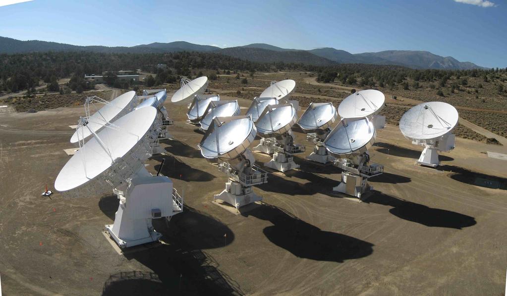
3 Figure 1: The CARMA 23-element interferometer at Cedar Flat. 3
4 1 INTRODUCTION Astronomical studies require observations wide range of spatial scales. 10 m antenna at λ 1.3 mm has a field of view of 30. Extended sources require interferometer and single dish observations. Homogeneous arrays well studied (Cornwell, Holdaway & Uson, 1993). Image fidelity limited by pointing, and primary beam errors. Mosaic observations sample spatial frequencies around each (u, v) point. (Ekers and Rots 1979) Homogeneous array depends heavily on single dish for spatial frequencies less than the antenna diameter. 4
5 2 CARMA Heterogeneous array of 10.4, 6.1, and 3.5 m antennas. OVRO, BIMA and SZA antennas merged on a new site at 2200 m. λ mm aperture synthesis telescope. High spatial dynamic range: 3.5 m to 2 km. 10 arcmin to 0.15 arcsec resolution over a wide field of view. Receiver bands: 26-36, , and GHz. 8 GHz bandwidth in multiple subarrays. 5
6 Figure 2: The OVRO array of 10m antennas. 6

7 Figure 3: The BIMA array of 6m antennas. 7
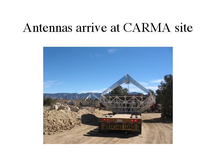
8 Figure 4: Moving 6m antennas from Hat Creek. 8
9 9
10 10

11 Figure 7: Re-building 6m antennas at CARMA 11
12 12

13 Figure 9: Moving 10m antennas 13 thro the narrows to CARMA

14 Figure 10: Re-building 10m antennas at CARMA 14

15 Figure 11: Building CARMA 15
16 Figure 12: E-configuration 16

17 Figure 13: M51 mosaic image combining 151 pointings of the CARMA 15-antenna array. (Koda etal, 2009, ApJ L700, 132) 17
18 3 HETEROGENEOUS ARRAY Adding 3.5 m antennas: Better sensitivity to large scale structures; Sample short uv spacings. Large range of spatial frequencies with interferometer observations. Decouple the source from the primary beam illumination. Cross calibration of 3.5, 6.1 and 10.4 m antennas, for single dish and interferometer observations. Density of uv samples doubled; improves image fidelity. Heterogeneous array produces better image fidelity than homogeneous array with the same number of antennas and collecting area. By historical accident, CARMA has about the right ratio of antenna sizes to produce good image fidelity for mosaics. 18
19 4 DATA SAMPLING Cross correlation of 10.4, 6.1 and 3.5 m antennas provides uv data to deconvolve the synthesized and primary beam responses from the image. Sample rates are set by both the largest and smallest antenna diameter. Nyquist interval for the pointings, δθ = λ/2d max. Nyquist interval for the uv data, δuv = D min /2λ. Data are properly weighted in the imaging algorithms. 10 m antennas on longest interferometer baselines provides more uniform sensitivity and reduces the uv sample rate. This mode produces the best image fidelity in practice. 19
20 5 PRIMARY BEAM PATTERNS Primary beam pattern for each pair of antenna types. Same pointing pattern for all antennas reduces number of primary beam types and minimizes primary beam errors. Mosaic observations with 10.4, 6.1 and 3.5 m antennas produce 6 primary beam types at each pointing center. Primary beam is the product of voltage patterns for each antenna pair. Complex valued PB if voltage patterns are not identical. Errors in voltage beam patterns degrade the image fidelity. 20
21 Table 1: CARMA-23 at 230 GHz Antennas Equivalent diameter FWHM Nyquist interval Gain Thermal noise m x m m arcsec arcsec Jy/K mjy 10.4 x x x x x x Table 1 lists the equivalent antenna diameter, primary beam FWHM and Nyquist sample interval at 230 GHz. Within 5% level, primary beam patterns are Gaussian. Clip primary beam model at 5% to avoid errors at low levels. For best image fidelity use measured voltage patterns for each antenna. 21
22 6 HETEROGENEOUS ARRAY MOSAICING SIMULATIONS Simulated observations with cross correlations between 3.5, 6.1, and 10.4 m antennas. 23-antenna configurations: EZ, DZ, CZ. Model image of Saturn + rings 45 diameter. uv data sampled from -2 to +2 hours: good azimuthal uv coverage, and minimize antenna shadowing. Hexagonal pointing pattern with 15 spacing; 45 diameter source lies within FWHM of 6.1 and 3.5 m antennas. Large field mapped by 3.5 m antennas helps define extent of source. Thermal noise, using receiver temperature 80 K and zenith opacity 0.26 at 230 GHz, was added to the uv data. 22
23 Maximum Entropy (MEM) deconvolution Three different MEM deconvolutions were used: i) Using interferometer data only with a total flux constraint. ii) Using single dish data as a default image. iii) Joint deconvolution of interferometer and single dish data. Resulting images were compared with model to measure image fidelity. 23

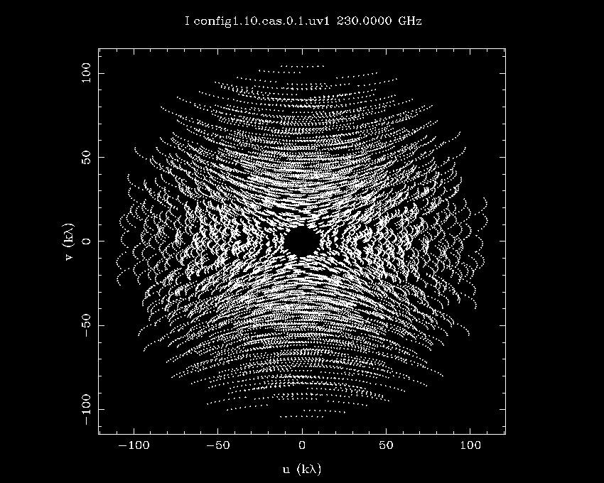
24 Figure 14: CARMA 23-element heterogeneous array. Left: uv data sampling at 100 GHz, DEC=30. Yellow points: uv coverage for the CARMA 15-element array; blue points show the additional uv coverage when the 3.5-m antennas are used in the 23-element array. The dense uv sampling at short spacings shown in the inset, gives sensitivity to larger scale structure. 24 Right: Simulated CARMA observations of Saturn show the increase in image fidelity for extended sources provided by the 3.5 m antennas.
25 7 SINGLE DISH DATA Using single dish data as a default image, provides a total flux estimate and low spatial frequencies unsampled by the interferometric mosaic. This gives higher image fidelity than just using the interferometer data with a total flux estimate. Best image fidelity using joint deconvolution of interferometer and single dish data. Extent to which single dish data can be deconvolved is limited by primary beam and pointing errors in the single dish data. Single dish data from 10.4 m antennas; noise 1% of the peak flux density, to include primary beam and pointing errors. Multiple 10.4 m antennas reduce pointing and primary beam errors. 25
26 Giving higher weight to the single dish data, as in the joint deconvolution, improves the image fidelity, but a 1% error may be unrealistic. In practice, primary beam and pointing errors will limit image fidelity (Cornwell, Holdaway & Uson, 1993). Best image fidelity using cross correlations with 3.5 m antennas. 26
27 8 PRIMARY BEAM ERRORS Heterogeneous cross correlations provides additional uv data to deconvolve the synthesized and primary beam responses from images. Errors in the voltage beam patterns which lie within the primary beam of smaller antennas corrupt images. If we do not determine the primary beam patterns well enough, the errors will degrade the image fidelity. Concentric pointing centers minimize uncertainties in the product of voltage patterns. Asymmetric primary beam patterns rotate on the sky. 27
28 9 USING MEASURED PRIMARY BEAM PATTERNS Primary beam pattern is complex valued if the antenna voltage patterns are not identical. Use measured voltage patterns to generate primary beam patterns for each antenna pair. Simulate mosaic observations using images of Cas A and Saturn scaled to different diameters as source models. Model uv data for ALMA, ACA, ATA and CARMA telescopes. Standard MIRIAD software. 28
29 29
30 30
31 31
32 Image fidelity calculated from difference between mosaic image and original image model convolved to the same resolution. Pointing and primary beam errors cause amplitude and phase errors in the uv data by changing the illumination pattern of the source. Pointing errors corrected on line during data acquisition. Measured deviations in primary beam patterns not well represented by pointing and focus errors. 32
33 Real part of primary beam is close to the canonical Gaussian model. Imaginary part shows an asymmetric gradient caused by offset aperture illumination on some 10 m antennas. Image fidelity increased significantly by correcting this offset. Instrumental polarization response across the primary beam is also improved by reducing the imaginary part of the primary beam response. 33
34 34
35 35
36 36
37 10 PRIMARY BEAM CORRECTION We present a method for deconvolving the primary beam response from interferometric images of astronomical sources. Measured 1-5% deviations from canonical beam patterns can be devastating, reducing image fidelity from 8000 to 50 for a source which fills the primary beam FWHM. The image fidelity is greatly improved by using the measured voltage patterns in the deconvolution. The data are imaged using canonical primary beam patterns, and deconvolved using the measured primary beam voltage patterns. The primary beam may be time variable, non axi-symmetric and different for each antenna. 37
38 Subtract a model image from uv data weighted by the measured primary beam patterns (MIRIAD:uvmodel). Residual uv data are re-imaged to make an improved model image. Iterate until the residual uv data are consistent with thermal noise and other residual instrumental errors. 38
39 11 PAIRED ANTENNA CALIBRATION SYSTEM 3.5 m antennas paired with 6.1 and 10.4 m antennas making science observations at λ mm. 3.5 m antennas simultaneously observe calibration sources at λ 1 cm. Wide field of view of the 3.5 m antennas allows us to find strong calibration sources within 1-3 degrees of the target source. 3.5 m antennas placed within 20 m of 6.1 and 10.4 m antennas so that the atmospheric phase fluctuations are correlated. Subtract the phase fluctuations at λ 1 cm measured by 3.5 m antennas, scaled by frequency, to correct atmospheric phase on the target source. PACS allows us to make images at 0.15 arcec resolution in a wide range of atmospheric seeing conditions. The PACS results are discussed elsewhere in these SPIE proceedings. 39
40 Figure 21: Paired Antenna Calibration System using 3.5 m antennas at 30 GHz. The 3.5 m antennas are paired with 6.1 and 10.4m antennas making science observations at millimeter wavelengths. The 3.5 m antennas simultaneously observe calibration sources in the 1 cm band. For calibration sources within a few degrees, the millimeter wavelength observations of the science40target source, and the observations of the calibrator at 1cm, sample similar atmospheric phase fluctuations, allowing us to correct for the atmospheric phase fluctuations on long baselines at millimeter wavelengths.
41 SZA x 7.5 CARMA CARMA CORRECTED CARMA 2 5 and SZA Calibrator 3C111 during 1mm Science Track Phase (degrees) Time (seconds) Figure 22: Phase correction using Paired Antenna Calibration System. The thick (green) line plots the phase versus time measured between CARMA antennas 2 and 5 while observing the radio source 3C111 at 225 GHz. The large phase fluctuations are caused by atmospheric turbulence on the long baseline between antennas 2 and 5. The dashed (blue) line plots the phase between two 3.5 m antennas which are close to CARMA antennas 2 and 5, but observing at 30 GHz. The 30 GHz phase multiplied by 7.5 (225/30), closely follows the 225 GHz phase allowing us to correct the 225 GHz phase. The thin (red) line shows the 225 GHz phase, corrected for atmospheric phase fluctuations. 41
42 42
43 43
44 44
45 45
46 46
47 12 DISCUSSION Heterogeneous arrays have some advantages: Smaller antennas allow a larger range of spatial frequencies to be sampled by interferometer observations. Heterogeneous beam patterns decouple the source brightness distribution from the primary beam illumination. Short uv spacings; less dependence on single dish observations. Large overlap in spatial frequencies to cross calibrate single dish and interferometer observations. Excellent cross calibration of the 3.5, 6.1 and 10.4 m antennas. 47
48 The 3.5 m antennas effectively sample a guard band around the source brightness distribution. This helps the mosaic algorithms to define the extent of the source. Imaging a guard band without having to make observations at extra pointing centers was an unexpected bonus. Pointing and primary beam errors cause amplitude and phase errors in the measured uv data by changing the illumination pattern of the source. Complex valued primary beam results in polarization errors. Instrumental polarization across the primary beam is significantly improved by reducing the imaginary part of the primary beam which arises from asymmetries in the aperture illumination. 48
49 Image fidelity improved by using the measured voltage patterns in the deconvolution. i) subtract the best estimate of the sky brightness distribution weighted by the measured primary beam pattern from uv data. ii) residual uv data re-imaged to provide an improved model of the sky. iii) iterate until the residual uv data consist of thermal noise and other instrumental errors. These results are relevant to all aperture synthesis arrays, including λ mm/submm arrays like ALMA, and cm/m wavelength arrays like SKA. The results are especially relevant for aperture arrays where the primary beam is time variable. 49
50 At millimeter wavelengths, the voltage patterns can be measured using strong astronomical sources, or a transmitter to obtain sufficient signal to noise. If the primary beam voltage patterns can be characterized as a function of elevation, temperature etc, then these data can be used to correct the uv data. At cm/m wavelengths, the sky brightness model itself may provide the best voltage patterns measurements. The problem is a self-calibration determining sky brightness and primary beam models which are consistent with the uv data in the sense that when the final model of the sky brightness, weighted by the primary beam patterns is subtracted, the residual uv data are consistent with thermal noise or other residual errors. (e.g. LOFAR calibration) 50
51 Alignment of antenna surface, subreflectors, and receiver feeds, feed leg blockage and reflections on the antenna structure all contribute to offsets and asymetries in the aperture illumination. The magnitude and stability of these alignments will determine how well we can correct the data for primary beam characteristics. For phased array station beams, geometric projection and atmospheric path fluctuations make the complex valued station beams time variable. Even for clean voltage patterns with low level sidelobes, the complex sidelobe patterns vary with time due to pointing errors, which cause a time varying illumination of the sky brightness distribution. 51
52 13 CONCLUSIONS Primary beam errors are present in all aperture synthesis arrays and limit the image fidelity. At some level all arrays are heterogeneous. Primary beam and pointing errors dominate the image errors in mosaic observations of large sources. Precision antennas with stable primary beam patterns require fewer parameters which must be determined to calibrate the data. 52
53 53
54 54
55 55
56 Figure 31: Radial distribution of the Fourier transform of Saturn Images. The solid black line shows the Saturn model. The amplitude shows a characteristic Bessel function from the disk and ring system. The red dashed line plots the Fourier transform of the MEM image, before convolving by a restoring beam. The radial distribution is plotted over the range of uv spacings sampled by the CDZ configuration. The lower two curves show the difference images between the MEM images and the original model image both convolved by the restoring beam. 56

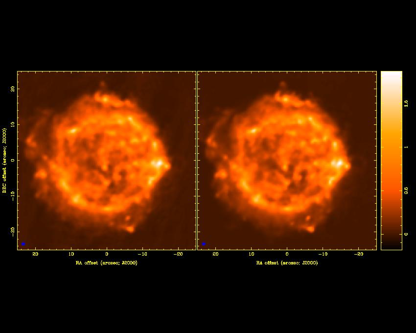
57 Figure 32: Mosaic Image of Cas A model scaled to 128 diameter observed with the CARMA 15-antenna D configuration using a single pointing center at an observing frequency 100 GHz. The grey scale pixel image shows the maximum 57 entropy deconvolution using the three standard truncated Gaussian primary beam models for 10m-10m 10m-6m and 6m-6m antenna pairs. The contours show the residual image when the measured voltage patterns for just one antenna pair, antennas 1 and 8, is used instead of the truncated Gaussian model. Contour intervals: -.004,-.003,-.002,-.001,.001,.002,.003,.004
58 14 REFERENCES Cornwell, T.J., Holdaway, M.A. & Uson, J.M., 1993, Radio-interferometric imaging of very large objects: implications for array design, A&A 271, 697. Ekers, R. D., & Rots, A.H. 1979, in IAU Col. 49, Image Formation from Coherence Functions in Astronomy, ed. van Schooneveld, C. (Dordrecht:Reidel), p.61 Holdaway, M. A., 1998, Mosaicing with Interferometer Arrays, in Synthesis Imaging in Radio Astronomy II, ASP Conference Series, G. B. Taylor, C. L. Carilli and R. A. Perley (Eds) Nijboer, R. J., Noordam, J. E., 2005, LOFAR Calibration, Astronomical Data Analysis Software and Systems XVI ASP Conference Series, Vol. 376, 237, Richard A. Shaw, Frank Hill and David J. Bell. (Eds) Nijboer, R. J., Noordam, J. E., Yatawatta, S. B., 2006, LOFAR Self- 58
59 Calibration using a Local Sky Model, Astronomical Data Analysis Software and Systems XV ASP Conference Series, Vol. 351, 291, Carlos Gabriel, Christophe Arviset, Daniel Ponz, and Enrique Solano. (Eds) Wright, M. C. H. & Corder, S., 2008, SKA memo 103, Deconvolving Primary Beam Patterns from SKA Images 59
Imaging Simulations with CARMA-23
 BIMA memo 101 - July 2004 Imaging Simulations with CARMA-23 M. C. H. Wright Radio Astronomy laboratory, University of California, Berkeley, CA, 94720 ABSTRACT We simulated imaging for the 23-antenna CARMA
Large-field imaging. Frédéric Gueth, IRAM Grenoble. 7th IRAM Millimeter Interferometry School 4 8 October 2010
 Large-field imaging Frédéric Gueth, IRAM Grenoble 7th IRAM Millimeter Interferometry School 4 8 October 2010 Large-field imaging The problems The field of view is limited by the antenna primary beam width
Introduction to Imaging in CASA
 Introduction to Imaging in CASA Mark Rawlings, Juergen Ott (NRAO) Atacama Large Millimeter/submillimeter Array Expanded Very Large Array Robert C. Byrd Green Bank Telescope Very Long Baseline Array Overview
A model for the SKA. Melvyn Wright. Radio Astronomy laboratory, University of California, Berkeley, CA, ABSTRACT
 SKA memo 16. 21 March 2002 A model for the SKA Melvyn Wright Radio Astronomy laboratory, University of California, Berkeley, CA, 94720 ABSTRACT This memo reviews the strawman design for the SKA telescope.
ALMA Memo #289 Atmospheric Noise in Single Dish Observations Melvyn Wright Radio Astronomy Laboratory, University of California, Berkeley 29 February
 ALMA Memo #289 Atmospheric Noise in Single Dish Observations Melvyn Wright Radio Astronomy Laboratory, University of California, Berkeley 29 February 2000 Abstract Atmospheric noise and pointing fluctuations
Phased Array Feeds A new technology for multi-beam radio astronomy
 Phased Array Feeds A new technology for multi-beam radio astronomy Aidan Hotan ASKAP Deputy Project Scientist 2 nd October 2015 CSIRO ASTRONOMY AND SPACE SCIENCE Outline Review of radio astronomy concepts.
Real Time Imaging. Melvyn Wright. Radio Astronomy Laboratory, University of California, Berkeley, CA, ABSTRACT
 SKA MEMO 60, 24 May 2005 Real Time Imaging Melvyn Wright Radio Astronomy Laboratory, University of California, Berkeley, CA, 94720 ABSTRACT In this paper, we propose to integrate the imaging process with
Plan for Imaging Algorithm Research and Development
 Plan for Imaging Algorithm Research and Development S. Bhatnagar July 05, 2009 Abstract Many scientific deliverables of the next generation radio telescopes require wide-field imaging or high dynamic range
Antennas. Greg Taylor. University of New Mexico Spring Astronomy 423 at UNM Radio Astronomy
 Antennas Greg Taylor University of New Mexico Spring 2017 Astronomy 423 at UNM Radio Astronomy Outline 2 Fourier Transforms Interferometer block diagram Antenna fundamentals Types of antennas Antenna performance
arxiv: v1 [astro-ph.im] 23 Sep 2013
![arxiv: v1 [astro-ph.im] 23 Sep 2013](/thumbs/72/66796347.jpg "arxiv: v1 [astro-ph.im] 23 Sep 2013") CADRE: The CArma Data REduction pipeline D. N. Friedel a arxiv:1309.5844v1 [astro-ph.im] 23 Sep 2013 a University of Illinois, Department of Astronomy, 1002 W. Green St., Urbana, IL 61801 Abstract The
CADRE: The CArma Data REduction pipeline D. N. Friedel a arxiv:1309.5844v1 [astro-ph.im] 23 Sep 2013 a University of Illinois, Department of Astronomy, 1002 W. Green St., Urbana, IL 61801 Abstract The
Deconvolution. Amy Mioduszewski National Radio Astronomy Observatory. Synthesis Imaging g in Radio Astronomy
 Deconvolution Amy Mioduszewski National Radio Astronomy Observatory Synthesis Imaging g in Radio Astronomy (based on a talk given by David Wilner (CfA) at the NRAO s 2010 Synthesis Imaging Workshop) 1
ALMA Phase Calibration, Phase Correction and the Water Vapour Radiometers
 ALMA Phase Calibration, Phase Correction and the Water Vapour Radiometers B. Nikolic 1, J. S. Richer 1, R. E. Hills 1,2 1 MRAO, Cavendish Lab., University of Cambridge 2 Joint ALMA Office, Santiago, Chile
ASTRO 6525 Lecture #18:! (Sub-)Millimeter Interferometry I!! October 27, 2015!
Millimeter Interferometry I!! October 27, 2015!") ASTRO 6525 Lecture #18:! (Sub-)Millimeter Interferometry I!! October 27, 2015! Dominik A. Riechers Find me at office SSB 220 E-mail: dr@astro.cornell.edu Schedule for this Section Today: Introduction to
ASTRO 6525 Lecture #18:! (Sub-)Millimeter Interferometry I!! October 27, 2015! Dominik A. Riechers Find me at office SSB 220 E-mail: dr@astro.cornell.edu Schedule for this Section Today: Introduction to
Phased Array Feeds A new technology for wide-field radio astronomy
 Phased Array Feeds A new technology for wide-field radio astronomy Aidan Hotan ASKAP Project Scientist 29 th September 2017 CSIRO ASTRONOMY AND SPACE SCIENCE Outline Review of radio astronomy concepts
Wide-Band Imaging. Outline : CASS Radio Astronomy School Sept 2012 Narrabri, NSW, Australia. - What is wideband imaging?
 Wide-Band Imaging 24-28 Sept 2012 Narrabri, NSW, Australia Outline : - What is wideband imaging? - Two Algorithms Urvashi Rau - Many Examples National Radio Astronomy Observatory Socorro, NM, USA 1/32
ATCA Antenna Beam Patterns and Aperture Illumination
 1 AT 39.3/116 ATCA Antenna Beam Patterns and Aperture Illumination Jared Cole and Ravi Subrahmanyan July 2002 Detailed here is a method and results from measurements of the beam characteristics of the
Radio Astronomy: SKA-Era Interferometry and Other Challenges. Dr Jasper Horrell, SKA SA (and Dr Oleg Smirnov, Rhodes and SKA SA)
") Radio Astronomy: SKA-Era Interferometry and Other Challenges Dr Jasper Horrell, SKA SA (and Dr Oleg Smirnov, Rhodes and SKA SA) ASSA Symposium, Cape Town, Oct 2012 Scope SKA antenna types Single dishes
Radio Astronomy: SKA-Era Interferometry and Other Challenges Dr Jasper Horrell, SKA SA (and Dr Oleg Smirnov, Rhodes and SKA SA) ASSA Symposium, Cape Town, Oct 2012 Scope SKA antenna types Single dishes
Mosaicking. Brian Mason (NRAO) Sixteenth Synthesis Imaging Workshop May 2018
 Sixteenth Synthesis Imaging Workshop May 2018") Mosaicking Brian Mason (NRAO) Sixteenth Synthesis Imaging Workshop 16-23 May 2018 The simplest observing scenario for an interferometer: Source at known location Size
Mosaicking Brian Mason (NRAO) Sixteenth Synthesis Imaging Workshop 16-23 May 2018 The simplest observing scenario for an interferometer: Source at known location Size
Introduction to Radio Interferometry Sabrina Stierwalt Alison Peck, Jim Braatz, Ashley Bemis
 Introduction to Radio Interferometry Sabrina Stierwalt Alison Peck, Jim Braatz, Ashley Bemis Atacama Large Millimeter/submillimeter Array Expanded Very Large Array Robert C. Byrd Green Bank Telescope Very
Antennas. Greg Taylor. University of New Mexico Spring Astronomy 423 at UNM Radio Astronomy
 Antennas Greg Taylor University of New Mexico Spring 2011 Astronomy 423 at UNM Radio Astronomy Radio Window 2 spans a wide range of λ and ν from λ ~ 0.33 mm to ~ 20 m! (ν = 1300 GHz to 15 MHz ) Outline
Spectral Line II: Calibration and Analysis. Spectral Bandpass: Bandpass Calibration (cont d) Bandpass Calibration. Bandpass Calibration
 Bandpass Calibration. Bandpass Calibration") Spectral Line II: Calibration and Analysis Bandpass Calibration Flagging Continuum Subtraction Imaging Visualization Analysis Spectral Bandpass: Spectral frequency response of antenna to a spectrally flat
Spectral Line II: Calibration and Analysis Bandpass Calibration Flagging Continuum Subtraction Imaging Visualization Analysis Spectral Bandpass: Spectral frequency response of antenna to a spectrally flat
Components of Imaging at Low Frequencies: Status & Challenges
 Components of Imaging at Low Frequencies: Status & Challenges Dec. 12th 2013 S. Bhatnagar NRAO Collaborators: T.J. Cornwell, R. Nityananda, K. Golap, U. Rau J. Uson, R. Perley, F. Owen Telescope sensitivity
arxiv:astro-ph/ v1 21 Jun 2006
 Ð Ú Ø ÓÒ Ò Ð Ô Ò Ò Ó Ø ËÅ ÒØ ÒÒ ÓÙ ÔÓ Ø ÓÒ Satoki Matsushita a,c, Masao Saito b,c, Kazushi Sakamoto b,c, Todd R. Hunter c, Nimesh A. Patel c, Tirupati K. Sridharan c, and Robert W. Wilson c a Academia
Radio Interferometer Array Point Spread Functions I. Theory and Statistics
 ALMA MEMO 389 Radio Interferometer Array Point Spread Functions I. Theory and Statistics David Woody Abstract This paper relates the optical definition of the PSF to radio interferometer arrays. The statistical
EVLA and LWA Imaging Challenges
 EVLA and LWA Imaging Challenges Steven T. Myers IGPP, Los Alamos National Laboratory and National Radio Astronomy Observatory, Socorro, NM 1 EVLA key issues 2 Key algorithmic issues ambitious goals / hard
Technical Considerations: Nuts and Bolts Project Planning and Technical Justification
 Technical Considerations: Nuts and Bolts Project Planning and Technical Justification Atacama Large Millimeter/submillimeter Array Expanded Very Large Array Robert C. Byrd Green Bank Telescope Very Long
Introduction to Interferometry. Michelson Interferometer. Fourier Transforms. Optics: holes in a mask. Two ways of understanding interferometry
 Introduction to Interferometry P.J.Diamond MERLIN/VLBI National Facility Jodrell Bank Observatory University of Manchester ERIS: 5 Sept 005 Aim to lay the groundwork for following talks Discuss: General
OPTICS OF SINGLE BEAM, DUAL BEAM & ARRAY RECEIVERS ON LARGE TELESCOPES J A M E S W L A M B, C A L T E C H
 OPTICS OF SINGLE BEAM, DUAL BEAM & ARRAY RECEIVERS ON LARGE TELESCOPES J A M E S W L A M B, C A L T E C H OUTLINE Antenna optics Aberrations Diffraction Single feeds Types of feed Bandwidth Imaging feeds
EVLA Scientific Commissioning and Antenna Performance Test Check List
 EVLA Scientific Commissioning and Antenna Performance Test Check List C. J. Chandler, C. L. Carilli, R. Perley, October 17, 2005 The following requirements come from Chapter 2 of the EVLA Project Book.
Phased Array Feeds & Primary Beams
 Phased Array Feeds & Primary Beams Aidan Hotan ASKAP Deputy Project Scientist 3 rd October 2014 CSIRO ASTRONOMY AND SPACE SCIENCE Outline Review of parabolic (dish) antennas. Focal plane response to a
Sideband Smear: Sideband Separation with the ALMA 2SB and DSB Total Power Receivers
 and DSB Total Power Receivers SCI-00.00.00.00-001-A-PLA Version: A 2007-06-11 Prepared By: Organization Date Anthony J. Remijan NRAO A. Wootten T. Hunter J.M. Payne D.T. Emerson P.R. Jewell R.N. Martin
INTERFEROMETRY: II Nissim Kanekar (NCRA TIFR)
") INTERFEROMETRY: II Nissim Kanekar (NCRA TIFR) WSRT GMRT VLA ATCA ALMA SKA MID PLAN Introduction. The van Cittert Zernike theorem. A 2 element interferometer. The fringe pattern. 2 D and 3 D interferometers.
INTERFEROMETRY: II Nissim Kanekar (NCRA TIFR) WSRT GMRT VLA ATCA ALMA SKA MID PLAN Introduction. The van Cittert Zernike theorem. A 2 element interferometer. The fringe pattern. 2 D and 3 D interferometers.
Cross Correlators. Jayce Dowell/Greg Taylor. University of New Mexico Spring Astronomy 423 at UNM Radio Astronomy
 Cross Correlators Jayce Dowell/Greg Taylor University of New Mexico Spring 2017 Astronomy 423 at UNM Radio Astronomy Outline 2 Re-cap of interferometry What is a correlator? The correlation function Simple
EVLA System Commissioning Results
 EVLA System Commissioning Results EVLA Advisory Committee Meeting, March 19-20, 2009 Rick Perley EVLA Project Scientist t 1 Project Requirements EVLA Project Book, Chapter 2, contains the EVLA Project
Wide Bandwidth Imaging
 Wide Bandwidth Imaging 14th NRAO Synthesis Imaging Workshop 13 20 May, 2014, Socorro, NM Urvashi Rau National Radio Astronomy Observatory 1 Why do we need wide bandwidths? Broad-band receivers => Increased
Introduction to Radio Interferometry Anand Crossley Alison Peck, Jim Braatz, Ashley Bemis (NRAO)
") Introduction to Radio Interferometry Anand Crossley Alison Peck, Jim Braatz, Ashley Bemis (NRAO) Atacama Large Millimeter/submillimeter Array Expanded Very Large Array Robert C. Byrd Green Bank Telescope
Introduction to Radio Interferometry Anand Crossley Alison Peck, Jim Braatz, Ashley Bemis (NRAO) Atacama Large Millimeter/submillimeter Array Expanded Very Large Array Robert C. Byrd Green Bank Telescope
Basic Mapping Simon Garrington JBO/Manchester
 Basic Mapping Simon Garrington JBO/Manchester Introduction Output from radio arrays (VLA, VLBI, MERLIN etc) is just a table of the correlation (amp. & phase) measured on each baseline every few seconds.
Fundamentals of Interferometry
 Fundamentals of Interferometry ERIS, Rimini, Sept 5-9 2011 Outline What is an interferometer? Basic theory Interlude: Fourier transforms for birdwatchers Review of assumptions and complications Interferometers
Memo 65 SKA Signal processing costs
 Memo 65 SKA Signal processing costs John Bunton, CSIRO ICT Centre 12/08/05 www.skatelescope.org/pages/page_memos.htm Introduction The delay in the building of the SKA has a significant impact on the signal
REDUCTION OF ALMA DATA USING CASA SOFTWARE
 REDUCTION OF ALMA DATA USING CASA SOFTWARE Student: Nguyen Tran Hoang Supervisor: Pham Tuan Anh Hanoi, September - 2016 1 CONTENS Introduction Interferometry Scientific Target M100 Calibration Imaging
Pointing Calibration Steps
 ALMA-90.03.00.00-00x-A-SPE 2007 08 02 Specification Document Jeff Mangum & Robert The Man Lucas Page 2 Change Record Revision Date Author Section/ Remarks Page affected 1 2003-10-10 Jeff Mangum All Initial
A Crash Course in Radio Astronomy and Interferometry: 1. Basic Radio/mm Astronomy
 A Crash Course in Radio Astronomy and Interferometry: 1. Basic Radio/mm Astronomy James Di Francesco National Research Council of Canada North American ALMA Regional Center Victoria (thanks to S. Dougherty,
SMA Technical Memo 147 : 08 Sep 2002 HOLOGRAPHIC SURFACE QUALITY MEASUREMENTS OF THE SUBMILLIMETER ARRAY ANTENNAS
 SMA Technical Memo 147 : 08 Sep 2002 HOLOGRAPHIC SURFACE QUALITY MEASUREMENTS OF THE SUBMILLIMETER ARRAY ANTENNAS T. K. Sridharan, M. Saito, N. A. Patel Harvard-Smithsonian Center for Astrophysics 60 Garden
Towards SKA Multi-beam concepts and technology
 Towards SKA Multi-beam concepts and technology SKA meeting Meudon Observatory, 16 June 2009 Philippe Picard Station de Radioastronomie de Nançay philippe.picard@obs-nancay.fr 1 Square Kilometre Array:
Array Configuration for the Long Wavelength Intermediate Array (LWIA): Choosing the First Four Station Sites
: Choosing the First Four Station Sites") Array Configuration for the Long Wavelength Intermediate Array (LWIA): Choosing the First Four Station Sites Aaron Cohen (NRL) and Greg Taylor (UNM) December 4, 2007 ABSTRACT The Long Wavelength Intermediate
Array Configuration for the Long Wavelength Intermediate Array (LWIA): Choosing the First Four Station Sites Aaron Cohen (NRL) and Greg Taylor (UNM) December 4, 2007 ABSTRACT The Long Wavelength Intermediate
Commissioning Report for the ATCA L/S Receiver Upgrade Project
 Commissioning Report for the ATCA L/S Receiver Upgrade Project N. M. McClure-Griffiths, J. B. Stevens, & S. P. O Sullivan 8 June 211 1 Introduction The original Australia Telescope Compact Array (ATCA)
ARRAY DESIGN AND SIMULATIONS
 ARRAY DESIGN AND SIMULATIONS Craig Walker NRAO Based in part on 2008 lecture by Aaron Cohen TALK OUTLINE STEPS TO DESIGN AN ARRAY Clarify the science case Determine the technical requirements for the key
Spectral Line Observing
 Spectral Line Observing Ylva Pihlström, UNM Eleventh Synthesis Imaging Workshop Socorro, June 10-17, 2008 Introduction 2 Spectral line observers use many channels of width δν, over a total bandwidth Δν.
Very Long Baseline Interferometry
 Very Long Baseline Interferometry Cormac Reynolds, JIVE European Radio Interferometry School, Bonn 12 Sept. 2007 VLBI Arrays EVN (Europe, China, South Africa, Arecibo) VLBA (USA) EVN + VLBA coordinate
Fundamentals of Radio Interferometry
 Fundamentals of Radio Interferometry Rick Perley, NRAO/Socorro Fourteenth NRAO Synthesis Imaging Summer School Socorro, NM Topics Why Interferometry? The Single Dish as an interferometer The Basic Interferometer
Introduction to Millimeter Wavelength Interferometry
 CARMA SUMMER SCHOOL - June 2008 Introduction to Millimeter Wavelength Interferometry Melvyn Wright Radio Astronomy Laboratory, University of California, Berkeley, CA, 94720 Contents 1 INTRODUCTION 5 1.1
Comparing MMA and VLA Capabilities in the GHz Band. Socorro, NM Abstract
 Comparing MMA and VLA Capabilities in the 36-50 GHz Band M.A. Holdaway National Radio Astronomy Observatory Socorro, NM 87801 September 29, 1995 Abstract I explore the capabilities of the MMA and the VLA,
Calibration Issues for the MMA
 MMA Project Book, Chapter 3: Calibration Calibration Issues for the MMA Mark Holdaway Last modified 1998-Jul-22 Revised by Al Wootten Last changed 1998-Nov-11 Revision History: 1998-Nov-03:Format modified
Adaptive selective sidelobe canceller beamformer with applications in radio astronomy
 Adaptive selective sidelobe canceller beamformer with applications in radio astronomy Ronny Levanda and Amir Leshem 1 Abstract arxiv:1008.5066v1 [astro-ph.im] 30 Aug 2010 We propose a new algorithm, for
Why Single Dish? Why Single Dish? Darrel Emerson NRAO Tucson
 Why Single Dish? Darrel Emerson NRAO Tucson Why Single Dish? What's the Alternative? Comparisons between Single-Dish, Phased Array & Interferometers Advantages and Disadvantages of Correlation Interferometer
Next Generation Very Large Array Memo No. 16 More on Synthesized Beams and Sensitivity. C.L. Carilli, NRAO, PO Box O, Socorro, NM
 Next Generation Very Large Array Memo No. 16 More on Synthesized Beams and Sensitivity C.L. Carilli, NRAO, PO Box O, Socorro, NM Abstract I present further calculations on synthesized beams and sensitivities
High Fidelity Imaging of Extended Sources. Rick Perley NRAO Socorro, NM
 High Fidelity Imaging of Extended Sources Rick Perley NRAO Socorro, NM A Brief History of Calibration (VLA) An Amazing Fact: The VLA was proposed, and funded, without any real concept of how to calibrate
LOFAR: Special Issues
 Netherlands Institute for Radio Astronomy LOFAR: Special Issues John McKean (ASTRON) ASTRON is part of the Netherlands Organisation for Scientific Research (NWO) 1 Preamble http://www.astron.nl/~mckean/eris-2011-2.pdf
SKA1 low Baseline Design: Lowest Frequency Aspects & EoR Science
 SKA1 low Baseline Design: Lowest Frequency Aspects & EoR Science 1 st science Assessment WS, Jodrell Bank P. Dewdney Mar 27, 2013 Intent of the Baseline Design Basic architecture: 3-telescope, 2-system
Error Recognition Emil Lenc (and Arin)
") Error Recognition Emil Lenc (and Arin) University of Sydney / CAASTRO www.caastro.org CASS Radio Astronomy School 2017 Based on lectures given previously by Ron Ekers and Steven Tingay CSIRO; Swinburne
Error Recognition Emil Lenc (and Arin) University of Sydney / CAASTRO www.caastro.org CASS Radio Astronomy School 2017 Based on lectures given previously by Ron Ekers and Steven Tingay CSIRO; Swinburne
Antennas & Receivers in Radio Astronomy
 Antennas & Receivers in Radio Astronomy Mark McKinnon Fifteenth Synthesis Imaging Workshop 1-8 June 2016 Purpose & Outline Purpose: describe how antenna elements can affect the quality of images produced
The 4mm (68-92 GHz) Receiver
 Receiver") Chapter 18 The 4mm (68-92 GHz) Receiver 18.1 Overview The 4 mm receiver ( W-band ) is a dual-beam, dual-polarization receiver which covers the frequency range of approximately 67-93 GHz. The performance
Chapter 18 The 4mm (68-92 GHz) Receiver 18.1 Overview The 4 mm receiver ( W-band ) is a dual-beam, dual-polarization receiver which covers the frequency range of approximately 67-93 GHz. The performance
Fundamentals of Radio Interferometry
 Fundamentals of Radio Interferometry Rick Perley, NRAO/Socorro 15 th Synthesis Imaging School Socorro, NM 01 09 June, 2016 Topics The Need for Interferometry Some Basics: Antennas as E-field Converters
The Antenna Configuration of the Allen Telescope Array
 ATA memo 50 The Antenna Configuration of the Allen Telescope Array Douglas Bock Radio Astronomy Laboratory, University of California at Berkeley January 8, 2003 ABSTRACT This memo describes the antenna
Atacama Large Millimeter/submillimeter Array Expanded Very Large Array Robert C. Byrd Green Bank Telescope Very Long Baseline Array
 Atacama Large Millimeter/submillimeter Array Expanded Very Large Array Robert C. Byrd Green Bank Telescope Very Long Baseline Array Basics of Interferometry Data Reduction Scott Schnee (NRAO) ALMA Data
Volume 82 VERY LONG BASELINE INTERFEROMETRY AND THE VLBA. J. A. Zensus, P. J. Diamond, and P. J. Napier
 ASTRONOMICAL SOCIETY OF THE PACIFIC CONFERENCE SERIES Volume 82 VERY LONG BASELINE INTERFEROMETRY AND THE VLBA Proceedings of a Summer School held in Socorro, New Mexico 23-30 June 1993 NRAO Workshop No.
Review of WVRs in Astronomy
 Review of WVRs in Astronomy (Wiedner) Alan Roy MPIfR The Troposphere as Seen from Orbit Method: Synthetic Aperture Radar (Earth Resources Satellite) Frequency: 9 GHz Region: Groningen Interferograms by
Recent progress in EVLA-specific algorithms. EVLA Advisory Committee Meeting, March 19-20, S. Bhatnagar and U. Rau
 Recent progress in EVLA-specific algorithms EVLA Advisory Committee Meeting, March 19-20, 2009 S. Bhatnagar and U. Rau Imaging issues Full beam, full bandwidth, full Stokes noise limited imaging Algorithmic
EVLA Memo 105. Phase coherence of the EVLA radio telescope
 EVLA Memo 105 Phase coherence of the EVLA radio telescope Steven Durand, James Jackson, and Keith Morris National Radio Astronomy Observatory, 1003 Lopezville Road, Socorro, NM, USA 87801 ABSTRACT The
Fundamentals of Radio Interferometry. Robert Laing (ESO)
") Fundamentals of Radio Interferometry Robert Laing (ESO) 1 ERIS 2015 Objectives A more formal approach to radio interferometry using coherence functions A complementary way of looking at the technique Simplifying
Fundamentals of Radio Interferometry Robert Laing (ESO) 1 ERIS 2015 Objectives A more formal approach to radio interferometry using coherence functions A complementary way of looking at the technique Simplifying
Imaging and Calibration Algorithms for EVLA, e-merlin and ALMA. Robert Laing ESO
 Imaging and Calibration Algorithms for EVLA, e-merlin and ALMA Socorro, April 3 2008 Workshop details Oxford, 2008 Dec 1-3 Sponsored by Radionet and the University of Oxford 56 participants http://astrowiki.physics.ox.ac.uk/cgi-bin/twiki/view/algorithms2008/webhome
More Radio Astronomy
 More Radio Astronomy Radio Telescopes - Basic Design A radio telescope is composed of: - a radio reflector (the dish) - an antenna referred to as the feed on to which the radiation is focused - a radio
Principles of Radio Interferometry. Ast735: Submillimeter Astronomy IfA, University of Hawaii
 Principles of Radio Interferometry Ast735: Submillimeter Astronomy IfA, University of Hawaii 1 Resources IRAM millimeter interferometry school hdp://www.iram- inshtute.org/en/content- page- 248-7- 67-248-
Parameterized Deconvolution for Wide-Band Radio Synthesis Imaging
 Parameterized Deconvolution for Wide-Band Radio Synthesis Imaging Urvashi Rao Venkata Ph.D. Thesis Defense Department of Physics, New Mexico Institute of Mining and Technology 17 May 2010 Advisors / Committee
Next Generation Very Large Array Memo No. 47 Resolution and Sensitivity of ngvla-revb. C.L. Carilli (NRAO)
") Next Generation Very Large Array Memo No. 47 Resolution and Sensitivity of ngvla-revb C.L. Carilli (NRAO) Abstract I investigate the noise performance vs. resolution for the new ngvlarevb configuration.
Next Generation Very Large Array Memo No. 47 Resolution and Sensitivity of ngvla-revb C.L. Carilli (NRAO) Abstract I investigate the noise performance vs. resolution for the new ngvlarevb configuration.
The Basics of Radio Interferometry. Frédéric Boone LERMA, Observatoire de Paris
 The Basics of Radio Interferometry LERMA, Observatoire de Paris The Basics of Radio Interferometry The role of interferometry in astronomy = role of venetian blinds in Film Noir 2 The Basics of Radio Interferometry
Introduction to Radio Astronomy!
 Introduction to Radio Astronomy! Sources of radio emission! Radio telescopes - collecting the radiation! Processing the radio signal! Radio telescope characteristics! Observing radio sources Sources of
To print higher-resolution math symbols, click the Hi-Res Fonts for Printing button on the jsmath control panel.
 To print higher-resolution math symbols, click the Hi-Res Fonts for Printing button on the jsmath control panel. Radiometers Natural radio emission from the cosmic microwave background, discrete astronomical
Receiver Performance and Comparison of Incoherent (bolometer) and Coherent (receiver) detection
 and Coherent (receiver) detection") At ev gap /h the photons have sufficient energy to break the Cooper pairs and the SIS performance degrades. Receiver Performance and Comparison of Incoherent (bolometer) and Coherent (receiver) detection
At ev gap /h the photons have sufficient energy to break the Cooper pairs and the SIS performance degrades. Receiver Performance and Comparison of Incoherent (bolometer) and Coherent (receiver) detection
Final Feed Selection Study For the Multi Beam Array System
 National Astronomy and Ionosphere Center Arecibo Observatory Focal Array Memo Series Final Feed Selection Study For the Multi Beam Array System By: Germán Cortés-Medellín CORNELL July/19/2002 U n i v e
Fundamentals of Interferometry
 Fundamentals of Interferometry ERIS, Dwingeloo, Sept 8-13 2013 Outline What is an interferometer? Basic theory Interlude: Fourier transforms for birdwatchers Review of assumptions and complications Interferometers
ASD and Speckle Interferometry. Dave Rowe, CTO, PlaneWave Instruments
 ASD and Speckle Interferometry Dave Rowe, CTO, PlaneWave Instruments Part 1: Modeling the Astronomical Image Static Dynamic Stochastic Start with Object, add Diffraction and Telescope Aberrations add Atmospheric
Multiplying Interferometers
 Multiplying Interferometers L1 * L2 T + iv R1 * R2 T - iv L1 * R2 Q + iu R1 * L2 Q - iu Since each antenna can output both L and R polarization, all 4 Stokes parameters are simultaneously measured without
Overview of the SKA. P. Dewdney International SKA Project Engineer Nov 9, 2009
 Overview of the SKA P. Dewdney International SKA Project Engineer Nov 9, 2009 Outline* 1. SKA Science Drivers. 2. The SKA System. 3. SKA technologies. 4. Trade-off space. 5. Scaling. 6. Data Rates & Data
Fundamentals of Radio Interferometry
 Fundamentals of Radio Interferometry Rick Perley, NRAO/Socorro ATNF Radio Astronomy School Narrabri, NSW 29 Sept. 03 Oct. 2014 Topics Introduction: Sensors, Antennas, Brightness, Power Quasi-Monochromatic
Planning ALMA Observations
 Planning Observations Atacama Large mm/sub-mm Array Mark Lacy North American Science Center Atacama Large Millimeter/submillimeter Array Expanded Very Large Array Robert C. Byrd Green Bank Telescope Very
CARMA Memorandum Series #14 1
 CARMA Memorandum Series #14 1 Stability of BIMA antenna position solutions J. R. Forster Hat Creek Observatory, University of California, Berkeley, CA, 94720 September 25, 2003 ABSTRACT We review the stability
Smart Antennas in Radio Astronomy
 Smart Antennas in Radio Astronomy Wim van Cappellen cappellen@astron.nl Netherlands Institute for Radio Astronomy Our mission is to make radio-astronomical discoveries happen ASTRON is an institute for
ALMA Sensitivity Metric for Science Sustainability Projects
 ALMA Memo 602 ALMA Sensitivity Metric for Science Sustainability ALMA-35.00.101.666-A-SPE 2017 01 23 Description Document Jeff Mangum (NRAO) Page 2 Change Record Revision Date Author Section/ Remarks Page
How small can you get? reducing data volume, retaining good imaging
 How small can you get? reducing data volume, retaining good imaging Anita Richards UK ALMA Regional Centre Jodrell Bank Centre for Astrophysics University of Manchester thanks to Crystal Brogan and all
Fourier Transforms in Radio Astronomy
 Fourier Transforms in Radio Astronomy Kavilan Moodley, UKZN Slides taken from N Gupta s lectures: SKA School 2013 van-cittert Zernike theorem Extended, quasi-monochromatic, incoherent source X (l,m) Y
THEORY OF MEASUREMENTS
 THEORY OF MEASUREMENTS Brian Mason Fifth NAIC-NRAO School on Single-Dish Radio Astronomy Arecibo, PR July 2009 OUTLINE Antenna-Sky Coupling Noise the Radiometer Equation Minimum Tsys Performance measures
Chapter 41 Deep Space Station 13: Venus
 Chapter 41 Deep Space Station 13: Venus The Venus site began operation in Goldstone, California, in 1962 as the Deep Space Network (DSN) research and development (R&D) station and is named for its first
LOFAR: From raw visibilities to calibrated data
 Netherlands Institute for Radio Astronomy LOFAR: From raw visibilities to calibrated data John McKean (ASTRON) [subbing in for Manu] ASTRON is part of the Netherlands Organisation for Scientific Research
Chalmers Publication Library
 Chalmers Publication Library Analysis of the strut and feed blockage effects in radio telescopes with compact UWB feeds This document has been downloaded from Chalmers Publication Library (CPL). It is
Radio Interferometers Around the World. Amy J. Mioduszewski (NRAO)
") Radio Interferometers Around the World Amy J. Mioduszewski (NRAO) A somewhat biased view of current interferometers Limited to telescopes that exist or are in the process of being built (i.e., I am not
Radio Interferometers Around the World Amy J. Mioduszewski (NRAO) A somewhat biased view of current interferometers Limited to telescopes that exist or are in the process of being built (i.e., I am not
THE VLA LOW-FREQUENCY SKY SURVEY
 The Astronomical Journal, 134:1245 Y 1262, 2007 September # 2007. The American Astronomical Society. All rights reserved. Printed in U.S.A. THE VLA LOW-FREQUENCY SKY SURVEY A. S. Cohen, 1 W. M. Lane, 1
Introduction to Radio Astronomy. Richard Porcas Max-Planck-Institut fuer Radioastronomie, Bonn
 Introduction to Radio Astronomy Richard Porcas Max-Planck-Institut fuer Radioastronomie, Bonn 1 Contents Radio Waves Radio Emission Processes Radio Noise Radio source names and catalogues Radio telescopes
Radio Data Archives. how to find, retrieve, and image radio data: a lay-person s primer. Michael P Rupen (NRAO)
") Radio Data Archives how to find, retrieve, and image radio data: a lay-person s primer Michael P Rupen (NRAO) By the end of this talk, you should know: The standard radio imaging surveys that provide FITS
Radio Data Archives how to find, retrieve, and image radio data: a lay-person s primer Michael P Rupen (NRAO) By the end of this talk, you should know: The standard radio imaging surveys that provide FITS
Introduction to Millimeter Wavelength Interferometry
 CARMA SUMMER SCHOOL - July 2007 Introduction to Millimeter Wavelength Interferometry Melvyn Wright Radio Astronomy Laboratory, University of California, Berkeley, CA, 94720 1. OUTLINE Day 1: Basic introduction