Radio Interferometry -- II
|
|
|
- Vincent Bates
- 6 years ago
- Views:
Transcription


1 Radio Interferometry -- II Rick Perley, NRAO/Socorro 15 th Synthesis Imaging Summer School June 1 9, 2016 Socorro, NM
2 Topics Practical Extensions to the Theory: Real Sensors Finite bandwidth Rotating reference frames (source motion) Finite time averaging Local Oscillators and Frequency Downconversion Coordinate systems Direction cosines 2-D ( planar ) interferometers 3-D ( volume ) interferometers U-V Coverage, Visibilities, and Simple Structures.
3 Review In the previous lecture, I set down the principles of Fourier synthesis imaging. I showed: Where the intensity I n is a real function, and the visibility V(b) is complex and Hermitian. The model used for the derivation was idealistic not met in practice: Idealized Sensors Monochromatic Stationary reference frame. RF throughout We now relax, in turn, these restrictions.
4 Real Sensors I developed the integral relationship presuming idealized sensors uniform sensitivity in all directions. Such a device doesn t exist. Real sensors (antennas) have a directional voltage gain pattern A(s, s 0 ), where s is a general direction, and s 0 is a pointing direction. The gain pattern is (nominally) easily incorporated into the formalism, once we realize that it attenuates the actual sky brightness. We can write: Here, A 1 and A 2 are the normalized complex voltage attenuation functions for the two antennas. Note that if the antennas are identical, and pointing in the same direction, then A 1 A 2 = P, the normalized power response.
. They get increasingly out of step as n gets larger.")
5 Effect of Finite Bandwidth A baseline has a fixed physical length, B. But the fringe pattern depends on its length in wavelengths. Each slice of wavelength has a pattern with angular separation of ~ l/b. Each component has a maximum at the n=0 fringe (meridional plane). They get increasingly out of step as n gets larger. A simple illustration three wavelength components from the same physical baseline. The net result is the sum over all components. Here, this is shown in the thick blue line.
 With more components (nine equal ones in this case), the summed")
6 Bandwidth Effect (cont.) With more components (nine equal ones in this case), the summed response begins to look like a wave packet.


7 The Effect of Bandwidth -- Analysis. To find the finite-bandwidth response, we integrate our fundamental response over a frequency response G(n), of width Dn, centered at n 0 : If the source intensity does not vary over the bandwidth, and the instrumental gain parameters G 1 and G 2 are square and identical, then where the fringe attenuation function, sinc(x), is defined as:

8 Bandwidth Effect Example For a square bandpass, the bandwidth attenuation reaches a null when t g Dn = 1, or c sin l / B D / B D n For the old VLA, and its 50 MHz bandwidth, and for the A configuration, the null was only ~ 35 arcseconds away. For the JanskyVLA, Dn = 1 MHz, and B = 35 km, then the null occurs at about 30 arcminutes off the meridian. 0 Fringe Attenuation function: Number of fringes between peak and null: c sin B Dn N ~ c B D B l ~ D
9 Observations off the Meridian In our basic scenario -- stationary source, stationary interferometer -- the effect of finite bandwidth will strongly attenuate the fringe amplitudes from sources far from the meridional plane. Since each baseline has its own plane, the only point on the sky free of attenuation for all baselines is a small angle around the zenith (presuming all baselines are coplanar). Suppose we wish to observe an object far from the zenith? Best way is to shift the entire fringe packet to the position of interest by adding time delay to the antenna closer to the source.

 direction S =")


10 Adding Time Delay t 0 s 0 s s 0 t g b s A sensor S 0 = reference (delay) direction S = general direction X t 0 The entire fringe pattern has been shifted over by angle sin = ct 0 /b
11 Illustrating Delay Tracking Top Panel: Delay has been added and subtracted to move the delay pattern to the source location. Bottom Panel: A cosinusoidal sensor pattern is added, to illustrate losses from a fixed sensor.
12 Observations from a Rotating Platform Real interferometers are built on the surface of the earth a rotating platform. From the observer s perspective, sources move across the sky. Since we know how to adjust the interferometer timing to move its coherence pattern to the direction of interest, it is a simple step to continuously move the pattern to follow a moving source. All that is necessary is to continuously add time delay, with an accuracy dt << 1/Dn to minimize bandwidth loss. But there s one more issue to keep in mind
13 Phase Tracking Adding time delay will prevent bandwidth losses for observations off the baseline s meridian. But between delay settings, the source is moving through the interferometer pattern a rapidly changing phase. How fast? The natural fringe rate due to earth s rotation, is given by f u w e cos d Where u = B/l, the (E-W) baseline in wavelengths, and w e =7.3x10⁻⁵ rad/s is the angular rotation rate of the earth. For a million-wavelength baseline, n f ~ 70 Hz that s fast. If we leave things this way, we have to sample the output at at least twice this rate. A lot of data! Hz
14 Following a Moving Object. There is *no* useful information in this fringe rate it s simply a manifestation of the platform rotation. Tracking, or stopping the fringes greatly slows down the *post-correlation* data processing/archiving needs. To stop the fringes, we must adjust the phase in one path. How fast: Tracking delay: Tracking phase: d f B D c B w l The rates given are appropriate for 35 km baselines, 128 MHz bandwidth, and 3 cm wavelength. For the RF interferometer, delay insertion does both. e w cos e cos d ~ d 70 ~ 1 Hz Hz
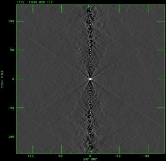
15 Emphasis: Shown again is the fringe pattern of a real wideband baseline. To preserve the visibility amplitude, we must re-set delays before source moves too far down the pattern. To maintain a stable phase, we must reset ~n/dn times faster. Source moves this way
16 Time Averaging Loss So we can track a moving source, continuously adjusting the delay to move the fringe pattern with the source. This does two good things: Slows down the data recording needs Prevents bandwidth delay losses. From this, you might think that you can increase the time averaging for as long as you please. But you can t because stopping the fringes only works for the object in the center the point for which the delays and phases have been pre-set. All other sources are moving w.r.t. the fringe pattern and this is where the essential information lies

17 Time-Smearing Loss Timescale Simple derivation of fringe period, from observation at the NCP. NCP w e l/d Source Turquoise area is antenna primary beam on the sky radius = l/d Interferometer coherence pattern has spacing = l/b Sources in sky rotate about NCP at angular rate: w e =7.3x10⁻⁵ rad/sec. Minimum time taken for a source to move by l/b at angular distance is: Interferometer Fringe Separation l/b Primary Beam This is 10 seconds for a 35- Half Power kilometer baseline and a For sources at the primary beam null

18 Illustrating Time Averaging Loss An object located away from the fringe tracking center moves through the pattern as the earth rotates. It makes one cycle around in 24 hours. If we average the correlation products for too long a period, a loss in fringe amplitude will result. Illustrating time average loss. Blue trace: the fringe amplitude with no averaging. Red trace: Amplitude after averaging for 12 samples.
19 Time-Averaging Loss So, what kind of time-scales are we talking about now? How long can you integrate before the differential motion destroys the fringe amplitude? Case A: A 25-meter parabaloid, and 35-km baseline: t = D/(Bw e ) = 10 seconds. (independent of observing frequency). Case B: Whole Hemisphere for a 35-km baseline: t = l/(bw e ) sec = 83 msec at 21 cm. Averaging for durations longer than these will cause severe attenuation of the visibility amplitudes. To prevent delay losses, your averaging time must be much less than this. Averaging time 1/10 of this value normally sufficient to prevent time loss.
20 The Heterodyne Interferometer: LOs, IFs, and Downcoversion This would be the end of the story (so far as the fundamentals are concerned) if all the internal electronics of an interferometer would work at the observing frequency (often called the radio frequency, or RF). Unfortunately, this cannot be done in general, as high frequency components are much more expensive, and generally perform more poorly than low frequency components. Thus, most radio interferometers use down-conversion to translate the radio frequency information from the RF to a lower frequency band, called the IF in the jargon of our trade. For signals in the radio-frequency part of the spectrum, this can be done with almost no loss of information. But there is an important side-effect from this operation in interferometry which we now review.
21 Downconversion At radio frequencies, the spectral content within a passband can be shifted with almost no loss in information, to a lower frequency through multiplication by a LO signal. Sensor LO RF In X IF Out Filter Filtered IF Out P(n) P(n) P(n) n n n Original Spectrum n LO Lower and Upper Sidebands, plus LO Lower Sideband Only This operation preserves the amplitude and phase relations.
22 Signal Relations, with LO Downconversion The RF signals are multiplied by a pure sinusoid, at frequency n LO We can add arbitrary phase f LO on one side. t g X w LO f LO Local Oscillator (w RF =w LO +w IF ) Phase Shifter Complex Correlator X t 0 E cos(w RF t) Multiplier E cos(w IF t-f LO ) E cos(w IF t-w RF t g ) X E cos(w IF t-w IF t 0 -f LO ) Not the same phase as the RF interferometer!

23 Recovering the Correct Visibility Phase The correct phase (RF interferometer) is: w t - RF g t 0 The observed phase (with frequency downconversion) is: w t - - w t IF 0 These will be the same when the LO phase is set to: RF g f LO This is necessary because the delay, t 0, has been added in the IF portion of the signal path, rather than at the frequency at which the delay actually occurs. The phase adjustment of the LO compensates for the delay having been inserted at the IF, rather than at the RF.
24 The Three Centers in Interferometry You are forgiven if you re confused by all these centers. So let s review: 1. Beam Tracking (Pointing) Center: Where the antennas are pointing to. (Or, for phased arrays, the phased array center position). 2. Delay Tracking Center: The location for which the delays are being set for maximum wide-band coherence. 3. Phase Tracking Center: The location for which the LO phase is slipping in order to track the coherence pattern. Note: Generally, we make all three the same. #2 and #3 are the same for an RF interferometer. They are separable in a LO downconversion system.
25 Interferometer Geometry We have not defined any geometric system for our relations. The response functions we defined were generalized in terms of the scalar product between two fundamental vectors: The baseline B, defining the direction and separation of the antennas, and The unit vector s, specifying the direction of the source. At this time, we define the geometric coordinate frame for the interferometer. We begin with a special case: An interferometer whose antennas all lie on a single plane.
26 The 2-Dimensional Interferometer To give better understanding, we now specify the geometry. Case A: A 2-dimensional measurement plane. Let us imagine the measurements of V n (b) to be taken entirely on a plane. Then a considerable simplification occurs if we arrange the coordinate system so one axis is normal to this plane. Let (u,v,w) be the coordinate axes, with w normal to this plane. Then: u, v, and w are always measured in wavelengths. The components of the unit direction vector, s, are:
27 The (u,v,w) Coordinate System. Pick a coordinate system (u,v,w) to describe the antenna positions and baselines. Orient this frame so the plane containing the antennas lies on w = 0. The baseline vector b is specified by its coordinates (u,v,w) (measured in wavelengths). In the case shown, w = 0, and b ( lu, lv,0) u w b b v

28 Direction Cosines describing the source The unit direction vector s is defined by its projections (l,m,n) on the (u,v,w) axes. These components are called the Direction Cosines. l n a w b m s v b u The angles, a, b, and are between the direction vector and the three axes.
: And we can now rely on two")
29 The 2-d Fourier Transform Relation Then, nb.s/c = ul + vm + wn = ul + vm, from which we find, which is a 2-dimensional Fourier transform between the brightness and the spatial coherence function (visibility): And we can now rely on two centuries of effort by mathematicians on how to invert this equation, and how much information we need to obtain an image of sufficient quality. Formally, In physical optics, this is known as the Van Cittert-Zernicke Theorem.
30 Interferometers with 2-d Geometry Which interferometers can use this special geometry? a) Those whose baselines, over time, lie on a plane (any plane). All E-W interferometers are in this group. For these, the w-coordinate points to the NCP. WSRT (Westerbork Synthesis Radio Telescope) ATCA (Australia Telescope Compact Array) (before the third arm) Cambridge 5km (Ryle) telescope (almost). b) Any coplanar 2-dimensional array, at a single instance of time. In this case, the w coordinate points to the zenith. VLA or GMRT in snapshot (single short observation) mode. What's the downside of 2-d (u,v) coverage? Resolution degrades for observations that are not in the w-direction. E-W interferometers have no N-S resolution for observations at the celestial equator. A VLA snapshot of a source will have no vertical resolution for objects on the horizon.
31 Generalized Baseline Geometry Coplanar arrays (like the VLA) cannot use the 2-d geometry, since the plane of the array is rotating w.r.t. the source. In this case, we adopt a more general geometry, where all three baseline components are to be considered. l n a w b m s v b u
32 General Coordinate System This is the coordinate system in most general use for synthesis imaging. w points to, and follows the source, u towards the east, and v towards the north celestial pole. The direction cosines l and m then increase to the east and north, respectively. Projected Baseline u 2 v 2 v w s 0 b s 0 u-v plane always perpendicular to direction to the source.
33 3-d Interferometers Case B: A 3-dimensional measurement volume: What if the interferometer does not measure the coherence function on a plane, but rather does it through a volume? In this case, we adopt a different coordinate system. First we write out the full expression: (Note that this is not a 3-D Fourier Transform). We orient the w-axis of the coordinate system to point to the region of interest. The u-axis point east, and the v-axis to the north celestial pole. We introduce phase tracking, so the fringes are stopped for the i w direction l=m=0. This means we adjust the phases by e Then, remembering that we get: n 1 - l - m

34 3-d to 2-d The expression is still not a proper Fourier transform. We can get a 2-d FT if the third term in the phase factor is sufficient small. The third term in the phase can be neglected if it is much less than unity: This condition holds when: (angles in radians!) If this condition is met, then the relation between the Intensity and the Visibility again becomes a 2-dimensional Fourier transform:
35 The Problem with Non-coplanar Baselines Use of the 2-D transform for non-coplanar interferometer arrays (like the VLA, when used over time) always results in an error in the images. The Clark Condition for trouble is: Hence, the problem is most acute for small-diameter antennas (D small) long baselines (B large), and long wavelengths (l large) The problems are not in the principles, but in the cost of the solutions. Full 3-D imaging works, but isn t cheap. Implemented solutions include faceted imaging, and W- Projection. l B D 2 1
 Y points")

36 Rotation Axis Coverage of the U-V Plane Obtaining a good image of a source requires adequate sampling ( coverage ) of the (u,v) plane. Adopt an earth-based coordinate grid to describe the antenna positions: X points to H=0, d=0 (intersection of meridian and celestial equator) Y points to H = -6, d = 0 (to east, on celestial equator) Z points to d = 90 (to NCP). Equator NP Z X Thus, Bx, By are the baseline components in the Equatorial plane, Bz is the baseline component along the earth s rotation axis. All components in wavelengths. d 0 and H 0 are the declination and right ascension of the phase center.


37 (u,v,w) Coordinates Then, it can be shown that The u and v coordinates describe E-W and N-S components of the projected interferometer baseline. The w coordinate is the delay distance in wavelengths between the two antennas. The geometric delay, t g is given by Its derivative, called the fringe frequency n F is


38 E-W Array Coverage and Beams The simplest case is for E-W arrays, which give coplanar coverage. Then, Bx = Bz = 0 Consider a minimum redundancy array, with eight antennas located at 0, 1, 2, 11, 15, 18, 21 and 23 km along an E-W arm. o o o o o o o o Of the 28 simultaneous spacings, 23 are of a unique separation. The U-V coverage (over 12 hours) at d = 90, and the synthesized beam are shown below, for a wavelength of 1m.


39 E-W Arrays and Low-Dec sources. But the trouble with E-W arrays is that they are not suited for low-declination observing. At d=0, coverage degenerates to a line. d 60 d 30 d 10
 E-W baselines (Bx = Bz = 0) have no v offset in the ellipses.")
40 Baseline Locus the General Case Each baseline, over 24 hours, traces out an ellipse in the (u,v) plane: Because brightness is real, each observation provides us a second point, where: V(-u,-v) = V*(u,v) E-W baselines (Bx = Bz = 0) have no v offset in the ellipses. V A single Visibility: V(u,v) Its Complex Conjugate V(-u,-v) 2 2 B B X Y B Z cosd 0 U Good UV Coverage requires many simultaneous baselines amongst many antennas, or many sequential baselines from a few antennas.
41 Getting Good Coverage near d = 0 The only means of getting good 2-d angular resolution at all declinations is to build an array with N-S spacings. Many more antennas are needed to provide good coverage for such geometries. The VLA was designed to do this, using 9 antennas on each of three equiangular arms. Built in the 1970s, commissioned in 1980, the VLA vastly improved radio synthesis imaging at all declinations. Each of the 351 spacings traces an elliptical locus on the (u,v) plane. Every baseline has some (N-S) component, so none of the ellipses is centered on the origin.
. HA = -2h HA = 0h HA = 2h Coverage over all four hours.")
42 Sample VLA (U,V) plots for 3C147 (d = 50) Snapshot (u,v) coverage for HA = -2, 0, +2 (with 26 antennas). HA = -2h HA = 0h HA = 2h Coverage over all four hours.


43 VLA Coverage and Beams d=90 d=60 d=30 d=0 d=-30 Good coverage at all declinations, but troubles near d=0 remain.
44 UV Coverage and Imaging Fidelity Although the VLA represented a huge advance over what came before, its UV coverage (and imaging fidelity) is far from optimal. The high density of samplings along the arms (the 6-armed star in snapshot coverage) results in rays in the images due to small errors. A better design is to randomize the location of antennas within the span of the array, to better distribute the errors. Of course, more antennas would really help! :). The VLA s wye design was dictated by its 220 ton antennas, and the need to move them. Railway tracks were the only answer. Future major arrays will utilize smaller, lighter elements which must not be positioned with any regularity.
Practicalities of Radio Interferometry
 Practicalities of Radio Interferometry Rick Perley, NRAO/Socorro 13 th Synthesis Imaging Summer School 29 May 5 June, 2012 Socorro, NM Topics Practical Extensions to the Theory: Finite bandwidth Rotating
Radio Interferometry -- II
 Radio Interferometry -- II Rick Perley, NRAO/Socorro ATNF School on Radio Astronomy Narrabri, NSW 29 Sept 3 Oct, 2014 Topics Practical Extensions to the Theory: Finite bandwidth Rotating reference frames
Practicalities of Radio Interferometry
 Practicalities of Radio Interferometry Rick Perley, NRAO/Socorro Fourth INPE Course in Astrophysics: Radio Astronomy in the 21 st Century Topics Practical Extensions to the Theory: Finite bandwidth Rotating
Fundamentals of Radio Interferometry
 Fundamentals of Radio Interferometry Rick Perley, NRAO/Socorro Fourteenth NRAO Synthesis Imaging Summer School Socorro, NM Topics Why Interferometry? The Single Dish as an interferometer The Basic Interferometer
Fundamentals of Radio Interferometry
 Fundamentals of Radio Interferometry Rick Perley, NRAO/Socorro ATNF Radio Astronomy School Narrabri, NSW 29 Sept. 03 Oct. 2014 Topics Introduction: Sensors, Antennas, Brightness, Power Quasi-Monochromatic
Fundamentals of Radio Interferometry
 Fundamentals of Radio Interferometry Rick Perley, NRAO/Socorro 15 th Synthesis Imaging School Socorro, NM 01 09 June, 2016 Topics The Need for Interferometry Some Basics: Antennas as E-field Converters
INTERFEROMETRY: II Nissim Kanekar (NCRA TIFR)
") INTERFEROMETRY: II Nissim Kanekar (NCRA TIFR) WSRT GMRT VLA ATCA ALMA SKA MID PLAN Introduction. The van Cittert Zernike theorem. A 2 element interferometer. The fringe pattern. 2 D and 3 D interferometers.
INTERFEROMETRY: II Nissim Kanekar (NCRA TIFR) WSRT GMRT VLA ATCA ALMA SKA MID PLAN Introduction. The van Cittert Zernike theorem. A 2 element interferometer. The fringe pattern. 2 D and 3 D interferometers.
Interferometry I Parkes Radio School Jamie Stevens ATCA Senior Systems Scientist
 Interferometry I Parkes Radio School 2011 Jamie Stevens ATCA Senior Systems Scientist 2011-09-28 References This talk will reuse material from many previous Radio School talks, and from the excellent textbook
Introduction to Interferometry. Michelson Interferometer. Fourier Transforms. Optics: holes in a mask. Two ways of understanding interferometry
 Introduction to Interferometry P.J.Diamond MERLIN/VLBI National Facility Jodrell Bank Observatory University of Manchester ERIS: 5 Sept 005 Aim to lay the groundwork for following talks Discuss: General
Synthesis Imaging Theory
 Synthesis Imaging Theory Tony Foley tony@hartrao.ac.za Why interferometry? For this, diffraction theory applies the angular resolution for a wavelength λ is : Θ λ/d In practical units: To obtain 1 arcsecond
Fundamentals of Radio Interferometry
 Fundamentals of Radio Interferometry Rick Perley, NRAO/Socorro Green Bank Interferometry School NRAO/GB 12 14 July, 2015 Topics The Need for Interferometry Some Basics: Antennas as E-field Converters Conceptual
Fundamentals of Interferometry
 Fundamentals of Interferometry ERIS, Rimini, Sept 5-9 2011 Outline What is an interferometer? Basic theory Interlude: Fourier transforms for birdwatchers Review of assumptions and complications Interferometers
The Basics of Radio Interferometry. Frédéric Boone LERMA, Observatoire de Paris
 The Basics of Radio Interferometry LERMA, Observatoire de Paris The Basics of Radio Interferometry The role of interferometry in astronomy = role of venetian blinds in Film Noir 2 The Basics of Radio Interferometry
Fourier Transforms in Radio Astronomy
 Fourier Transforms in Radio Astronomy Kavilan Moodley, UKZN Slides taken from N Gupta s lectures: SKA School 2013 van-cittert Zernike theorem Extended, quasi-monochromatic, incoherent source X (l,m) Y
High Fidelity Imaging of Extended Sources. Rick Perley NRAO Socorro, NM
 High Fidelity Imaging of Extended Sources Rick Perley NRAO Socorro, NM A Brief History of Calibration (VLA) An Amazing Fact: The VLA was proposed, and funded, without any real concept of how to calibrate
Fundamentals of Interferometry
 Fundamentals of Interferometry ERIS, Dwingeloo, Sept 8-13 2013 Outline What is an interferometer? Basic theory Interlude: Fourier transforms for birdwatchers Review of assumptions and complications Interferometers
Random Phase Antenna Combining for SETI SETICon03
 Random Phase Antenna Combining for SETI SETICon03 Marko Cebokli S57UUU ABSTRACT: Since the direction from which the first ETI signal will arrive is not known in advance, it is possible to relax the phasing
Sideband Smear: Sideband Separation with the ALMA 2SB and DSB Total Power Receivers
 and DSB Total Power Receivers SCI-00.00.00.00-001-A-PLA Version: A 2007-06-11 Prepared By: Organization Date Anthony J. Remijan NRAO A. Wootten T. Hunter J.M. Payne D.T. Emerson P.R. Jewell R.N. Martin
Phased Array Feeds & Primary Beams
 Phased Array Feeds & Primary Beams Aidan Hotan ASKAP Deputy Project Scientist 3 rd October 2014 CSIRO ASTRONOMY AND SPACE SCIENCE Outline Review of parabolic (dish) antennas. Focal plane response to a
Propagation effects (tropospheric and ionospheric phase calibration)
") Propagation effects (tropospheric and ionospheric phase calibration) Prof. Steven Tingay Curtin University of Technology Perth, Australia With thanks to Alan Roy (MPIfR), James Anderson (JIVE), Tasso Tzioumis
Propagation effects (tropospheric and ionospheric phase calibration) Prof. Steven Tingay Curtin University of Technology Perth, Australia With thanks to Alan Roy (MPIfR), James Anderson (JIVE), Tasso Tzioumis
More Radio Astronomy
 More Radio Astronomy Radio Telescopes - Basic Design A radio telescope is composed of: - a radio reflector (the dish) - an antenna referred to as the feed on to which the radiation is focused - a radio
Introduction to interferometry with bolometers: Bob Watson and Lucio Piccirillo
 Introduction to interferometry with bolometers: Bob Watson and Lucio Piccirillo Paris, 19 June 2008 Interferometry (heterodyne) In general we have i=1,...,n single dishes (with a single or dual receiver)
DECEMBER 1964 NUMBER OF COPIES: 75
 NATIONAL RADIO ASTRONOMY OBSERVATORY Green Bank, West Virginia E ectronics Division Internal Report No. 42 A DIGITAL CROSS-CORRELATION INTERFEROMETER Nigel J. Keen DECEMBER 964 NUMBER OF COPIES: 75 A DIGITAL
Basic Mapping Simon Garrington JBO/Manchester
 Basic Mapping Simon Garrington JBO/Manchester Introduction Output from radio arrays (VLA, VLBI, MERLIN etc) is just a table of the correlation (amp. & phase) measured on each baseline every few seconds.
Fundamentals of Radio Interferometry. Robert Laing (ESO)
") Fundamentals of Radio Interferometry Robert Laing (ESO) 1 ERIS 2015 Objectives A more formal approach to radio interferometry using coherence functions A complementary way of looking at the technique Simplifying
Fundamentals of Radio Interferometry Robert Laing (ESO) 1 ERIS 2015 Objectives A more formal approach to radio interferometry using coherence functions A complementary way of looking at the technique Simplifying
Principles of Radio Interferometry. Ast735: Submillimeter Astronomy IfA, University of Hawaii
 Principles of Radio Interferometry Ast735: Submillimeter Astronomy IfA, University of Hawaii 1 Resources IRAM millimeter interferometry school hdp://www.iram- inshtute.org/en/content- page- 248-7- 67-248-
Introduction to Radioastronomy: Interferometers and Aperture Synthesis
 Introduction to Radioastronomy: Interferometers and Aperture Synthesis J.Köppen joachim.koppen@astro.unistra.fr http://astro.u-strasbg.fr/~koppen/jkhome.html Problem No.2: Angular resolution Diffraction
Radio Interferometry. Xuening Bai. AST 542 Observational Seminar May 4, 2011
 Radio Interferometry Xuening Bai AST 542 Observational Seminar May 4, 2011 Outline Single-dish radio telescope Two-element interferometer Interferometer arrays and aperture synthesis Very-long base line
EVLA Memo 146 RFI Mitigation in AIPS. The New Task UVRFI
 EVLA Memo 1 RFI Mitigation in AIPS. The New Task UVRFI L. Kogan, F. Owen 1 (1) - National Radio Astronomy Observatory, Socorro, New Mexico, USA June, 1 Abstract Recently Ramana Athrea published a new algorithm
RADIOMETRIC TRACKING. Space Navigation
 RADIOMETRIC TRACKING Space Navigation Space Navigation Elements SC orbit determination Knowledge and prediction of SC position & velocity SC flight path control Firing the attitude control thrusters to
Introduction to Imaging in CASA
 Introduction to Imaging in CASA Mark Rawlings, Juergen Ott (NRAO) Atacama Large Millimeter/submillimeter Array Expanded Very Large Array Robert C. Byrd Green Bank Telescope Very Long Baseline Array Overview
EVLA Memo 105. Phase coherence of the EVLA radio telescope
 EVLA Memo 105 Phase coherence of the EVLA radio telescope Steven Durand, James Jackson, and Keith Morris National Radio Astronomy Observatory, 1003 Lopezville Road, Socorro, NM, USA 87801 ABSTRACT The
Lecture 3 Complex Exponential Signals
 Lecture 3 Complex Exponential Signals Fundamentals of Digital Signal Processing Spring, 2012 Wei-Ta Chu 2012/3/1 1 Review of Complex Numbers Using Euler s famous formula for the complex exponential The
TSBB09 Image Sensors 2018-HT2. Image Formation Part 1
 TSBB09 Image Sensors 2018-HT2 Image Formation Part 1 Basic physics Electromagnetic radiation consists of electromagnetic waves With energy That propagate through space The waves consist of transversal
RECOMMENDATION ITU-R S.1257
 Rec. ITU-R S.157 1 RECOMMENDATION ITU-R S.157 ANALYTICAL METHOD TO CALCULATE VISIBILITY STATISTICS FOR NON-GEOSTATIONARY SATELLITE ORBIT SATELLITES AS SEEN FROM A POINT ON THE EARTH S SURFACE (Questions
Antenna Arrays. EE-4382/ Antenna Engineering
 Antenna Arrays EE-4382/5306 - Antenna Engineering Outline Introduction Two Element Array Rectangular-to-Polar Graphical Solution N-Element Linear Array: Uniform Spacing and Amplitude Theory of N-Element
EVLA Scientific Commissioning and Antenna Performance Test Check List
 EVLA Scientific Commissioning and Antenna Performance Test Check List C. J. Chandler, C. L. Carilli, R. Perley, October 17, 2005 The following requirements come from Chapter 2 of the EVLA Project Book.
Interference [Hecht Ch. 9]
![Interference [Hecht Ch. 9]](/thumbs/79/79365345.jpg "Interference [Hecht Ch. 9]") Interference [Hecht Ch. 9] Note: Read Ch. 3 & 7 E&M Waves and Superposition of Waves and Meet with TAs and/or Dr. Lai if necessary. General Consideration 1 2 Amplitude Splitting Interferometers If a lightwave
Interference [Hecht Ch. 9] Note: Read Ch. 3 & 7 E&M Waves and Superposition of Waves and Meet with TAs and/or Dr. Lai if necessary. General Consideration 1 2 Amplitude Splitting Interferometers If a lightwave
RADIOMETRIC TRACKING. Space Navigation
 RADIOMETRIC TRACKING Space Navigation October 24, 2016 D. Kanipe Space Navigation Elements SC orbit determination Knowledge and prediction of SC position & velocity SC flight path control Firing the attitude
Array Configuration for the Long Wavelength Intermediate Array (LWIA): Choosing the First Four Station Sites
: Choosing the First Four Station Sites") Array Configuration for the Long Wavelength Intermediate Array (LWIA): Choosing the First Four Station Sites Aaron Cohen (NRL) and Greg Taylor (UNM) December 4, 2007 ABSTRACT The Long Wavelength Intermediate
Array Configuration for the Long Wavelength Intermediate Array (LWIA): Choosing the First Four Station Sites Aaron Cohen (NRL) and Greg Taylor (UNM) December 4, 2007 ABSTRACT The Long Wavelength Intermediate
Phased Array Feeds A new technology for multi-beam radio astronomy
 Phased Array Feeds A new technology for multi-beam radio astronomy Aidan Hotan ASKAP Deputy Project Scientist 2 nd October 2015 CSIRO ASTRONOMY AND SPACE SCIENCE Outline Review of radio astronomy concepts.
Very Long Baseline Interferometry
 Very Long Baseline Interferometry Cormac Reynolds, JIVE European Radio Interferometry School, Bonn 12 Sept. 2007 VLBI Arrays EVN (Europe, China, South Africa, Arecibo) VLBA (USA) EVN + VLBA coordinate
Introduction to Radio Interferometry Sabrina Stierwalt Alison Peck, Jim Braatz, Ashley Bemis
 Introduction to Radio Interferometry Sabrina Stierwalt Alison Peck, Jim Braatz, Ashley Bemis Atacama Large Millimeter/submillimeter Array Expanded Very Large Array Robert C. Byrd Green Bank Telescope Very
A model for the SKA. Melvyn Wright. Radio Astronomy laboratory, University of California, Berkeley, CA, ABSTRACT
 SKA memo 16. 21 March 2002 A model for the SKA Melvyn Wright Radio Astronomy laboratory, University of California, Berkeley, CA, 94720 ABSTRACT This memo reviews the strawman design for the SKA telescope.
Radio Data Archives. how to find, retrieve, and image radio data: a lay-person s primer. Michael P Rupen (NRAO)
") Radio Data Archives how to find, retrieve, and image radio data: a lay-person s primer Michael P Rupen (NRAO) By the end of this talk, you should know: The standard radio imaging surveys that provide FITS
Radio Data Archives how to find, retrieve, and image radio data: a lay-person s primer Michael P Rupen (NRAO) By the end of this talk, you should know: The standard radio imaging surveys that provide FITS
Wide-Band Imaging. Outline : CASS Radio Astronomy School Sept 2012 Narrabri, NSW, Australia. - What is wideband imaging?
 Wide-Band Imaging 24-28 Sept 2012 Narrabri, NSW, Australia Outline : - What is wideband imaging? - Two Algorithms Urvashi Rau - Many Examples National Radio Astronomy Observatory Socorro, NM, USA 1/32
Submillimeter (continued)
") Submillimeter (continued) Dual Polarization, Sideband Separating Receiver Dual Mixer Unit The 12-m Receiver Here is where the receiver lives, at the telescope focus Receiver Performance T N (noise temperature)
Submillimeter (continued) Dual Polarization, Sideband Separating Receiver Dual Mixer Unit The 12-m Receiver Here is where the receiver lives, at the telescope focus Receiver Performance T N (noise temperature)
Next Generation Very Large Array Memo No. 16 More on Synthesized Beams and Sensitivity. C.L. Carilli, NRAO, PO Box O, Socorro, NM
 Next Generation Very Large Array Memo No. 16 More on Synthesized Beams and Sensitivity C.L. Carilli, NRAO, PO Box O, Socorro, NM Abstract I present further calculations on synthesized beams and sensitivities
Traveling Wave Antennas
 Traveling Wave Antennas Antennas with open-ended wires where the current must go to zero (dipoles, monopoles, etc.) can be characterized as standing wave antennas or resonant antennas. The current on these
Receiver Performance and Comparison of Incoherent (bolometer) and Coherent (receiver) detection
 and Coherent (receiver) detection") At ev gap /h the photons have sufficient energy to break the Cooper pairs and the SIS performance degrades. Receiver Performance and Comparison of Incoherent (bolometer) and Coherent (receiver) detection
At ev gap /h the photons have sufficient energy to break the Cooper pairs and the SIS performance degrades. Receiver Performance and Comparison of Incoherent (bolometer) and Coherent (receiver) detection
Correlator Development at Haystack. Roger Cappallo Haystack-NRAO Technical Mtg
 Correlator Development at Haystack Roger Cappallo Haystack-NRAO Technical Mtg. 2006.10.26 History of Correlator Development at Haystack ~1973 Mk I 360 Kb/s x 2 stns. 1981 Mk III 112 Mb/s x 4 stns. 1986
Spectral Line Observing
 Spectral Line Observing Ylva Pihlström, UNM Eleventh Synthesis Imaging Workshop Socorro, June 10-17, 2008 Introduction 2 Spectral line observers use many channels of width δν, over a total bandwidth Δν.
Introduction to Radio Interferometry Anand Crossley Alison Peck, Jim Braatz, Ashley Bemis (NRAO)
") Introduction to Radio Interferometry Anand Crossley Alison Peck, Jim Braatz, Ashley Bemis (NRAO) Atacama Large Millimeter/submillimeter Array Expanded Very Large Array Robert C. Byrd Green Bank Telescope
Introduction to Radio Interferometry Anand Crossley Alison Peck, Jim Braatz, Ashley Bemis (NRAO) Atacama Large Millimeter/submillimeter Array Expanded Very Large Array Robert C. Byrd Green Bank Telescope
LOFAR: Special Issues
 Netherlands Institute for Radio Astronomy LOFAR: Special Issues John McKean (ASTRON) ASTRON is part of the Netherlands Organisation for Scientific Research (NWO) 1 Preamble http://www.astron.nl/~mckean/eris-2011-2.pdf
Dr. Martina B. Arndt Physics Department Bridgewater State College (MA) Based on work by Dr. Alan E.E. Rogers MIT s Haystack Observatory (MA)
 Based on work by Dr. Alan E.E. Rogers MIT s Haystack Observatory (MA)") VSRT INTRODUCTION Dr Martina B Arndt Physics Department Bridgewater State College (MA) Based on work by Dr Alan EE Rogers MIT s Haystack Observatory (MA) August, 2009 1 PREFACE The Very Small Radio Telescope
VSRT INTRODUCTION Dr Martina B Arndt Physics Department Bridgewater State College (MA) Based on work by Dr Alan EE Rogers MIT s Haystack Observatory (MA) August, 2009 1 PREFACE The Very Small Radio Telescope
Cross Correlators. Jayce Dowell/Greg Taylor. University of New Mexico Spring Astronomy 423 at UNM Radio Astronomy
 Cross Correlators Jayce Dowell/Greg Taylor University of New Mexico Spring 2017 Astronomy 423 at UNM Radio Astronomy Outline 2 Re-cap of interferometry What is a correlator? The correlation function Simple
The Discrete Fourier Transform. Claudia Feregrino-Uribe, Alicia Morales-Reyes Original material: Dr. René Cumplido
 The Discrete Fourier Transform Claudia Feregrino-Uribe, Alicia Morales-Reyes Original material: Dr. René Cumplido CCC-INAOE Autumn 2015 The Discrete Fourier Transform Fourier analysis is a family of mathematical
Phased Array Feeds A new technology for wide-field radio astronomy
 Phased Array Feeds A new technology for wide-field radio astronomy Aidan Hotan ASKAP Project Scientist 29 th September 2017 CSIRO ASTRONOMY AND SPACE SCIENCE Outline Review of radio astronomy concepts
THE SINUSOIDAL WAVEFORM
 Chapter 11 THE SINUSOIDAL WAVEFORM The sinusoidal waveform or sine wave is the fundamental type of alternating current (ac) and alternating voltage. It is also referred to as a sinusoidal wave or, simply,
EVLA System Commissioning Results
 EVLA System Commissioning Results EVLA Advisory Committee Meeting, March 19-20, 2009 Rick Perley EVLA Project Scientist t 1 Project Requirements EVLA Project Book, Chapter 2, contains the EVLA Project
To print higher-resolution math symbols, click the Hi-Res Fonts for Printing button on the jsmath control panel.
 To print higher-resolution math symbols, click the Hi-Res Fonts for Printing button on the jsmath control panel. Radiometers Natural radio emission from the cosmic microwave background, discrete astronomical
Introduction to Radio Astronomy. Richard Porcas Max-Planck-Institut fuer Radioastronomie, Bonn
 Introduction to Radio Astronomy Richard Porcas Max-Planck-Institut fuer Radioastronomie, Bonn 1 Contents Radio Waves Radio Emission Processes Radio Noise Radio source names and catalogues Radio telescopes
REDUCTION OF ALMA DATA USING CASA SOFTWARE
 REDUCTION OF ALMA DATA USING CASA SOFTWARE Student: Nguyen Tran Hoang Supervisor: Pham Tuan Anh Hanoi, September - 2016 1 CONTENS Introduction Interferometry Scientific Target M100 Calibration Imaging
APRIL 1966 NUMBER OF COPIES: 75
 NATIONAL RADIO ASTRONOMY OBSERVATORY Green Bank, West Virginia Electronics Division Internal Report No. 55 SINGLE SIDEBAND, DOUBLE SIDE BAND, OR MIXED INTERFEROMETER RECEIVERS Karel H. Wesseling APRIL
Lecture 6 Fiber Optical Communication Lecture 6, Slide 1
 Lecture 6 Optical transmitters Photon processes in light matter interaction Lasers Lasing conditions The rate equations CW operation Modulation response Noise Light emitting diodes (LED) Power Modulation
Antennas & Receivers in Radio Astronomy
 Antennas & Receivers in Radio Astronomy Mark McKinnon Fifteenth Synthesis Imaging Workshop 1-8 June 2016 Purpose & Outline Purpose: describe how antenna elements can affect the quality of images produced
speech signal S(n). This involves a transformation of S(n) into another signal or a set of signals
. This involves a transformation of S(n) into another signal or a set of signals") 16 3. SPEECH ANALYSIS 3.1 INTRODUCTION TO SPEECH ANALYSIS Many speech processing [22] applications exploits speech production and perception to accomplish speech analysis. By speech analysis we extract
16 3. SPEECH ANALYSIS 3.1 INTRODUCTION TO SPEECH ANALYSIS Many speech processing [22] applications exploits speech production and perception to accomplish speech analysis. By speech analysis we extract
DRAFT. Enhanced Image Rejection in Receivers with Sideband-Separating Mixers. A. R. Kerr 21 December 2006
 EnhancedImageRejection03.wpd DRAFT Enhanced Image Rejection in Receivers with Sideband-Separating ixers A. R. Kerr 2 December 2006 ABSTRACT: The finite image rejection of a spectrometer using a sideband-separating
SKA1 low Baseline Design: Lowest Frequency Aspects & EoR Science
 SKA1 low Baseline Design: Lowest Frequency Aspects & EoR Science 1 st science Assessment WS, Jodrell Bank P. Dewdney Mar 27, 2013 Intent of the Baseline Design Basic architecture: 3-telescope, 2-system
INTRODUCTION THIN LENSES. Introduction. given by the paraxial refraction equation derived last lecture: Thin lenses (19.1) = 1. Double-lens systems
 = 1. Double-lens systems") Chapter 9 OPTICAL INSTRUMENTS Introduction Thin lenses Double-lens systems Aberrations Camera Human eye Compound microscope Summary INTRODUCTION Knowledge of geometrical optics, diffraction and interference,
Chapter 9 OPTICAL INSTRUMENTS Introduction Thin lenses Double-lens systems Aberrations Camera Human eye Compound microscope Summary INTRODUCTION Knowledge of geometrical optics, diffraction and interference,
Technical Considerations: Nuts and Bolts Project Planning and Technical Justification
 Technical Considerations: Nuts and Bolts Project Planning and Technical Justification Atacama Large Millimeter/submillimeter Array Expanded Very Large Array Robert C. Byrd Green Bank Telescope Very Long
ATCA Antenna Beam Patterns and Aperture Illumination
 1 AT 39.3/116 ATCA Antenna Beam Patterns and Aperture Illumination Jared Cole and Ravi Subrahmanyan July 2002 Detailed here is a method and results from measurements of the beam characteristics of the
ANTENNA INTRODUCTION / BASICS
 Rules of Thumb: 1. The Gain of an antenna with losses is given by: G 0A 8 Where 0 ' Efficiency A ' Physical aperture area 8 ' wavelength ANTENNA INTRODUCTION / BASICS another is:. Gain of rectangular X-Band
ANTENNA INTRODUCTION / BASICS
 ANTENNA INTRODUCTION / BASICS RULES OF THUMB: 1. The Gain of an antenna with losses is given by: 2. Gain of rectangular X-Band Aperture G = 1.4 LW L = length of aperture in cm Where: W = width of aperture
Spectral Line II: Calibration and Analysis. Spectral Bandpass: Bandpass Calibration (cont d) Bandpass Calibration. Bandpass Calibration
 Bandpass Calibration. Bandpass Calibration") Spectral Line II: Calibration and Analysis Bandpass Calibration Flagging Continuum Subtraction Imaging Visualization Analysis Spectral Bandpass: Spectral frequency response of antenna to a spectrally flat
Spectral Line II: Calibration and Analysis Bandpass Calibration Flagging Continuum Subtraction Imaging Visualization Analysis Spectral Bandpass: Spectral frequency response of antenna to a spectrally flat
Outline / Wireless Networks and Applications Lecture 3: Physical Layer Signals, Modulation, Multiplexing. Cartoon View 1 A Wave of Energy
 Outline 18-452/18-750 Wireless Networks and Applications Lecture 3: Physical Layer Signals, Modulation, Multiplexing Peter Steenkiste Carnegie Mellon University Spring Semester 2017 http://www.cs.cmu.edu/~prs/wirelesss17/
Coherent Receivers Principles Downconversion
 Coherent Receivers Principles Downconversion Heterodyne receivers mix signals of different frequency; if two such signals are added together, they beat against each other. The resulting signal contains
EVLA Memo 170 Determining full EVLA polarization leakage terms at C and X bands
 EVLA Memo 17 Determining full EVLA polarization leakage terms at C and s R.J. Sault, R.A. Perley August 29, 213 Introduction Polarimetric calibration of an interferometer array involves determining the
Why? When? How What to do What to worry about
 Tom Muxlow Data Combination Why? When? How What to do What to worry about Combination imaging or separate imaging??..using (e-)merlin (e-)merlin covers a unique range of telescope separations, intermediate
Multiplying Interferometers
 Multiplying Interferometers L1 * L2 T + iv R1 * R2 T - iv L1 * R2 Q + iu R1 * L2 Q - iu Since each antenna can output both L and R polarization, all 4 Stokes parameters are simultaneously measured without
Radio Interferometer Array Point Spread Functions I. Theory and Statistics
 ALMA MEMO 389 Radio Interferometer Array Point Spread Functions I. Theory and Statistics David Woody Abstract This paper relates the optical definition of the PSF to radio interferometer arrays. The statistical
Radio Astronomy: SKA-Era Interferometry and Other Challenges. Dr Jasper Horrell, SKA SA (and Dr Oleg Smirnov, Rhodes and SKA SA)
") Radio Astronomy: SKA-Era Interferometry and Other Challenges Dr Jasper Horrell, SKA SA (and Dr Oleg Smirnov, Rhodes and SKA SA) ASSA Symposium, Cape Town, Oct 2012 Scope SKA antenna types Single dishes
Radio Astronomy: SKA-Era Interferometry and Other Challenges Dr Jasper Horrell, SKA SA (and Dr Oleg Smirnov, Rhodes and SKA SA) ASSA Symposium, Cape Town, Oct 2012 Scope SKA antenna types Single dishes
Lecture 15: Introduction to Mixers
 EECS 142 Lecture 15: Introduction to Mixers Prof. Ali M. Niknejad University of California, Berkeley Copyright c 2005 by Ali M. Niknejad A. M. Niknejad University of California, Berkeley EECS 142 Lecture
Calibration. (in Radio Astronomy) Ishwara Chandra CH NCRA-TIFR. Acknowledgments:
 Ishwara Chandra CH NCRA-TIFR. Acknowledgments:") Calibration (in Radio Astronomy) Ishwara Chandra CH NCRA-TIFR Acknowledgments: Synthesis Imaging in Radio Astronomy II: Chapter 5 Low Frequency Radio Astronomy (blue book): Chapter 5 Calibration and Advanced
Calibration (in Radio Astronomy) Ishwara Chandra CH NCRA-TIFR Acknowledgments: Synthesis Imaging in Radio Astronomy II: Chapter 5 Low Frequency Radio Astronomy (blue book): Chapter 5 Calibration and Advanced
Charan Langton, Editor
 Charan Langton, Editor SIGNAL PROCESSING & SIMULATION NEWSLETTER Baseband, Passband Signals and Amplitude Modulation The most salient feature of information signals is that they are generally low frequency.
James M Anderson. in collaboration with Jan Noordam and Oleg Smirnov. MPIfR, Bonn, 2006 Dec 07
 Ionospheric Calibration for Long-Baseline, Low-Frequency Interferometry in collaboration with Jan Noordam and Oleg Smirnov Page 1/36 Outline The challenge for radioastronomy Introduction to the ionosphere
Imaging Simulations with CARMA-23
 BIMA memo 101 - July 2004 Imaging Simulations with CARMA-23 M. C. H. Wright Radio Astronomy laboratory, University of California, Berkeley, CA, 94720 ABSTRACT We simulated imaging for the 23-antenna CARMA
A TECHNIQUE TO EVALUATE THE IMPACT OF FLEX CABLE PHASE INSTABILITY ON mm-wave PLANAR NEAR-FIELD MEASUREMENT ACCURACIES
 A TECHNIQUE TO EVALUATE THE IMPACT OF FLEX CABLE PHASE INSTABILITY ON mm-wave PLANAR NEAR-FIELD MEASUREMENT ACCURACIES Daniël Janse van Rensburg Nearfield Systems Inc., 133 E, 223rd Street, Bldg. 524,
Multi-Path Fading Channel
 Instructor: Prof. Dr. Noor M. Khan Department of Electronic Engineering, Muhammad Ali Jinnah University, Islamabad Campus, Islamabad, PAKISTAN Ph: +9 (51) 111-878787, Ext. 19 (Office), 186 (Lab) Fax: +9
PXA Configuration. Frequency range
 Keysight Technologies Making Wideband Measurements Using the Keysight PXA Signal Analyzer as a Down Converter with Infiniium Oscilloscopes and 89600 VSA Software Application Note Introduction Many applications
SEPTEMBER 1963 NUMBER OF COPIES: 100
 NATIONAL RADIO ASTRONOMY OBSERVATORY Green Bank, West Virginip, Electronics Division Internal Report Nos 19 A PROTOTYPE DIGITAL CROSS-CORRELATOR FOR THE NRAO INTERFEROMETER Nigel J. Keen SEPTEMBER 1963
FOR SEVERAL decades, it has been a challenge to increase the dynamic range of images. Filter techniques. 4.1 Introduction.
 7 Chapter 4 Filter techniques Based on: Post-correlation filtering techniques for off-axis source and RFI removal (Offringa et al., accepted for publication in MNRAS, 212) FOR SEVERAL decades, it has been
Real-Time Scanning Goniometric Radiometer for Rapid Characterization of Laser Diodes and VCSELs
 Real-Time Scanning Goniometric Radiometer for Rapid Characterization of Laser Diodes and VCSELs Jeffrey L. Guttman, John M. Fleischer, and Allen M. Cary Photon, Inc. 6860 Santa Teresa Blvd., San Jose,
Memo 65 SKA Signal processing costs
 Memo 65 SKA Signal processing costs John Bunton, CSIRO ICT Centre 12/08/05 www.skatelescope.org/pages/page_memos.htm Introduction The delay in the building of the SKA has a significant impact on the signal
Outline / Wireless Networks and Applications Lecture 5: Physical Layer Signal Propagation and Modulation
 Outline 18-452/18-750 Wireless Networks and Applications Lecture 5: Physical Layer Signal Propagation and Modulation Peter Steenkiste Carnegie Mellon University Spring Semester 2017 http://www.cs.cmu.edu/~prs/wirelesss17/
Binocular and Scope Performance 57. Diffraction Effects
 Binocular and Scope Performance 57 Diffraction Effects The resolving power of a perfect optical system is determined by diffraction that results from the wave nature of light. An infinitely distant point
Physics 3340 Spring Fourier Optics
 Physics 3340 Spring 011 Purpose Fourier Optics In this experiment we will show how the Fraunhofer diffraction pattern or spatial Fourier transform of an object can be observed within an optical system.
UNIT Explain the radiation from two-wire. Ans: Radiation from Two wire
 UNIT 1 1. Explain the radiation from two-wire. Radiation from Two wire Figure1.1.1 shows a voltage source connected two-wire transmission line which is further connected to an antenna. An electric field
Noise generators. Spatial Combining of Multiple Microwave Noise Radiators NOISE ARRAY. This article reports on. experiments to increase the
 From April 2008 High Frequency Electronics Copyright 2008 Summit Technical Media LLC Spatial Combining of Multiple Microwave Noise Radiators By Jiri Polivka Spacek Labs Inc. Noise generators This article