Basic Mapping Simon Garrington JBO/Manchester
|
|
|
- Owen Bishop
- 6 years ago
- Views:
Transcription

1 Basic Mapping Simon Garrington JBO/Manchester
2 Introduction Output from radio arrays (VLA, VLBI, MERLIN etc) is just a table of the correlation (amp. & phase) measured on each baseline every few seconds. To make a good image, steps are Initial calibration (few %) Data editing, averaging Making image (Fourier transform) Deconvolution Refining calibration (self cal) Final image Often, all steps essential to make even a recognisable image
3 Automation Automated scripts (pipelines) have been developed (MERLIN, EVN, VLA, VLBI) Used for archives Essential for large surveys In regular use for MERLIN, EVN for calibration and initial imaging But Can be sensitive to data errors Adapted to experiment design Fourier Tranform & deconvolution (mapping) are flexible: Can be controlled depending on aims of experiment, type of image, quality of data, nature of radio source etc etc Need to understand process and experiment with your data


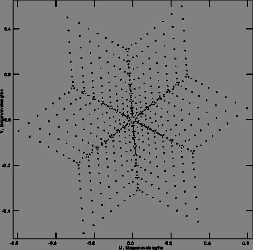
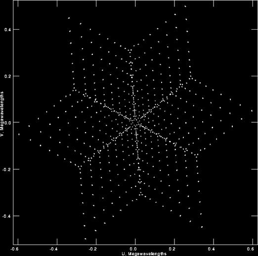
4 Indirect imaging Array provides (poorly) sampled Fourier Transform of the radio brightness region of sky V (u, v) = RR I(l, m)e 2πi(ul+vm) dldm u,v are the co-ordinates in the aperture plane, or visibility plane, perpendicular to the direction to the object, measured in wavelengths. At any instant the separation vector between each pair of telescopes can be plotted as a point in the visibility plane l.m are sky co-ordinates Assumed small region to be mapped 2D transform Region << individual antenna beam If V measured for all u,v to ±, inverse FT would yield I(l.m) We have set of samples of V(u,v). Define sampling function S(u,v) = 1 at measured (u,v), zero elsewhere
5 Convolution theorem Initial image is inverse transform of sampled visibility function I 0 (x, y) =F 1 [S(u, v)v (u, v)] using the convolution theorem I 0 (x, y) =B(x, y) I(x, y) where B(x, y) =F 1 S(u, v) is the Point Spread Function response of array to a unit point source at the origin General description of an imaging system Sometimes quite benign (HST) But a severe limitation for radio arrays Will want to minimize its effect
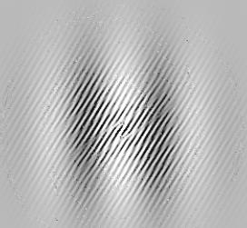
6 Illustration Measured visibilities V True visibility V Sampling S = X Dirty Map I True Sky I Dirty Beam B = *
7 Fourier Transforms Information distributed across the Fourier Plane Sky is real, therefore uv plane is symmetric (Hermitian) Single point in image -> const amplitude, phase gradient in u- v plane, with slope dependent on distance from origin Shift theorem Phase is important Single point in (u,v)-> sine-wave ripple in image Short baselines (small u,v) -> large scale smooth features Smooth emission > 1/umin invisible Interferometers filter out smooth emission Long baselines (large u,v) -> fine scale structure, sharp edges Resolution is 1/umax Gaps in u-v plane produce sidelobes of the PSF

8 Fourier Transform Phase Party Trick Rick Linda


9 FFT and Gridding Fast Fourier Transform (FFT) much faster to compute than DFT For NxN image DFT:few x N 4 ops FFT:few x N 2 logn Requires V (u,v) to be interpolated on to regular grid of 2 N x 2 M points Automatically generates an NxM pixel image In practice, specify the image grid as NxM pixels with a cellsize approx 1/3 of the expected resolution.
10 FFT and Gridding Fast Fourier Transform (FFT) much faster to compute than DFT For NxN image DFT:few x N 4 ops FFT:few x N 2 logn uv plane Grid spacing: Δu Size: u max Requires V (u,v) to be interpolated on to regular grid of 2 N x 2 M points Automatically generates an NxM pixel image In practice, specify the image grid as NxM pixels with a cellsize approx 1/3 of the expected resolution. Image Grid spacing: 1/(u max ) Size: 1/(Δu)
11 Gridding (2) Convolve measured points with some narrow function C (width ~ Δu), then resample on regular grid, then FFT In uv-plane: convolved with C and multiplied with III (series of δ-functions) Image is multiplied with FT(C) and convolved with III Multiplication slight taper at edge of image: easily corrected by 1/[FT(C)] Replication aliasing: emission outside region defined by FFT of uv grid appears inside image [Fundamentally a result of undersampling: the uv cells are too large because the image region is too small]

12 Gridding by convolution
13 Gridding and aliasing (3) Choice of convolution function Rectangle, width Δu (cell averaging) FT is sinc(πδul) Gaussian, width ~ Δu FT is Gaussian width 1/Δu Ideally want rectangle in image plane would remove aliasing but then the convolving function would be sinc(δu), with envelope falling as 1/(Δu ) would have to evaluate at every cell. Compromise: sinc x Gaussian convolving kernel Optimum: spheroidal function [non-analytic, look-up table]
14 Gridding (4)
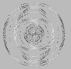
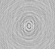
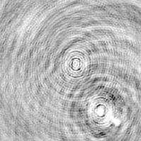
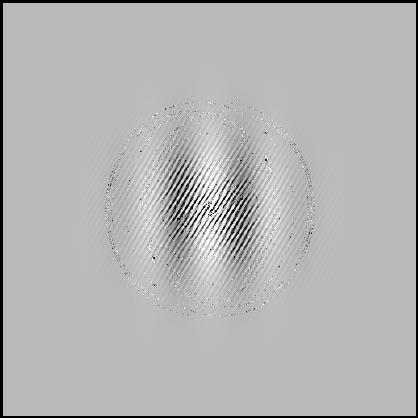
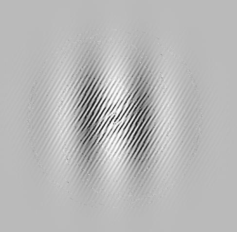
15 Dirty map & dirty beam Obtain initial image (dirty image) by gridded FFT of visibility data I 0 (x, y) =B(x, y) I(x, y) Dirty image = True image * Dirty Beam (PSF) Properties of Dirty Beam Response to a unit point source FT of sampling in uv plane Central maximum has width 1/(u max ) in x and 1/(v max ) in y Has ripples (sidelobes) Rms ~ 1/N (antennas) Close-in sidelobes: determined by envelope of uv points Far-out sidelobes due to gaps in uv coverage


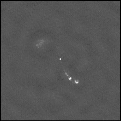
16 uv coverage and dirty beam VLA snapshot MERLIN track
17 Recovering true image Deconvolution I = I*B V =V.S Cannot use linear deconvolution (eg Wiener filter), because S(u,v) is zero in unsampled parts of uv plane Need to guess FT of true image in these regions Many different images whose FTs consistent with measured points but behave differently in the gaps The Dirty map is just the one which is zero at all these points How to select the right or best one Non-linear deconvolution methods try to do this as a result they interpolate into the unsampled parts of the uv plane
18 Extra information Choose best image using a priori information. Sky is positive Sky is often mostly empty with a few localised sources Individual regions of the sky may have smooth distribution of emission Best fit problem subject to constraints
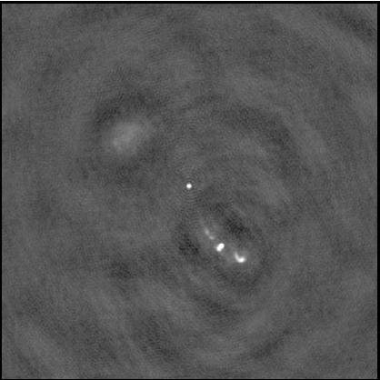
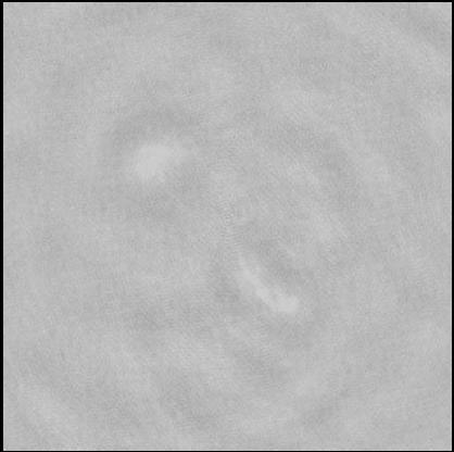
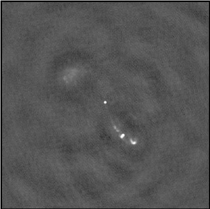
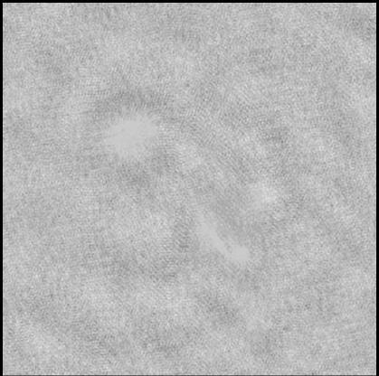
19 CLEAN Natural response to the problem, when faced with typical early images of compact radio sources subtract off Dirty Beam Procedure Produce Dirty Image, Dirty Beam Locate peak in dirty image Record position and intensity CLEAN COMPONENTS Subtract scaled & shifted dirty beam RESIDUAL IMAGE Locate next peak Continue until residual = noise Convolve clean components with clean beam (Gaussian fit to central dirty beam) Add to residual map CLEAN IMAGE
20 CLEAN demo
21 CLEAN demo
22 CLEAN demo
23 CLEAN demo
24 CLEAN demo
25 CLEAN demo
26 CLEAN demo

27 CLEAN demo
28
29 CLEAN demo in uv plane
30 CLEAN demo in uv plane
31 CLEAN demo in uv plane
32 CLEAN demo in uv plane
33 CLEAN demo in uv plane
34 CLEAN demo in uv plane
35 CLEAN demo in uv plane
36 CLEAN demo in uv plane

37 CLEAN demo in uv plane
38
39 Using CLEAN Using windows Restrict areas where clean components can be found Simple way to add stronger a priori information Significant impact for extended sources where uv coverage is poor User bias Choice of loop gain Usually When to stop CLEAN will happily deconvolve the noise Noise-only map has features (FT only non-zero on S(u,v)) Generally reduces apparent noise CLEAN bias for VLA snapshots (FIRST survey) Adding zero spacing Should help for extended sources; rarely used NB total flux in DM = V(0,0) = 0
40 Variants of CLEAN Classic Clean due to Högbom (1974) Clark Clean In image plane, use a restricted beam patch for subtracting a number of clean components Then do full subtraction of this set in visibility plane (FFT) Back to image plane and locate next set ~10x faster Cotton-Schwab As above but so subtraction from un-gridded data (DFT). More accurate, can work on multiple fields at once
41 CLEAN problems Well suited to isolated, compact sources Sidelobe pattern easily recognised, sources well represented by modest number of delta functions Might fail for very extended, smooth emission Well-known stripe instability Subtraction of sidelobe pattern from smooth region generates ripples, reinforced by further subtraction
42 Weighting After gridding not all cells equal Some receive many more points than others For earth-rotation synthesis, rate of traversing cells scales with baseline length. Long baselines can clip cells Some baselines (telescopes) may be more sensitive (VLBI, MERLIN)
43 Weighting After gridding not all cells equal Some receive many more points than others For earth-rotation synthesis, rate of traversing cells scales with baseline length. Long baselines can clip cells Some baselines (telescopes) may be more sensitive (VLBI, MERLIN)
44 Weighting (2) Can optimise sensitivity W i =1/(σ i2 ) taking into account points/cell and individual point weights Natural weighting highest weight on shorter baselines, so reduces resolution (makes dirty beam broader) Discontinuity in weights higher sidelobe levels Can minimize sidelobes W i =1/(ρ(u,v)) Optimum resolution and sidelobe level Reduced sensitivity Uniform or inverse density weighting


45 Weighting affects dirty beam Natural Uniform
46 Weighting affects dirty beam Natural Uniform
47 Robust weighting Developed by Briggs (1995) Combine inverse density and noise weighting Possible to get (almost) best of both worlds Adjust using robust parameter in IMAGR
48 Robust weighting Developed by Briggs (1995) Combine inverse density and noise weighting Possible to get (almost) best of both worlds Adjust using robust parameter in IMAGR
49 Alternative deconvolution methods Maximum Entropy Method (MEM) Primary contraint is to maximimize the Entropy Smoothest image which fits the measured data Simplest (minimum information) image which fits the data Non-negative least squares (NNLS) Primary constraint is positivity
50 Maximum Entropy Method Strong philosophical basis in information theory (Jaynes, Gull & Daniell); consistent treatment of prior information Maximise H ( I ) = I log( I m ) k k Practically: works well for extended emission, produces smoother results than CLEAN Can be faster for large images k Imagine single smooth component Does not cope well with point sources + smooth background Can use both; CLEAN to remove bright points; MEM on smoother residual image k
51 AIPS IMAGR Well developed and well-trusted implementation of Cotton-Schwab CLEAN with many enhancements (multiple fields, robust weighting, ) Input is (calibrated) visibility file Applies calibrations Uses convolution to grid data, applying specified weighting Produces Dirty Map, Dirty Beam Performs certain number of CLEAN subtractions Clean Component Table, Residual Map Convolves Clean Components with Clean Beam and adds Residual Map Writes out Clean Map as image file, with CC table attached
52 IMAGR parameters Simple use for single frequency, total intensity data: IMSIZE size of image in pixels: CELLSIZE pixel size in arcsec ~ 0.3 x resolution NITER can be fixed number of subtractions eg 1000; can control interactively with DOTV, or can stop when FLUX limit reached Options RASHIFT, DECSHIFT: move the centre of the field ROBUST: modify the weighting CLBOX (or set in DOTV mode) windows NFIELD > 1, RASHIFT, DECSHIFT multiple fields at the same time BMAJ, BMIN: set the CLEAN beam yourself Often made circular ~ sqrt(bx.by)
Introduction to Imaging in CASA
 Introduction to Imaging in CASA Mark Rawlings, Juergen Ott (NRAO) Atacama Large Millimeter/submillimeter Array Expanded Very Large Array Robert C. Byrd Green Bank Telescope Very Long Baseline Array Overview
INTERFEROMETRY: II Nissim Kanekar (NCRA TIFR)
") INTERFEROMETRY: II Nissim Kanekar (NCRA TIFR) WSRT GMRT VLA ATCA ALMA SKA MID PLAN Introduction. The van Cittert Zernike theorem. A 2 element interferometer. The fringe pattern. 2 D and 3 D interferometers.
INTERFEROMETRY: II Nissim Kanekar (NCRA TIFR) WSRT GMRT VLA ATCA ALMA SKA MID PLAN Introduction. The van Cittert Zernike theorem. A 2 element interferometer. The fringe pattern. 2 D and 3 D interferometers.
Fourier Transforms in Radio Astronomy
 Fourier Transforms in Radio Astronomy Kavilan Moodley, UKZN Slides taken from N Gupta s lectures: SKA School 2013 van-cittert Zernike theorem Extended, quasi-monochromatic, incoherent source X (l,m) Y
Deconvolution. Amy Mioduszewski National Radio Astronomy Observatory. Synthesis Imaging g in Radio Astronomy
 Deconvolution Amy Mioduszewski National Radio Astronomy Observatory Synthesis Imaging g in Radio Astronomy (based on a talk given by David Wilner (CfA) at the NRAO s 2010 Synthesis Imaging Workshop) 1
The Basics of Radio Interferometry. Frédéric Boone LERMA, Observatoire de Paris
 The Basics of Radio Interferometry LERMA, Observatoire de Paris The Basics of Radio Interferometry The role of interferometry in astronomy = role of venetian blinds in Film Noir 2 The Basics of Radio Interferometry
Fundamentals of Interferometry
 Fundamentals of Interferometry ERIS, Rimini, Sept 5-9 2011 Outline What is an interferometer? Basic theory Interlude: Fourier transforms for birdwatchers Review of assumptions and complications Interferometers
Radio Astronomy: SKA-Era Interferometry and Other Challenges. Dr Jasper Horrell, SKA SA (and Dr Oleg Smirnov, Rhodes and SKA SA)
") Radio Astronomy: SKA-Era Interferometry and Other Challenges Dr Jasper Horrell, SKA SA (and Dr Oleg Smirnov, Rhodes and SKA SA) ASSA Symposium, Cape Town, Oct 2012 Scope SKA antenna types Single dishes
Radio Astronomy: SKA-Era Interferometry and Other Challenges Dr Jasper Horrell, SKA SA (and Dr Oleg Smirnov, Rhodes and SKA SA) ASSA Symposium, Cape Town, Oct 2012 Scope SKA antenna types Single dishes
Why? When? How What to do What to worry about
 Tom Muxlow Data Combination Why? When? How What to do What to worry about Combination imaging or separate imaging??..using (e-)merlin (e-)merlin covers a unique range of telescope separations, intermediate
Introduction to Interferometry. Michelson Interferometer. Fourier Transforms. Optics: holes in a mask. Two ways of understanding interferometry
 Introduction to Interferometry P.J.Diamond MERLIN/VLBI National Facility Jodrell Bank Observatory University of Manchester ERIS: 5 Sept 005 Aim to lay the groundwork for following talks Discuss: General
Fundamentals of Interferometry
 Fundamentals of Interferometry ERIS, Dwingeloo, Sept 8-13 2013 Outline What is an interferometer? Basic theory Interlude: Fourier transforms for birdwatchers Review of assumptions and complications Interferometers
Wide-Band Imaging. Outline : CASS Radio Astronomy School Sept 2012 Narrabri, NSW, Australia. - What is wideband imaging?
 Wide-Band Imaging 24-28 Sept 2012 Narrabri, NSW, Australia Outline : - What is wideband imaging? - Two Algorithms Urvashi Rau - Many Examples National Radio Astronomy Observatory Socorro, NM, USA 1/32
Fundamentals of Radio Interferometry. Robert Laing (ESO)
") Fundamentals of Radio Interferometry Robert Laing (ESO) 1 ERIS 2015 Objectives A more formal approach to radio interferometry using coherence functions A complementary way of looking at the technique Simplifying
Fundamentals of Radio Interferometry Robert Laing (ESO) 1 ERIS 2015 Objectives A more formal approach to radio interferometry using coherence functions A complementary way of looking at the technique Simplifying
Mosaicking. Brian Mason (NRAO) Sixteenth Synthesis Imaging Workshop May 2018
 Sixteenth Synthesis Imaging Workshop May 2018") Mosaicking Brian Mason (NRAO) Sixteenth Synthesis Imaging Workshop 16-23 May 2018 The simplest observing scenario for an interferometer: Source at known location Size
Mosaicking Brian Mason (NRAO) Sixteenth Synthesis Imaging Workshop 16-23 May 2018 The simplest observing scenario for an interferometer: Source at known location Size
Imaging Simulations with CARMA-23
 BIMA memo 101 - July 2004 Imaging Simulations with CARMA-23 M. C. H. Wright Radio Astronomy laboratory, University of California, Berkeley, CA, 94720 ABSTRACT We simulated imaging for the 23-antenna CARMA
Wide Bandwidth Imaging
 Wide Bandwidth Imaging 14th NRAO Synthesis Imaging Workshop 13 20 May, 2014, Socorro, NM Urvashi Rau National Radio Astronomy Observatory 1 Why do we need wide bandwidths? Broad-band receivers => Increased
Radio Interferometer Array Point Spread Functions I. Theory and Statistics
 ALMA MEMO 389 Radio Interferometer Array Point Spread Functions I. Theory and Statistics David Woody Abstract This paper relates the optical definition of the PSF to radio interferometer arrays. The statistical
EVLA and LWA Imaging Challenges
 EVLA and LWA Imaging Challenges Steven T. Myers IGPP, Los Alamos National Laboratory and National Radio Astronomy Observatory, Socorro, NM 1 EVLA key issues 2 Key algorithmic issues ambitious goals / hard
Volume 82 VERY LONG BASELINE INTERFEROMETRY AND THE VLBA. J. A. Zensus, P. J. Diamond, and P. J. Napier
 ASTRONOMICAL SOCIETY OF THE PACIFIC CONFERENCE SERIES Volume 82 VERY LONG BASELINE INTERFEROMETRY AND THE VLBA Proceedings of a Summer School held in Socorro, New Mexico 23-30 June 1993 NRAO Workshop No.
Wide-field, wide-band and multi-scale imaging - II
 Wide-field, wide-band and multi-scale imaging - II Radio Astronomy School 2017 National Centre for Radio Astrophysics / TIFR Pune, India 28 Aug 8 Sept, 2017 Urvashi Rau National Radio Astronomy Observatory,
Next Generation Very Large Array Memo No. 16 More on Synthesized Beams and Sensitivity. C.L. Carilli, NRAO, PO Box O, Socorro, NM
 Next Generation Very Large Array Memo No. 16 More on Synthesized Beams and Sensitivity C.L. Carilli, NRAO, PO Box O, Socorro, NM Abstract I present further calculations on synthesized beams and sensitivities
GPU based imager for radio astronomy
 GPU based imager for radio astronomy GTC2014, San Jose, March 27th 2014 S. Bhatnagar, P. K. Gupta, M. Clark, National Radio Astronomy Observatory, NM, USA NVIDIA-India, Pune NVIDIA-US, CA Introduction
Large-field imaging. Frédéric Gueth, IRAM Grenoble. 7th IRAM Millimeter Interferometry School 4 8 October 2010
 Large-field imaging Frédéric Gueth, IRAM Grenoble 7th IRAM Millimeter Interferometry School 4 8 October 2010 Large-field imaging The problems The field of view is limited by the antenna primary beam width
Fundamentals of Radio Interferometry
 Fundamentals of Radio Interferometry Rick Perley, NRAO/Socorro ATNF Radio Astronomy School Narrabri, NSW 29 Sept. 03 Oct. 2014 Topics Introduction: Sensors, Antennas, Brightness, Power Quasi-Monochromatic
USE OF FT IN IMAGE PROCESSING IMAGE PROCESSING (RRY025)
") IMAGE PROCESSIG (RRY25) USE OF FT I IMAGE PROCESSIG Optics- originofimperfectionsinimagingsystems(limited resolution/blurring related to 2D FTs)- need to understand using Continuous FT. Sampling -Capturecontinuousimageontoasetofdiscrete
IMAGE PROCESSIG (RRY25) USE OF FT I IMAGE PROCESSIG Optics- originofimperfectionsinimagingsystems(limited resolution/blurring related to 2D FTs)- need to understand using Continuous FT. Sampling -Capturecontinuousimageontoasetofdiscrete
Next Generation Very Large Array Memo No. 47 Resolution and Sensitivity of ngvla-revb. C.L. Carilli (NRAO)
") Next Generation Very Large Array Memo No. 47 Resolution and Sensitivity of ngvla-revb C.L. Carilli (NRAO) Abstract I investigate the noise performance vs. resolution for the new ngvlarevb configuration.
Next Generation Very Large Array Memo No. 47 Resolution and Sensitivity of ngvla-revb C.L. Carilli (NRAO) Abstract I investigate the noise performance vs. resolution for the new ngvlarevb configuration.
Spectral Line II: Calibration and Analysis. Spectral Bandpass: Bandpass Calibration (cont d) Bandpass Calibration. Bandpass Calibration
 Bandpass Calibration. Bandpass Calibration") Spectral Line II: Calibration and Analysis Bandpass Calibration Flagging Continuum Subtraction Imaging Visualization Analysis Spectral Bandpass: Spectral frequency response of antenna to a spectrally flat
Spectral Line II: Calibration and Analysis Bandpass Calibration Flagging Continuum Subtraction Imaging Visualization Analysis Spectral Bandpass: Spectral frequency response of antenna to a spectrally flat
Practicalities of Radio Interferometry
 Practicalities of Radio Interferometry Rick Perley, NRAO/Socorro 13 th Synthesis Imaging Summer School 29 May 5 June, 2012 Socorro, NM Topics Practical Extensions to the Theory: Finite bandwidth Rotating
Fundamentals of Radio Interferometry
 Fundamentals of Radio Interferometry Rick Perley, NRAO/Socorro Fourteenth NRAO Synthesis Imaging Summer School Socorro, NM Topics Why Interferometry? The Single Dish as an interferometer The Basic Interferometer
Very Long Baseline Interferometry
 Very Long Baseline Interferometry Cormac Reynolds, JIVE European Radio Interferometry School, Bonn 12 Sept. 2007 VLBI Arrays EVN (Europe, China, South Africa, Arecibo) VLBA (USA) EVN + VLBA coordinate
ASTR Sequential Data 1D, cont.
 ASTR509-18 Sequential Data 1D, cont. Joseph Fourier 1768-1830 Three-way conflict priesthood/math/politics Jailed in 1794 for speaking out against the terror. Freed 1794. Ecole Normale tutors Lagrange and
Why Single Dish? Why Single Dish? Darrel Emerson NRAO Tucson
 Why Single Dish? Darrel Emerson NRAO Tucson Why Single Dish? What's the Alternative? Comparisons between Single-Dish, Phased Array & Interferometers Advantages and Disadvantages of Correlation Interferometer
Adaptive selective sidelobe canceller beamformer with applications in radio astronomy
 Adaptive selective sidelobe canceller beamformer with applications in radio astronomy Ronny Levanda and Amir Leshem 1 Abstract arxiv:1008.5066v1 [astro-ph.im] 30 Aug 2010 We propose a new algorithm, for
EVLA Memo 146 RFI Mitigation in AIPS. The New Task UVRFI
 EVLA Memo 1 RFI Mitigation in AIPS. The New Task UVRFI L. Kogan, F. Owen 1 (1) - National Radio Astronomy Observatory, Socorro, New Mexico, USA June, 1 Abstract Recently Ramana Athrea published a new algorithm
Phased Array Feeds & Primary Beams
 Phased Array Feeds & Primary Beams Aidan Hotan ASKAP Deputy Project Scientist 3 rd October 2014 CSIRO ASTRONOMY AND SPACE SCIENCE Outline Review of parabolic (dish) antennas. Focal plane response to a
Phased Array Feeds A new technology for multi-beam radio astronomy
 Phased Array Feeds A new technology for multi-beam radio astronomy Aidan Hotan ASKAP Deputy Project Scientist 2 nd October 2015 CSIRO ASTRONOMY AND SPACE SCIENCE Outline Review of radio astronomy concepts.
When, why and how to self-cal Nathan Brunetti, Crystal Brogan, Amanda Kepley
 When, why and how to self-cal Nathan Brunetti, Crystal Brogan, Amanda Kepley Atacama Large Millimeter/submillimeter Array Expanded Very Large Array Robert C. Byrd Green Bank Telescope Very Long Baseline
Phased Array Feeds A new technology for wide-field radio astronomy
 Phased Array Feeds A new technology for wide-field radio astronomy Aidan Hotan ASKAP Project Scientist 29 th September 2017 CSIRO ASTRONOMY AND SPACE SCIENCE Outline Review of radio astronomy concepts
Fundamentals of Radio Interferometry
 Fundamentals of Radio Interferometry Rick Perley, NRAO/Socorro 15 th Synthesis Imaging School Socorro, NM 01 09 June, 2016 Topics The Need for Interferometry Some Basics: Antennas as E-field Converters
Very Long Baseline Interferometry. Richard Porcas Max-Planck-Institut fuer Radioastronomie, Bonn
 Very Long Baseline Interferometry Richard Porcas Max-Planck-Institut fuer Radioastronomie, Bonn 1 Contents Introduction Principles and Practice of VLBI High angular resolution of long baselines The geophysics
ELEC Dr Reji Mathew Electrical Engineering UNSW
 ELEC 4622 Dr Reji Mathew Electrical Engineering UNSW Filter Design Circularly symmetric 2-D low-pass filter Pass-band radial frequency: ω p Stop-band radial frequency: ω s 1 δ p Pass-band tolerances: δ
Radio Interferometry -- II
 Radio Interferometry -- II Rick Perley, NRAO/Socorro ATNF School on Radio Astronomy Narrabri, NSW 29 Sept 3 Oct, 2014 Topics Practical Extensions to the Theory: Finite bandwidth Rotating reference frames
Error Recognition Emil Lenc (and Arin)
") Error Recognition Emil Lenc (and Arin) University of Sydney / CAASTRO www.caastro.org CASS Radio Astronomy School 2017 Based on lectures given previously by Ron Ekers and Steven Tingay CSIRO; Swinburne
Error Recognition Emil Lenc (and Arin) University of Sydney / CAASTRO www.caastro.org CASS Radio Astronomy School 2017 Based on lectures given previously by Ron Ekers and Steven Tingay CSIRO; Swinburne
2D Discrete Fourier Transform
 2D Discrete Fourier Transform In these lecture notes the figures have been removed for copyright reasons. References to figures are given instead, please check the figures yourself as given in the course
Radio Interferometry -- II
 Radio Interferometry -- II Rick Perley, NRAO/Socorro 15 th Synthesis Imaging Summer School June 1 9, 2016 Socorro, NM Topics Practical Extensions to the Theory: Real Sensors Finite bandwidth Rotating reference
The discrete charms of Redundant Spacing Calibration (RSC) J.E.Noordam. Madroon Community Consultants (MCC)
 J.E.Noordam. Madroon Community Consultants (MCC)") The discrete charms of Redundant Spacing Calibration (RSC) J.E.Noordam Madroon Community Consultants (MCC) Outline What is RSC? Advantages Limitations The place of RSC in the GST Diagnostic tool Fast first
The discrete charms of Redundant Spacing Calibration (RSC) J.E.Noordam Madroon Community Consultants (MCC) Outline What is RSC? Advantages Limitations The place of RSC in the GST Diagnostic tool Fast first
Spectral Line Observing
 Spectral Line Observing Ylva Pihlström, UNM Eleventh Synthesis Imaging Workshop Socorro, June 10-17, 2008 Introduction 2 Spectral line observers use many channels of width δν, over a total bandwidth Δν.
REDUCTION OF ALMA DATA USING CASA SOFTWARE
 REDUCTION OF ALMA DATA USING CASA SOFTWARE Student: Nguyen Tran Hoang Supervisor: Pham Tuan Anh Hanoi, September - 2016 1 CONTENS Introduction Interferometry Scientific Target M100 Calibration Imaging
Imaging and Calibration Algorithms for EVLA, e-merlin and ALMA. Robert Laing ESO
 Imaging and Calibration Algorithms for EVLA, e-merlin and ALMA Socorro, April 3 2008 Workshop details Oxford, 2008 Dec 1-3 Sponsored by Radionet and the University of Oxford 56 participants http://astrowiki.physics.ox.ac.uk/cgi-bin/twiki/view/algorithms2008/webhome
Sideband Smear: Sideband Separation with the ALMA 2SB and DSB Total Power Receivers
 and DSB Total Power Receivers SCI-00.00.00.00-001-A-PLA Version: A 2007-06-11 Prepared By: Organization Date Anthony J. Remijan NRAO A. Wootten T. Hunter J.M. Payne D.T. Emerson P.R. Jewell R.N. Martin
Principles of Radio Interferometry. Ast735: Submillimeter Astronomy IfA, University of Hawaii
 Principles of Radio Interferometry Ast735: Submillimeter Astronomy IfA, University of Hawaii 1 Resources IRAM millimeter interferometry school hdp://www.iram- inshtute.org/en/content- page- 248-7- 67-248-
Fourier Transform. Any signal can be expressed as a linear combination of a bunch of sine gratings of different frequency Amplitude Phase
 Fourier Transform Fourier Transform Any signal can be expressed as a linear combination of a bunch of sine gratings of different frequency Amplitude Phase 2 1 3 3 3 1 sin 3 3 1 3 sin 3 1 sin 5 5 1 3 sin
Heterogeneous Array Imaging with the CARMA Telescope
 Heterogeneous Array Imaging with the CARMA Telescope M. C. H. Wright Radio Astronomy laboratory, University of California, Berkeley, CA, 94720 February 1, 2011 ACKNOWLEDGMENTS Many people have made the
Plan for Imaging Algorithm Research and Development
 Plan for Imaging Algorithm Research and Development S. Bhatnagar July 05, 2009 Abstract Many scientific deliverables of the next generation radio telescopes require wide-field imaging or high dynamic range
Dealing with Noise. Stéphane GUILLOTEAU. Laboratoire d Astrophysique de Bordeaux Observatoire Aquitain des Sciences de l Univers
 Dealing with Noise Stéphane GUILLOTEAU Laboratoire d Astrophysique de Bordeaux Observatoire Aquitain des Sciences de l Univers I - Theory & Practice of noise II Low S/N analysis Outline 1. Basic Theory
Filters. Materials from Prof. Klaus Mueller
 Filters Materials from Prof. Klaus Mueller Think More about Pixels What exactly a pixel is in an image or on the screen? Solid square? This cannot be implemented A dot? Yes, but size matters Pixel Dots
Image-Domain Gridding on Accelerators
 Netherlands Institute for Radio Astronomy Image-Domain Gridding on Accelerators Bram Veenboer Monday 26th March, 2018, GPU Technology Conference 2018, San Jose, USA ASTRON is part of the Netherlands Organisation
Applying full polarization A-Projection to very-wide fields of view instruments: An imager for LOFAR Cyril Tasse
 Applying full polarization A-Projection to very-wide fields of view instruments: An imager for LOFAR Cyril Tasse ASTRON/Leiden: Joris van Zwieten, Bas van der Tol, Ger van Diepen NRAO: Sanjay Bhatnagar
Array Configuration for the Long Wavelength Intermediate Array (LWIA): Choosing the First Four Station Sites
: Choosing the First Four Station Sites") Array Configuration for the Long Wavelength Intermediate Array (LWIA): Choosing the First Four Station Sites Aaron Cohen (NRL) and Greg Taylor (UNM) December 4, 2007 ABSTRACT The Long Wavelength Intermediate
Array Configuration for the Long Wavelength Intermediate Array (LWIA): Choosing the First Four Station Sites Aaron Cohen (NRL) and Greg Taylor (UNM) December 4, 2007 ABSTRACT The Long Wavelength Intermediate
LOFAR: Special Issues
 Netherlands Institute for Radio Astronomy LOFAR: Special Issues John McKean (ASTRON) ASTRON is part of the Netherlands Organisation for Scientific Research (NWO) 1 Preamble http://www.astron.nl/~mckean/eris-2011-2.pdf
Radio Data Archives. how to find, retrieve, and image radio data: a lay-person s primer. Michael P Rupen (NRAO)
") Radio Data Archives how to find, retrieve, and image radio data: a lay-person s primer Michael P Rupen (NRAO) By the end of this talk, you should know: The standard radio imaging surveys that provide FITS
Radio Data Archives how to find, retrieve, and image radio data: a lay-person s primer Michael P Rupen (NRAO) By the end of this talk, you should know: The standard radio imaging surveys that provide FITS
LOFAR update: long baselines and other random topics
 LOFAR update: long baselines and other random topics AIfA/MPIfR lunch colloquium Olaf Wucknitz wucknitz@astro.uni-bonn.de Bonn, 6th April 20 LOFAR update: long baselines and other random topics LOFAR previous
SKA1 low Baseline Design: Lowest Frequency Aspects & EoR Science
 SKA1 low Baseline Design: Lowest Frequency Aspects & EoR Science 1 st science Assessment WS, Jodrell Bank P. Dewdney Mar 27, 2013 Intent of the Baseline Design Basic architecture: 3-telescope, 2-system
James M Anderson. in collaboration with Jan Noordam and Oleg Smirnov. MPIfR, Bonn, 2006 Dec 07
 Ionospheric Calibration for Long-Baseline, Low-Frequency Interferometry in collaboration with Jan Noordam and Oleg Smirnov Page 1/36 Outline The challenge for radioastronomy Introduction to the ionosphere
Practicalities of Radio Interferometry
 Practicalities of Radio Interferometry Rick Perley, NRAO/Socorro Fourth INPE Course in Astrophysics: Radio Astronomy in the 21 st Century Topics Practical Extensions to the Theory: Finite bandwidth Rotating
Introduction to Radio Interferometry Sabrina Stierwalt Alison Peck, Jim Braatz, Ashley Bemis
 Introduction to Radio Interferometry Sabrina Stierwalt Alison Peck, Jim Braatz, Ashley Bemis Atacama Large Millimeter/submillimeter Array Expanded Very Large Array Robert C. Byrd Green Bank Telescope Very
Pupil Planes versus Image Planes Comparison of beam combining concepts
 Pupil Planes versus Image Planes Comparison of beam combining concepts John Young University of Cambridge 27 July 2006 Pupil planes versus Image planes 1 Aims of this presentation Beam combiner functions
Cross-Talk in the ACS WFC Detectors. II: Using GAIN=2 to Minimize the Effect
 Cross-Talk in the ACS WFC Detectors. II: Using GAIN=2 to Minimize the Effect Mauro Giavalisco August 10, 2004 ABSTRACT Cross talk is observed in images taken with ACS WFC between the four CCD quadrants
Design of FIR Filters
 Design of FIR Filters Elena Punskaya www-sigproc.eng.cam.ac.uk/~op205 Some material adapted from courses by Prof. Simon Godsill, Dr. Arnaud Doucet, Dr. Malcolm Macleod and Prof. Peter Rayner 1 FIR as a
VLA CONFIGURATION STUDY - STATUS REPORT. February 27, 1968
 VLA CONFIGURATION STUDY - STATUS REPORT February 27, 1968 Summary of Work for the Period January 1967 - February 1968 The work done during the period under review can be divided into four categories: (i)
Cross Correlators. Jayce Dowell/Greg Taylor. University of New Mexico Spring Astronomy 423 at UNM Radio Astronomy
 Cross Correlators Jayce Dowell/Greg Taylor University of New Mexico Spring 2017 Astronomy 423 at UNM Radio Astronomy Outline 2 Re-cap of interferometry What is a correlator? The correlation function Simple
Examples of image processing
 Examples of image processing Example 1: We would like to automatically detect and count rings in the image 3 Detection by correlation Correlation = degree of similarity Correlation between f(x, y) and
Atacama Large Millimeter/submillimeter Array Expanded Very Large Array Robert C. Byrd Green Bank Telescope Very Long Baseline Array
 Atacama Large Millimeter/submillimeter Array Expanded Very Large Array Robert C. Byrd Green Bank Telescope Very Long Baseline Array Basics of Interferometry Data Reduction Scott Schnee (NRAO) ALMA Data
1.Discuss the frequency domain techniques of image enhancement in detail.
 1.Discuss the frequency domain techniques of image enhancement in detail. Enhancement In Frequency Domain: The frequency domain methods of image enhancement are based on convolution theorem. This is represented
Fundamentals of Radio Interferometry
 Fundamentals of Radio Interferometry Rick Perley, NRAO/Socorro Green Bank Interferometry School NRAO/GB 12 14 July, 2015 Topics The Need for Interferometry Some Basics: Antennas as E-field Converters Conceptual
The predicted performance of the ACS coronagraph
 Instrument Science Report ACS 2000-04 The predicted performance of the ACS coronagraph John Krist March 30, 2000 ABSTRACT The Aberrated Beam Coronagraph (ABC) on the Advanced Camera for Surveys (ACS) has
Lecture 3: Linear Filters
 Signal Denoising Lecture 3: Linear Filters Math 490 Prof. Todd Wittman The Citadel Suppose we have a noisy 1D signal f(x). For example, it could represent a company's stock price over time. In order to
Spectral Line Bandpass Removal Using a Median Filter Travis McIntyre The University of New Mexico December 2013
 Spectral Line Bandpass Removal Using a Median Filter Travis McIntyre The University of New Mexico December 2013 Abstract For spectral line observations, an alternative to the position switching observation
Why Single Dish? Darrel Emerson NRAO Tucson. NAIC-NRAO School on Single-Dish Radio Astronomy. Green Bank, August 2003.
 Why Single Dish? Darrel Emerson NRAO Tucson NAIC-NRAO School on Single-Dish Radio Astronomy. Green Bank, August 2003. Why Single Dish? What's the Alternative? Comparisons between Single-Dish, Phased Array
Chasing Faint Objects
 Chasing Faint Objects Image Processing Tips and Tricks Linz CEDIC 2015 Fabian Neyer 7. March 2015 www.starpointing.com Small Objects Large Objects RAW Data: Robert Pölzl usually around 1 usually > 1 Fabian
High Fidelity Imaging of Extended Sources. Rick Perley NRAO Socorro, NM
 High Fidelity Imaging of Extended Sources Rick Perley NRAO Socorro, NM A Brief History of Calibration (VLA) An Amazing Fact: The VLA was proposed, and funded, without any real concept of how to calibrate
Convolution Pyramids. Zeev Farbman, Raanan Fattal and Dani Lischinski SIGGRAPH Asia Conference (2011) Julian Steil. Prof. Dr.
 Julian Steil. Prof. Dr.") Zeev Farbman, Raanan Fattal and Dani Lischinski SIGGRAPH Asia Conference (2011) presented by: Julian Steil supervisor: Prof. Dr. Joachim Weickert Fig. 1.1: Gradient integration example Seminar - Milestones
Zeev Farbman, Raanan Fattal and Dani Lischinski SIGGRAPH Asia Conference (2011) presented by: Julian Steil supervisor: Prof. Dr. Joachim Weickert Fig. 1.1: Gradient integration example Seminar - Milestones
Parameterized Deconvolution for Wide-Band Radio Synthesis Imaging
 Parameterized Deconvolution for Wide-Band Radio Synthesis Imaging Urvashi Rao Venkata Ph.D. Thesis Defense Department of Physics, New Mexico Institute of Mining and Technology 17 May 2010 Advisors / Committee
DESIGN NOTE: DIFFRACTION EFFECTS
 NASA IRTF / UNIVERSITY OF HAWAII Document #: TMP-1.3.4.2-00-X.doc Template created on: 15 March 2009 Last Modified on: 5 April 2010 DESIGN NOTE: DIFFRACTION EFFECTS Original Author: John Rayner NASA Infrared
Aliasing and Antialiasing. What is Aliasing? What is Aliasing? What is Aliasing?
 What is Aliasing? Errors and Artifacts arising during rendering, due to the conversion from a continuously defined illumination field to a discrete raster grid of pixels 1 2 What is Aliasing? What is Aliasing?
Radio Interferometry. Xuening Bai. AST 542 Observational Seminar May 4, 2011
 Radio Interferometry Xuening Bai AST 542 Observational Seminar May 4, 2011 Outline Single-dish radio telescope Two-element interferometer Interferometer arrays and aperture synthesis Very-long base line
Error Recognition and Data Analysis
 Error Recognition and Data Analysis Greg Taylor (UNM) With help from: Urvashi Rao, Sanjay Bhatnagar, Gustaaf van Moorsel, Justin Linford, Ed Fomalont Fifteenth Synthesis Imaging Workshop 1-8 June 2016
Data processing with the RTS A GPU-accelerated calibration & imaging stream processor
 Data processing with the RTS A GPU-accelerated calibration & imaging stream processor Daniel Mitchell 2018 ICRAR/CASS Radio School CSIRO ASTRONOMY AND SPACE SCIENCE The RTS (Real-Time System) A GPU-accelerated
Atacama Large Millimeter/submillimeter Array Expanded Very Large Array Robert C. Byrd Green Bank Telescope Very Long Baseline Array
 Atacama Large Millimeter/submillimeter Array Expanded Very Large Array Robert C. Byrd Green Bank Telescope Very Long Baseline Array Self-Calibration Ed Fomalont (NRAO) ALMA Data workshop Dec. 2, 2011 Atacama
Radio Interferometers Around the World. Amy J. Mioduszewski (NRAO)
") Radio Interferometers Around the World Amy J. Mioduszewski (NRAO) A somewhat biased view of current interferometers Limited to telescopes that exist or are in the process of being built (i.e., I am not
Radio Interferometers Around the World Amy J. Mioduszewski (NRAO) A somewhat biased view of current interferometers Limited to telescopes that exist or are in the process of being built (i.e., I am not
Introduction to Radio Astronomy!
 Introduction to Radio Astronomy! Sources of radio emission! Radio telescopes - collecting the radiation! Processing the radio signal! Radio telescope characteristics! Observing radio sources Sources of
VLBI Post-Correlation Analysis and Fringe-Fitting
 VLBI Post-Correlation Analysis and Fringe-Fitting Michael Bietenholz With (many) Slides from George Moellenbroek and Craig Walker NRAO Calibration is important! What Is Delivered by a Synthesis Array?
High Contrast Imaging
 High Contrast Imaging Suppressing diffraction (rings and other patterns) Doing this without losing light Suppressing scattered light Doing THIS without losing light Diffraction rings arise from the abrupt
Today. Defocus. Deconvolution / inverse filters. MIT 2.71/2.710 Optics 12/12/05 wk15-a-1
 Today Defocus Deconvolution / inverse filters MIT.7/.70 Optics //05 wk5-a- MIT.7/.70 Optics //05 wk5-a- Defocus MIT.7/.70 Optics //05 wk5-a-3 0 th Century Fox Focus in classical imaging in-focus defocus
LAB MANUAL SUBJECT: IMAGE PROCESSING BE (COMPUTER) SEM VII
 SEM VII") LAB MANUAL SUBJECT: IMAGE PROCESSING BE (COMPUTER) SEM VII IMAGE PROCESSING INDEX CLASS: B.E(COMPUTER) SR. NO SEMESTER:VII TITLE OF THE EXPERIMENT. 1 Point processing in spatial domain a. Negation of an
LAB MANUAL SUBJECT: IMAGE PROCESSING BE (COMPUTER) SEM VII IMAGE PROCESSING INDEX CLASS: B.E(COMPUTER) SR. NO SEMESTER:VII TITLE OF THE EXPERIMENT. 1 Point processing in spatial domain a. Negation of an
A model for the SKA. Melvyn Wright. Radio Astronomy laboratory, University of California, Berkeley, CA, ABSTRACT
 SKA memo 16. 21 March 2002 A model for the SKA Melvyn Wright Radio Astronomy laboratory, University of California, Berkeley, CA, 94720 ABSTRACT This memo reviews the strawman design for the SKA telescope.
MAKING TRANSIENT ANTENNA MEASUREMENTS
 MAKING TRANSIENT ANTENNA MEASUREMENTS Roger Dygert, Steven R. Nichols MI Technologies, 1125 Satellite Boulevard, Suite 100 Suwanee, GA 30024-4629 ABSTRACT In addition to steady state performance, antennas
Aperture Antennas. Reflectors, horns. High Gain Nearly real input impedance. Huygens Principle
 Antennas 97 Aperture Antennas Reflectors, horns. High Gain Nearly real input impedance Huygens Principle Each point of a wave front is a secondary source of spherical waves. 97 Antennas 98 Equivalence
Introduction p. 1 Review of Radar Principles p. 1 Tracking Radars and the Evolution of Monopulse p. 3 A "Baseline" Monopulse Radar p.
 Preface p. xu Introduction p. 1 Review of Radar Principles p. 1 Tracking Radars and the Evolution of Monopulse p. 3 A "Baseline" Monopulse Radar p. 8 Advantages and Disadvantages of Monopulse p. 17 Non-Radar
Practical Radio Interferometry VLBI. Olaf Wucknitz.
 Practical Radio Interferometry VLBI Olaf Wucknitz wucknitz@astro.uni-bonn.de Bonn, 1 December 2010 VLBI Need for long baselines What defines VLBI? Techniques VLBI science Practical issues VLBI arrays how