Introduction to Radio Interferometry Sabrina Stierwalt Alison Peck, Jim Braatz, Ashley Bemis
|
|
|
- Kristina Berry
- 6 years ago
- Views:
Transcription

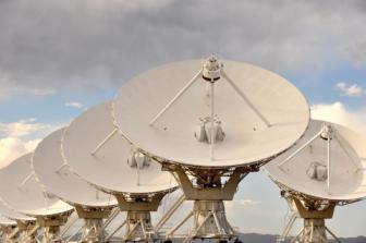
1 Introduction to Radio Interferometry Sabrina Stierwalt Alison Peck, Jim Braatz, Ashley Bemis Atacama Large Millimeter/submillimeter Array Expanded Very Large Array Robert C. Byrd Green Bank Telescope Very Long Baseline Array

2 Radio Astronomy Now used to refer to most telescopes using heterodyne technology NRAO Community Day 3/14/16 Event 2

3 What is heterodyne? In a heterodyne receiver, observed sky frequencies are converted to lower frequency signals by mixing with a signal artificially created by a Local Oscillator. The output can then be amplified and analyzed more easily while retaining the original phase and amplitude information. Image from Alessandro Navarrini (IRAM) 3
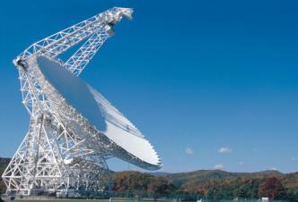

4 Long wavelength means no glass mirrors 4
 Jupiter s radiation")

 Images from NRAO Image")
5 What can we observe? (MHz-GHz range) Jupiter s radiation belt at 100MHz Relic emission from old radio galaxies Synchrotron emission from extended radio galaxies (5 GHz) Images from NRAO Image Gallery: 5

: H")

6 What can we observe? Images from NRAO Image Gallery At low frequencies (MHz-GHz): H 2 O, OH or SiO masers in galaxies and stars HI emission and absorption, free-free absorption in galaxies 6 3/1 4/1 6


7 What can we observe? At higher frequencies we can observe a broad range of molecular lines Images from ALMA Science Verification (Brogan) 7
8 Resolution of Observations Angular resolution for most telescopes is ~ λ/d D is the diameter of the telescope λ is wavelength of observation For example, Hubble Space Telescope: λ ~ 1um / D of 2.4m = resolution ~ 0.13 To reach that resolution for a λ ~1mm observation, one would need a 2 km-diameter dish! Instead, we use arrays of smaller dishes to achieve the same high angular resolution at radio frequencies This is interferometry 8


9 What is an interferometer? An interferometer measures the interference pattern produced by multiple apertures, much like a 2-slit experiment. *However, the interference patterns measured by radio telescopes are produced by multiplying - not adding - the wave signals measured at the different telescopes (i.e. apertures) 9
10 How do we use interferometry? A signal from space arrives at each antenna at a slightly different time (due to different travel lengths) depending on the location of the antenna in the array. The signal from each antenna is then combined with every other antenna in a correlator, where the time delay is measured and compensated for in the software. The signals arriving from slightly different points in the sky arrive at slightly different times at each antenna. This provides location information within the telescope beam and thus positional information about the emitting object. 2/2/16 10
11 Some instrument details Referenc e Correlator To precisely measure arrival times we need very accurate clocks At Band 10 one wavelength error = 1 picosecond (!!) We need << 1 wavelength timing precision so each antenna has an on-board clock with high sampling rates Once determined, the reference time is distributed to all antennas 11
12 Some instrument details Referenc e Correlator Signal from each antenna are digitized and sent to the correlator for multiplication & averaging. For ~50 antennas the data rate is 600 GB/sec for the correlator to process 12

13 An interferometer in action 13
14 The Fourier Transform Fourier theory states that any well behaved signal (including images) can be expressed as the sum of sinusoids Reference signal 4 sinusoids Sum of sinusoids & signal The Fourier transform is the mathematical tool that decomposes a signal into its sinusoidal components The Fourier transform contains all of the information of the original signal 14
15 The Fourier Transform relates the measured interference pattern to the radio intensity on the sky 1. An interferometer measures the interference pattern produced by pairs of apertures. 2. The interference pattern is directly related to the source brightness: For small fields-of-view: the complex visibility, V(u,v), is the 2D Fourier transform of the brightness on the sky, T(x,y) (van Cittert-Zernike theorem) 15
 y Image space/domain (for more info, see e.g. Thompson, Moran & Swenson) uv plane 16")
16 The Fourier Transform relates the measured interference pattern to the radio intensity on the sky Fourier space/domain image plane x T(x,y) y Image space/domain (for more info, see e.g. Thompson, Moran & Swenson) uv plane 16

17 Sign up for the Synthesis Imaging Workshop! 17
 Amp{V(u,v)} δ Function")

18 Some 2D Fourier Transform Pairs T(x,y) Amp{V(u,v)} δ Function Constant Gaussian Gaussian narrow features transform to wide features (and vice-versa)


19 2D Fourier Transform Pairs T(x,y) Amp{V(u,v)} elliptical Gaussian elliptical Gaussian Disk Bessel sharp edges result in many high spatial frequencies (sinc function, ringing, Gibbs phenomenon)
20 Visibility and Sky Brightness Graphic courtesy Andrea Isella 1 b 1 b 2 V 0.5 Δθ=λ/b 0 V = I max I min I max+ I min b 2 b 1 b (meters) Fringe Amplitude = Average Intensity phase The visibility is a complex quantity: - amplitude tells how much of a certain frequency component - phase tells where this component is located 20
 V = I max I min I max + I min = Fringe Amplitude Average")
21 Visibility and Sky Brightness Graphic courtesy Andrea Isella Resolved source 1 V 0.5 b 1 0 b 3 b 2 b 1 b (meters) V = I max I min I max + I min = Fringe Amplitude Average Intensity 21
22 Characteristic Angular Scales Angular resolution of telescope array: ~ λ/b max, where B max is the longest baseline Maximum angular scale: a source is resolved if the angular size > λ/b min (B min is the minimum separation between apertures) Field of view of a single aperture (single dish): ~ λ/d, where D is the diameter of the telescope. If sources are more extended than the FOV, it can be observed using multiple pointing centers in a mosaic. An interferometer is sensitive to a range of angular sizes λ/b max < θ < λ/b min Since B min > D, an interferometer is not sensitive to the large angular scales and cannot recover the total flux of resolved sources 22
23 Characteristic Angular Scales: M100 12m data reveals information on smaller spatial scales (denser, clumpier emission) 7m data reveals information on larger spatial scales (diffuse, extended emission) To get both: you need a combined image 23
24 Interferometry: Spatial Scales The sensitivity is given by the number of antennas times their area The field of view is given by the beam of a single antenna (corresponding to the resolution for a single dish telescope or the primary beam) The resolution is given by the largest distance between antennas (called the synthesized beam) The largest angular scale that can be imaged is given by the shortest distance between antennas
 2/2/16 NRAO Community Day Event 25")
25 Example: Fringe pattern with 2 Antennas (one baseline) 2/2/16 NRAO Community Day Event 25
 2/2/16 NRAO Community Day Event")
26 Example: Fringe pattern with 3 Antennas (3 baselines) 2/2/16 NRAO Community Day Event 26
 2/2/16 NRAO Community Day Event")
27 Example: Fringe pattern with 4 Antennas (6 baselines) 2/2/16 NRAO Community Day Event 27
 2/2/16 NRAO Community Day Event")
28 Example: Fringe pattern with 8 Antennas (28 baselines) 2/2/16 NRAO Community Day Event 28

29 16 Antennas Compact Configuration 2/2/16 NRAO Community Day Event 29
30 16 Antennas Extended Configuration 2/2/16 NRAO Community Day Event 30


31 32 Antennas Instantaneous 2/2/16 NRAO Community Day Event 31

32 32 Antennas 8 hours 2/2/16 NRAO Community Day Event 32

 Orientation of baseline also determines orientation")
33 Sampling Function Each antenna pair samples only one spot; the array cannot sample the entire Fourier/uv domain resulting in an imperfect image Small uv-distance: short baselines (measure extended emission) Long uv-distance: long baselines (measure small scale emission) Orientation of baseline also determines orientation in the uv-plane
34 uv coverage: why the central hole? The central hole in the sampling of the uv plane arises due to short baselines The largest angular scale that an interferometer is sensitive to is given by the shortest distance between 2 antennas. The field of view is given by the beam of a single antenna. A single antenna diameter will always be < the shortest distance between two antennas. So the field of view is always > the largest angular scale If your source is extended, you will always have some flux at short spacings (i.e. extended emission) that is not recovered. Solutions: We can extrapolate to these shorter spacings after our observations are taken (more on this tomorrow!) or we can fill in the information with 7m observations or ultimately single dish data.

35 Output of interferometric observation is in the form of a cube of data the third dimension is frequency. 35

 with infall")
36 Sometimes the most interesting science lies in the third dimension Band 6 J. Turner & ALMA CSV team Young Low Mass Stars: IRAS16293 Note narrow lines toward preprotostellar core B (top) with infall apparent in methyl formate and ketene lines. 36


37 How do we go from raw data to a cube? Interferometers measure visibilities, i.e., the amplitude and phase of the cross-correlated signals between pairs of antennas, as a function of time and frequency. We calibrate these data by determining the complex gains (amplitude and phase), the frequency response (bandpass) and flux scale for each antenna. Flux Bandpass Phase source Flux Bandpass source Phase 37
38 Observing Strategy Choose your array by largest angular scale of target Interferometers act as spatial filters - shorter baselines are sensitive to larger targets, so remember: Spatial scales larger than the smallest baseline cannot be imaged Spatial scales smallerthan the largest baseline cannot be resolved Calibration Requirements (Handled by ALMA): Gain calibrator:solves for atmospheric and instrumental variations with time. Usually a bright quasar near science target Bandpass calibrator: fixes instrumental effects and variations vs frequency Usually a bright quasar Absolute flux calibrator: used to scale relative amplitudes to absolute value Usually a solar system object or quasar 38
39 Calibration Process Calibration is the effort to measure and remove the time-dependent and frequency-dependent atmospheric and instrumental variations. Steps in calibrating interferometric data: (Note: You don t have to worry about these in your observational set up!) Bandpass calibration (correct frequency-dependent telescope response) Phase and amplitude gain calibration (remove effects of atmospheric water vapor and correct time-varying phases/amplitudes) Set absolute flux scale

 * Done once in an SB,")
40 Bandpass Calibration: Phase * Analogous to optical flat fielding + bias subtraction for each antenna. * Primarily correcting for frequency dependent telescope response (i.e. in the correlator/spectral windows) * Done once in an SB, uses bright point sources like quasars * Typically, baseline responses are inverted to antenna-based correction Baselines to one antenna Antenna-based Bandpass Solutions 40
")
41 Bandpass Phase vs. Frequency (Before) 41
")
42 Bandpass Phase vs. Frequency (After)

43 Bandpass Calibration: Amplitude Baselines to one antenna Amplitude Before Bandpass Calibration Bandpass solutions for individual antennas 43
44 Atmospheric Phase Correction Variations in the amount of precipitable water vapor cause phase fluctuations that result in: Low coherence (loss of sensitivity) Radio seeing of 1arcsec at 1mm Anomalous pointing offsets Anomalous delay offsets Patches of air with different water vapor content (and hence index of refraction) affect the incoming wave front differently. 44
45 Phase & Amplitude Gain Calibration Determines the variations of phase and amplitude over time First pass is atmospheric correction from Water Vapor Radiometers readings Final correction from gain calibrator (point source near to target) that is observed every few minutes throughout the observation (analogous to repeat trips to a standard star) 45

46 Water Vapor Correction on ALMA Phase vs. Time One 600m Baseline ~600 GHz Before WVR, After WVR 46
47 Phase Calibration The phase calibrator must be a point source close to the science target and must be observed frequently. This provides a model of atmospheric phase change along the line of sight to the science target that can be compensated for in the data. Phase Time Corrected using point source model 47
. If the source is resolved, or has spectral lines, it must be modeled very well.")
48 Two Steps: Flux (or Amplitude) Calibration 1. Use calibration devices with known temperatures (hotload and ambient load) to measure System Temperature frequently. 2. Use a source of known flux to convert the signal measured at the antenna to common unit (Janskys). If the source is resolved, or has spectral lines, it must be modeled very well. The derived amplitude vs. time corrections for the flux calibrator are then applied to the science target. 48
49 Amp-Calibrators Amp vs. uv-distance (Before) 2/2/16 NRAO Community Day Event 49
50 Amp-Calibrators Amp vs. uv-distance (Model) 2/2/16 NRAO Community Day Event 50
51 Amp-Calibrators Amp vs. uv-distance (After) 2/2/16 NRAO Community Day Event 51
52 Some good references Thompson, A.R., Moran, J.M., Swensen, G.W Interferometry and Synthesis in Radio Astronomy, 2nd edition (Wiley-VCH) Perley, R.A., Schwab, F.R., Bridle, A.H. eds ASP Conf. Series 6 Synthesis Imaging in Radio Astronomy (San Francisco: ASP) IRAM Interferometry School proceedings 52
, an international astronomy facility, is a partnership of the European Organisation for Astronomical Research in the Southern Hemisphere")
53 For more info: The Atacama Large Millimeter/submillimeter Array (ALMA), an international astronomy facility, is a partnership of the European Organisation for Astronomical Research in the Southern Hemisphere (ESO), the U.S. National Science Foundation (NSF) and the National Institutes of Natural Sciences (NINS) of Japan in cooperation with the Republic of Chile. ALMA is funded by ESO on behalf of its Member States, by NSF in cooperation with the National Research Council of Canada (NRC) and the National Science Council of Taiwan (NSC) and by NINS in cooperation with the Academia Sinica (AS) in Taiwan and the Korea Astronomy and Space Science Institute (KASI). ALMA construction and operations are led by ESO on behalf of its Member States; by the National Radio Astronomy Observatory (NRAO), managed by Associated Universities, Inc. (AUI), on behalf of North America; and by the National Astronomical Observatory of Japan (NAOJ) on behalf of East Asia. The Joint ALMA Observatory (JAO) provides the unified leadership and management of the construction, commissioning and operation of ALMA. 53
Introduction to Radio Interferometry Anand Crossley Alison Peck, Jim Braatz, Ashley Bemis (NRAO)
") Introduction to Radio Interferometry Anand Crossley Alison Peck, Jim Braatz, Ashley Bemis (NRAO) Atacama Large Millimeter/submillimeter Array Expanded Very Large Array Robert C. Byrd Green Bank Telescope
Introduction to Radio Interferometry Anand Crossley Alison Peck, Jim Braatz, Ashley Bemis (NRAO) Atacama Large Millimeter/submillimeter Array Expanded Very Large Array Robert C. Byrd Green Bank Telescope
Technical Considerations: Nuts and Bolts Project Planning and Technical Justification
 Technical Considerations: Nuts and Bolts Project Planning and Technical Justification Atacama Large Millimeter/submillimeter Array Expanded Very Large Array Robert C. Byrd Green Bank Telescope Very Long
REDUCTION OF ALMA DATA USING CASA SOFTWARE
 REDUCTION OF ALMA DATA USING CASA SOFTWARE Student: Nguyen Tran Hoang Supervisor: Pham Tuan Anh Hanoi, September - 2016 1 CONTENS Introduction Interferometry Scientific Target M100 Calibration Imaging
Atacama Large Millimeter/submillimeter Array Expanded Very Large Array Robert C. Byrd Green Bank Telescope Very Long Baseline Array
 Atacama Large Millimeter/submillimeter Array Expanded Very Large Array Robert C. Byrd Green Bank Telescope Very Long Baseline Array Basics of Interferometry Data Reduction Scott Schnee (NRAO) ALMA Data
Principles of Radio Interferometry. Ast735: Submillimeter Astronomy IfA, University of Hawaii
 Principles of Radio Interferometry Ast735: Submillimeter Astronomy IfA, University of Hawaii 1 Resources IRAM millimeter interferometry school hdp://www.iram- inshtute.org/en/content- page- 248-7- 67-248-
Introduction to Imaging in CASA
 Introduction to Imaging in CASA Mark Rawlings, Juergen Ott (NRAO) Atacama Large Millimeter/submillimeter Array Expanded Very Large Array Robert C. Byrd Green Bank Telescope Very Long Baseline Array Overview
INTERFEROMETRY: II Nissim Kanekar (NCRA TIFR)
") INTERFEROMETRY: II Nissim Kanekar (NCRA TIFR) WSRT GMRT VLA ATCA ALMA SKA MID PLAN Introduction. The van Cittert Zernike theorem. A 2 element interferometer. The fringe pattern. 2 D and 3 D interferometers.
INTERFEROMETRY: II Nissim Kanekar (NCRA TIFR) WSRT GMRT VLA ATCA ALMA SKA MID PLAN Introduction. The van Cittert Zernike theorem. A 2 element interferometer. The fringe pattern. 2 D and 3 D interferometers.
What is CASA? Rachel Friesen. North American ALMA Science Center. Victoria BC, January 18, 2011 ALMA Software Tutorial 1
 What is CASA? Rachel Friesen North American ALMA Science Center Victoria BC, January 18, 2011 ALMA Software Tutorial 1 Outline Introduction and Current Status General tools and tasks CASA in use! CASA
Introduction to Interferometry. Michelson Interferometer. Fourier Transforms. Optics: holes in a mask. Two ways of understanding interferometry
 Introduction to Interferometry P.J.Diamond MERLIN/VLBI National Facility Jodrell Bank Observatory University of Manchester ERIS: 5 Sept 005 Aim to lay the groundwork for following talks Discuss: General
Interferometry I Parkes Radio School Jamie Stevens ATCA Senior Systems Scientist
 Interferometry I Parkes Radio School 2011 Jamie Stevens ATCA Senior Systems Scientist 2011-09-28 References This talk will reuse material from many previous Radio School talks, and from the excellent textbook
Imaging Simulations with CARMA-23
 BIMA memo 101 - July 2004 Imaging Simulations with CARMA-23 M. C. H. Wright Radio Astronomy laboratory, University of California, Berkeley, CA, 94720 ABSTRACT We simulated imaging for the 23-antenna CARMA
Atacama Large Millimeter Array Project Status. M. Tarenghi ALMA Director
 Atacama Large Millimeter Array Project Status M. Tarenghi ALMA Director Atacama Large Millimeter Array Specifications Partners: US (NSF)+Canada (NRC) - ESO+Spain - Chile 64 12-m antennas, at 5000 m altitude
Radio Interferometry. Xuening Bai. AST 542 Observational Seminar May 4, 2011
 Radio Interferometry Xuening Bai AST 542 Observational Seminar May 4, 2011 Outline Single-dish radio telescope Two-element interferometer Interferometer arrays and aperture synthesis Very-long base line
Planning ALMA Observations
 Planning Observations Atacama Large mm/sub-mm Array Mark Lacy North American Science Center Atacama Large Millimeter/submillimeter Array Expanded Very Large Array Robert C. Byrd Green Bank Telescope Very
The Basics of Radio Interferometry. Frédéric Boone LERMA, Observatoire de Paris
 The Basics of Radio Interferometry LERMA, Observatoire de Paris The Basics of Radio Interferometry The role of interferometry in astronomy = role of venetian blinds in Film Noir 2 The Basics of Radio Interferometry
Large-field imaging. Frédéric Gueth, IRAM Grenoble. 7th IRAM Millimeter Interferometry School 4 8 October 2010
 Large-field imaging Frédéric Gueth, IRAM Grenoble 7th IRAM Millimeter Interferometry School 4 8 October 2010 Large-field imaging The problems The field of view is limited by the antenna primary beam width
More Radio Astronomy
 More Radio Astronomy Radio Telescopes - Basic Design A radio telescope is composed of: - a radio reflector (the dish) - an antenna referred to as the feed on to which the radiation is focused - a radio
Fundamentals of Radio Interferometry
 Fundamentals of Radio Interferometry Rick Perley, NRAO/Socorro Fourteenth NRAO Synthesis Imaging Summer School Socorro, NM Topics Why Interferometry? The Single Dish as an interferometer The Basic Interferometer
Observing Modes and Real Time Processing
 2010-11-30 Observing with ALMA 1, Observing Modes and Real Time Processing R. Lucas November 30, 2010 Outline 2010-11-30 Observing with ALMA 2, Observing Modes Interferometry Modes Interferometry Calibrations
EVLA Memo 105. Phase coherence of the EVLA radio telescope
 EVLA Memo 105 Phase coherence of the EVLA radio telescope Steven Durand, James Jackson, and Keith Morris National Radio Astronomy Observatory, 1003 Lopezville Road, Socorro, NM, USA 87801 ABSTRACT The
Fourier Transforms in Radio Astronomy
 Fourier Transforms in Radio Astronomy Kavilan Moodley, UKZN Slides taken from N Gupta s lectures: SKA School 2013 van-cittert Zernike theorem Extended, quasi-monochromatic, incoherent source X (l,m) Y
ALMA. ALMA Construction Status. Mark McKinnon. ALMA-NA Project Director/Manager September 28, 2011
 Construction Status Mark McKinnon -NA Project Director/Manager September 28, 2011 Antennas at AOS 18 antennas August 13, 2011 17 antennas August 6, 2011 Total of 44 antennas at the site (21NA, 13 EA, 10
Deconvolution. Amy Mioduszewski National Radio Astronomy Observatory. Synthesis Imaging g in Radio Astronomy
 Deconvolution Amy Mioduszewski National Radio Astronomy Observatory Synthesis Imaging g in Radio Astronomy (based on a talk given by David Wilner (CfA) at the NRAO s 2010 Synthesis Imaging Workshop) 1
The ALMA Front End. Hans Rudolf
 The ALMA Front End Hans Rudolf European Southern Observatory, ALMA, Karl-Schwarzschild-Straße 2, 85748 Garching, Germany, +49-89-3200 6397, hrudolf@eso.org Abstract The Atacama Large Millimeter Array (ALMA)
Atacama Large Millimeter/submillimeter Array Expanded Very Large Array Robert C. Byrd Green Bank Telescope Very Long Baseline Array
 Atacama Large Millimeter/submillimeter Array Expanded Very Large Array Robert C. Byrd Green Bank Telescope Very Long Baseline Array Self-Calibration Ed Fomalont (NRAO) ALMA Data workshop Dec. 2, 2011 Atacama
Sideband Smear: Sideband Separation with the ALMA 2SB and DSB Total Power Receivers
 and DSB Total Power Receivers SCI-00.00.00.00-001-A-PLA Version: A 2007-06-11 Prepared By: Organization Date Anthony J. Remijan NRAO A. Wootten T. Hunter J.M. Payne D.T. Emerson P.R. Jewell R.N. Martin
Planning (VLA) observations
 observations") Planning () observations 14 th Synthesis Imaging Workshop (May 2014) Loránt Sjouwerman National Radio Astronomy Observatory (Socorro, NM) Atacama Large Millimeter/submillimeter Array Karl G. Jansky Very
Planning () observations 14 th Synthesis Imaging Workshop (May 2014) Loránt Sjouwerman National Radio Astronomy Observatory (Socorro, NM) Atacama Large Millimeter/submillimeter Array Karl G. Jansky Very
Fundamentals of Interferometry
 Fundamentals of Interferometry ERIS, Rimini, Sept 5-9 2011 Outline What is an interferometer? Basic theory Interlude: Fourier transforms for birdwatchers Review of assumptions and complications Interferometers
ASTRO 6525 Lecture #18:! (Sub-)Millimeter Interferometry I!! October 27, 2015!
Millimeter Interferometry I!! October 27, 2015!") ASTRO 6525 Lecture #18:! (Sub-)Millimeter Interferometry I!! October 27, 2015! Dominik A. Riechers Find me at office SSB 220 E-mail: dr@astro.cornell.edu Schedule for this Section Today: Introduction to
ASTRO 6525 Lecture #18:! (Sub-)Millimeter Interferometry I!! October 27, 2015! Dominik A. Riechers Find me at office SSB 220 E-mail: dr@astro.cornell.edu Schedule for this Section Today: Introduction to
Basic Calibration. Al Wootten. Thanks to Moellenbrock, Marrone, Braatz 1. Basic Calibration
 Basic Calibration Al Wootten Thanks to Moellenbrock, Marrone, Braatz 1 Basic Calibration Outline Sketch of a typical observation Short discussion of formalism Types of calibration A priori A posteriori
Why Single Dish? Darrel Emerson NRAO Tucson. NAIC-NRAO School on Single-Dish Radio Astronomy. Green Bank, August 2003.
 Why Single Dish? Darrel Emerson NRAO Tucson NAIC-NRAO School on Single-Dish Radio Astronomy. Green Bank, August 2003. Why Single Dish? What's the Alternative? Comparisons between Single-Dish, Phased Array
Practicalities of Radio Interferometry
 Practicalities of Radio Interferometry Rick Perley, NRAO/Socorro Fourth INPE Course in Astrophysics: Radio Astronomy in the 21 st Century Topics Practical Extensions to the Theory: Finite bandwidth Rotating
Why Single Dish? Why Single Dish? Darrel Emerson NRAO Tucson
 Why Single Dish? Darrel Emerson NRAO Tucson Why Single Dish? What's the Alternative? Comparisons between Single-Dish, Phased Array & Interferometers Advantages and Disadvantages of Correlation Interferometer
VLBI Post-Correlation Analysis and Fringe-Fitting
 VLBI Post-Correlation Analysis and Fringe-Fitting Michael Bietenholz With (many) Slides from George Moellenbroek and Craig Walker NRAO Calibration is important! What Is Delivered by a Synthesis Array?
Observational Astronomy
 Observational Astronomy Instruments The telescope- instruments combination forms a tightly coupled system: Telescope = collecting photons and forming an image Instruments = registering and analyzing the
Heterogeneous Array Imaging with the CARMA Telescope
 Heterogeneous Array Imaging with the CARMA Telescope M. C. H. Wright Radio Astronomy laboratory, University of California, Berkeley, CA, 94720 February 1, 2011 ACKNOWLEDGMENTS Many people have made the
Mosaicking. Brian Mason (NRAO) Sixteenth Synthesis Imaging Workshop May 2018
 Sixteenth Synthesis Imaging Workshop May 2018") Mosaicking Brian Mason (NRAO) Sixteenth Synthesis Imaging Workshop 16-23 May 2018 The simplest observing scenario for an interferometer: Source at known location Size
Mosaicking Brian Mason (NRAO) Sixteenth Synthesis Imaging Workshop 16-23 May 2018 The simplest observing scenario for an interferometer: Source at known location Size
Practicalities of Radio Interferometry
 Practicalities of Radio Interferometry Rick Perley, NRAO/Socorro 13 th Synthesis Imaging Summer School 29 May 5 June, 2012 Socorro, NM Topics Practical Extensions to the Theory: Finite bandwidth Rotating
Fundamentals of Radio Interferometry
 Fundamentals of Radio Interferometry Rick Perley, NRAO/Socorro ATNF Radio Astronomy School Narrabri, NSW 29 Sept. 03 Oct. 2014 Topics Introduction: Sensors, Antennas, Brightness, Power Quasi-Monochromatic
Fundamentals of Radio Interferometry
 Fundamentals of Radio Interferometry Rick Perley, NRAO/Socorro 15 th Synthesis Imaging School Socorro, NM 01 09 June, 2016 Topics The Need for Interferometry Some Basics: Antennas as E-field Converters
ACA; Atacama Compact Array
 ACA; Atacama Compact Array Ryohei Kawabe, ALMA-J Project Scientist & East Asian ARC Manager ALMA-J Office NAOJ 1 Array Configuration of ALMA 12-m Array ACA The ACA System 7m Array; Twelve (12) 7-meter
Why Single Dish? Darrel Emerson NRAO Tucson. NAIC-NRAO School on Single-Dish Radio Astronomy. Green Bank, August 2003.
 Why Single Dish? Darrel Emerson NRAO Tucson NAIC-NRAO School on Single-Dish Radio Astronomy. Green Bank, August 2003. Why Single Dish? What's the Alternative? Comparisons between Single-Dish, Phased Array
Introduction to Radio Astronomy!
 Introduction to Radio Astronomy! Sources of radio emission! Radio telescopes - collecting the radiation! Processing the radio signal! Radio telescope characteristics! Observing radio sources Sources of
Propagation effects (tropospheric and ionospheric phase calibration)
") Propagation effects (tropospheric and ionospheric phase calibration) Prof. Steven Tingay Curtin University of Technology Perth, Australia With thanks to Alan Roy (MPIfR), James Anderson (JIVE), Tasso Tzioumis
Propagation effects (tropospheric and ionospheric phase calibration) Prof. Steven Tingay Curtin University of Technology Perth, Australia With thanks to Alan Roy (MPIfR), James Anderson (JIVE), Tasso Tzioumis
ALMA Memo #289 Atmospheric Noise in Single Dish Observations Melvyn Wright Radio Astronomy Laboratory, University of California, Berkeley 29 February
 ALMA Memo #289 Atmospheric Noise in Single Dish Observations Melvyn Wright Radio Astronomy Laboratory, University of California, Berkeley 29 February 2000 Abstract Atmospheric noise and pointing fluctuations
Comparing MMA and VLA Capabilities in the GHz Band. Socorro, NM Abstract
 Comparing MMA and VLA Capabilities in the 36-50 GHz Band M.A. Holdaway National Radio Astronomy Observatory Socorro, NM 87801 September 29, 1995 Abstract I explore the capabilities of the MMA and the VLA,
Very Long Baseline Interferometry
 Very Long Baseline Interferometry Cormac Reynolds, JIVE European Radio Interferometry School, Bonn 12 Sept. 2007 VLBI Arrays EVN (Europe, China, South Africa, Arecibo) VLBA (USA) EVN + VLBA coordinate
Wide-Band Imaging. Outline : CASS Radio Astronomy School Sept 2012 Narrabri, NSW, Australia. - What is wideband imaging?
 Wide-Band Imaging 24-28 Sept 2012 Narrabri, NSW, Australia Outline : - What is wideband imaging? - Two Algorithms Urvashi Rau - Many Examples National Radio Astronomy Observatory Socorro, NM, USA 1/32
Fundamentals of Radio Interferometry. Robert Laing (ESO)
") Fundamentals of Radio Interferometry Robert Laing (ESO) 1 ERIS 2015 Objectives A more formal approach to radio interferometry using coherence functions A complementary way of looking at the technique Simplifying
Fundamentals of Radio Interferometry Robert Laing (ESO) 1 ERIS 2015 Objectives A more formal approach to radio interferometry using coherence functions A complementary way of looking at the technique Simplifying
Guide to observation planning with GREAT
 Guide to observation planning with GREAT G. Sandell GREAT is a heterodyne receiver designed to observe spectral lines in the THz region with high spectral resolution and sensitivity. Heterodyne receivers
Fundamentals of Interferometry
 Fundamentals of Interferometry ERIS, Dwingeloo, Sept 8-13 2013 Outline What is an interferometer? Basic theory Interlude: Fourier transforms for birdwatchers Review of assumptions and complications Interferometers
Lecture 15: Fraunhofer diffraction by a circular aperture
 Lecture 15: Fraunhofer diffraction by a circular aperture Lecture aims to explain: 1. Diffraction problem for a circular aperture 2. Diffraction pattern produced by a circular aperture, Airy rings 3. Importance
Spectral Line Imaging
 ATNF Synthesis School 2003 Spectral Line Imaging Juergen Ott (ATNF) Juergen.Ott@csiro.au Topics Introduction to Spectral Lines Velocity Reference Frames Bandpass Calibration Continuum Subtraction Gibbs
Spectral Line Observing
 Spectral Line Observing Ylva Pihlström, UNM Eleventh Synthesis Imaging Workshop Socorro, June 10-17, 2008 Introduction 2 Spectral line observers use many channels of width δν, over a total bandwidth Δν.
Exercise 8: Interference and diffraction
 Physics 223 Name: Exercise 8: Interference and diffraction 1. In a two-slit Young s interference experiment, the aperture (the mask with the two slits) to screen distance is 2.0 m, and a red light of wavelength
Richard Dodson 1/28/2014 NARIT-KASI Winter School
 Goals: Technical introduction very short So what to cover? Things which are essential: How radio power is received - I How an interferometer works -II Antenna Fundamentals Black Body Radiation Brightness
Introduction to Radio Astronomy. Richard Porcas Max-Planck-Institut fuer Radioastronomie, Bonn
 Introduction to Radio Astronomy Richard Porcas Max-Planck-Institut fuer Radioastronomie, Bonn 1 Contents Radio Waves Radio Emission Processes Radio Noise Radio source names and catalogues Radio telescopes
Introduction to interferometry with bolometers: Bob Watson and Lucio Piccirillo
 Introduction to interferometry with bolometers: Bob Watson and Lucio Piccirillo Paris, 19 June 2008 Interferometry (heterodyne) In general we have i=1,...,n single dishes (with a single or dual receiver)
Wide Bandwidth Imaging
 Wide Bandwidth Imaging 14th NRAO Synthesis Imaging Workshop 13 20 May, 2014, Socorro, NM Urvashi Rau National Radio Astronomy Observatory 1 Why do we need wide bandwidths? Broad-band receivers => Increased
Millimetre and Radio Astronomy Techniques for Star Forma:on Studies II
 Millimetre and Radio Astronomy Techniques for Star Forma:on Studies II John Conway Onsala Space Observatory, Sweden &Nordic ALMA ARC node (john.conway@chalmers.se) Today prac:cal details... For details
Receiver Performance and Comparison of Incoherent (bolometer) and Coherent (receiver) detection
 and Coherent (receiver) detection") At ev gap /h the photons have sufficient energy to break the Cooper pairs and the SIS performance degrades. Receiver Performance and Comparison of Incoherent (bolometer) and Coherent (receiver) detection
At ev gap /h the photons have sufficient energy to break the Cooper pairs and the SIS performance degrades. Receiver Performance and Comparison of Incoherent (bolometer) and Coherent (receiver) detection
IF/LO Systems for Single Dish Radio Astronomy Centimeter Wave Receivers
 IF/LO Systems for Single Dish Radio Astronomy Centimeter Wave Receivers Lisa Wray NAIC, Arecibo Observatory Abstract. Radio astronomy receivers designed to detect electromagnetic waves from faint celestial
LOFAR: Special Issues
 Netherlands Institute for Radio Astronomy LOFAR: Special Issues John McKean (ASTRON) ASTRON is part of the Netherlands Organisation for Scientific Research (NWO) 1 Preamble http://www.astron.nl/~mckean/eris-2011-2.pdf
RADIOMETRIC TRACKING. Space Navigation
 RADIOMETRIC TRACKING Space Navigation October 24, 2016 D. Kanipe Space Navigation Elements SC orbit determination Knowledge and prediction of SC position & velocity SC flight path control Firing the attitude
Dr. Martina B. Arndt Physics Department Bridgewater State College (MA) Based on work by Dr. Alan E.E. Rogers MIT s Haystack Observatory (MA)
 Based on work by Dr. Alan E.E. Rogers MIT s Haystack Observatory (MA)") VSRT INTRODUCTION Dr Martina B Arndt Physics Department Bridgewater State College (MA) Based on work by Dr Alan EE Rogers MIT s Haystack Observatory (MA) August, 2009 1 PREFACE The Very Small Radio Telescope
VSRT INTRODUCTION Dr Martina B Arndt Physics Department Bridgewater State College (MA) Based on work by Dr Alan EE Rogers MIT s Haystack Observatory (MA) August, 2009 1 PREFACE The Very Small Radio Telescope
Calibration in practice. Vincent Piétu (IRAM)
") Calibration in practice Vincent Piétu (IRAM) Outline I. The Plateau de Bure interferometer II. On-line calibrations III. CLIC IV. Off-line calibrations Foreword An automated data reduction pipeline exists
Calibration in practice Vincent Piétu (IRAM) Outline I. The Plateau de Bure interferometer II. On-line calibrations III. CLIC IV. Off-line calibrations Foreword An automated data reduction pipeline exists
DECEMBER 1964 NUMBER OF COPIES: 75
 NATIONAL RADIO ASTRONOMY OBSERVATORY Green Bank, West Virginia E ectronics Division Internal Report No. 42 A DIGITAL CROSS-CORRELATION INTERFEROMETER Nigel J. Keen DECEMBER 964 NUMBER OF COPIES: 75 A DIGITAL
A Crash Course in Radio Astronomy and Interferometry: 1. Basic Radio/mm Astronomy
 A Crash Course in Radio Astronomy and Interferometry: 1. Basic Radio/mm Astronomy James Di Francesco National Research Council of Canada North American ALMA Regional Center Victoria (thanks to S. Dougherty,
Advanced Calibration Topics - II
 Advanced Calibration Topics - II Crystal Brogan (NRAO) Sixteenth Synthesis Imaging Workshop 16-23 May 2018 Effect of Atmosphere on Phase 2 Mean Effect of Atmosphere on Phase Since the refractive index
Very Long Baseline Interferometry
 Very Long Baseline Interferometry Shep Doeleman (Haystack) Ylva Pihlström (UNM) Craig Walker (NRAO) Eleventh Synthesis Imaging Workshop Socorro, June 10-17, 2008 What is VLBI? 2 VLBI is interferometry
Radio Interferometry -- II
 Radio Interferometry -- II Rick Perley, NRAO/Socorro ATNF School on Radio Astronomy Narrabri, NSW 29 Sept 3 Oct, 2014 Topics Practical Extensions to the Theory: Finite bandwidth Rotating reference frames
Phased Array Feeds A new technology for multi-beam radio astronomy
 Phased Array Feeds A new technology for multi-beam radio astronomy Aidan Hotan ASKAP Deputy Project Scientist 2 nd October 2015 CSIRO ASTRONOMY AND SPACE SCIENCE Outline Review of radio astronomy concepts.
Multiplying Interferometers
 Multiplying Interferometers L1 * L2 T + iv R1 * R2 T - iv L1 * R2 Q + iu R1 * L2 Q - iu Since each antenna can output both L and R polarization, all 4 Stokes parameters are simultaneously measured without
Radio Interferometers Around the World. Amy J. Mioduszewski (NRAO)
") Radio Interferometers Around the World Amy J. Mioduszewski (NRAO) A somewhat biased view of current interferometers Limited to telescopes that exist or are in the process of being built (i.e., I am not
Radio Interferometers Around the World Amy J. Mioduszewski (NRAO) A somewhat biased view of current interferometers Limited to telescopes that exist or are in the process of being built (i.e., I am not
(The basics of) VLBI Basics. Pedro Elosegui MIT Haystack Observatory. With big thanks to many of you, here and out there
 VLBI Basics. Pedro Elosegui MIT Haystack Observatory. With big thanks to many of you, here and out there") (The basics of) VLBI Basics Pedro Elosegui MIT Haystack Observatory With big thanks to many of you, here and out there Some of the Points Will Cover Today Geodetic radio telescopes VLBI vs GPS concept
(The basics of) VLBI Basics Pedro Elosegui MIT Haystack Observatory With big thanks to many of you, here and out there Some of the Points Will Cover Today Geodetic radio telescopes VLBI vs GPS concept
Introduction to Radio Astronomy
 Introduction to Radio Astronomy The Visible Sky, Sagittarius Region 2 The Radio Sky 3 4 Optical and Radio can be done from the ground! 5 Outline The Discovery of Radio Waves Maxwell, Hertz and Marconi
When, why and how to self-cal Nathan Brunetti, Crystal Brogan, Amanda Kepley
 When, why and how to self-cal Nathan Brunetti, Crystal Brogan, Amanda Kepley Atacama Large Millimeter/submillimeter Array Expanded Very Large Array Robert C. Byrd Green Bank Telescope Very Long Baseline
Spectral Line II: Calibration and Analysis. Spectral Bandpass: Bandpass Calibration (cont d) Bandpass Calibration. Bandpass Calibration
 Bandpass Calibration. Bandpass Calibration") Spectral Line II: Calibration and Analysis Bandpass Calibration Flagging Continuum Subtraction Imaging Visualization Analysis Spectral Bandpass: Spectral frequency response of antenna to a spectrally flat
Spectral Line II: Calibration and Analysis Bandpass Calibration Flagging Continuum Subtraction Imaging Visualization Analysis Spectral Bandpass: Spectral frequency response of antenna to a spectrally flat
Phased Array Feeds & Primary Beams
 Phased Array Feeds & Primary Beams Aidan Hotan ASKAP Deputy Project Scientist 3 rd October 2014 CSIRO ASTRONOMY AND SPACE SCIENCE Outline Review of parabolic (dish) antennas. Focal plane response to a
Radio Interferometry: Aperture Synthesis and Antenna Arrays
 Radio Interferometry: Aperture Synthesis and Antenna Arrays Dunlap Summer School 2017 Introduction to Astronomical Instrumentation Introduction Modern radio telescopes can be divided into two broad classes:
Submillimeter (continued)
") Submillimeter (continued) Dual Polarization, Sideband Separating Receiver Dual Mixer Unit The 12-m Receiver Here is where the receiver lives, at the telescope focus Receiver Performance T N (noise temperature)
Submillimeter (continued) Dual Polarization, Sideband Separating Receiver Dual Mixer Unit The 12-m Receiver Here is where the receiver lives, at the telescope focus Receiver Performance T N (noise temperature)
How small can you get? reducing data volume, retaining good imaging
 How small can you get? reducing data volume, retaining good imaging Anita Richards UK ALMA Regional Centre Jodrell Bank Centre for Astrophysics University of Manchester thanks to Crystal Brogan and all
Phased Array Feeds A new technology for wide-field radio astronomy
 Phased Array Feeds A new technology for wide-field radio astronomy Aidan Hotan ASKAP Project Scientist 29 th September 2017 CSIRO ASTRONOMY AND SPACE SCIENCE Outline Review of radio astronomy concepts
RADIOMETRIC TRACKING. Space Navigation
 RADIOMETRIC TRACKING Space Navigation Space Navigation Elements SC orbit determination Knowledge and prediction of SC position & velocity SC flight path control Firing the attitude control thrusters to
Heterodyne Interferometry with a Supercontinuum Local Oscillator. Pavel Gabor Vatican Observatory, 933 N Cherry Ave., Tucson AZ 85721, USA
 **Volume Title** ASP Conference Series, Vol. **Volume Number** **Author** c **Copyright Year** Astronomical Society of the Pacific Heterodyne Interferometry with a Supercontinuum Local Oscillator Pavel
Performance of H Maser During the EOC Week 29 July to 03 August
 Performance of H Maser During the EOC Week 29 July to 03 August ALMA Technical Note Number: 6 Status: FINAL Prepared by: Organization: Date: Anthony Remijan (EOC Program Scientist for Extension and Optimization
Very Long Baseline Interferometry. Richard Porcas Max-Planck-Institut fuer Radioastronomie, Bonn
 Very Long Baseline Interferometry Richard Porcas Max-Planck-Institut fuer Radioastronomie, Bonn 1 Contents Introduction Principles and Practice of VLBI High angular resolution of long baselines The geophysics
Signal Flow & Radiometer Equation. Aletha de Witt AVN-Newton Fund/DARA 2018 Observational & Technical Training HartRAO
 Signal Flow & Radiometer Equation Aletha de Witt AVN-Newton Fund/DARA 2018 Observational & Technical Training HartRAO Understanding Radio Waves The meaning of radio waves How radio waves are created -
ATCA Antenna Beam Patterns and Aperture Illumination
 1 AT 39.3/116 ATCA Antenna Beam Patterns and Aperture Illumination Jared Cole and Ravi Subrahmanyan July 2002 Detailed here is a method and results from measurements of the beam characteristics of the
Introduction to Radioastronomy: Interferometers and Aperture Synthesis
 Introduction to Radioastronomy: Interferometers and Aperture Synthesis J.Köppen joachim.koppen@astro.unistra.fr http://astro.u-strasbg.fr/~koppen/jkhome.html Problem No.2: Angular resolution Diffraction
PdBI data calibration. Vincent Pie tu IRAM Grenoble
 PdBI data calibration Vincent Pie tu IRAM Grenoble IRAM mm-interferometry School 2008 1 Data processing strategy 2 Data processing strategy Begins with proposal/setup preparation. Depends on the scientific
Radio Interferometry: Aperture Synthesis and Antenna Arrays
 Radio Interferometry: Aperture Synthesis and Antenna Arrays Dunlap Summer School 2016 Introduction to Astronomical Instrumentation Introduction Modern radio telescopes can be divided into two broad classes:
Fringe Parameter Estimation and Fringe Tracking. Mark Colavita 7/8/2003
 Fringe Parameter Estimation and Fringe Tracking Mark Colavita 7/8/2003 Outline Visibility Fringe parameter estimation via fringe scanning Phase estimation & SNR Visibility estimation & SNR Incoherent and
Reflectors vs. Refractors
 1 Telescope Types - Telescopes collect and concentrate light (which can then be magnified, dispersed as a spectrum, etc). - In the end it is the collecting area that counts. - There are two primary telescope
Interference [Hecht Ch. 9]
![Interference [Hecht Ch. 9]](/thumbs/79/79365345.jpg "Interference [Hecht Ch. 9]") Interference [Hecht Ch. 9] Note: Read Ch. 3 & 7 E&M Waves and Superposition of Waves and Meet with TAs and/or Dr. Lai if necessary. General Consideration 1 2 Amplitude Splitting Interferometers If a lightwave
Interference [Hecht Ch. 9] Note: Read Ch. 3 & 7 E&M Waves and Superposition of Waves and Meet with TAs and/or Dr. Lai if necessary. General Consideration 1 2 Amplitude Splitting Interferometers If a lightwave
1.6 Beam Wander vs. Image Jitter
 8 Chapter 1 1.6 Beam Wander vs. Image Jitter It is common at this point to look at beam wander and image jitter and ask what differentiates them. Consider a cooperative optical communication system that
Physics 1C Lecture 27B
 Physics 1C Lecture 27B Single Slit Interference! Example! Light of wavelength 750nm passes through a slit 1.00μm wide. How wide is the central maximum in centimeters, in a Fraunhofer diffraction pattern
Chapter 34 The Wave Nature of Light; Interference. Copyright 2009 Pearson Education, Inc.
 Chapter 34 The Wave Nature of Light; Interference 34-7 Luminous Intensity The intensity of light as perceived depends not only on the actual intensity but also on the sensitivity of the eye at different
mm/sub-mm interferometry Vincent Pietu IRAM Material from Melanie Krips, Michael Bremer, Frederic Gueth
 mm/sub-mm interferometry Vincent Pietu IRAM Material from Melanie Krips, Michael Bremer, Frederic Gueth Motivation Rotation lines Quantification of angular momentum. Example for a linear molecule: rotational