Construction of 0.5-MW prototype PAM for KSTAR LHCD system
|
|
|
- Priscilla Blake
- 5 years ago
- Views:
Transcription

1 Korea-Japan Workshop on Physics and Technology of Heating and Current Drive 2016 PAL, Pohang, Korea / Dec , 2016, Construction of 0.5-MW prototype PAM for KSTAR LHCD system Jeehyun Kim a, Sonjong Wang a, Jongwon Han a, Hyunho Wi a, Taesik Seong b, Sangwon Seon a, M. H. Cho b, and W. Namkung b a National Fusion Research Institute, Daejeon, Korea b POSTECH, Pohang, Korea jeehkim@nfri.re.kr 1

2 Contents Basic configuration of the 4-MW system in 2021 Preceding study on 4-MW system using 0.5 MW system - Detailed design of prototype PAM RF design of multijunction and splitter using HFSS N// spectrum, reflection properties of the launcher, Model for construction of Prototype PAM - Mode converter study for a low loss circular waveguides system. Two types of mode converter designs were developed to transform the rectangular output of klystron to circular waveguide of the transmission line. In-line coupling vs. Sidewall coupling Prototype is under construction Summary and Future Work 2
 Low-loss transmission line with oversized circular waveguide - Total loss <15% Passive Active Multijunction (PAM) launcher for")


3 4-MW system basic configuration of the system 8 x (5-GHz 0.5 MW CW klystrons) Low-loss transmission line with oversized circular waveguide - Total loss <15% Passive Active Multijunction (PAM) launcher for the mid-plane injection - PAM is ideal for steady state operation due to extremely low reflection, insensitive to the density profile in front of the launcher, active cooling - Off mid-plane injection near the upper diverter is also under consideration. Ref. Y. Bae et al., "Simulation study of proposed off-midplane lower hybrid current drive in KSTAR, Plasma Physics Control Fusion 58, (2016) TE 01O -to-te 10 mode converter 16 m 20 m TE 10 -to-te 01 O mode converter X 8 4 m 12 m 50-kW waterload X kW RF window X 16 Mid-plane PAM Low loss transmission line transmitting TE 01O mode in oversized circular waveguides 120mmΦ X 50 m X 8 5-GHz 500 kw CW klystron X 8 3

: maximize a to reduce power density but <60 mm to prevent TE 20 mode excitation - Power density at the launcher mouth")
/ (33MW/m 2 ) ~31.")
4 PAM design N// > 2.5 for the efficient current drive by a single pass absorption from the previous study Dimension of the active and passive waveguide was determined, considering the N //o, power density, E field strength, etc. - Toroidal pitch, p=18 mm for N //o =2.5 b A =b P =7mm, s=2mm - a=58.2 mm (same as WR229): maximize a to reduce power density but <60 mm to prevent TE 20 mode excitation - Power density at the launcher mouth should be <33 MW/m 2 15% loss in MTL ~ 425 kw/module P forward b A s b P The number of active waveguides, 0.425MW/(58.2x7mm 2 )/ (33MW/m 2 ) ~31.6 ~ 32 32/4 = 8 multijunctions / PAM module a p P reflected to dummyload WR187 3 db hybrid splitter x 8 One PAM module for 500 kw WR187 RF window (commercial) WR187-WR229 Taper 4 columns x 8 rows = 32 active waveguides 4-way splitter Multijunction

5 Requirement for RF design of multijunction module Two bijunctions and two fixed phase shifters were integrated after individual optimization. Then total length was optimized again to maximize the transmission by adjusting the length of the straight sections. Requirement for phase shifter design - Maximum power density in the waveguide < 40 MW/m 2 - Maximum E-field in the waveguide < 4 kv/cm -180 o FPS l bj2-270 o FPS l bj1 a 1 a 2 l 1 l 2 a 2 l 2 l 1 a o FPS 180 o FPS Electric field threshold normalized to the frequency. Ref. M. Goniche, et al., Nucl. Fusion 54 (2014) Modelling of power limit in RF antenna waveguides operated in the lower hybrid range of frequency a 1 a 2 l 1 l mm 53.0 mm mm 16.0 mm 40 mm 48 mm mm 19.5 mm 5


 Grill64C PAgrill32C FAM64C PAM32C Comparison of")

6 HFSS model of multijunction module (N //0 =2.5) P in = 80 kw, E max = 3.5 kv/cm -180 o FPS -270 o FPS E norm E 0 o -270 o -180 o -90 o S 11 <-34 db Max Power density = 39.5 MW/m 2 Reflection coefficient [%] GHz cutoff density λλ_1=2 mmmm, λλ_2=20 mmmm Density, n e0 (x10 19 m -3 ) Grill64C PAgrill32C FAM64C PAM32C Comparison of reflection coefficient of various types of antenna, i.e. grill vs. passive active grill vs. FAM vs. PAM as a function of density in front of the launcher (N// =2.5). PAM has lowest reflection around the cut off density of 5 GHz. (Evaluated using ALOHA code) S 21 =-6.02±0.02 db S 21 =90±1 deg 6


7 0.5 MW Prototype PAM 0.5 MW PAM is under construction for the preceding study on 4-MW system The design of multijunction is the same as the 4 MW system (N //0 = 2.5). RF characteristics of ½ PAM P2 P9 8 columns x 4 rows of active waveguide P10 P17 S 11 < -35 db RF balance = /-0.1 db E max in the phase shifter < 4 kv/cm 7


8 RF model of toroidal and poloidal splitter E max ~4.6 kv/cm with 125 kw E max ~5.7 kv/cm with 250 kw WR mm x 29.1 mm


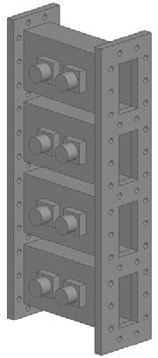
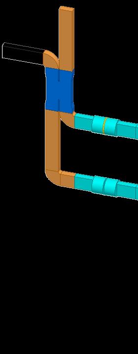
9 3D model for 0.5 MW Prototype PAM antenna Toroidal splitter Poloidal splitter Directional coupler Vacuum port Taper Straight waveguide PAM 330 mm X 2 X 2 X 2


10 Machining and Joint of PAM plate Material : OFHC Cooling line Cutaway view 9 Diffusion bonding Joint surface has the same physical and mechanical properties as the base material. a high quality joints with no discontinuity and porosity in the interface. joining either similar or dissimilar materials. Easy and inexpensive


11 Bonding technology for PAM construction Brazing, Explosive bonding, Welding, Diffusion bonding, etc. PAM in WEST SS Cu Explosive bonding for dissimilar metal joining Limitations Wave height depends of ignition location Copper At 300 mm from the IP At 800 mm from the IP 2700 mm from the IP Stainless steel.6 m m 1 mm 2 mm Available SS Copper Brazing - Leakage of filler material can contaminate the inside of PAM and even can cause arc in high power transmission when it s not properly processed. Diffusion bonding - Solid-state diffusion by applying high pressure at an elevated temperature - Pros: no impurities - Cons: Deformation (or contraction) by pressure 11
![Phase error due to curved surface (X,Y,Z) R1C1/C8 C2/C7 C3/C6 C4/C5 R2C1/C8 C2/C7 C3/C6 C4/C5 X Y Z ΔX ΔΦ R [%] 8.](/docs-images/90/102411922/images/12-3.jpg "48 63 117 8.07 45 117 0.42 2.1 o 0.14% 7.79 27 117 7.66 9 117 0.14 0.71 o 0.015% 1.69 63 39 1.28 45 39 0.41 2.1 o 0.14% 1.")

12 Phase error due to curved surface (X,Y,Z) R1C1/C8 C2/C7 C3/C6 C4/C5 R2C1/C8 C2/C7 C3/C6 C4/C5 X Y Z ΔX ΔΦ R [%] o 0.14% o 0.015% o 0.14% o 0.015% Curved surface of the active waveguide of the launcher. RF 180 R 1-R Plasma 350 mm Passive waveguide ~750 mm Curvature shaping Passive waveguide R

![plasma radiation without cooling 0 0 10 20 30 40 50 60 Time [s] The comparison of the maximum temperatures of the PAM made of copper and stainless steel.](/docs-images/90/102411922/images/13-4.jpg "Thermal analysis based on a simplified model was performed for 60 sec pulse. Temperature change of PAM prototype by the RF loss and plasma radiation without cooling was calculated.")

13 Thermal analysis with a simplified model stainless steel 25 kw/m kw/m Temperature [ o C] Copper Stainless steel 100 kw/m 2 50 kw/m 2 Temperature distribution of prototype PAM made of stainless steel by 60 seconds pulse by 125-kW RF power and plasma radiation without cooling Time [s] The comparison of the maximum temperatures of the PAM made of copper and stainless steel. Thermal analysis based on a simplified model was performed for 60 sec pulse. Temperature change of PAM prototype by the RF loss and plasma radiation without cooling was calculated. The multijunction was divided into three parts in the model. The peak RF loss in each part was adopted as an average RF loss in each to maximize the temperature rise for the conservative calculation. The materials were compared in stainless steel and copper cases. The peak temperature after 60 second RF pulse with 100 kw/m 2 plasma radiation was estimated to be ~ 355 o C and 102 o C at the mouth of the launcher, facing the plasma, made of stainless steel and copper, respectively. Therefore it is possible to operate the prototype PAM without cooling for 500 kw 60 seconds pulse operation. 13
14 Low loss transmission line system %Loss/10m WG radius~57 mm TE01 mode TE11 mode Rect WG Circumference of WG [mm] Comparison of Resistive Loss on the copper waveguide wall depending on the waveguide circumference. TE 11O mode TE 01O mode Easy to make mode converter Polarization can be rotated during propagation. No polarization due to circular symmetric field Extremely low loss in highly oversized WG Complicated to make mode converter Oversized circular waveguide should be used as long as the length of TL > 50 m. It is difficult to lower the loss <5% with rectangular WG. Circular waveguide radius, R R>57 mm: loss of TE 11O > TE O 01 R<57 mm: loss of TE 11O < TE O 01 Resistive loss in the 50-m long circular waveguide with 60 mm radius TE 10 in WR284 TE 01O in 60 mm radius TE 11O in 60 mm radius Material 80 m 50 m Cu 25% 17% Al 32% 21% Cu 5.9% 3.7% Al 7.6% 4.8% Cu 6.6% 4.2% Al 8.5% 5.4% 14
15 Rectangular to circular mode converter is necessary Since the klystron output is TE 10 mode in a WR187 rectangular waveguide, TTEE 1100 to TTEE OO 0000 mode converter is necessary. Two types of mode converters were developed; In-line coupling & sidewall coupling R [mm] Cutoff radius of the several TE and TM mode in a circular waveguide at 5 GHz The radius of circular output of mode converter was chosen to be 40 mm not to excite higher order mode since 10 modes can propagate in a circular waveguide of 60-mm radius. The cutoff radius of TE O 01 mode = 36.6 mm. The R40-to-R60 taper will extend the waveguide size. Mode conversion scheme K K WR187 R40 R40 mode mode converter converter WR187 mode converter R40 Taper R60 Taper R60 In-line coupling (Serpentine) Sidewall coupling 15


![(R40) [Taper] Z p](/docs-images/90/102411922/images/16-10.jpg "2A 487 mm (Radius")

16 RF designs for mode converters Sidewall coupling Poles to supress TE 21 and TM 11 mode In-line coupling S 21 (TE 01 )= db Diffraction loss ~0.6% E norm E max with 500 kw = 9.85 kv/cm TE 10 -TE 11 O WR187-to-R32 TE 11O -TE 01O (R40) [Taper] Z p 2A 487 mm (Radius total length) ~ 1500 mm when R60 S 21 (TE 01 )= db Diffraction loss = 1.4% 16


17 Construction of mode converter mock-ups TE O 10 to TE 11 TE O O 11 to TE 01 Two types of mode converter mock-up were developed and their performances were compared. Since the TE O 01 mode has a circular symmetric field, azimuthal dependence of the transmission through one pair of mode converters were measured. Serpentine mode converter Port 1 Port 2 α α (Serpentine) Sidewall MC, Measure Sidewall coupling mode converter 17


, connecting two")
.")
18 RF measurement of mode converter mock-ups Sidewall coupler has excellent azimuthal symmetry but low S 21 due to surface condition. The serpentine mode converter showed sudden decrease at +/- 80 o. HFSS calculation showed that the poor azimuthal symmetry was due to the length of straight section, 200mm (---), connecting two mode converters. The sudden change disappeared when the length is 300 mm (---). (Serpentine) Sidewall MC, Measure HFSS calculation and experimental measurement showed excellent agreement. 18


19 Refinements for prototype construction Refined design for machining with better performance. Sidewall coupling Perfect conductor boundary, S 21 = db= 99.8% Diffraction Loss = 0.2% Serpentine Z p =115.8 mm, A= 4.4 mm, R=39.5 mm S 21 = db ~ 98.9% Diffraction Loss = 1.1%


20 Prototype is under construction Design of Circular Taper The radius of the mode converter circular output is 40 mm and the radius of the circular waveguide for transmission is 60 mm. R40-R60 taper is necessary for connection. Various shapes of profiles were compared. R40 Linear R60 R40 Two slope linear R60 R40 Arc R60 R40 Parabola R60 R40 Sinusoidal R60 Low diffraction loss for TE 11O mode Sidewall coupling type was adopted as a prototype. TE 01O mode Transmission efficiency with copper is predicted to be 99.5% from the HFSS calculation. Copper boundary S21 = 99.5% Diffraction loss ~0.2% Resistive loss ~ 0.3% 20
21 Summary and Future Work 0.5 MW Prototype PAM is under development. - RF and mechanical design for construction was completed - Diffusion bonding will be used for construction of PAM - No phase correction of curved shape - Cooling on launcher mouth facing the plasma Two types of mode converter mock-ups for TE 01O mode were developed and their characteristics were measured. - Side wall coupling type showed better azimuthal symmetry. - Prototype mode converter adopting sidewall coupling type is under construction. Future work - Manufacturing and installation of PAM - Rigid supporting structure design eddy current by PF swing and plasma disruption, and consequent torque induced on the antenna in conjunction with static magnetic field, etc. - Part of transmission line (~16 m) made of WR284 rectangular waveguide will be changed to oversized circular waveguide made of aluminum, which are lighter and cheaper 21

22 THANK YOU FOR YOUR ATTENTION!! 22


 Cu loss =5.")
23 Circular waveguide 16 m Part of transmission line will be changed to oversized circular waveguide made of aluminum which is cheaper and lighter 16-m WR284( ) Cu loss =5.7% 16-m R60(O) Al loss =1.6%
 WR229 3-dB hybrid splitter E norm 44.7 mm 68.3 mm 50.")


24 HFSS design of multijunction module (N //0 =2.5) WR229 3-dB hybrid splitter E norm 44.7 mm 68.3 mm 50.4 mm WR229 4-way splitter design based on 3-dB hybrid splitter E max = 6.6 kv/cm with 250 kw mm E max ~9 kv/cm with 500 kw mm R40 Linear R60 R40 Two slope linear R60 R40 Arc R60 R40 Parabola R60 R40 Sinusoidal R60 Low diffraction loss for TE 11O mode TE 01O mode
Launcher Study for KSTAR 5 GHz LHCD System*
 Launcher Study for KSTAR 5 GHz LHCD System* Joint Workshop on RF Heating and Current Drive in Fusion Plasmas October 24, 2005 Pohang Accelerator Laboratory, Pohang Y. S. Bae, M. H. Cho, W. Namkung Department
Development Status of KSTAR LHCD System
 Development Status of KSTAR LHCD System September 24, 2004 Y. S. Bae,, M. H. Cho, W. Namkung Plasma Sheath Lab. Department of Physics, Pohang University of Science and Technology LHCD system overview Objectives
National Fusion Research Institute. Pohang, Korea, December 14-16,
 Korea-Japan Workshop on Physics and Technology of Heating and Current Drive Hyunho Wi, Haejin Kim, Sonjong Wang, and Jong-gu Kwak National Fusion Research Institute Pohang, Korea, December 14-16, 2016
3.10 Lower Hybrid Current Drive (LHCD) System
 System") 3.10 Lower Hybrid Current Drive (LHCD) System KUANG Guangli SHAN Jiafang 3.10.1 Purpose of LHCD program 3.10.1.1 Introduction Lower hybrid waves are quasi-static electric waves propagated in magnetically
3.10 Lower Hybrid Current Drive (LHCD) System KUANG Guangli SHAN Jiafang 3.10.1 Purpose of LHCD program 3.10.1.1 Introduction Lower hybrid waves are quasi-static electric waves propagated in magnetically
First Results From the Alcator C-Mod Lower Hybrid Experiment.
 First Results From the Alcator C-Mod Lower Hybrid Experiment. R. Parker 1, N. Basse 1, W. Beck 1, S. Bernabei 2, R. Childs 1, N. Greenough 2, M. Grimes 1, D. Gwinn 1, J. Hosea 2, J. Irby 1, D. Johnson
Lower Hybrid. Ron Parker Alcator C-Mod PAC Meeting January January 2006 Alcator C-Mod PAC Meeting 1
 Lower Hybrid Ron Parker Alcator C-Mod PAC Meeting 25-27 January 2006 25-27 January 2006 Alcator C-Mod PAC Meeting 1 Goal of Lower Hybrid Current Drive Experiments Use Lower Hybrid Current Drive to supplement
Recent progress of 170 GHz Gyrotron in KSTAR
 Recent progress of 170 GHz Gyrotron in KSTAR Japan-Korea Workshop on Physics and Technology of Heating and Current Drive Hanwha Resort, Haeundae, Busan, Korea January 28-30, 2013 J.H. Jeong, M. Joung,
Study of Elliptical Polarization Requirement of KSTAR 84-GHz ECH System
 Journal of the Korean Physical Society, Vol. 49, December 2006, pp. S201 S205 Study of Elliptical Polarization Requirement of KSTAR 84-GHz ECH System Jinhyun Jeong, Youngsoon Bae, Moohyun Cho and Won Namkung
Operational progress of 170GHz 1MW ECH system in KSTAR
 8 th IAEA TM on Steady State Operation of Magnetic Fusion Devices, May. 29, 2015, NARA, JAPAN Operational progress of 170GHz 1MW ECH system in KSTAR J. H. Jeong a, Y. S. Bae a, M. Joung a, M. H. Woo a,
Experimental results and Upgrade plan of ECH/CD system in KSTAR
 2015 KSTAR conference, Feb. 27, 2015, Daejeon, Korea Experimental results and Upgrade plan of ECH/CD system in KSTAR J. H. Jeong a, Y. S. Bae a, M. Joung a, J. W. Han a, I. H. Rhee a, I. H. Rhee a, S.
Diagnostic development to measure parallel wavenumber of lower hybrid waves on Alcator C-Mod
 Diagnostic development to measure parallel wavenumber of lower hybrid waves on Alcator C-Mod S. G. Baek, T. Shinya*, G. M. Wallace, S. Shiraiwa, R. R. Parker, Y. Takase*, D. Brunner MIT Plasma Science
Design and commissioning of a novel LHCD launcher on Alcator C-Mod
 FTP/P6-4 Design and commissioning of a novel LHCD launcher on Alcator C-Mod S. Shiraiwa, O. Meneghini, W. Beck, J. Doody, P. MacGibbon, J. Irby, D. Johnson, P. Koert, C. Lau, R. R. Parker, D. Terry, R.
Design, Development and Testing of RF Window for C band 250 kw CW Power Klystron
 Available online www.ejaet.com European Journal of Advances in Engineering and Technology, 2016, 3(6): 26-30 Research Article ISSN: 2394-658X Design, Development and Testing of RF Window for C band 250
Recent Progress on Lower Hybrid Current Drive and Implications for ITER
 Recent Progress on Lower Hybrid Current Drive and Implications for ITER J. Hillairet 1, A. Ekedahl 1,7, M. Goniche 1, Y.S. Bae 2, J. Achard 1, A. Armitano 1, B.Beckett 6, J.Belo 3, G. Berger-By 1, J.M.
Helicon Wave Current Drive in KSTAR Plasmas
 Daejeon Helicon Wave Current Drive in KSTAR Plasmas S. J. Wanga, H. J. Kima, Jeehyun Kima, V. Vdovinb, B. H. Parka, H. H. Wic, S. H. Kimd, and J. G. Kwaka anational Fusion Research Institute, Daejeon,
Advanced Tokamak Program and Lower Hybrid Experiment. Ron Parker MIT Plasma Science and Fusion Center
 Advanced Tokamak Program and Lower Hybrid Experiment Ron Parker MIT Plasma Science and Fusion Center Alcator C-Mod Program Advisory Meeting 23-24 February 2004 Main Goals of the Alcator C-Mod AT Program
PERFORMANCE OF THE 110 GHz SYSTEM ON THE DIII D TOKAMAK
 GA A23714 PERFORMANCE OF THE 110 GHz SYSTEM ON THE DIII D TOKAMAK by J. LOHR, R.W. CALLIS, W.P. CARY, I.A. GORELOV, R.A. LEGG, R.I. PINSKER, and D. PONCE JULY 2001 This report was prepared as an account
Couplers for Project X. S. Kazakov, T. Khabiboulline
 Couplers for Project X S. Kazakov, T. Khabiboulline TTC meeting on CW-SRF, 2013 Requirements to Project X couplers Cavity SSR1 (325MHz): Cavity SSR2 (325MHz): Max. energy gain - 2.1 MV, Max. power, 1 ma
RF Physics: Status and Plans
 RF Physics: Status and Plans Program Advisory Committee meeting February 6-7, 2002 S. J. Wukitch Outline: 1. Overview of RF Physics issues 2. Review of antenna performance and near term modifications.
Heating Issues. G.Granucci on behalf of the project team
 Heating Issues G.Granucci on behalf of the project team EURO fusion DTT Workshop Frascati, Italy, 19-20 June 2017 Summary Physical Requirements DTT Heating Mix ECRH System ICRH System Auxiliary Heating
GA A26150 PROGRESS ON DESIGN AND TESTING OF CORRUGATED WAVEGUIDE COMPONENTS SUITABLE FOR ITER ECH AND CD TRANSMISSION LINES
 GA A26150 PROGRESS ON DESIGN AND TESTING OF CORRUGATED WAVEGUIDE COMPONENTS SUITABLE FOR ITER ECH AND CD TRANSMISSION LINES by R.A. OLSTAD, R.W. CALLIS, J.L. DOANE, H.J. GRUNLOH, and C.P. MOELLER JUNE
High Field Side Lower Hybrid Current Drive Launcher Design for DIII-D
 High Field Side Lower Hybrid Current Drive Launcher Design for DIII-D by G.M. Wallace (MIT PSFC) Presented at the American Physical Society Division of Plasma Physics Annual Meeting October 23, 2017 On
Development of the 170GHz gyrotron and equatorial launcher for ITER
 Development of the 17GHz gyrotron and equatorial launcher for ITER K.Sakamoto, A. Kasugai, K. Takahashi, R. Minami a), T. Kariya b), Y. Mitsunaka b), N.Kobayashi Plasma Heating Laboratory, Japan Atomic
National Fusion Research Institute a. Princeton Plasma Physics Laboratory
 Ko-Ja Workshop on Physics and Technology of Heating and Current Drive, Pohang, Korea, 2016 M. Joung, J. H. Jeong, J. W. Han, I. H. Lee, S. K. Kim, S. J. Wang, J. G. Kwak, R. Ellis a, J. Hosea a and the
Estimation of the Loss in the ECH Transmission Lines for ITER
 Estimation of the Loss in the ECH Transmission Lines for ITER S. T. Han, M. A. Shapiro, J. R. Sirigiri, D. Tax, R. J. Temkin and P. P. Woskov MIT Plasma Science and Fusion Center, MIT Building NW16-186,
Electromagnetic Field Simulation for ICRF Antenna and Comparison with Experimental Results in LHD
 Electromagnetic Field Simulation for ICRF Antenna and Comparison with Experimental Results in LHD Takashi MUTOH, Hiroshi KASAHARA, Tetsuo SEKI, Kenji SAITO, Ryuhei KUMAZAWA, Fujio SHIMPO and Goro NOMURA
KSTAR ICRF transmission line system upgrade for load resilient operation
 KSTAR ICRF transmission line system upgrade for load resilient operation H. J. Kim, S. J. Wang, Y. S. Bae, H. L. Yang, J.-G. Kwak, S. H. Kim a and M. Park a KSTAR Research Center, NFRI a Fusion Plasma
P. Koert, P. MacGibbon, R. Vieira, D. Terry, R.Leccacorvi, J. Doody, W. Beck. October 2008
 PSFC/JA-08-50 WAVEGUIDE SPLITTER FOR LOWER HYBRID CURRENT DRIVE P. Koert, P. MacGibbon, R. Vieira, D. Terry, R.Leccacorvi, J. Doody, W. Beck October 2008 Plasma Science and Fusion Center Massachusetts
GA A26816 DESIGNS OF NEW COMPONENTS FOR ITER ECH&CD TRANSMISSION LINES
 GA A26816 DESIGNS OF NEW COMPONENTS FOR ITER ECH&CD TRANSMISSION LINES by R.A. OLSTAD, J.L. DOANE, C.P. MOELLER and C.J. MURPHY JULY 2010 DISCLAIMER This report was prepared as an account of work sponsored
Non-inductive Production of Extremely Overdense Spherical Tokamak Plasma by Electron Bernstein Wave Excited via O-X-B Method in LATE
 1 EXW/P4-4 Non-inductive Production of Extremely Overdense Spherical Tokamak Plasma by Electron Bernstein Wave Excited via O-X-B Method in LATE H. Tanaka, M. Uchida, T. Maekawa, K. Kuroda, Y. Nozawa, A.
Design study for JT-60SA ECRF system and the latest results of JT-60U ECRF system
 Japan-Korea : Workshop on Physics of Wave Heating and Current Drive, NFRI, Daejon, Korea, Jan. 14-15, 2008 R F &LHRF& ECRF ICRF JT - 60 JT-60 RF group Japan Atomic Energy Agency Design study for JT-60SA
GA A25793 CW OPERATION OF CORRUGATED WAVEGUIDE TRANSMISSION LINES FOR ITER ECH AND CD SYSTEM
 GA A25793 TRANSMISSION LINES FOR ITER ECH AND CD SYSTEM by R.A. OLSTAD, R.W. CALLIS, J.L. DOANE, H.J. GRUNLOH, and C.P. MOELLER MAY 2007 DISCLAIMER This report was prepared as an account of work sponsored
J.Shafii, J.N. Talmadge, R.J. Vernon, HSX team HSX Plasma Laboratory, University of Wisconsin-Madison T. S. Bigelow, ORNL K.M.
 J.Shafii, J.N. Talmadge, R.J. Vernon, HSX team HSX Plasma Laboratory, University of Wisconsin-Madison T. S. Bigelow, ORNL K.M. Likin, Fusion Division, CIEMAT Outline Abstract HSX ECH system Introduction
Polarization-controllable TE 21 mode converter
 REVIEW OF SCIENTIFIC INSTRUMENTS 76, 074703 2005 Polarization-controllable TE 21 mode converter T. H. Chang, C. F. Yu, and C. T. Fan Department of Physics, National Tsing Hua University, Hsinchu, Taiwan
30 GHz rf components for CTF3 (and CLIC) next part. I. Syratchev
 next part. I. Syratchev") 3 GHz rf components for CTF3 (and CLIC) next part I. Syratchev 3 GHz overmoded waveguide components (GYCOM, Russia) Mode converter 4.86x5 Taper Mitered bend.75.5 T 5 9.985 Measured losses per mode converter
3 GHz rf components for CTF3 (and CLIC) next part I. Syratchev 3 GHz overmoded waveguide components (GYCOM, Russia) Mode converter 4.86x5 Taper Mitered bend.75.5 T 5 9.985 Measured losses per mode converter
2. Achievement of reliable long pulse operation of 1 MW 170 GHz gyrotron
 Demonstration of 1 MW quasi-cw operation of 170 GHz Gyrotron and Progress of EC Technology for ITER A.Kasugai, K.Sakamoto, K.Takahashi, K.Kajiwara, Y.Oda, N.Kobayashi Fusion Research and Development Directorate,
A DUAL-PORTED, DUAL-POLARIZED SPHERICAL NEAR-FIELD PROBE
 A DUAL-PORTED, DUAL-POLARIZED SPHERICAL NEAR-FIELD PROBE by J. R. Jones and D. P. Hardin Scientific-Atlanta, Inc. Spherical near-field testing of antennas requires the acquisition of a great volume of
Field Aligned ICRF Antenna Design for EAST *
 Field Aligned ICRF Antenna Design for EAST * S.J. Wukitch 1, Y. Lin 1, C. Qin 2, X. Zhang 2, W. Beck 1, P. Koert 1, and L. Zhou 1 1) MIT Plasma Science and Fusion Center, Cambridge, MA USA. 2) Institute
Abstract. G.D. Garstka 47 th APS-DPP Denver October 27, Pegasus Toroidal Experiment University of Wisconsin-Madison
 Abstract The PEGASUS Toroidal Experiment provides an attractive opportunity for investigating the physics and implementation of electron Bernstein wave (EBW) heating and current drive in an overdense ST
RF Heating and Current Drive in the JT-60U Tokamak
 KPS Meeting, ct. 22 25, Chonju RF Heating and Current Drive in the JT-6U Tokamak presented by T. Fujii Japan Atomic Energy Agency Outline JT-6U 1. JT-6U Tokamak Device and its Objectives 2. LHRF Current
REVIEW OF HIGH POWER CW COUPLERS FOR SC CAVITIES. S. Belomestnykh
 REVIEW OF HIGH POWER CW COUPLERS FOR SC CAVITIES S. Belomestnykh HPC workshop JLAB, 30 October 2002 Introduction Many aspects of the high-power coupler design, fabrication, preparation, conditioning, integration
Overview of ICRF Experiments on Alcator C-Mod*
 49 th annual APS-DPP meeting, Orlando, FL, Nov. 2007 Overview of ICRF Experiments on Alcator C-Mod* Y. Lin, S. J. Wukitch, W. Beck, A. Binus, P. Koert, A. Parisot, M. Reinke and the Alcator C-Mod team
ICRF Physics in KSTAR Steady State
 ICRF Physics in KSTAR Steady State Operation (focused on the base line operation) Oct. 24, 2005 Jong-gu Kwak on the behalf of KSTAR ICRF TEAM Korea Atomic Energy Research Institute Contents Roles of ICRF
Dinesh Micro Waves & Electronics
 Wave Guide Components RECTANGULAR WAVE GUDES Dinesh Microwaves and Electronics manufacturers of high power waveguide in the microwaves industry, this experience had resulted in designing, manufacturing
ELEC4604. RF Electronics. Experiment 2
 ELEC4604 RF Electronics Experiment MICROWAVE MEASUREMENT TECHNIQUES 1. Introduction and Objectives In designing the RF front end of a microwave communication system it is important to appreciate that the
H. Y. Lee, J. W. Lee, J. G. Jo, J. Y. Park, S. C. Kim, J. I. Wang, J. Y. Jang, S. H. Kim, Y. S. Na, Y. S. Hwang
 Study on EBW assisted start-up and heating experiments via direct XB mode conversion from low field side injection in VEST H. Y. Lee, J. W. Lee, J. G. Jo, J. Y. Park, S. C. Kim, J. I. Wang, J. Y. Jang,
SOL Reflectometer for Alcator C-Mod
 Alcator C-Mod SOL Reflectometer for Alcator C-Mod C. Lau 1 G. Hanson 2, J. B. Wilgen 2, Y. Lin 1, G. Wallace 1, and S. J. Wukitch 1 1 MIT Plasma Science and Fusion Center, Cambridge, MA 02139 2 Oak Ridge
HIGH-POWER CORRUGATED WAVEGUIDE COMPONENTS FOR mm-wave FUSION HEATING SYSTEMS
 GA A22466 HIGH-POWER CORRUGATED WAVEGUIDE COMPONENTS FOR mm-wave FUSION HEATING SYSTEMS by R.A. OLSTAD, J.L. DOANE, C.P. MOELLER, R.C. O NEILL, and M. Di MARTINO OCTOBER 1996 GA A22466 HIGH-POWER CORRUGATED
The transition for the Elettra Input Power Coupler to the standard WR1800
 The transition for the Elettra Input Power Coupler to the standard WR1800 Cristina Pasotti, Mauro Bocciai, Luca Bortolossi, Alessandro Fabris, Marco Ottobretti, Mauro Rinaldi Alessio Turchet Sincrotrone
Structural Analysis of High-field-Side RF antennas during a disruption on the Advanced Divertor experiment (ADX)
") Structural Analysis of High-field-Side RF antennas during a disruption on the Advanced Divertor experiment (ADX) J. Doody, B. LaBombard, R. Leccacorvi, S. Shiraiwa, R. Vieira, G.M. Wallace, S.J. Wukitch,
Structural Analysis of High-field-Side RF antennas during a disruption on the Advanced Divertor experiment (ADX) J. Doody, B. LaBombard, R. Leccacorvi, S. Shiraiwa, R. Vieira, G.M. Wallace, S.J. Wukitch,
IAEA-CN-94/FT/2-2 Test Results on Systems Developed for SST-1 Tokamak
 Test Results on Systems Developed for SST-1 Tokamak D. Bora, and SST-1 TEAM Institute for Plasma Research, Bhat, Gandhinagar 382 428, INDIA e-mail: dbora@ipr.res.in Abstract. Steady state Superconducting
Status of the rf Current Drive Systems on MST
 Status of the rf Current Drive Systems on MST John A. Goetz for A. Almagri, J.K. Anderson, D.R. Burke, M.M. Clark, W.A. Cox, C.B. Forest, R. Ganch, M.C. Kaufman, J.G. Kulpin, P. Nonn, R. O Connell, S.P.
GA A22776 THE DESIGN AND PERFORMANCE OF WAVEGUIDE TRANSMISSION LINE COMPONENTS FOR PLASMA ELECTRON CYCLOTRON HEATING (ECH) SYSTEMS
 SYSTEMS") GA A22776 THE DESIGN AND PERFORMANCE OF WAVEGUIDE TRANSMISSION LINE COMPONENTS FOR PLASMA ELECTRON CYCLOTRON HEATING (ECH) SYSTEMS by R.C. O Neill, J.L. Doane, C.P. Moeller, M. DiMartino, H.J. Grunloh,
GA A22776 THE DESIGN AND PERFORMANCE OF WAVEGUIDE TRANSMISSION LINE COMPONENTS FOR PLASMA ELECTRON CYCLOTRON HEATING (ECH) SYSTEMS by R.C. O Neill, J.L. Doane, C.P. Moeller, M. DiMartino, H.J. Grunloh,
Installation of 84-GHz, 500-kW KSTAR ECH system
 Korea Superconducting Tokamak Advanced Research Sample image2 Sample image3 Installation of 84-GHz, 500-kW KSTAR ECH system 정진현, 박승일, 조무현, 남궁원포항공과대학교 배영순, 한원순, 안상진국가핵융합연구소 2007 년도한국물리학회추계학술논문발표회 October
High Power, Magnet-free, Waveguide Based Circulator Using Angular-Momentum Biasing of a Resonant Ring
 SLAC-R-1080 High Power, Magnet-free, Waveguide Based Circulator Using Angular-Momentum Biasing of a Resonant Ring Jeffrey Neilson and Emilio Nanni August 18, 2017 Prepared for Calabazas Creek Research,
Recent Activities on SST-1 and ADITYA-U Tokamaks )
") Recent Activities on SST-1 and ADITYA-U Tokamaks ) Promod K. SHARMA 1,2), Yogesh M. JAIN 1,2), Kiran K. AMBULKAR 1),PramodR.PARMAR 1), Chetan G. VIRANI 1), Saifali DALAKOTI 1), Jagabandhu KUMAR 1), Arvind
Recent Activities on SST-1 and ADITYA-U Tokamaks ) Promod K. SHARMA 1,2), Yogesh M. JAIN 1,2), Kiran K. AMBULKAR 1),PramodR.PARMAR 1), Chetan G. VIRANI 1), Saifali DALAKOTI 1), Jagabandhu KUMAR 1), Arvind
High Power 12-Element Triangular-Grid Rectangular Radial Line Helical Array Antenna
 Progress In Electromagnetics Research C, Vol. 55, 17 24, 2014 High Power 12-Element Triangular-Grid Rectangular Radial Line Helical Array Antenna Xiang-Qiang Li *, Qing-Xiang Liu, and Jian-Qiong Zhang
Summary of Research Activities on Microwave Discharge Phenomena involving Chalmers (Sweden), Institute of Applied Physics (Russia) and CNES (France)
, Institute of Applied Physics (Russia) and CNES (France)") Summary of Research Activities on Microwave Discharge Phenomena involving Chalmers (Sweden), Institute of Applied Physics (Russia) and CNES (France) J. Puech (1), D. Anderson (2), M.Lisak (2), E.I. Rakova
Summary of Research Activities on Microwave Discharge Phenomena involving Chalmers (Sweden), Institute of Applied Physics (Russia) and CNES (France) J. Puech (1), D. Anderson (2), M.Lisak (2), E.I. Rakova
R.K.YADAV. 2. Explain with suitable sketch the operation of two-cavity Klystron amplifier. explain the concept of velocity and current modulations.
 Question Bank DEPARTMENT OF ELECTRONICS AND COMMUNICATION SUBJECT- MICROWAVE ENGINEERING(EEC-603) Unit-III 1. What are the high frequency limitations of conventional tubes? Explain clearly. 2. Explain
ECRH on the Levitated Dipole Experiment
 ECRH on the Levitated Dipole Experiment S. Mahar, J. Kesner, A.C. Boxer, J.E. Ellsworth, I. Karim, A. Roach MIT PSFC A.K. Hansen, D.T. Garnier, M.E. Mauel, E.E.Ortiz Columbia University Presented at the
Toroidal Rotation and Ion Temperature Validations in KSTAR Plasmas
 Toroidal Rotation and Ion Temperature Validations in KSTAR Plasmas S. G. Lee 1, H. H. Lee 1, W. H. Ko 1, J. W. Yoo 2, on behalf of the KSTAR team and collaborators 1 NFRI, Daejeon, Korea 2 UST, Daejeon,
Novel Vacuum Vessel & Coil System Design for the Advanced Divertor Experiment (ADX)
") Novel Vacuum Vessel & Coil System Design for the Advanced Divertor Experiment (ADX) R.F. Vieira, J. Doody, W.K. Beck, L. Zhou, R. Leccacorvi, B. LaBombard, R.S. Granetz, S.M. Wolfe, J.H. Irby, S.J. Wukitch,
Novel Vacuum Vessel & Coil System Design for the Advanced Divertor Experiment (ADX) R.F. Vieira, J. Doody, W.K. Beck, L. Zhou, R. Leccacorvi, B. LaBombard, R.S. Granetz, S.M. Wolfe, J.H. Irby, S.J. Wukitch,
Conditioning and High Power Operation of the Lower Hybrid Current Drive Launcher in JET
 JET P(97)19 Conditioning and High Power Operation of the Lower Hybrid Current Drive Launcher in JET A Ekedahl 1 J A Dobbing P Finburg P Froissard C Gormezano M Lennholm F Rimini P Schild F X Söldner. JET
Development of a 20-MeV Dielectric-Loaded Accelerator Test Facility
 SLAC-PUB-11299 Development of a 20-MeV Dielectric-Loaded Accelerator Test Facility S.H. Gold, et al. Contributed to 11th Advanced Accelerator Concepts Workshop (AAC 2004), 06/21/2004--6/26/2004, Stony
(i) Determine the admittance parameters of the network of Fig 1 (f) and draw its - equivalent circuit.
 Determine the admittance parameters of the network of Fig 1 (f) and draw its - equivalent circuit.") I.E.S-(Conv.)-1995 ELECTRONICS AND TELECOMMUNICATION ENGINEERING PAPER - I Some useful data: Electron charge: 1.6 10 19 Coulomb Free space permeability: 4 10 7 H/m Free space permittivity: 8.85 pf/m Velocity
I.E.S-(Conv.)-1995 ELECTRONICS AND TELECOMMUNICATION ENGINEERING PAPER - I Some useful data: Electron charge: 1.6 10 19 Coulomb Free space permeability: 4 10 7 H/m Free space permittivity: 8.85 pf/m Velocity
Design and Testing of RF Window for a High Power Klystron
 Available online www.ejaet.com European Journal of Advances in Engineering and Technology, 2014, 1(2): 29-34 Research Article ISSN: 2394-658X Design and Testing of RF Window for a High Power Klystron D
Dinesh Micro Waves & Electronics
 MICROWAVE TRAINING KITS Dinesh Microwaves and Electronics manufacturers of three centimeter waveguidetraining system to provide users an in depth training on microwave waveguide device. The training kit
2.2 MW Operation of the European Coaxial-Cavity Pre-Prototype Gyrotron for ITER
 2.2 MW Operation of the European Coaxial-Cavity Pre-Prototype Gyrotron for ITER G. Gantenbein 1, T. Rzesnicki 1, B. Piosczyk 1, S. Kern 1, S. Illy 1, J. Jin 1, A. Samartsev 1, A. Schlaich 1,2 and M. Thumm
EC6011-ELECTROMAGNETICINTERFERENCEANDCOMPATIBILITY
 EC6011-ELECTROMAGNETICINTERFERENCEANDCOMPATIBILITY UNIT-3 Part A 1. What is an opto-isolator? [N/D-16] An optoisolator (also known as optical coupler,optocoupler and opto-isolator) is a semiconductor device
High Power Antenna Design for Lower Hybrid Current Drive in MST
 High Power Antenna Design for Lower Hybrid Current Drive in MST M.A. Thomas, J.A. Goetz, M.C. Kaufman, S.P. Oliva University of WisconsinMadison J.B.O. Caughman, P.M. Ryan Oak Ridge National Laboratory
AN IN-LINE POWER MONITOR FOR HE11 LOW LOSS TRANSMISSION LINES
 GA A24757 AN IN-LINE POWER MONITOR FOR HE11 LOW LOSS TRANSMISSION LINES by R.W. CALLIS, J. LOHR, I.A. GORELOV, K. KAJIWARA, D. PONCE, J.L. DOANE, J.F. TOOKER JUNE 2004 QTYUIOP DISCLAIMER This report was
Aperture Antennas. Reflectors, horns. High Gain Nearly real input impedance. Huygens Principle
 Antennas 97 Aperture Antennas Reflectors, horns. High Gain Nearly real input impedance Huygens Principle Each point of a wave front is a secondary source of spherical waves. 97 Antennas 98 Equivalence
RF Design of Normal Conducting Deflecting Cavity
 RF Design of Normal Conducting Deflecting Cavity Valery Dolgashev (SLAC), Geoff Waldschmidt, Ali Nassiri (Argonne National Laboratory, Advanced Photon Source) 48th ICFA Advanced Beam Dynamics Workshop
A HIGH-POWER LOW-LOSS MULTIPORT RADIAL WAVEGUIDE POWER DIVIDER
 Progress In Electromagnetics Research Letters, Vol. 31, 189 198, 2012 A HIGH-POWER LOW-LOSS MULTIPORT RADIAL WAVEGUIDE POWER DIVIDER X.-Q. Li *, Q.-X. Liu, and J.-Q. Zhang School of Physical Science and
Design and realization of tracking feed antenna system
 Design and realization of tracking feed antenna system S. H. Mohseni Armaki 1, F. Hojat Kashani 1, J. R. Mohassel 2, and M. Naser-Moghadasi 3a) 1 Electrical engineering faculty, Iran University of science
Measurements of Mode Converted ICRF Waves with Phase Contrast Imaging in Alcator C-Mod
 Measurements of Mode Converted ICRF Waves with Phase Contrast Imaging in Alcator C-Mod N. Tsujii, M. Porkolab, E.M. Edlund, L. Lin, Y. Lin, J.C. Wright, S.J. Wukitch MIT Plasma Science and Fusion Center
Reflectometry for density and fluctuation measurement on EAST
 Reflectometry for density and fluctuation measurement on EAST *, Shoubiao Zhang, Fei Wen, Hao Qu, Yumin Wang, Xiang Han, Defeng Kong, Xiang Gao and EAST contributor Institute of Plasma Physics, Chinese
Status of the HOM Damped Cavity Project
 Status of the HOM Damped Cavity Project E. Weihreter / BESSY for the HOM Damped Cavity Collaboration BESSY, Daresbury Lab, DELTA, MaxLab, NTHU Project funded by the EC under contract HPRI-CT-1999-50011
3. (a) Derive an expression for the Hull cut off condition for cylindrical magnetron oscillator. (b) Write short notes on 8 cavity magnetron [8+8]
![3. (a) Derive an expression for the Hull cut off condition for cylindrical magnetron oscillator. (b) Write short notes on 8 cavity magnetron [8+8]](/thumbs/73/68588725.jpg "3. (a) Derive an expression for the Hull cut off condition for cylindrical magnetron oscillator. (b) Write short notes on 8 cavity magnetron [8+8]") Code No: RR320404 Set No. 1 1. (a) Compare Drift space bunching and Reflector bunching with the help of Applegate diagrams. (b) A reflex Klystron operates at the peak of n=1 or 3 / 4 mode. The dc power
Code No: RR320404 Set No. 1 1. (a) Compare Drift space bunching and Reflector bunching with the help of Applegate diagrams. (b) A reflex Klystron operates at the peak of n=1 or 3 / 4 mode. The dc power
High Gradient Studies at the NLC Test Accelerator (NLCTA)
") Chris Adolphsen High Gradient Studies at the NLC Test Accelerator (NLCTA) NLCTA Linac RF Unit (One of Two) Contributors C. Adolphsen, G. Bowden, D. Burke, J. Cornuelle, S. Dobert, V. Dolgashev, J. Frisch,
Chris Adolphsen High Gradient Studies at the NLC Test Accelerator (NLCTA) NLCTA Linac RF Unit (One of Two) Contributors C. Adolphsen, G. Bowden, D. Burke, J. Cornuelle, S. Dobert, V. Dolgashev, J. Frisch,
A Modular Commercial Tokamak Reactor with Day Long Pulses
 PFC/JA-82-217 A Modular Commercial Tokamak Reactor with Day Long Pulses L. Bromberg, D.R. Cohn, and J.E. C. Williams Massachusetts Institute of Technology Cambridge, Massachusetts 02139 Journal of Fusion
Normal-conducting high-gradient rf systems
 Normal-conducting high-gradient rf systems Introduction Motivation for high gradient Order of 100 GeV/km Operational and state-of-the-art SwissFEL C-band linac: Just under 30 MV/m CLIC prototypes: Over
Ka-BAND KLOPFENSTEIN TAPERED IMPEDANCE TRANSFORMER FOR RADAR APPLICATIONS
 Progress In Electromagnetics Research C, Vol. 27, 253 263, 2012 Ka-BAND KLOPFENSTEIN TAPERED IMPEDANCE TRANSFORMER FOR RADAR APPLICATIONS L. Resley and H. Song * Department of Electrical and Computer Engineering,
Testing of ITER-Class ECH Transmission Line Components at the JAEA Radio-Frequency Test Stand
 1 Testing of ITER-Class ECH Transmission Line Components at the JAEA Radio-Frequency Test Stand R.W. Callis 1, J.L. Doane 1, H.J. Grunloh 1, K. Kajiwara 2, A. Kasugai 2, C.P. Moeller 1, Y. Oda 2, R.A.
Status and Plans for the 805 MHz Box Cavity MuCool RF Workshop III 07/07/09 Al Moretti
 Status and Plans for the 805 MHz Box Cavity MuCool RF Workshop III 07/07/09 Al Moretti 7/6/2009 1 Outline : Description of the Box cavity Concept. Box Cavity Summary Plans. HFSS Models of orthogonal and
2 Theory of electromagnetic waves in waveguides and of waveguide components
 RF transport Stefan Choroba DESY, Hamburg, Germany Abstract This paper deals with the techniques of transport of high-power radiofrequency (RF) power from a RF power source to the cavities of an accelerator.
Plasma Confinement by Pressure of Rotating Magnetic Field in Toroidal Device
 1 ICC/P5-41 Plasma Confinement by Pressure of Rotating Magnetic Field in Toroidal Device V. Svidzinski 1 1 FAR-TECH, Inc., San Diego, USA Corresponding Author: svidzinski@far-tech.com Abstract: Plasma
A DUAL-PORTED PROBE FOR PLANAR NEAR-FIELD MEASUREMENTS
 A DUAL-PORTED PROBE FOR PLANAR NEAR-FIELD MEASUREMENTS W. Keith Dishman, Doren W. Hess, and A. Renee Koster ABSTRACT A dual-linearly polarized probe developed for use in planar near-field antenna measurements
First experiments in H-mode plasmas with the Passive-Active Multijunction (PAM) LHCD launcher in HL-2A and impact on pedestal instabilities
 LHCD launcher in HL-2A and impact on pedestal instabilities") First experiments in H-mode plasmas with the Passive-Active Multijunction (PAM) LHCD launcher in HL-2A and impact on pedestal instabilities A. Ekedahl 1, X.Y. Bai 2, B. Lu 2, R. Magne 1, G.L. Xiao 2,3,
First experiments in H-mode plasmas with the Passive-Active Multijunction (PAM) LHCD launcher in HL-2A and impact on pedestal instabilities A. Ekedahl 1, X.Y. Bai 2, B. Lu 2, R. Magne 1, G.L. Xiao 2,3,
New SLED 3 system for Multi-mega Watt RF compressor. Chen Xu, Juwen Wang, Sami Tantawi
 New SLED 3 system for Multi-mega Watt RF compressor Chen Xu, Juwen Wang, Sami Tantawi SLAC National Accelerator Laboratory, Stanford University, Stanford, CA 94309, USA Electronic address: chenxu@slac.stanford.edu
Christopher Nantista ISG-X SLAC June 17, 2003
 Christopher Nantista ISG-X SLAC June 17, 2003 8-Pack Phase II NLC/JGLC R2 requirement: a linac subunit test rf power distribution dual-moded SLED-II eight 60cm structures Goals: Transport several hundred
GA MICROWAVE WINDOW DEVELOPMENT
 P GA421874 e a MILESTONE NO. 1 TASK ID NOS. T243 (U.S. task 3.2) and T242 (JA Task 2.1) GA MICROWAVE WINDOW DEVELOPMENT by C.P. MOELLER, General Atomics A. KASUGAI, K. SAKAMOTO, and K. TAKAHASHI, Japan
High Power S-Band RF Load for SLAC Linac. A. Krasnykh, F-J Decker, et al. SLAC 2014
 High Power S-Band RF Load for SLAC Linac A. Krasnykh, F-J Decker, et al. SLAC 2014 The LCLS Injector showed the phase jitters (PJ) at L0A, L0B, and L1S stations on beginning of injector setup. Initial
LE/ESSE Payload Design
 LE/ESSE4360 - Payload Design 4.3 Communications Satellite Payload - Hardware Elements Earth, Moon, Mars, and Beyond Dr. Jinjun Shan, Professor of Space Engineering Department of Earth and Space Science
GA A22963 RECENT DEVELOPMENTS ON THE HIGH POWER ECH INSTALLATION AT THE DIII D TOKAMAK
 GA A22963 RECENT DEVELOPMENTS ON THE HIGH POWER ECH INSTALLATION by J. LOHR, D. PONCE, R.W. CALLIS, J.L. DOANE, H. IKEZI, and C.P. MOELLER SEPTEMBER 1998 This report was prepared as an account of work
K band Focal Plane Array: Mechanical and Cryogenic Considerations Steve White,Bob Simon, Mike Stennes February 20, 2008 COLD ELECTRONICS
 K band Focal Plane Array: Mechanical and Cryogenic Considerations Steve White,Bob Simon, Mike Stennes February 20, 2008 CRYOGENICS AND DEWAR DESIGN The dewar outside dimension must be less than the 36
TOPIC 2 WAVEGUIDE AND COMPONENTS
 TOPIC 2 WAVEGUIDE AND COMPONENTS COURSE LEARNING OUTCOME (CLO) CLO1 Explain clearly the generation of microwave, the effects of microwave radiation and the propagation of electromagnetic in a waveguide
NEW OPPORTUNITIES IN VACUUM ELECTRONICS USING PHOTONIC BAND GAP STRUCTURES
 NEW OPPORTUNITIES IN VACUUM ELECTRONICS USING PHOTONIC BAND GAP STRUCTURES J. R. Sirigiri, C. Chen, M. A. Shapiro, E. I. Smirnova, and R. J. Temkin Plasma Science and Fusion Center Massachusetts Institute
The Next Linear Collider Test Accelerator s RF Pulse Compression and Transmission Systems
 SLAC-PUB-7247 February 1999 The Next Linear Collider Test Accelerator s RF Pulse Compression and Transmission Systems S. G. Tantawi et al. Presented at the 5th European Particle Accelerator Conference
A design method of optimized impedance transformer for the ICRF antenna in LHD
 A design method of optimized impedance transformer for the ICRF antenna in LHD Kenji SAITO, Tetsuo SEKI, Hiroshi KASAHARA, Ryosuke SEKI, Ryuhei KUMAZAWA, Goro NOMURA, Fujio SHIMPO, Takashi MUTOH National