Table of Contents. (cont d) User's Guide 1
|
|
|
- Wilfrid Gray
- 6 years ago
- Views:
Transcription
1
2 Table of Contents ELECTRICALC PRO...3 GETTING STARTED...4 KEY DEFINITIONS...4 Basic Function Keys...4 Mode Set-up Keys...5 Electrical Keys...6 Motor Keys...8 Wire Sizing Keys...9 Voltage Drop Keys Grounding Conductor Keys...12 Fuse/Breaker Keys...13 Conduit Sizing Keys...15 PREFERENCE SETTINGS...18 BASIC MATH OPERATIONS...19 PERCENT CALCULATIONS...19 MEMORY OPERATIONS...19 Using M Using Memory Storage Keys (M1- M9)...20 using the electricalc pro...21 KIRCHHOFF S LAW...21 Finding Voltage...21 Finding Amps...22 Finding Current Load...22 Finding Amps From Kilowatts...23 Finding Volt-Amps...23 Finding kva Rating...24 Finding Wattage...24 Finding kw Rating...25 OHM S LAW...26 Finding Volts...26 Finding Amps...26 Finding Resistance (Ohms)...27 MOTOR functions...27 Finding Single-Phase Full-Load Current...28 Finding Motor Wire Size and Ampacity...28 Finding Synchronous Motor Horsepower...29 Finding Direct Current Motor Horsepower...30 (cont d) User's Guide 1
3 (cont d) AMPACITY WIRE SIZING...30 Wire Sizing Based on Insulation Rating...31 Re-Sizing Wire Based on Different Insulation Ratings...32 Wire Sizing Based on Ambient Temperature...32 Wire Sizing Based on Material Type...34 Sizing Parallel Conductors...35 Finding Derated Wire Size...36 Sizing Temperature-Adjusted Derated Wires...36 VOLTAGE DROP...38 Finding Single-Phase Voltage Drop...38 Finding Three-Phase Voltage Drop...39 Finding Voltage Drop Wire Size...40 Finding Voltage Drop Distance...41 Finding Voltage Drop Resistance...43 GROUND CONDUCTOR WIRE SIZE...44 EQUIPMENT GROUNDING COUNDUCTOR WIRE SIZE...45 FUSE AND CIRCUIT BREAKER SIZE...45 STARTER SIZE...47 OVERLOAD PROTECTION SIZE...47 CONDUIT SIZE...48 Finding Motor Branch-Circuit Wire Size and Conduit Size Same Wire Type and Size...49 Finding Conduit Sizes For Multiple Conductors Same Wire Type and Size...50 Finding Number of Wires in Existing Conduit Same Size, Various Types...51 Finding Conduit Size Multiple Conductors, Different Wire Sizes and Types...52 CONVERTING KILOWATT-HOUR AND BTU...53 PARALLEL RESISTANCE...54 APPENDIX A DEFAULT SETTINGS...55 APPENDIX B preference settings...56 APPENDIX C 2014 NEC REFERENCES...57 APPENDIX D CARE INSTRUCTIONS...57 APPENDIX E ACCURACY/ERRORS, AUTO SHUT-OFF, BATTERIES, RESET...58 Repair and Return...60 Warranty ElectriCalc Pro
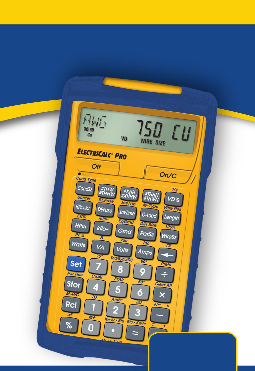
4 ELECTRICALC PRO The ElectriCalc Pro is an invaluable calculator for today s busy electrical professional. Unlike a regular calculator, it has intuitively labeled electrical keys and conforms to the 2014 (and 2011, 2008, 2005, 2002, 1999, 1996) and future National Electrical Codes, allowing you to solve Code-related problems quickly and accurately. The most common NEC tables are now at your fingertips! An important feature of the ElectriCalc Pro is that it is programmed to accept future NEC changes, allowing you to conveniently install future Code editions in a few simple steps. The ElectriCalc Pro instantly solves for: Kirchhoff s Law Ohm s Law Volts, Amps, Volt-Amps, Watts, kva, kw, PF%, EFF%, and Resistance Copper and Aluminum Wire Sizes Parallel and Derated Wire Sizes Voltage Drop Wire Sizes, % and Actual Voltage Drops, Voltage Drop Distances and Wire Resistances Kilowatt hours and BTU s Parallel Resistance Grounding Conductors Sizes Motor Full-Load Amps Overload Protection Sizes NEMA Starter Sizes Conduit Sizes And much more! User's Guide 3
5 GETTING STARTED You may want to practice getting a feel for your calculator keys by reading through the key definitions and learning how to enter data, how to store values, etc., before proceeding to the examples. KEY DEFINITIONS Basic Function Keys - and - On/Clear Key Turns on power. Pressing once clears the last entry and the display. Pressing twice clears all temporary values. Off Turns all power off. Clears all nonpermanent values. Arithmetic operation keys. Keys used for entering numbers. Second Function Used with other keys to access secondary functions. Store Used for storing values. Storage Registers M1 through M9 Used to store values in Memory registers 1 through 9. Recall Used with other keys to recall stored values and settings. Memory Clear Clears Accumulative Memory and displays total. Accumulative Memory Adds displayed value to Accumulative Memory. Memory Recall Displays the value saved in the Accumulative Memory register. 4 ElectriCalc Pro
6 Memory Clear (M-R/C) Clears Accumulative Memory without changing current display. Percentage Used to find a given percent of a number. x 2 Squares the value on the display. Backspace Function Used to delete entries one keystroke at a time (unlike the function, which deletes the entire entry). Square Root (!) Calculates the Square Root of the number on the display. Reciprocal (1/x) Finds the Reciprocal of a number (e.g., = 0.125). Clear All Returns all stored values to the default settings. Does not affect Preference Settings. Change Sign (+/ ) Toggle displayed value between negative and positive value. Pi Displays value of π ( ). Mode Set-up Keys Preference Settings (Prefs) Use to define calculator modes (see Preference Settings section). Single-Phase (1Ø) Sets calculator to Single- Phase mode. Three-Phase (3Ø) Sets calculator to Three-Phase mode. This is the default setting. (cont d) User's Guide 5
7 (cont d) Ambient Temperature (Amb ) Permanently enters ambient temperature for determining ampacity-derived Wire Sizes. Ambient temperature will only change when entering a new value or by resetting the calculator. Defaults to 30 C (86 F). Amb will display when the Ambient Temperature is other than 30 C (86 F). Note: The temperature units can be displayed in Celsius ( C) or Fahrenheit ( F) by changing the Preference Setting (see Preference Settings section). Copper/Aluminum (Cu/Al) Used to toggle between Copper (default) and Aluminum Wire Types. When the Wire Type is revised, any calculated Wire Size will be re-calculated automatically. If a Wire Size is entered with the wrong Wire Type, pressing will change the material type without changing the size. Free Air (FrAir) Sets calculator to Free Air mode, which refers to NEC Table (B)(17) for Wire Size calculations. 60 C Wire Insulation Sets calculator to 60 C Wire Insulation Type for Wire Size calculations. This is the default setting. 75 C Wire Insulation Sets calculator to 75 C Wire Insulation Type for Wire Size calculations. 90 C Wire Insulation Sets calculator to 90 C Wire Insulation Type for Wire Size calculations. Electrical Keys kilo- Used with Watts, Amps, Volts, and Volt-Amps keys to identify kilo- values. 6 ElectriCalc Pro
8 milli- Used with Watts, Amps, Volts, and Volt-Amps keys to identify milli- values. Amps Enters or calculates Amps (using Volts and VA or Watts). Volts Enters or calculates Volts (using Amps, HPth, and VA or Watts). Default value is 240 Volts. Volt-Amps Enters or calculates Volt-Amps (using Amps, Volts and Horsepower or Watts). Watts Enters or calculates Watts (using Amps, Volts, and VA or Horsepower). DC Amps (Idc) Enters or calculates DC Amps (using DC Volts and Resistance). DC Volts (Vdc) Enters or calculates DC Volts (using DC Amps and Resistance). DC Resistance (R) Calculates and displays DC Resistance in Ohms (using DC Volts and DC Amps). Power Factor (PF%) Enters or calculates Power Factor percentage (based on Watts and VA). Default value is 100%. Entered or calculated Power Factors greater than 100% will result in an error. Theoretical Horsepower Enters or calculates Theoretical Horsepower (based on Amps, VA, Watts, Efficiency%, PF%, and/or Volts). 1.0 HPth correlates to 746 Watts at 100% Efficiency. (cont d) User's Guide 7
9 (cont d) Efficiency (Eff %) Enters or calculates the percent ratio between real power (Watts) and Theoretical Horsepower. Default value is 100%. Entered or calculated Efficiencies greater than 100% will result in an error. Kilowatt Hours to BTU (Kw-hr Btu) Calculates BTU (British Thermal Unit) based on an entered Kilowatt-Hour value. BTU to Kilowatt Hours (Btu Kw-hr) Calculates Kilowatt-Hours based on an entered BTU (British Thermal Unit) value. Motor Keys Parallel Resistance (Par Res) Calculates total Resistance based on an entered series of Parallel Resistor values. The ElectriCalc Pro can be used to determine motor Full-Load Current (Amps) based on entries for Motor Horsepower (HPmotor), Phase and Voltage. You can also find an equivalent Motor Horsepower if you have entered Voltage and Full-Load Current values. Only HP Motor and Voltage entries as defined by NEC Tables , and can be used to determine motor loads. Induction/Synchronous/DC Motor Toggle (Ind/Sync/DC) Toggles between Induction, Synchronous, and Direct Current Motor Types. Motor Horsepower Enters or calculates Motor Horsepower. Starter Size (Starter) Displays the Starter Size (from NEMA publication ICS Tables and ) based on the Phase, Voltage, and Motor Horsepower settings. Note: Horsepower values not identified in NEMA tables will cause the calculator to round up to the next larger Starter Size in the table. 8 ElectriCalc Pro
10 Wire Sizing Keys The ElectriCalc Pro uses NEC Table (B)(16) (310.15(B)(17) for Free Air) to find Wire Sizes and Ampacity ratings of wires. The calculator uses the following data to calculate Wire Size: 1) Insulation temperature rating (60 C, 75 C and 90 C) 2) Wire material (Copper or Aluminum) 3) Ambient Temperature Standard AWG Wire Sizes and Circular Mils are used by the ElectriCalc Pro. Wire Size entries less than or equal to 2,000 are accepted as AWG Wire Sizes; entries greater than 2,000 are accepted as Circular Mil entries and display the corresponding AWG Wire Size. Entries must match the standard Wire Sizes or Circular Mils; otherwise, none will be displayed (invalid entry). Note: 1/0, 2/0, 3/0 and 4/0 wires are entered using the key (e.g., 0, 00, 000 and 0000). Wire Size/Ampacity Enters or calculates Wire Size based on Ampacity and Voltage Drop, if a Voltage Drop Length has been entered. First Press If a Wire Length has been entered, the first press will show the larger of the Ampacity or Voltage Drop derived Wire Size. The calculator will use the larger value when calculations require a Wire Size. If no Voltage Drop Length has been entered, the calculator will display the calculated Ampacity-rated Wire Size. Second Press If a Wire Length has been entered, the second press displays the smaller of the two Wire Sizes. If not solving for Voltage Drop Wire Size, then displays the maximum Ampacity. Third Press Displays the Wire Size in Circular Mils. (cont d) User's Guide 9
11 (cont d) Fourth Press If a Wire Length has been entered, displays the minimum Wire Ampacity rating. If no Wire Length has been entered, displays the NEC table referenced for the calculation. 125% Ampacity Used for Motor Wire Sizing when the Wire must not exceed 80% of its rated Ampacity (125%A). This keystroke calculates Wire Size based on 125% of the entered or calculated Amps value. Parallel Size Used to find the size of parallel conductors using Amperage and an entered quantity of Wires. Parallel Wire Size calculations smaller than 1/0 will display none, as the NEC does not allow Parallel Wire runs smaller than 1/0. First Press When preceded by a number, calculates the applicable Wire Size for that quantity of Wires in parallel. Second Press Displays the maximum adjusted Ampacity of the calculated Parallel Wire Size. Note: No adjustments are made for deration. Derated Wire Size (D/R Size) Used to calculate Derated Wire Sizes and allowable Ampacity based on the entered quantity of wires, NEC Table (B)(16) and NEC Table (B)(3)(a). Derated Wire Sizes are not calculated when there are less than four Wires, or when the unit is in Free Air mode. First Press Calculates the Derated Wire Size, if you have entered the number of Wires. 10 ElectriCalc Pro
12 Voltage Drop Keys Second Press Displays the maximum adjusted Ampacity of the Derated Wire Size. Third Press Displays the Derated Adjustment Factor per the NEC Table (B)(3)(a). Fourth Press Displays the NEC table referenced for the calculation. The ElectriCalc Pro will calculate maximum Lengths, minimum Wire Sizes or actual Voltage Drops given the other two values. Voltage Drop solutions are based on the DC Resistance values found in NEC Chapter 9, Table 8. Note: Voltage Drop solutions may vary slightly from actual AC circuit values as the calculator does not incorporate factors such as inductive reactance, skin effect, raceway material, etc. Percent Voltage Drop Used to enter or calculate Voltage Drop. The default Voltage Drop is 3%. If Wire Size or Wire Length values are not available, none will display, since the Voltage Drop cannot be found. First Press Enters a maximum allowable Voltage Drop percentage or calculates actual Voltage Drop. Second Press Calculates actual percent Voltage Drop. Length Enters or calculates the Length of a run for Voltage Drop calculation. Note: Units of Length can be set to Feet or Meters by changing the Preference Setting (see Preference Settings section). (cont d) User's Guide 11
13 (cont d) Wire Resistance (Wire Res) Displays the actual Resistance per 1,000 Feet of the Wire Size in based on NEC Chapter 9, Table 8. Grounding Conductor Keys Ground Used to find the Grounding electrode conductor size for AC systems based on NEC Table and an entered or calculated service-entrance conductor (largest size). Only actual Wire Sizes are considered valid entries. First Press Calculates the copper Grounding electrode conductor size if you have entered a valid Wire Size. Second Press Displays the aluminum Grounding electrode conductor size. Third Press Displays the Circular Mil area used to calculate the Grounding electrode conductor size. Fourth Press Displays the NEC table referenced for the calculation. Equipment Ground (EqGrnd) This function uses NEC Table to calculate the minimum equipment Grounding conductor size, given an entered Amperage rating or setting for an over-current device up line. Note: This function deviates from the NEC Table in that 1250 MCM AL is used instead of 1200 as specified in NEC Table First Press Displays the copper Grounding conductor size for the entered Amp rating. 12 ElectriCalc Pro
14 Fuse/Breaker Keys Second Press Displays the aluminum Grounding conductor size. Third Press Displays the NEC table referenced for the calculation. The ElectriCalc Pro has special keys that automatically calculate the Amp ratings of the following over-current protection devices: Dual Element Fuses (Time Delay), Single Element Fuses (Non-Time Delay), Instantaneous Trip Breakers (Type 1), Inverse Time Breakers (Type 2), and Overload Protection Devices. These Fuse and Circuit Breaker sizes are derived using the Percent of Full-Load Current multipliers listed in NEC Table If a parameter is missing or invalid, the calculator will display none. Overload Protection First Press Displays the Overload Amperage requirement based on the Full-Load Current shown on the motor nameplate. Multiplies the entered motor nameplate Full-Load Current (stored in the register) by 115% or the value you enter. Conforms to NEC Section (A)(1) value of 115%, unless you enter another value. For example, entering 125 would calculate Overload protection based on 125% of the entered Amperage. (cont d) User's Guide 13
15 (cont d) Second Press Displays the Full-Load Current percent multiplier value used to determine the Overload current protection size. Subsequent presses of repeat the cycle. Motor Type (M-Type) Based on NEC Table , this function selects the Motor Type used to define the percent factors for Breakers/Fuses. Once set, the Motor Type remains fixed until you change it or perform a Clear All (). First Press Displays the current Motor Type. Note there is no Motor Type in Single-Phase mode. Second Press In Three-Phase mode only, subsequent presses of will select and display the next Motor Type from this list: SQ-C non-b (Squirrel Cage, non-design B), SQ-C b (Squirrel Cage, Design B), SYNC no code (Synchronous), WND no code (Wound Rotor). Dual Element Fuse First Press Calculates the minimum Amp rating for a Dual Element Fuse. Second Press Displays the Full-Load Current percent multiplier used to determine Fuse size. Single Element Fuse (SEFuse) First Press Displays the minimum Amp rating based on Phase, Motor Type, and Amperage. 14 ElectriCalc Pro
16 Second Press Displays the Full-Load Current percent multiplier value used to determine Fuse size. Subsequent presses repeat this cycle. Inverse Time Breaker First Press Displays the minimum Amp rating for an Inverse Time Breaker, based on the Phase, Motor Type, and Amperage. Second Press Displays the Full-Load Current percent multiplier value used to determine Breaker Size. Instantaneous Trip Circuit Breaker (InsTrip) Conduit Sizing Keys First Press Displays the minimum Amp rating for an Instantaneous Trip Circuit Breaker, based on the Phase, Motor Type, and Amperage. Second Press Displays the Full-Load Current percent multiplier value used to determine Breaker Size. The ElectriCalc Pro calculates Conduit Size using NEC Tables 1, 4 and 5 of Chapter 9 (given Insulation Type, Wire Size, and quantity of Wires). It will also calculate the Number of Wires of a specified Insulation Type and Wire Size that will fit in a defined Conduit Size. Acceptable Conduit Sizes (depending on the type of Conduit used) are as follows: 1/2", 3/4", 1", 1-1/4", 1-1/2", 2", 2-1/2", 3", 3-1/2", 4", 5", and 6". Conduit Sizes are entered using decimal equivalents (e.g., 1-1/2" is entered as 1.5, 3/4" is entered as 0.75, etc.). (cont d) User's Guide 15
17 (cont d),, Number of Wires Used to enter or calculate the Number of Wires in a raceway and calculate cross-sectional Wire Area. First Press Enters Number of Wires or calculates maximum Number of Wires in Conduit. Second Press Shows total cross-sectional area for all entered Wires. Third Press Shows total cross-sectional area of all entered Wires of the selected Wire Insulation. Conduit Size Used to find Conduit Sizes based on the total area of the entered Wire Types and Wire Sizes (up to 15 at one time). If the quantity and Insulation Type have not been entered, the calculator will assume 2 THHN Wires for Single-Phase or 3 THHN Wires for Three- Phase calculations. First Press Enters or calculates Conduit Size. Note: If a Wire Size has not been entered or calculated, or an invalid Conduit Size is entered, the calculator will display none. Second Press Shows Total Number of Wires in the Conduit for calculated Conduit Size. Shows the Conduit internal Area for an entered Conduit. Note: Third through fifth presses will only be displayed for calculated Conduit Sizes. 16 ElectriCalc Pro
18 Third Press Shows Fill Percentage for the calculated Conduit Size as determined by NEC Table 1, Chapter 9. Fourth Press Shows the Total Wire Area for all entered Wires. Fifth Press Shows Remaining Fill Area. This value may be negative if all Wires are the same size due to Note 7 in NEC Chapter 9, Table 1. Conduit Type (Cond Type) Used to select the desired Conduit Type. Pressing these keys with a value between 1 and 12 will select the corresponding Conduit Type, as specified in the list below (i.e., selects the EMT Conduit). Continuous presses of toggle through the available Conduit Types. First Press Displays the currently selected Conduit Type. 1) EMT 2) ENT 3) FMC 4) IMC 5) LFNB 6) LFNA 7) LFMC 8) RMC 9) P-80 10) P-40 11) P-A 12) P-EB User's Guide 17
19 PREFERENCE SETTINGS Press, then to access the Preferences menu. Continue pressing to toggle through different Preferences. Press or keys to toggle between options of the different Preferences. Press to exit Preferences. Your calculator will keep your Preference Settings until a Full Reset alters your settings to the default values (see Appendix for more information). (Prefs) (NEC Code) (repeats options) 2014 Second press of : (Ambient Temperature Units) AMBº 30. ºC* AMBº 86. ºC* (repeats options) AMBº 30. ºC* * These values will differ if you have changed the Ambient Temperature. Third press of : (Length Units) FEET 1. MET 1. (repeats options) FEET ElectriCalc Pro
20 basic math operations This calculator uses standard chaining logic, which simply means that the entered mathematical string is evaluated from left to right without any priority given to different operators percent calculations The key can be used for finding a given percentage of a number or for working add-on, discount or division percentage calculations The key also allows you to change percentages to decimals (e.g., %displays 0.25). MEMORY OPERATIONS Whenever the keys are pressed, the displayed value will be added to the Cumulative Memory. Other Memory functions: FUNCTION Add to Memory Subtract from Memory Recall total in Memory Display/Clear Memory Clear Memory (cont d) User's Guide 19
21 (cont d) Memory is semi-permanent, clearing only when you do one of the following: turn off the calculator press press press (Clear All). When memory is recalled (), consecutive presses of will display the calculated Average and total Count of the accumulated values. Using M+ (M+) (M+) (M+) Using Memory Storage Keys (M1- M9) M & M & M & TTL 135. & AVG 45. & CNT 3. & 135. In addition to the standard cumulative Memory (as previously described), your calculator has nine independent Storage Registers M1 through M9 that can be used to permanently store single, non-cumulative values. The following example shows the use of M1 ( ). To use M2 through M9, replace the presses of the key with presses of the corresponding number key ( through ). You can replace a value in one of these Memory registers by storing a new value in place of the stored value. 20 ElectriCalc Pro
22 FUNCTION Store single value in M1 Clear M1 Recall M1 Store 175 into M1, recall the value, and then clear the value. M M M-1 0. using the electricalc pro KIRCHHOFF S LAW The ElectriCalc Pro utilizes Kirchhoff s Law in finding Volts, Amps, Volt-Amps, Watts, Horsepower (theoretical), Efficiency and Power Factor. Finding Voltage Find the Voltage supply to a Single-Phase load drawing 14,605 Voltamps and 115 Amps Set to 1-Phase: (1Ø) 1 Ø 1 PH 2. Enter VA: VA 14, Enter Amps: AMPS Solve for Volts: VOLT 127. User's Guide 21
23 Finding Amps What is the current (Amps) for a load drawing 8,250 Volt-Amps on a 240 Volt, Three-Phase circuit? Set to 3-Phase: (3Ø) 22 ElectriCalc Pro 3Ø 3 PH 2. Enter VA: VA 8, Enter Volts: VOLT Solve for Amps: AMPS Finding Current Load A building with 120/240 Volt 1Ø service has the following loads: Range = 7,800 VA Heating = 15,100 VA Dryer = 5,100 VA Appliances = 8,900 VA Lighting = 6,470 VA What is the service load (Amps) of the circuit supplying this building? Set to 1-Phase: (1Ø) 1 Ø 1 PH 2. Add VA loads: 7, , , , ,370.
24 3. Enter as VA: VA 43, Enter Volts: VOLT Solve for Amps: AMPS Finding Amps From Kilowatts What is the Amperage for a 75 kw load connected in a 120/208 Volt, 3Ø circuit? Set to 3-Phase: (3Ø) 3Ø PH 2. Enter kilowatts: KW Enter Volts: VOLT Solve for Amps: AMPS Finding Volt-Amps What is the VA rating for a 120 Volt, 22 Amp, 1Ø circuit? What is the kva rating? Set to 1-Phase: (1Ø) 1 Ø 1 PH (cont d) User's Guide 23
25 (cont d) 2. Enter Volts: VOLT Enter Amps: AMPS Solve for Volt-Amps: VA 2, Solve for kva: KVA 2.64 Finding kva Rating What is the kva rating for a 120/208 Volt, Three-Phase, 65 Amp transformer? Set to 3-Phase: (3Ø) 3Ø 3 PH 2. Enter Volts: VOLT Enter Amps: AMPS Solve for kva: KVA Finding Wattage A 120 Volt, Single-Phase, 45 Amp electrical motor has an 87% Power Factor. What is its Wattage? ElectriCalc Pro
26 1. Set to 1-Phase: (1Ø) 1 Ø 1 PH 2. Enter Volts: VOLT Set Power Factor: (PF%) PF% Enter Amps: AMPS Solve for Watts: WATT 4,698. Finding kw Rating What s the kw rating for a 90 Amp, 208 Volt, Three-Phase boiler with 100% Power Factor? Set to 3-Phase: (3Ø) 3Ø 3 PH 2. Set Power Factor: (PF%) PF% Enter Amps: AMPS Enter Volts: VOLT Solve for kw: KW User's Guide 25
27 OHM S LAW The ElectriCalc Pro s built-in Ohm s Law functions allow you to easily solve for Voltage (Volts), Current (Amps), or Resistance (Ohms) by entering in any two variables (e.g, Volts and Amps) and solving for the third (e.g., Ohms). Ohm s Law: V = I x R The Ohm s Law functions on the ElectriCalc Pro are identified as follows: Vdc = Voltage, in Volts Idc = Current, in Amps R = Resistance, in Ohms Finding Volts The Current in a circuit is Amps, and the total Resistance is 480 Ohms. Find the Voltage Enter Current: (Idc) Idc A 2. Enter Resistance: (R) OHMS Find Voltage: (Vdc) Finding Amps 26 ElectriCalc Pro Vdc 6. V A 120k electrical resistor is plugged into a 12 volt circuit. Find the Current (in Amps) Enter Resistance: (R) KOHM 120.
28 2. Enter Voltage: (Vdc) 3. Find Current: (Idc) Finding Resistance (Ohms) Vdc 12. V Idc A An electrical circuit operating at 240 Volts has a Current of 14.6 Amperes. Find the total Resistance (in Ohms) of the circuit Enter Voltage: (Vdc) Vdc 240. V 2. Enter Current: (Idc) Idc 14.6 A 3. Find Resistance: (R) OHMS MOTOR functions The ElectriCalc Pro can calculate the Full-Load Current (Amps) of a motor, based on Phase, Voltage and Motor (Synchronous, Induction, or DC) Horsepower. It uses NEC Tables , and to determine the motor Full-Load current. (If you enter a value for HP or Voltage that does not correspond to these tables, the unit will display none). The ElectriCalc Pro can also calculate an equivalent Horsepower for an Induction, Synchronous or Direct Current motor based on a Voltage, Phase and Full-Load Current. When calculating Motor HP from an entered Amperage, a result not directly matching a value in NEC Table , or will cause the calculator to choose the next higher table value for Motor Horsepower. User's Guide 27
29 Finding Single-Phase Full-Load Current A 2 HP Induction motor operates on 230 Volt, Single-Phase power. What is the Full-Load Current for this motor? Set to 1-Phase: (1Ø) 28 ElectriCalc Pro 1 Ø 1 PH 2. Enter Volts: VOLT Enter HP: IND* 2. HP * If IND is not shown, press until IND is displayed in the upper left area of the display. 4. Find Full-Load Current: Finding Motor Wire Size and Ampacity FLC 12. A Find the Wire Size required to connect a continuous run, 3Ø, 10 HP Induction motor into a 230V circuit Set to 3-Phase: (3Ø) 2. Set to 60º C: (60º) 3. Set to Copper (if necessary): (Cu/Al) 3Ø 3 PH 3Ø 60 3 PH 3Ø 60 Cu 3 PH 4. Enter Volts: VOLT 230.
30 5. Enter HP: 10 IND* 10. HP * If IND is not shown, press until IND is displayed in the upper left area of the display. 6. Find Full-Load Current: FLC 28. A 7. Find 125% Ampacity Wire Size: (125%) AWG 8 CU WIRE SIZE 125% 8. Find max Ampacity: 8* 40.0 WIRE A125% * The Wire Size will be shown in the upper left area of the display when displaying the Wire Ampacity rating. Finding Synchronous Motor Horsepower A Synchronous motor is defined as having a 27 Amp load on a 240 Volt, 3Ø circuit. What is its Horsepower? Set to 3-Phase: (3Ø) 3Ø 3 PH 2. Set to Synchronous motor: *(Ind/Sync/DC) SYNC 0. * If necessary, continue pressing until the desired Motor Type is displayed. 3. Enter Volts: VOLT Enter Amps: AMPS 27. (cont d) User's Guide 29
31 (cont d) 5. Solve for HP: 30 ElectriCalc Pro SYNC 25. HP 6. Set to Induction motor: (Ind/Sync/DC) IND 0. Finding Direct Current Motor Horsepower A Direct Current motor is defined as having a 10 Amp load on a 180 Volt circuit. What is its Horsepower? Set to DC motor: *(Ind/Sync/DC) DC 0. * If necessary, continue pressing until the desired Motor Type is displayed. 2. Enter Volts: VOLT Enter Amps: AMPS Solve for HP: DC 2. HP 5. Set to Induction motor: (Ind/Sync/DC) IND 0. AMPACITY WIRE SIZING The required Wire Size of a service conductor can be determined based on the specified electrical requirements and the key. The Wire Size is automatically recalculated whenever the Wire Insulation (temperature) ratings or Wire material (Copper or Aluminum) types are revised. Wire Sizing is based on the requirements defined in NEC Tables (B)(16) and (B)(17).
32 Wire Sizing Based on Insulation Rating Wiring is being installed in a 240 Volt, Single-Phase system rated at 30 kva. What is the Wire Size needed if you use 60 C Copper wire? Set to 1-Phase: (1Ø) 1 Ø 1 PH 2. Set to 60º C: (60º) 3. Set to Copper (if necessary): (Cu/Al) 1 Ø 60 1 PH 1 Ø 60 Cu 1 PH 4. Enter kva: KVA Enter Volts: VOLT Find Amps: AMPS Find Wire Size: AWG 0 CU WIRE SIZE 8. Display Wire Ampacity: Ø* WIRE A * The Wire Size will be shown in the upper left area of the display when displaying the Wire Ampacity rating. 9. Display CMIL: CMIL 105,600. WIRE 10. Display NEC Table: NEC b.16 User's Guide 31
33 Re-Sizing Wire Based on Different Insulation Ratings What Wire Size is required for a 3Ø, 75 C Copper branch circuit carrying a load of 260 Amps? What would the Wire Size be if 90 C Copper is used? Set to 3-Phase: (3Ø) 3Ø 3 PH 2. Set to 75º C: (75º) 3Ø 75 3 PH 3. Set to Copper (if necessary): (Cu/Al) 3Ø 75 Cu 3 PH 4. Enter Amps: AMPS Find Wire Size: 6. Change to 90º C: (90º) Wire Sizing Based on Ambient Temperature AWG 300 CU WIRE SIZE 3Ø 90 Cu AWG 0000 CU WIRE SIZE Find the 90 C Copper Wire Size needed to connect a 47,700 Volt-Amp load to a 240 Volt, Single-Phase source. What is the adjusted Wire Size, if the Ambient temperature rating is changed from the default 30 C to 20 C? Set to 1-Phase: (1Ø) 1 Ø 1 PH 32 ElectriCalc Pro
34 2. Set to 90º C: (90º) 1 Ø 90 1 PH 3. Set to Copper (if necessary): (Cu/Al) 1 Ø 90 Cu 1 PH 4. Enter VA: VA 47, Enter Volts: VOLT Find Amps: AMPS Find Wire Size: AWG 000 CU WIRE SIZE 8. Change Ambient temperature: (Ambº) 1Ø 90 Cu Amb AMB 20. ºC 9. Find adjusted Wire Size: 10. Display Wire Ampacity: AWG 00 CU WIRE SIZE ØØ* WIRE A * The Wire Size will be shown in the upper left area of the display when displaying the Wire Ampacity rating. 11. Display CMIL: 12. Display NEC table: CMIL 133,100. WIRE NEC b Reset Ambient Temperature and Clear: 1Ø 90 Cu 0. User's Guide 33
35 Wire Sizing Based on Material Type Find the Wire Size for a 75 C Copper Wire carrying a 3Ø load of 265 Amps. What is the equivalent Aluminum Wire Size? Set to 3-Phase: (3Ø) 3Ø 3 PH 2. Set to 75º C: (75º) 3. Set to Copper (if necessary): (Cu/Al) 3Ø 75 3 PH 3Ø 75 Cu 3 PH 4. Enter Amps: AMPS Find Wire Size: AWG 300 CU WIRE SIZE 6. Change to Aluminum: (Cu/Al) 3Ø 75 Al AWG 400 AL WIRE SIZE 7. Display Wire Ampacity: 4ØØ* WIRE A * The Wire Size will be shown in the upper left area of the display when displaying the Wire Ampacity rating. 8. Display CMIL: 9. Display NEC Table: CMIL 400,000. WIRE NEC b ElectriCalc Pro
36 Sizing Parallel Conductors What size 60 C insulated Copper Wire is required for a single conductor carrying a 500 Amp load in a Free Air environment (30 C Ambient Temperature.)? What size for two Parallel conductors? For three conductors? Set to 60º C: (60º) Set to Copper (if necessary): (Cu/Al) 60 Cu Set to Free Air mode: (FrAir) 60 Cu FrAir Enter Amps: AMPS Find Wire Size for one conductor: AWG 500 CU WIRE SIZE 6. Find Wire Size for two conductors: PAR 000 CU WIRE SIZE 7. Find Wire Size for three conductors: PAR 0 CU WIRE SIZE 8. Exit Free Air Mode and Clear: 60 Cu 0. Note: Parallel Wire Sizes smaller than 1/0 will be displayed as none. User's Guide 35
37 Finding Derated Wire Size What is the Derated Wire Size required for nine 75 C Copper wires, each carrying a maximum load of 65 Amps? Set to 75º C: (75º) Set to Copper (if necessary): (Cu/Al) 75 Cu Enter Amps: AMPS Find normal Wire Size: 5. Find Derated Wire Size: (D/R Size) 6. Display Wire Ampacity: AWG 6 CU WIRE SIZE D/R 3 CU WIRE SIZE D/R 45.5 WIRE A 7. Display Adjustment Factor: ADJ 70. % 8. Display NEC Table: Sizing Temperature-Adjusted Derated Wires NEC b.3 A circuit was built with 60 C Copper wire connecting a 47,650 Volt- Amp load to a 240 Volt, Three-Phase source. Ambient Temperature is 50 C. What is the Derated Wire Size required if eight currentcarrying THHN wires are installed in the raceway? ElectriCalc Pro
38 1. Set to 3-Phase: (3Ø) 3Ø 3 PH 2. Set to 60º C: (60º) 3Ø 60 3 PH 3. Set to Copper (if necessary): (Cu/Al) 3Ø 60 Cu 3 PH 4. Enter Volt-Amps: VA 47, Enter Volts: VOLT Set to 50º C Ambient Temperature: (Ambº) 3Ø 60 Cu Amb AMB 50. ºC 7. Find Adjusted Wire Size: 8. Find Derated Wire Size: (D/R Size) 9. Display Wire Ampacity: AWG 250 CU WIRE SIZE D/R 500 CU WIRE SIZE D/R 46.5 WIRE A 10. Display Adjustment Factor: ADJ 41. % 11. Display NEC Table: NEC b Reset Ambient Temperature and Clear: 3Ø 60 Cu 0. User's Guide 37
39 VOLTAGE DROP The reduction in Voltage between the power source and the load can be determined by entering the Phase, Volts, Amps, Wire material, Voltage Drop Wire Size and Length of run. The calculator determines Resistance and then the Voltage reduction. Voltage Drop can be displayed as Volts dropped, or as a percent reduction of potential load. This calculator also finds Voltage Drop Wire Size once you have entered or calculated the Phase, Volts, Amps, Length, Wire Type, and allowable VD percentage. It will solve for the distance () once you have entered or calculated the Phase, Volts, Amps, Wire Type, Voltage Drop Wire Size, and allowable VD percentage. The ElectriCalc Pro uses Resistance values found in NEC Table 8 Chapter 9 to determine Voltage Drop. Note: Voltage Drop solutions may vary slightly from actual AC circuit measurements, as the calculator does not incorporate factors such as inductive reactance, skin effect, raceway material, etc. In most situations, the DC Voltage Drop calculation method is sufficient to meet safety standards for AC systems. IMPORTANT NOTE ON VOLTAGE DROP CALCULATIONS The ElectriCalc Pro calculates Voltage Drop and Wire Size using DC Resistance as defined by the 2014 NEC. To find the Voltage Drop for a specific Wire Size, you must first enter Amps and the one-way wire Length (and other required variables), entering the specific Wire Size last. Otherwise, for your safety, the calculator will recalculate the Wire Sizes based on the NEC Ampacity Tables and maximum allowable Voltage Drop. Finding Single-Phase Voltage Drop You are installing 175 Feet of 75 C, #8 THW branch circuit Copper conductors to supply an 11A load on a 208V 1Ø system. What is the source Voltage Drop at the load? 38 ElectriCalc Pro
40 0. 1. Set to 1-Phase: (1Ø) 1 Ø 1 PH 2. Set to 75 º C: (75º) 3. Set to Copper (if necessary): (Cu/Al) 1 Ø 75 1 PH 1 Ø 75 Cu 1 PH 4. Enter Amps: AMPS Enter Volts: VOLT Enter Length: FEET Enter Wire Size: * 8. Solve Voltage Drop: 9. Solve percent Voltage Drop: * Wire size can also be entered in Circular Mils (e.g., enters 16,510 CMILs and displays 8 AWG Wire Size). Finding Three-Phase Voltage Drop AWG 8 CU WIRE SIZE DROP 3.0 V DROP 1.4 % V A 20 Amp, Three-Phase load is being fed by a 230 Volt source located 150 Feet away. The installation specifications require 75 C #10 THW stranded Copper conductor. What is the Voltage Drop on this branch circuit? (cont d) User's Guide 39
41 (cont d) 40 ElectriCalc Pro Set to 3-Phase: (3Ø) 2. Set to 75 º C: (75º) 3. Set to Copper (if necessary): (Cu/Al) 3Ø 3 PH 3Ø 75 3 PH 3Ø 75 Cu 3 PH 4. Enter Amps: AMPS Enter Volts: VOLT Enter Length (Feet): FEET Enter Wire Size: 8. Solve Voltage Drop: 9. Solve percent Voltage Drop: Finding Voltage Drop Wire Size AWG 10 CU WIRE SIZE DROP 6.4 V DROP 2.8 % V A 20 Amp, Three-Phase 208 Volt load will be located 175 Feet away from the source. Assuming a 3% allowable Voltage Drop, what is the size of 75 C conductor required for this branch circuit? What is the resulting voltage drop? Set to 3-Phase: (3Ø) 3Ø PH
42 2. Set to 75º C: (75º C) 3. Set to Copper (if necessary): (Cu/Al) 3Ø 75 3 PH 3Ø 75 Cu 3 PH 4. Enter Amps: AMPS Enter Volts: VOLT Enter Length: FEET Enter allowable VD%: 8. Find Wire Size: 9. Find actual Voltage Drop: 10. Find percent Voltage Drop: Finding Voltage Drop Distance DROP 3.0 % V AWG 8 CU VD WIRE SIZE DROP 4.7 V DROP 2.3 % V How far from a Three-Phase 240 Volt source can you install a 15 Amp load using 60 C #10 Copper branch circuit conductors? Assume a 3% allowable Voltage Drop Set to 3-Phase: (3Ø) 3Ø 3 PH (cont d) User's Guide 41
43 (cont d) 2 Set to 60º C: (60º) 3Ø 60 3 PH 3. Set to Copper (if necessary): (Cu/Al) 3Ø 60 Cu 3 PH 4. Enter Amps: AMPS Enter Volts: VOLT Enter Wire Size: * 7. Enter 3% allowable Voltage Drop: AWG 10 CU WIRE SIZE DROP 3.0 % V 8. Find distance: FEET Find actual Voltage Drop: 10. Find percent Voltage Drop: DROP 7.2 V DROP 3.0 % V * Wire size can also be entered in Circular Mils (e.g., enters 10,380 CMILs and displays 10 AWG Wire Size). Note: The calculator automatically makes adjustments for Resistance using NEC Chapter 9, Table 8, if the Insulation Type is other than 75 C. 42 ElectriCalc Pro
44 Finding Voltage Drop Resistance What is the Resistance of 85 Feet of #2 90 C Copper conductor? Set to 90º C: (90º) Set to Copper (if necessary): (Cu/Al) 90 Cu Enter Wire Size: * 4. Find Resistance: (Wire Res) AWG 2 CU WIRE SIZE OHMS WIRE 5. Find 85-foot Resistance**: * Wire size can also be entered in Circular Mils (e.g., enters 10,380 CMILs and displays 10 AWG Wire Size). ** Given Resistance per 1,000 Feet, divide by 1,000 to get a per Foot Resistance, then multiply by 85. User's Guide 43
45 GROUND CONDUCTOR WIRE SIZE You can use single or multiple service entrance conductor(s) to find the grounding electrode conductor for AC systems. When using multiple conductors, the ElectriCalc Pro uses the equivalent Circular Mils to find the Grounding electrode conductor (based on NEC Table ). Find the Grounding electrode conductor Wire Size required when 2/0 is the largest 3-Phase 75 C Copper service-entrance conductor being used. What is the equivalent Aluminum size? What is the equivalent Circular Mils? Enter Wire Size and find Ground Wire Size: 00 GRND 4 CU WIRE SIZE 2. Find Aluminum size: GRND 2 AL WIRE SIZE 3. Find Circular Mils: CMIL 133,100. WIRE 4. Display NEC Table: NEC * Wire size can also be entered in Circular Mils (e.g., enters 133,100 CMILs and displays 4 GRND Wire Size). If Wire Size is not entered using the key, the calculation will be based on the Wire Size stored in the w key. 44 ElectriCalc Pro
46 EQUIPMENT GROUNDING COUNDUCTOR WIRE SIZE The keystroke can be used to find the Grounding conductor size for raceways and over-current devices in circuit ahead equipment. The calculator assumes the displayed value as Amperage to solve for the Equipment Grounding conductor based on NEC Table Find the Equipment Grounding conductor size required when the circuit breaker is rated at 45 Amps. What is the equivalent Aluminum size? Find Equipment Ground Wire Size: 45(EqGrnd) 2. Find Aluminum size: EQPG 10 CU WIRE SIZE EQPG 8 AL WIRE SIZE 3. Display NEC Table: NEC FUSE AND CIRCUIT BREAKER SIZE Fuse and Breaker sizing is determined by NEC Table Once the Motor Type is defined via L, a Full-Load Current amperage value can be used to find the Fuse Breaker Sizes. What is the calculated Dual Element and Single Element Fuse size for a 230 Volt, 3-Phase, 50 HP Induction motor? What are the Instantaneous Trip and Inverse Time Circuit Breaker requirements? 0. (cont d) User's Guide 45
47 (cont d) 1. Set to 3-Phase: (3Ø) 3Ø 3 PH 2. Enter Volts: VOLT Enter HP: IND* 50. HP * If IND is not shown, press until IND is displayed in the upper left area of the display. 4. Find Full-Load Current: 5. Find Dual Element Fuse size: 6. Display percent used: 7. Find Single Element Fuse size: (SEFuse) 8. Display percent used: 9. Find Inverse Time Circuit Breaker size: 10. Display percent used: 11. Find Instantaneous Trip Circuit Breaker size: (InsTrip) 12. Display percent used: FLC 130. A AMPS de %FLC 175. % AMPS 390. SE %FLC 300. % AMPS 325. b2 %FLC 250. % AMPS 1,040. b1 %FLC 800. % 46 ElectriCalc Pro
48 STARTER SIZE What NEMA size Starter is required for a 575 Volt, 3Ø, 20 HP Induction motor? Set to 3-phase: (3Ø) 3Ø 3 PH 2. Enter Volts: VOLT Enter HP: IND* 20. HP * If IND is not shown, press until IND is displayed in the upper left area of the display. 4. Solve for Starter Size: (Starter) STAR SIZE 2 OVERLOAD PROTECTION SIZE What Overload Protection device size is required for an Induction motor with a nameplate Current rating of 19.2 Amps and a 1.0 service factor? What is the required Overload rating at 125% (for a 1.15 service factor)? Enter nameplate Current: AMPS Find Overload size: AMPS o l 3. Display percent used: %FLC 115. % (cont d) User's Guide 47
49 (cont d) 4. Find 125% Load: 5. Display percent used: AMPS 24. o l %FLC 125. % 6. Reset Overload rating and Clear: 0. CONDUIT SIZE The ElectriCalc Pro can calculate the size of Conduit required when running single or multiple Wires using the key and the calculator s internal tables. The calculator uses NEC values for area of THW/THHW, XHH/XHHW, and THHN/THWN wires. When using the actual Wire areas (and following the guidelines in NEC Chapter 9, Tables 1, 4 and 5), the calculator can calculate a Conduit Size based on the Conduit Type and the same or different Wire Types and Sizes. To select a specific Conduit Type, enter the corresponding number of the Conduit as shown below and then press. The types and their corresponding numbers are: 1) EMT 4) IMC 7) LFMC 10) P-40 2) ENT 5) LFNB 8) RMC 11) P-A 3) FMC 6) LFNA 9) P-80 12) P-EB When you enter a new Conduit Type or scroll through the types, you will see the updated Conduit Size (if you have entered the Wire Type and quantity). 48 ElectriCalc Pro
50 Finding Motor Branch-Circuit Wire Size and Conduit Size Same Wire Type and Size What size THHN Copper Wire and RMC Conduit are needed to connect a 10 HP 1Ø Induction motor to a 115 Volt source? Set to 1-Phase: (1Ø) 2. Set to 60º C: (60º) 3. Set to Copper (if necessary): (Cu/Al) 1 Ø 1 PH 1 Ø 60 1 PH 1 Ø 60 Cu 1PH 4. Enter Volts: VOLT Enter Horsepower: IND* 10. HP * If IND is not shown, press until IND is displayed in the upper left area of the display. 6. Display Full-Load Amps: FLC 100. A 7. Find Wire Size at 125% Ampacity: (125%) AWG 0 CU WIRE SIZE 125% 8. Find Wire Ampacity: Ø* WIRE A125% * The Wire Size will be shown in the upper left area of the display when displaying the Wire Ampacity rating. 9. Enter Conduit Type and find Conduit Size: 8S (Cond Type) RMC 1.25 in COND SIZE (cont d) User's Guide 49
51 (cont d) 10. Find total number of Wires: 11. Find Conduit Fill Percent: 12. Find actual Fill Area: 13. Find Remaining Area: 2. TTL WIRES FILL 24.3 % COND FILL TTL WIRE AREA REM WIRE AREA Note: If a Wire Size has been calculated or stored, and the Wire Type/ quantity is not defined, the calculator will assume 2 THHN wires for 1Ø and 3 THHN wires for 3Ø when calculating Conduit Size. Finding Conduit Sizes For Multiple Conductors Same Wire Type and Size Find the minimum IMC Conduit Size for eleven #6 THHN Copper wires Set to Copper (if necessary): (Cu/Al) Cu Enter Conduit Type: (Cond Type) 3. Enter Wire Size: * 4. Enter # THHN: IMC none COND AWG 6 CU WIRE SIZE THHN 11. WIRES 50 ElectriCalc Pro
52 5. Find Conduit Size: IMC 1.25 in COND SIZE * Wire Size can also be entered in Circular Mils (e.g., enters 26,420 CMILs and displays 6 AWG Wire Size). Finding Number of Wires in Existing Conduit Same Size, Various Types Find the maximum number of #10 THHN Copper wires that can be pulled through an existing 3 inch EMT Conduit. How many XHHW wires? How many THW wires? Set to Copper (if necessary): (Cu/Al) Cu Enter Conduit Type: (Cond Type) 3. Enter Wire Size: * 4. Enter Conduit Size: 5. Find maximum THHN #: 6. Find maximum XHHW #: 7. Find maximum THW #: EMT none COND AWG 10 CU WIRE SIZE EMT 3.00 in COND SIZE THHN 167. TTL WIRES XHHW 145. TTL WIRES THW 145. TTL WIRES * Wire Size can also be entered in Circular Mils (e.g., enters 10,380 CMILs and displays 10 AWG Wire Size). User's Guide 51
53 Finding Conduit Size Multiple Conductors, Different Wire Sizes and Types Three 1/0 THWN 75 C conductors and one #2 XHHW 75 C Copper conductor are to connect to a panel board using a single Conduit. What is the cross-sectional area of Wires, Conduit Size and actual fill Area? Note: The cross-sectional Areas are the same for both THHN and THWN; display will show as THHN Set to 75º C: (75º) Set to Copper (if necessary): (Cu/Al) 75 Cu Enter Conduit Type: (Cond Type) 4. Enter first Wire Size: * 5. Enter number of THWN Wires: 6. Find cross-section Wire Area: 7. Enter second Wire Size: * 8. Enter number of XHHW Wires: 9. Find cross-sectional Wire Area: FMC none COND AWG 0 CU WIRE SIZE THHN 3. WIRES THHN WIRE AREA AWG 2 CU WIRE SIZE XHHW 1. WIRE XHHW WIRE AREA 52 ElectriCalc Pro
54 10. Find Conduit Size: 11. Find total number of Wires: 12. Find Conduit Fill Percent: 13. Find actual Fill Area: 14. Find Remaining Area: FMC 1.50 in COND SIZE 4. TTL WIRES FILL 36.1 % COND FILL TTL WIRE AREA REM WIRE AREA * Wire size can also be entered in Circular Mils (e.g., enters 105,600 CMILs and displays 0 AWG Wire Size; enters 66,360 CMILs and displays 2 AWG Wire Size). CONVERTING KILOWATT-HOUR AND BTU Find the equivalent BTU rating of a 3.5 kilowatt-hour rated furnace Enter kilowatt hours: Find equivalent BTU: (Kw-hr Btu) BTU 11, What is the kilowatt-hour rating for a 4,500 BTU heater? 0. (cont d) User's Guide 53
55 (cont d) 1. Enter BTU rating: 4, Find equivalent kilowatt hours: (Btu Kw-hr) KW-H PARALLEL RESISTANCE Find the equivalent Resistance for 10 Ohm, 20 Ohm, and 50 Ohm resistors placed in parallel Enter first Resistor: (Par Res) P-RS Enter second Resistor: (Par Res) P-RS Enter third Resistor: (Par Res) P-RS Note: The total is recalculated with each additional Resistor value entered. 54 ElectriCalc Pro
56 APPENDIX A DEFAULT SETTINGS After a Clear All ( ), your calculator will return to the following settings: STORED VALUES Insulation Rating Wire Type Rating Phase DEFAULT VALUE 60º C Copper 3Ø Ambient Temperature 30º C (86º F) Volts 240V Voltage Drop % 3% Power Factor % 100% Efficiency % 100% Motor Type Conduit Type Fuse/Breaker Motor Type Induction EMT Overload FLC% 115% Free Air Mode* Squirrel Cage non Design E Off * This setting will also return to its default upon turning the calculator off and back on. If you replace your batteries or perform a Full Reset* (Press O, hold down x and press o) your calculator will return to the following settings (in addition to those listed above): Preference Settings NEC Code 2014 Ambient Tempurature Units C Length Units DEFAULT VALUE FEET * Depressing the Reset button located above the C key will also perform a Full Reset. User's Guide 55
57 appendix B preference Settings The ElectriCalc Pro has Preference Settings that allow you to set calculator modes. If you replace your batteries or perform a Full Reset* (press O, hold down x, and press o), your calculator will return to the following settings (in addition to those listed on the previous page), with the default setting for each preference listed first: * Depressing the Reset button located above the C key will also perform a Full Reset. PREFERENCE OPTIONS 1) NEC Code 2014: Sets the calculator to 2014 NEC Code Year 2011: Sets the calculator to 2011 NEC Code Year 2008: Sets the calculator to 2008 NEC Code Year 2005: Sets the calculator to 2005 NEC Code Year 2002: Sets the calculator to 2002 NEC Code Year 1999: Sets the calculator to 1999 NEC Code Year 1996: Sets the calculator to 1996 NEC Code Year 2) Ambient Temperature Units C: Ambient Temperature is stored and displayed as C. F: Ambient Temperature is stored and displayed as F. 3) Length Units FEET: Length values stored or calculated using the l key are displayed as Feet. METERS: Length values stored or calculated using the l key are displayed as Meters. 56 ElectriCalc Pro
58 APPENDIX C 2014 NEC REFERENCES Table Table Table (B)(2)(a) Table (B)(3)(a) Table (B)(16) Table (B)(17) Chapter 9, Tables 1, 4, 5 and 8 Table Table Table Table Appendix C National Electrical Code and NEC are registered trademarks of the National Fire Protection Association, Inc., Quincy, MA All listed table references are based on NEC Previous code years may have different table references. APPENDIX D CARE INSTRUCTIONS Please follow the guidelines listed in this section for proper care and operation of your calculator. Not following the instructions listed below may result in damage not covered by your warranty. Refer to the Warranty section on page 61 for more details. Do not expose calculator to temperatures outside the operating temperature range of 32ºF 104ºF (0ºC 40ºC). Do not expose calculator to high moisture such as submersion in water, heavy rain, etc. (cont d) User's Guide 57
59 APPENDIX E ACCURACY/ERRORS, AUTO SHUT-OFF, BATTERIES, RESET Accuracy/Errors Accuracy/Display Capacity Your calculator has an eight-digit display. You may enter or calculate values up to 99,999,999. Each calculation is carried out internally to 12 digits. Errors When an incorrect entry is made, or the answer is beyond the range of the calculator, an error message will display. To clear an error condition, press the button once. At this point, you can determine what caused the error and re-key the problem. Error Codes OFLO ENT Error ERROR TYPE Overflow; answer too large to display Invalid entry POWR Error none HP Error FULL Error EROM Error MATH Error Power Factor (PF) or Efficiency (EFF) calculated above 100% Conduit Size beyond limits of table Unable to calculate Voltage Drop Wire Size (Amps/Length too high) Temperature setting out of range for Wire calculation Invalid Horsepower entry per NEC table Entered or calculated more than 15 different Wires Sizes Bad EPROM Math error (i.e., divide by zero) 58 ElectriCalc Pro
60 Auto Shut-Off Your calculator is designed to shut itself off after about 8-12 minutes of non-use. Battery The ElectriCalc Pro uses one CR2016 battery. Should your calculator display become dim or erratic, replace the battery. NOTE: Please use caution when disposing of your old battery as it contains hazardous chemicals. Replacement batteries are available at most discount or electronics stores. You may also call Calculated Industries at or go to Battery Replacement Instructions While the calculator is off, turn the calculator over and use a #1 Phillips screwdriver to remove the battery holder screw located near the center at the top. With the screw removed, pull battery holder out, remove old battery, and slide new battery into holder. The negative side of the battery should be facing you as you insert the battery holder into the calculator. Replace screw using a #1 Phillips screwdriver. Reset If your calculator should ever lock up, press Reset a small hole located below the key to perform a total reset. User's Guide 59
61 Repair and Return Return Guidelines 1. Please read the Warranty in this User s Guide to determine if your Calculated Industries product remains under warranty before calling or returning any device for evaluation or repairs. 2. If your product won t turn on, check the battery as outlined in the User s Guide. 3. If you need more assistance, please go to the website listed below. 4. If you believe you need to return your product, please call a Calculated Industries representative between the hours of 7:00am to 4:30pm Pacific Time for additional information and a Return Merchandise Authorization (RMA). Call Toll Free: Outside USA: ElectriCalc Pro
62 Warranty Warranty Repair Service U.S.A. Calculated Industries ( CI ) warrants this product against defects in materials and workmanship for a period of one (1) year from the date of original consumer purchase in the U.S. If a defect exists during the warranty period, CI at its option will either repair (using new or remanufactured parts) or replace (with a new or remanufactured calculator) the product at no charge. THE WARRANTY WILL NOT APPLY TO THE PRODUCT IF IT HAS BEEN DAMAGED BY MISUSE, ALTERATION, ACCIDENT, IMPROPER HANDLING OR OPERATION, OR IF UNAUTHORIZED REPAIRS ARE ATTEMPTED OR MADE. SOME EXAMPLES OF DAMAGES NOT COVERED BY WARRANTY INCLUDE, BUT ARE NOT LIMITED TO, BATTERY LEAKAGE, BENDING, A BLACK INK SPOT OR VISIBLE CRACKING OF THE LCD, WHICH ARE PRESUMED TO BE DAMAGES RESULTING FROM MISUSE OR ABUSE. To obtain warranty service in the U.S., please go to the website. A repaired or replacement product assumes the remaining warranty of the original product or 90 days, whichever is longer. Non-Warranty Repair Service U.S.A. Non-warranty repair covers service beyond the warranty period, or service requested due to damage resulting from misuse or abuse. Contact Calculated Industries at the number listed above to obtain current product repair information and charges. Repairs are guaranteed for 90 days. Repair Service Outside the U.S.A. To obtain warranty or non-warranty repair service for goods purchased outside the U.S., contact the dealer through which you initially purchased the product. If you cannot reasonably have the product repaired in your area, you may contact CI to obtain current product repair information and charges, including freight and duties. User's Guide 61
63 Disclaimer CI MAKES NO WARRANTY OR REPRESENTATION, EITHER EXPRESS OR IMPLIED, WITH RESPECT TO THE PRODUCT S QUALITY, PERFORMANCE, MERCHANTABILITY, OR FITNESS FOR A PARTICULAR PURPOSE. AS A RESULT, THIS PRODUCT, INCLUDING BUT NOT LIMITED TO, PROCEDURES, MATHEMATICAL ACCURACY AND PREPROGRAMMED MATERIAL, IS SOLD AS IS, AND YOU THE PURCHASER ASSUME THE ENTIRE RISK AS TO ITS QUALITY AND PERFORMANCE. IN NO EVENT WILL CI BE LIABLE FOR DIRECT, INDIRECT, SPECIAL, INCIDENTAL, OR CONSEQUENTIAL DAMAGES RESULTING FROM ANY DEFECT IN THE PRODUCT OR ITS DOCUMENTATION. The warranty, disclaimer, and remedies set forth above are exclusive and replace all others, oral or written, expressed or implied. No CI dealer, agent, or employee is authorized to make any modification, extension, or addition to this warranty. Some states do not allow the exclusion or limitation of implied warranties or liability for incidental or consequential damages, so the above limitation or exclusion may not apply to you. This warranty gives you specific rights, and you may also have other rights, which vary from state to state. FCC Class B This equipment has been certified to comply with the limits for a Class B calculating device, pursuant to Subpart J of Part 15 of FCC rules. 62 ElectriCalc Pro
64 Legal Notes Software copyrighted and licensed by Calculated Industries, Inc., User s Guide copyrighted by Calculated Industries, Inc., ElectriCalc Pro is a trademark and Calculated Industries is a registered trademark of Calculated Industries, Inc ALL RIGHTS RESERVED Designed in the U.S.A. User's Guide 63
65 Looking for New Ideas Calculated Industries, a leading manufacturer of special-function calculators and digital measuring instruments, is always looking for new product ideas in these areas. If you have a new product idea, please visit our Bright Idea page at For suggestions about improving this product or other products, please visit us at under Contact Us. Thank You Hytech Drive Carson City, NV U.S.A Fax: info@calculated.com 64 ElectriCalc Pro

66
ELECTRICALC PRO NEC COMPLIANT UPDATEABLE ELECTRICAL CODE CALCULATOR. Model User s Guide
 ELECTRICALC PRO NEC COMPLIANT UPDATEABLE ELECTRICAL CODE CALCULATOR Model 5065 User s Guide Introducing the ElectriCalc Pro Now NEC -Updateable! The ElectriCalc Pro is an invaluable calculator for today
Electrical Calc Elite
 Electrical Calc Elite For ios The most up-to-date NEC compliant electrical calculator in the world. CyberProdigy LLC The Electrical Calc Elite is designed with electricians in mind to solve the most common
Short-Circuit Current Calculations
 Basic Point-to-Point Calculation Procedure Step. Determine the transformer full load amps (F.L.A.) from either the nameplate, the following formulas or Table : Multiplier = 00 *% Z transformer Step 2.
Department of Labor and Industry Electrical Licensing
 Department of Labor and Industry Electrical Licensing License Examination Guide The information in this guide is provided by the Licensing Unit of the Department of Labor and Industry to ensure that applicants
a) Determine the smallest, standard-sized circuit breaker that should be used to protect this branch circuit.
 Determine the smallest, standard-sized circuit breaker that should be used to protect this branch circuit.") ECET4520 Exam II Sample Exam Problems Instructions: This exam is closed book, except for the reference booklet provided by your instructor and one (8.5 x11 ) sheet of handwritten notes that may not contain
ECET4520 Exam II Sample Exam Problems Instructions: This exam is closed book, except for the reference booklet provided by your instructor and one (8.5 x11 ) sheet of handwritten notes that may not contain
Unit 3 Magnetism...21 Introduction The Natural Magnet Magnetic Polarities Magnetic Compass...21
 Chapter 1 Electrical Fundamentals Unit 1 Matter...3 Introduction...3 1.1 Matter...3 1.2 Atomic Theory...3 1.3 Law of Electrical Charges...4 1.4 Law of Atomic Charges...4 Negative Atomic Charge...4 Positive
Chapter 1 Electrical Theory and Part C Series Parallel and Code Questions Multiwire Branch Circuits Unit 1 Electrician s Math
 Chapter 1 Electrical Theory and Code Questions 1 Unit 1 Electrician s Math and Basic Electrical Formulas 3 Part A Electrician s Math 3 1 1 Fractions 3 1 2 Kilo 4 1 3 Knowing Your Answer 4 1 4 Multiplier
INTRODUCTION...xiii Author s Comments...xiii Exam Preparation...xiii Difficult Concepts...xiv Textbook Errors and Corrections...xv Internet...
 INTRODUCTION...xiii Author s Comments...xiii Exam Preparation...xiii Difficult Concepts...xiv Textbook Errors and Corrections...xv Internet...xv UNIT 1 ELECTRICIAN S MATH AND BASIC ELECTRICAL FORMULAS...1
Preface...x Chapter 1 Electrical Fundamentals
 Preface...x Chapter 1 Electrical Fundamentals Unit 1 Matter...3 Introduction...3 1.1 Matter...3 1.2 Atomic Theory...3 1.3 Law of Electrical Charges...4 1.4 Law of Atomic Charges...5 Negative Atomic Charge...5
ELECTRIC CURRENTS AND CIRCUITS By: Richard D. Beard P.E.
 ELECTRICAL POWER There are two types of electric power in use, direct current (dc) and alternating current (ac). The most common use of direct current is automotive, including storage batteries, starter
ECET Fall 2017 Name: _ Lab Assignment #01
 ECET 4520 - Fall 2017 Name: _ Lab Assignment #01 General Instructions: This assignment is to be completed individually. All answers/work required for each problem should be neatly written in the space
Journeyman's Practice Exam
 Journeyman's Practice Exam [Time limit 4.0 hrs.] (The test is open book. I've started at the front of the Code Book and worked toward the back for instructional purposes. The real test will not be in order
12.6 Delta Phase versus Line Current
 Unit 12 Delta/Delta and Delta/Wye Transformers Electrical NEC Exam Preparation 12.6 Delta Phase versus Line Current Since each line conductor from a delta transformer is actually connected to two transformer
Mike Holt s Illustrated Guide to ELECTRICAL EXAM PREPARATION
 Mike Holt s Illustrated Guide to LCTRICAL XAM RARATION Theory Calculations Code Based on the 2017 NC CHATR 1 LCTRICAL THORY SSNTIAL FOR JOURNYMAN AND MASTR/CONTRACTOR LICNSING XAMS Unit 1 lectrician s
TRANSFORMER OPERATION
 Chapter 3 TRANSFORMER OPERATION 1 A transformer is a static device (no moving parts) used to transfer energy from one AC circuit to another. This transfer of energy may involve an increase or decrease
Energy Management Service
 Copyright 2013 TheSolarPlanner.com See Instructions. Energy Management Service Residential Wire Sizing Worksheet (Gauges, Lengths & Voltage Drop) Step 1: Size the source circuit conductors. This calculation
The Construction Master Plus EZ (CMP EZ) is the newest in
 is the newest in") The Construction Master Plus EZ (CMP EZ) is the newest in Calculated Industries line of award-winning Construction Master construction-math calculators. The big difference between the CMP EZ and the other
The Construction Master Plus EZ (CMP EZ) is the newest in Calculated Industries line of award-winning Construction Master construction-math calculators. The big difference between the CMP EZ and the other
Electrical IP Red Seal Practice Exam
 Electrical IP Red Seal Practice Exam PRACTICE EXAM-3 1. What size 2 pole breaker must you use on a 3HP, 115V single phase motor? A. 40A B. 50A C. 80A. D. 100A. 2. An electrical equipment approved for use
SOLAR PV MICROINVERTER/ACM STANDARD PLAN - COMPREHENSIVE Microinverter and ACM Systems for One- and Two- Family Dwellings
 SOLAR MICROINVERTER/M STANDARD PLAN - COMPREHENSIVE Microinverter and M Systems for One- and Two- Family Dwellings SCOPE: Use this plan ONLY for systems using utility-interactive Microinverters or Modules
Review 6. unlike poles cause the magnets to attract. like poles cause the magnets to repel.
 Review 6 1. The two characteristics of all magnets are: they attract and hold Iron, and, if free to move, they will assume roughly a south - north position. 2. Lines of flux always leave the north pole
MACHINIST CALC AND MACHINIST CALC PRO
 MACHINIST CALC AND MACHINIST CALC PRO The Machinist Calc Machining Math and Reference Tool (Model 4086) and the Machinist Calc Pro Advanced Machining Math and Reference Tool (Model 4087) both provide fast,
+ 24V 3.3K - 1.5M. figure 01
 ELECTRICITY ASSESSMENT 35 questions Revised: 08 Jul 2013 1. Which of the wire sizes listed below results in the least voltage drop in a circuit carrying 10 amps: a. 16 AWG b. 14 AWG c. 18 AWG d. 250 kcmil
Single-Phase Transformation Review
 Single-Phase Transformation Review S T U D E N T M A N U A L March 2, 2005 2 STUDENT TRAINING MANUAL Prerequisites: None Objectives: Given the Construction Standards manual and a formula sheet, you will
POWER DELEGATOR SERIES 7200A POWER DISTRIBUTION UNIT WITH POWER CONDITIONING GENERAL SPECIFICATIONS
 POWER DELEGATOR SERIES 7200A POWER DISTRIBUTION UNIT WITH POWER CONDITIONING GENERAL SPECIFICATIONS 1.0 SCOPE The following specification describes the features, design, and application of the Series 7200A
SECTION 3 BASIC AUTOMATIC CONTROLS UNIT 12 BASIC ELECTRICITY AND MAGNETISM. Unit Objectives. Unit Objectives 2/29/2012
 SECTION 3 BASIC AUTOMATIC CONTROLS UNIT 12 BASIC ELECTRICITY AND MAGNETISM Unit Objectives Describe the structure of an atom. Identify atoms with a positive charge and atoms with a negative charge. Explain
3Ø Short-Circuit Calculations
 3Ø Short-Circuit Calculations Why Short-Circuit Calculations Several sections of the National Electrical Code relate to proper overcurrent protection. Safe and reliable application of overcurrent protective
Short Circuit Current Calculations
 Introduction Several sections of the National Electrical Code relate to proper overcurrent protection. Safe and reliable application of overcurrent protective devices based on these sections mandate that
MECKLENBURG COUNTY. Land Use and Environmental Service Agency Code Enforcement 2/9/11 ELECTRICAL CONSISTENCY MEETING. Code Consistency Questions
 MECKLENBURG COUNTY Land Use and Environmental Service Agency Code Enforcement 2/9/11 ELECTRICAL CONSISTENCY MEETING Code Consistency Questions 1. I have a 500 KVA generator, with no overcurrent protection
South Pasadena A.P. Physics Chapter Electric Current & DC Circuits Date / / Period Electricity Practice Test
 South Pasadena A.P. Physics Name Chapter 18-19 Electric Current & DC Circuits Date / / Period 1 2 3 4 Electricity Practice Test Electric Current I = Q/t 1. A charge of 30 Coulombs passes through a 24-ohm
Chapter 6. WIRING SYSTEMS Safe Electrical Design
 Chapter 6 WIRING SYSTEMS Safe Electrical Design Topic 6-3 CABLE SELECTION BASED ON CURRENT CARRYING CAPACITY REQUIREMENTS INSTALLATION CONDITIONS Current carrying capacity (CCC) is the maximum continuous
CONSTRUCTION MASTER 5
 CONSTRUCTION MASTER 5 ADVANCED FEET-INCH-FRACTION CALCULATOR Model 4050 Pocket Reference Guide Insert This Direction CONSTRUCTION MASTER 5 v3.1 The Construction Master 5 calculator helps you save time,
UNITY/I TM. Installation Manual. UT3K, UT4K, UT5K and UT8K. Single-Phase Uninterruptible Power Systems
 UNITY/I TM UT3K, UT4K, UT5K and UT8K Single-Phase Uninterruptible Power Systems Installation Manual MLS-0351C-OL Copyright 1994-1997 Best Power. All rights reserved. å IMPORTANT SAFETY INSTRUCTIONS! SAVE
Electrical Wiring: Commercial, Seventh Canadian Edition
 Electrical Wiring Commercial Canadian 7th Edition Mullin SOLUTIONS MANUAL Full download at: https://testbankreal.com/download/electrical-wiring-commercialcanadian-7th-edition-mullin-solutions-manual/ Unit
Steps for Selecting the Proper Transformer
 SECTION I Page 4 Steps for Selecting the Proper Transformer SINGLE PASE LOADS 1. Determine electrical load A. Voltage required by load. B. Amperes or KVA capacity required by load. C. Frequency in z (cycles
ENERGY SAVINGS THROUGH POWER CONDITIONING WITH THE PowerGUARD SYSTEM
 ENERGY SAVINGS THROUGH POWER CONDITIONING WITH THE PowerGUARD SYSTEM Abstract Efficient operation of the electrical system of any facility is essential to controlling operational costs while maximizing
COMMON WORK RESULTS FOR INTEGRATED AUTOMATION DESIGN AND CONSTRUCTION STANDARD
 PART 1: GENERAL 1.01 Purpose: A. This standard is intended to provide useful information to the Professional Service Provider (PSP) to establish a basis of design. The responsibility of the engineer is
SIMpull THHN, it slips and slides - all with NoLube.
 SOUTHWIRE S SIMpull THHN Southwire maintains its goal of revolutionizing the wire industry by providing its consumers with a product that is not only SIMpull but also requires NoLube. SIMpull THHN is a
BX /2 Solid Ac/BX Aluminum Cable
 3804 South Street 759647263, TX Nacogdoches Phone: 9365697941 Fax: 9365604685 BX102250 10/2 Solid Ac/BX Aluminum Cable Southwire Company Catalog Number Manufacturer Description Weight per unit Product
Part VIII Electrical GENERAL REQUIREMENTS CHAPTER 33
 Part VIII Electrical CHAPTER 33 GENERAL REQUIREMENTS < SECTION E3301 GENERAL E3301.1 Scope. The installation of electrical systems, equipment and components indoors and outdoors that are within the scope
4. An overheated resistor is usually a symptom of a problem rather than its cause.
 TRUE/FALSE 1. Voltage can exist only where there is a current path. Page: 1 2. An open circuit condition is one where R =. 3. One ampere equals 1 joule per second. 4. An overheated resistor is usually
Ch. 18 and 19 Review Problems 2
 Ch. 18 and 19 Review Problems 2 NAME 1) A device that produces electricity by transforming chemical energy into electrical energy is called a A) generator. B) transformer. C) battery. D) none of the given
ELECTRICIAN S THEORY EXAMINATION 15 November 2014 QUESTION AND ANSWER BOOKLET
 Candidate Code No. ET51 For Board Use Only Result Date Int Result Date Int ELECTRICIAN S THEORY EXAMINATION 15 November 2014 QUESTION AND ANSWER BOOKLET INSTRUCTIONS READ CAREFULLY Time Allowed: Three
ELECTRICIAN S THEORY EXAMINATION 20 November 2010 QUESTION AND ANSWER BOOKLET
 Candidate Code No. ET37 For Board Use Only Result Date Int Result Date Int ELECTRICIAN S THEORY EXAMINATION 20 November 2010 QUESTION AND ANSWER BOOKLET INSTRUCTIONS READ CAREFULLY Time Allowed: Three
Construction Electrician/Industrial Electrician/Power Electrician Common Core Level 2
 Common Core Level 2 Unit: B1 Commercial Electrical Code Level: Two Duration: 60 hours Theory: Practical: 60 hours 0 hours Overview: This unit is designed to provide the apprentice with the knowledge about
EPG. by Chris C. Kleronomos
 April 1994 EFFECTIVE EQUIPMENT GROUNDING ECOS Electronics Corporation by Chris C. Kleronomos The quality of the electrical wiring and grounding in a facility containing sensitive electronic equipment is
HPS Universal BUCK-BOOST TRANSFORMERS
 BUCK-BOOST TRANSFORMERS Single and Three Phase Potted Buck-Boost Transformers Buck-Boost Applications & Standard Specification... 80 Selecting Buck-Boost Transformers... 81 Single Phase Selection Tables...
Generator Advanced Concepts
 Generator Advanced Concepts Common Topics, The Practical Side Machine Output Voltage Equation Pitch Harmonics Circulating Currents when Paralleling Reactances and Time Constants Three Generator Curves
Calculating AC Line Voltage Drop for S230 Microinverters with Engage Cables
 TECHNICAL BRIEF Calculating AC Line Voltage Drop for S230 Microinverters with Engage Cables Overview This technical brief presents voltage rise guidelines for dedicated PV branch circuits and methods for
Note: The let-through of the protective device must be equal to or less than the short-circuit current rating of the component being protected.
 CONDUCTOR SHORT-CIRCUIT PROTECTION Introduction: This paper analyzes the protection of wire from fault currents. It gives the specifier the necessary information regarding the short-circuit current rating
Bulletin 140U Molded Case Circuit Breakers
 Bulletin 40U Multitap End Cap Optional Optional Optional 40U-J-MTLA 40U-J-MTL6A 40U-J-ECM Aluminum Aluminum Molded Housing /4 screw /4 screw lb-in lb-in.6 N m.6 N m Cu/Al Cu/Al 60/7 C 60/7 C () (6) (A)
Module 2 Unit 6, 7, 8
 Module 2 Unit 6, 7, 8 1. What is the definition of an ideal conductor? Material that will carry the greatest current with the lowest temperature rise 2. How much does copper weigh compared to aluminum?
Article 225: Outside Branch Circuits And Feeders
 Part C: Code Book Questions Article 225: Outside Branch Circuits And Feeders 1.! Open (individual) aerial overhead conductors shall be insulated or covered when within! feet of a building.! (a) 10! (c)
Chapter 12 Electric Circuits
 Conceptual Physics/ PEP Name: Date: Chapter 12 Electric Circuits Section Review 12.1 1. List one way electric current is similar to water current and one way it is different. 2. Draw a circuit diagram
AF91 Adjustable Frequency Drives Series B
 Effective: January, 00 Page New Information AF9 Adjustable Model AF9 Description Model AF9 Adjustable Frequency AC Drives are designed to provide adjustable speed control of -phase motors. These microprocessor-based
Fluke 40/41 Power Harmonics Analysers
 Data Pack A Issued March 2002 232-4752 Fluke 40/41 Power Harmonics Analysers This data sheet refers to the Fluke 40 and Fluke 41 Power Harmonics Analysers. RS stock no. Description 215-9621 Fluke 41B power
Box Fill. We have learned how to fill or NOT overfill a conduit. We must also determine how to fill boxes and conduit bodies.
 Box Fill We have learned how to fill or NOT overfill a conduit. We must also determine how to fill boxes and conduit bodies. Box Fill This falls into four categories: 1. Small box fill (NEC 314.16) 2.
IC800SSD Hardware Manual Pub 348R5. for models. A publication of
 IC800SSD Hardware Manual Pub 348R5 for models IC800SSD104S1A IC800SSD104RS1A IC800SSD107S1A IC800SSD107RS1A IC800SSD407RS1A IC800SSD216S1A IC800SSD216RS1A IC800SSD420RS1A IC800SSD228S1A IC800SSD228RS1A
SERIES 3000 Kilowatt Hour Meter
 SERIES 3000 Kilowatt Hour Meter INSTALLATION AND OPERATION MANUAL INDEX Short Cut to Resetting the Demand Readings Inside Front Cover Introduction 1. Main Features 2. The Meter Terminals 3. Wiring Diagrams
Auto Diagnosis Test #2 Review
 Auto Diagnosis Test #2 Review Your own hand written notes may be used for the 1 st 10 minutes of the test For the Most Effective Personal Review, Look Over the On Line Study Guide Multimedia Based on Chapters
DM-45 Digital Multimeter
 INSTRUCTION MANUAL DM-45 Digital Multimeter Read and understand all of the instructions and safety information in this manual before operating or servicing this tool. Description The Greenlee DM-45 Digital
User's Guide. AC Circuit Load Tester. Model CT70
 User's Guide AC Circuit Load Tester Model CT70 Introduction Congratulations on your purchase of the CT70 AC Circuit Load Tester. This device can detect circuit and wiring problems such as: Poor ground
TRANSFORMERS INTRODUCTION
 Tyco Electronics Corporation Crompton Instruments 1610 Cobb International Parkway, Unit #4 Kennesaw, GA 30152 Tel. 770-425-8903 Fax. 770-423-7194 TRANSFORMERS INTRODUCTION A transformer is a device that
IPS INTELLIGENT PUMP STARTER. Integrated Tru-power electronic motor and pump protection
 IPS INTELLIGENT PUMP STARTER With TM Smartstart Ø & Ø, 0/60 Hz, 20~600 VAC, /~00HP Integrated electronic pump protection overload Power metering and data logging options Motor Protection Key dealer yr.
Installation and Operating Instructions
 Energy Division Installation and Operating Instructions Quadratic Integra 1530 Digital Metering Systems Our commitment. Your advantage. Contents Page 1 Introduction 4 1.1 Measurement Capabilities 5 1.2
8000 SERIES PRECISION MULTIMETER VERIFICATION AND ADJUSTMENT GUIDE
 8000 SERIES PRECISION MULTIMETER VERIFICATION AND ADJUSTMENT GUIDE TRANSMILLE LTD. Version 1.1 : Apr 2015 TABLE OF CONTENTS PREPARING FOR CALIBRATION... 4 INTRODUCTION... 4 CALIBRATION INTERVAL SELECTION...
SureTest Model ST-1THD & ST-1THDC Instructions
 #61-156 #61-157 #61-158 SureTest Model ST-1THD & ST-1THDC Instructions Introduction The SureTest family of Circuit/distortion analyzers identify problems common to electrical circuits and harmonic distortion
C A R I B B E A N E X A M I N A T I O N S C O U N C I L MAY/JUNE 2013 ELECTRICAL AND ELECTRONIC TECHNOLOGY TECHNICAL PROFICIENCY EXAMINATION
 C A R I B B E A N E X A M I N A T I O N S C O U N C I L REPORT ON CANDIDATES WORK IN THE CARIBBEAN SECONDARY EDUCATION CERTIFICATE EXAMINATION MAY/JUNE 2013 ELECTRICAL AND ELECTRONIC TECHNOLOGY TECHNICAL
American Power Design, Inc.
 FEATURES 4 Customer Selects Output Voltage 4 Outputs to 28 Vdc 4 Wide Input Ranges (10-20Vdc, 18-36Vdc, 20-60Vdc, 36-72Vdc) 4 Excellent Line & Load Regulation 4 Low Output Ripple 4 500 Vdc Output Isolation
TRIMLIGHT SELF-INSTALL TRAINING MANUAL
 1 TRIMLIGHT SELF-INSTALL TRAINING MANUAL 2 Double Strand System (Entire system will can have 2 colors at a time) 3 One Sided Location Control Box Layout TO NOTE: Control Boxes mounted far from the living
Calculating AC Line Voltage Rise for IQ-Series Micros with Q Cable
 TECHNICAL BRIEF Calculating AC Line Voltage Rise for IQ-Series Micros with Q Cable Overview This technical brief presents voltage rise guidelines for dedicated PV branch circuits and methods for calculating
MultiCube Multi-Function Electricity Meter. Installation and Operation
 MultiCube Multi-Function Electricity Meter Installation and Operation PREFACE MultiCube Operating Guide Revision 1.08 Jan 2007 This manual represents your meter as manufactured at the time of publication.
1. Resistivity of a wire depends on (A) length (B) material (C) cross section area (D) none of the above.
 length (B) material (C) cross section area (D) none of the above.") 1. Resistivity of a wire depends on (A) length (B) material (C) cross section area (D) none of the above. 2. When n resistances each of value r are connected in parallel, then resultant resistance is x.
1. Resistivity of a wire depends on (A) length (B) material (C) cross section area (D) none of the above. 2. When n resistances each of value r are connected in parallel, then resultant resistance is x.
Transformer Questions & Answers
 Transformer Questions & Answers. What is a transformer and how does it work? A transformer is an electrical apparatus designed to convert alternating current from one voltage to another. It can be designed
Top wiring permanent magnet latching For non-motor loads, lighting, heating NEMA sizes to 300 A 2-, 3-, and 4-pole configurations
 Bulletin LP NEMA AC Permanent Magnet-Latching Lighting Contactors Product Overview/Product Selection/Wiring Diagram A, -Pole Open Type without Enclosure Bulletin LP Top wiring permanent magnet latching
CONSTRUCTION MASTER PRO User s Guide
 CONSTRUCTION MASTER PRO User s Guide For Models: 4065 v3.1 Construction Master Pro 4080 v3.1 Construction Master Pro Trig 44080 v3.1 Construction Master Pro Desktop CONSTRUCTION MASTER PRO V3.1 USER S
Variable Frequency Drive Packages with Harmonic Mitigation. Low Harmonic Drive Packages Engineered by Rockwell Automation
 Variable Frequency Drive Packages with Harmonic Mitigation Low Harmonic Drive Packages Engineered by Rockwell Automation What Do I Need to know About Harmonics? What are Harmonics? Harmonics are deviations
Catalog 200 Contactors up to 115 A Motor Starters up to 55 kw 03/2009
 Catalog 00 Contactors up to 5 A Motor Starters up to 55 kw 03/009 Kraus & Naimer The development of the Blue Line rotary switch, contactor and motor starter product ranges is based on more than hundred
CR0603/CR0805/CR Chip Resistors
 *RoHS COMPLIANT Features RoHS compliant* Power rating at 7 C: CR63 -.1 W, CR85 -.125 W, CR126 -.25 W Tight tolerances of bottom electrode width Suitable for all types of soldering processes Three layer
TEACHER ASSESSMENT BLUEPRINT ELECTRICAL CONSTRUCTION TECHNOLOGY. Test Code: 5171 Version: 01
 TEACHER ASSESSMENT BLUEPRINT ELECTRICAL CONSTRUCTION TECHNOLOGY Test Code: 5171 Version: 01 Specific Competencies and Skills Tested in this Assessment: OSHA Regulations and Electrical Safety Practices
SECTION LOW-VOLTAGE ELECT. DIST. DESIGN AND CONSTRUCTION STANDARDS _ February 2015 PART I: GENERAL
 PART I: GENERAL 1.01 Wiring Devices A. This section of the standard includes design requirements for wiring connections, including receptacles and switches to equipment specified in other sections. a.
Wisconsin Contractors Institute Continuing Education
 IMPORTANT NOTE: You should have received an email from us with a link and password to take your final exam online. Please check your email for this link. Be sure to check your spam folder as well. If you
Transformer Questions & Answers
 Transformer Questions & Answers. What is a transformer and how does it work? A transformer is an electrical apparatus designed to convert alternating current from one voltage to another. It can be designed
Three Phase Transformers
 Three Phase Transformers Theory and Calculations 8/29/2016 Copyright 2016 Dan Dudley & Associates Page 1 DELTA Transformer 8/29/2016 Copyright 2016 Dan Dudley & Associates Page 2 WYE Transformer 8/29/2016
Code Check Electrical is a field guide to common code issues in residential
 INTRODUCTION u CODES u ABBREVIATIONS Code 3Check Electrical 5th Edition By Redwood Kardon & DOUGLAS HANSEN Illustrations & Layout: Paddy Morrissey 2008 by The Taunton Press, Inc. ISBN 978-1-60085-012-7
CURRENT ELECTRICITY. 1. The S.I. unit of power is (a) Henry (b) coulomb (c) watt (d) watt-hour Ans: c
 Henry (b) coulomb (c) watt (d) watt-hour Ans: c") CURRENT ELECTRICITY 1. The S.I. unit of power is (a) Henry (b) coulomb (c) watt (d) watt-hour 2. Electric pressure is also called (a) resistance (b) power (c) voltage (d) energy 3. The substances which
CURRENT ELECTRICITY 1. The S.I. unit of power is (a) Henry (b) coulomb (c) watt (d) watt-hour 2. Electric pressure is also called (a) resistance (b) power (c) voltage (d) energy 3. The substances which
Introduction. A closed loop of wire is not an electrical circuit, a circuit requires
 The Law of Charges Opposite charges attract like charges repel Lines of force can never cross each other The values are equal but the effect is opposite Strength of the attraction is exponential to its
Quality Control Checklist - Design Drawings
 Quality Control Checklist - Design Drawings Date Company Name Address Telephone Fax Email Job Number 1) Drawing Set a) Drawing one is site/location/incoming power i) Should contain location map if not
Variable Transformers Product Design & Engineering Data
 Variable Transformers Product Design & Engineering Data Product Design & Engineering Data Type 1010B Cutaway General Information STACO ENERGY PRODUCTS CO. is a leading manufacturer of variable transformers,
TYPE SE and TSE, SILICON CARBIDE SPIRAL HEATING ELEMENTS
 TYPE SE and TSE, SILICON CARBIDE SPIRAL HEATING ELEMENTS GENERAL DESCRIPTION The spiral Starbars are made of special high-density reaction-bonded silicon carbide. A spiral slot in the hot zone reduces
Related Products SDP Series SFL Series SCP Series SCL Series SDU UPS
 4 Power Supplies SDN-P DIN Rail Series The SDN DIN Rail power supplies provide industry leading performance. Sag Immunity, transient suppression and noise tolerant, the SDN series ensures compatibility
Construction Electrician Level 2
 Level 2 Rev. September 2008 Unit: B1 Electrical Code II Level: Two Duration: 120 hours Theory: Practical: 99 hours 21 hours Overview: This unit of instruction is designed to provide the Electrician apprentice
ELECTRIC CIRCUITS. 1. Which one of the following situations results in a conventional electric current that flows westward?
 chapter ELECTRIC CIRCUITS www.tutor-homework.com (for tutoring, homework help, or help with online classes) Section 20.1 Electromotive Force and Current Section 20.2 Ohm s Law 1. Which one of the following
Overcurrent and Overload Protection of AC Machines and Power Transformers
 Exercise 2 Overcurrent and Overload Protection of AC Machines and Power Transformers EXERCISE OBJECTIVE When you have completed this exercise, you will understand the relationship between the power rating
Deploying Current Transformers in Applications Greater Than 200 A
 Deploying Current Transformers in Applications Greater Than 200 A Andrew Schaeffler Step-down Current Transformers (CTs) are common, and useful, in large motor applications. They provide isolation between
Power Processor - Series 700F 10KVA to 150KVA
 Power Processor - Series 700F 10KVA to 150KVA Power Conditioning and Regulation for Commercial & Industrial Equipment General Specifications PART 1 - GENERAL 1.1 DESCRIPTION This specification defines
Electromechanical Technology /Electromechanical Engineering Technology CIP Task Grid
 1 Secondary Task List 100 DEMONSTRATE KNOWLEDGE OF TECHNICAL REPORTS 101 Identify components of technical reports. 102 Demonstrate knowledge of the common components of technical documents. 103 Maintain
This information is intended for use in the evaluations of applications for the Capstone Model C30 MicroTurbine.
 Capstone Capstone Turbine Corporation 21211 Nordhoff Street Chatsworth CA 91311 USA Telephone: (818) 734-5300 Facsimile: (818) 734-5320 Website: www.microturbine.com Technical Reference Capstone Model
TABLE OF CONTENT
 Page : 1 of 34 Project Engineering Standard www.klmtechgroup.com KLM Technology #03-12 Block Aronia, Jalan Sri Perkasa 2 Taman Tampoi Utama 81200 Johor Bahru Malaysia TABLE OF CONTENT SCOPE 3 REFERENCES
Michigan State University Construction Standards SWITCHBOARDS, PANELBOARDS, AND CONTROL CENTERS PAGE
 PAGE 262400-1 SECTION 262400 PART 1 - GENERAL 1.1 RELATED DOCUMENTS A. Drawings and general provisions of the Contract, including General and Supplementary Conditions and Division 01 Specification Sections,