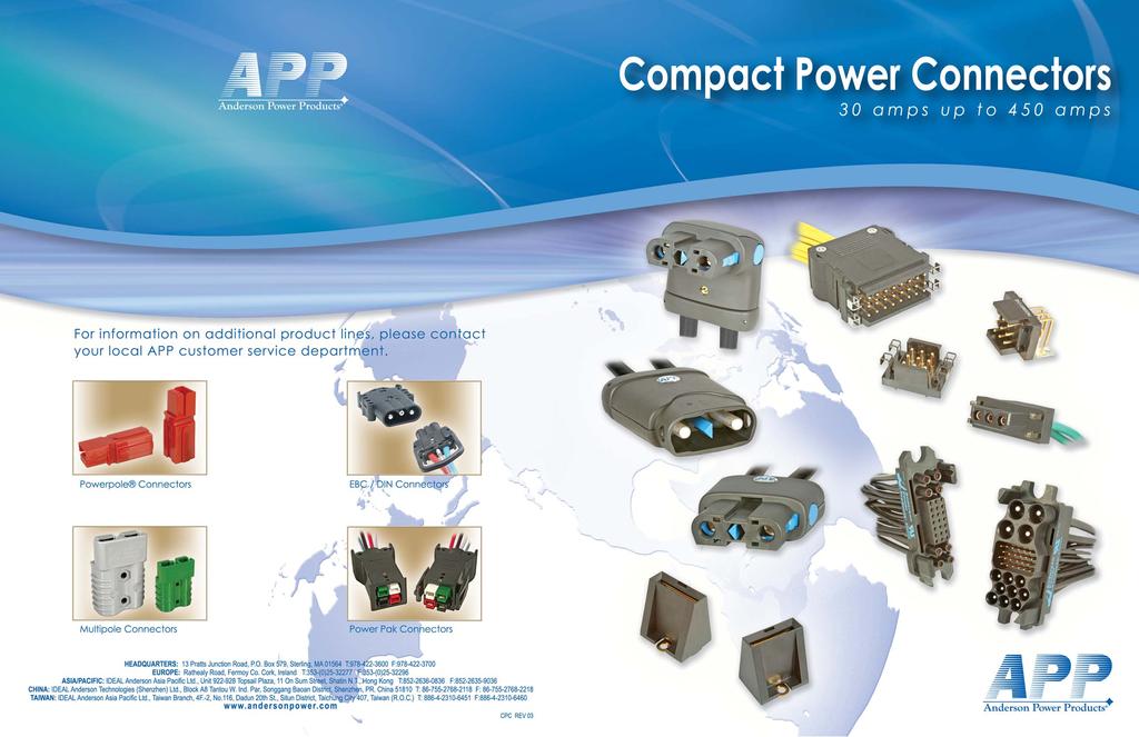
Performed with Emotion. Built by Intelligence. Batteriestecker Compact Power Connectors
|
|
|
- Georgiana Miller
- 5 years ago
- Views:
Transcription


1 Performed with Emotion Built by Intelligence Batteriestecker Compact Power Connectors
2

3 Anderson Power Products APP s philosophy is to provide products and services within the trading markets of our customers. We currently serve our world-wide customer base from customer support and manufacturing facilities in Sterling, MA, U.S.A., Fermoy, Ireland for European customers, as well as three Asia Pacific facilities: Shenzhen, China, Shatin Hong Kong and Taichung City 7, Taiwan (R.O.C.). Today, as a result of innovative design and development, APP has evolved into a valued supplier for a wide variety of markets including Back-up Power, Telecom/Datacom and the Material Handling Industries. APP has established a reputation for high quality products, on-time deliveries, and excellent customer service. As a result of modern manufacturing techniques and rigorous quality control measures, APP assures that customers receive the quality products they deserve. As a global company dedicated to best environmental practice, APP has taken steps to meet the RoHS directive for virtually all of their products. APP believes that general compliance with the RoHS directive is not enough and that the RoHS status for individual APP products must be readily accessible to customers twenty-four hours a day, seven days a week. The APP website search system allows customers to enter a part number and determine a product s compliance status to the RoHS directive. APP looks forward to the challenges posed by the new technologies of the future and will continue its century long tradition of design excellence and superior customer support to meet customers needs. may revise terms and conditions from time to time without notice. APP maintains this catalog as a service to its customers. The entire content (photographs and text) is copyrighted 6 and may not be distributed, modified, reused, or otherwise used, except as provided herein, without the express written permission of APP. You may use the content only for your personal, non-commercial use. APP will use reasonable efforts to include accurate and up-to-date content in the catalog. All product information contained in the catalog including illustrations, specifications, and dimensions, are believed to be reliable as of the date of publishing, but is subject to change without notice. APP makes no warranty or representation as to its accuracy. Content in the catalog may contain technical inaccuracies, typographical errors and may be changed or updated without notice. Current sales drawings and specifications are available upon request. Neither APP nor any party involved in creating, producing, or delivering this catalog shall be liable for any direct, incidental, consequential, indirect, or punitive damages arising out of your use of this catalog or any errors or omissions in its content. All product names, whether or not appearing in large print or with the trademark symbol, including, but not limited to A, A in circle, Anderson Power Products, PowerMod, Power Drawer, Power Clip and ACARA are trademarks of APP, its affiliates, related companies, licensers, and/or joint venture partners. The use or misuse of these trademarks, or any other content of this catalog, except as permitted herein, is expressly prohibited and may be in violation of intellectual property laws, which shall be aggressively enforced.
4 Index, an ISO 91: certified company, is a world leader in the design and manufacture of quick-disconnect power connectors. Our connectors are rated from 3 amps to 45 amps and up to 25 or 6 volts, AC/DC and comply with major worldwide specifications. With over one hundred years of power connection and device experience, we provide off-the-shelf and custom solutions for OEMs. Contents PowerMod HP A Series... 2 Single Pole Male... 4 Single Pole Female... 6 Single Pole Right Angle Female... 8 Bus Bar Mount... 1 Dual Pole Male Dual Pole Female Dual Pole Right Angle Female Dual Pole Panel Mount Male Dual Pole Panel Mount Blind Mate Female... PowerMod HP B Series Single Pole Male Single Pole Female Single Pole Right Angle Female Bus Bar Mount... 3 Dual Pole Male Dual Pole Female Dual Pole Right Angle Female Dual Pole Panel Mount Male Dual Pole Panel Mount Blind Mate Female... Power Drawer Series amp Series amp Series Cross Reference PowerMod Series One Row Female One Row Male Two Row Female... 6 Two Row Male Three Row Female Three Row Male Accessories Power Clip Series Power Clip... 8 Rocker Power Clip ACARA Series & 1 amp Two Pole Male Filter & Female Power Connector & 25 amp Two Pole Male Filter & Female Power Connector... 9 Wire Conversion Chart Interpretation of Charts Glossary of Terminology Index Copyright 6 The data herein are solely for your information and not offered, or to be construed, as a warranty or contractual responsibility
5 PowerMod HP Connector Family - Series A FEATURES Positive latching Integral latches with ergonomic release provide over 5 lbs retention Available in straight, right angle, panel mount, blind mate and bus bar styles The flexibility of the PowerMod HP system serves a broad range of electronics applications Touch safe female connectors Provide IP protection for safe, energized use outside the electronics cabinet Polarized dual pole connectors with optional hex key Dual pole housings prevent shorting from reverse mating and the optional hex key allows the user to create unique mating schemes Strain relief option Reduces risk of wire insulation creep and reduces transmission of wire loads to contacts improving service life Low connector mating forces Connectors are easily mated and un-mated Silver plated, high conductivity contacts Offers greater longevity for high power, elevated temperature applications Ease of assembly Intuitive design allows for simplicity of assembly UL Current Rating SP 2 Amps DP 21 Amps CSA (3 C Rise) 13 Amps Mating Force SP 7 lbs. (31.14N) DP 15 lbs. (66.72N) UL Voltage Rating 6 Volts Wire Size (AWG) #6 to #2 (mm²) 16 to 35 Insulation Withstanding Voltage 2 Volts Operating Temperature Range C minus -13 C Ambient Temperature Range C minus -85 C Latch Retention Force 5 lbs. (222N) min. Contact Retention Force 1 lbs. (445N) min. Mating a. No Load(Contact/Disconnect Cycles) 5 Cycles b. Under Load(Hot Plug 25 1V) 8A Housing & Cable Clamp PBT UL94 V- Latch PEI UL94 V- Contacts Copper alloy Hardware Steel zinc chromate File No. E26226 PRODUCT INFORMATION PowerMod HP connectors, developed by Anderson Power Products, are the innovative New Generation of High Power Interconnections for the Electronics Industry. The product family provides; cost effective reliability, superior safety and ergonomics, with broad design flexibility. The positive latch and optional strain relief of PowerMod HP connectors ensure superior reliability. The contacts are extremely durable and rated for circuit interruption (true hot-pluggable). Our touch-safe female housing design with integral latch release presents a new standard for high power connector safety and ergonomics. The housings are black UL94 V- material with latches in blue for clear identification. The PowerMod HP family offers excellent design flexibility with the availability of 1 different connector types. Single Pole Straight Male Dual Pole Straight Male Single Pole Right Angle Female Dual Pole Right Angle Female Single Pole Straight Female Dual Pole Straight Female Single Pole Bus Bar Mount Dual Pole Female Blind Mate Panel Mount Dual Pole Male Panel Mount Dual Pole Male Blind Mate Panel Mount All PowerMod HP connectors are available in American and metric wire sizes for further design freedom. APP offers pneumatic and hydraulic bench tools as well as hand tools for the products which are also compatible with many third-party crimp tooling. Applications: Back-Up Power, Power Supplies, Cellular Infrastructure, Telecommunications, Industrial Power


6 Connector Family - Series A Single Pole Right Angle Female Single Pole Male & Female Bus Bar Mount Dual Pole Right Angle Female Dual Pole Male & Female Dual Pole Panel Mount Male Dual Pole Blindmate Female Dual Pole Blindmate Male All Data Subject To Change Without Notice - 3 -
7 PowerMod HP Single Pole Male - Series A PowerMod HP connectors, developed by Anderson Power Products, are the innovative New Generation of High Power Interconnections for the Electronics Industry. The touch-safe, positive latching, PowerMod HP female connector design presents a new standard for high power connector safety. The ergonomic latch release is simple to operate and is colored blue for clear identification. Housings are a black UL94 V- flame retardant material. PowerMod HP contacts are durable and rated for circuit interruption (true hot-pluggable). Series A contacts are available in #6 to #2 American wire gauge and 16mm 2 to 35mm 2 metric wire sizes for global design freedom. Our optional strain relief ensures superior contact reliability under adverse operating conditions. APP PowerMod HP connectors embody the highest quality in the industry and meet all applicable industry standards. PowerMod HP Plan - Single Pole Male Components Series Series Gender Model Wire Size PMHP A M 1 P5 A * M - Male 1 - Single Pole Straight 2 - Single Pole Straight with Cable Clamp P5-6 AWG P4-16mm² P3-4 AWG P2-25mm² P1-2 AWG & 35mm² * Maximum wire size 2 AWG or 35mm² Features Positive latching Integral latches with ergonomic release provide over 5 lbs retention Strain relief option Reduces risk of wire insulation creep and reduces transmission of wire loads to contacts improving service life Low connector mating forces Connectors are easily mated and un-mated Silver plated, high conductivity contacts Offers greater longevity for high power, elevated temperature applications Ease of assembly Intuitive design allows for simplicity of assembly SPECIFICATIONS Electrical Mechanical Current Rating Mating Force 7 lbs. (31.14N) avg UL 2 Amps Latch Retention Force 5 lbs. (222N) min CSA (3 C Rise) 13 Amps Contact Retention Force 1 lbs. (445N) min UL / CSA Voltage Rating 6 Volts Mating Wire Size (AWG) #6 to #2 a. No Load(Contact/Disconnect Cycles) 5 Cycles (mm²) 16 to 35 b. Under Load(Hot Plug 25 1V) 8A Insulation Withstanding Voltage 2 Volts Materials Operating Temperature Range C minus -13 C Housing & Cable Clamp PBT UL94 V- Ambient Temperature Range C minus -85 C Latch PEI UL94 V- File No. E26226 Contacts Hardware PMHPAM1 PMHPAM2 PMHPAP5 PMHPAP4 PMHPAP3 PMHPAP2 PMHPAP1 PMHPAC1 Copper alloy silver plate Steel zinc chromate Housing Kit, Male, Single Pole, Straight Housing Kit with Cable Clamp, Male, Single Pole, Straight Pin, Series A, Crimp for 6 AWG wire Pin, Series A, Crimp for 16mm² wire Pin, Series A, Crimp for 4 AWG wire Pin, Series A, Crimp for 25mm² wire Pin, Series A, Crimp for 2 AWG & 35mm² wire Single Pole Cable Clamp Kit - 4 -
8 Tooling DIMENSIONS Front Without Front With Strain Relief Strain Relief Side Wire Size [ 33.2 ] 1.31 Pneumatic Production Tool Die P/N Locator P/N [ 31 ] 1.22 [ 34.8 ] 1.37 of Crimps #2 AWG 35mm² 1387G2 133G13 134G mm² 1387G2 133G13 134G19 2 #4 AWG 1387G2 133G14 134G mm² 1387G2 133G14 134G19 2 #6 AWG 1387G2 133G14 134G19 2 Hand Tool Wire Size Hydraulic Battery Die P/N of Crimps #2 AWG 35mm² 1387G G7 2 25mm² 1387G G11 2 #4 AWG 1387G G8 2 16mm² 1387G G1 2 #6 AWG 1387G G9 2 [ 37.1 ] 1.46 Temperature ( C) Ambient Temperature ( C) Single Pole Male - Series A TEMPERATURE CHART PowerMod HP Single Pole Series A Temperature Rise Current (A) 2 AWG 4 AWG 6 AWG * Double crimp is required to achieve stated electrical specifications PowerMod HP Single Pole De-rating Curve Series A Per IEC Current (A) 2 AWG 4 AWG 6 AWG * Double crimp is required to achieve stated electrical specifications MATING CONNECTORS Single Pole Right Single Pole Female Angle Female [ 65.1 ] 2.56 [ 8.2 ] 3.16 All Data Subject To Change Without Notice - 5 -
9 PowerMod HP Single Pole Female - Series A PowerMod HP connectors, developed by Anderson Power Products, are the innovative New Generation of High Power Interconnections for the Electronics Industry. The touch-safe, positive latching, PowerMod HP female connector design presents a new standard for high power connector safety. The ergonomic latch release is simple to operate and is colored blue for clear identification. Housings are a black UL94 V- flame retardant material. PowerMod HP contacts are durable and rated for circuit interruption (true hot-pluggable). Series A contacts are available in #6 to #2 American wire gauge and 16mm 2 to 35mm 2 metric wire sizes for global design freedom. Our optional strain relief ensures superior contact reliability under adverse operating conditions. APP PowerMod HP connectors embody the highest quality in the industry and meet all applicable industry standards. Features Positive Latching Integral latches with ergonomic release provide over 5 lbs retention Touch safe female connectors Provides IP protection for safe, energized use outside the electronics cabinet High performance, hot pluggable female contacts Our patented design provides greater longevity for high power, elevated temperature applications Strain relief option Reduces risk of wire insulation creep and reduces transmission of wire loads to contacts improving service life Low connector mating forces Connectors are easily mated and un-mated SPECIFICATIONS Electrical Mechanical Current Rating Mating Force 7 lbs. (31.14N) avg UL 2 Amps Latch Retention Force 5 lbs. (222N) min CSA (3 C Rise) 13 Amps Contact Retention Force 1 lbs. (445N) min UL / CSA Voltage Rating 6 Volts Mating Wire Size (AWG) #6 to #2 a. No Load(Contact/Disconnect Cycles) 5 Cycles (mm²) 16 to 35 b. Under Load(Hot Plug 25 1V) 8A Insulation Withstanding Voltage 2 Volts Materials Operating Temperature Range C minus -13 C Housing & Cable Clamp PBT UL94 V- Ambient Temperature Range C minus -85 C Latch PEI UL94 V- File No. E26226 PowerMod HP Plan - Single Pole Female Series Series Gender Model Wire Size PMHP A F 1 S5 A * F - Female 1 - Single Pole Straight 2 - Single Pole Straight with Cable Clamp S5-6 AWG S4-16mm² S3-4 AWG S2-25mm² S1-2 AWG & 35mm² * Maximum wire size 2 AWG or 35mm² Components PMHPAF1 PMHPAF2 PMHPAS5 PMHPAS4 PMHPAS3 PMHPAS2 PMHPAS1 PMHPAC1 Housing Kit, Female, Single Pole, Straight Housing Kit with Cable Clamp,Female, Single Pole, Straight Socket, Series A, Crimp for 6 AWG wire Socket, Series A, Crimp for 16mm² wire Socket, Series A, Crimp for 4 AWG wire Socket, Series A, Crimp for 25mm² wire Socket, Series A, Crimp for 2 AWG & 35mm² wire Single Pole Cable Clamp Kit Contacts Hardware Copper alloy silver plate Steel zinc chromate
10 Tooling DIMENSIONS Front Without Front With Strain Relief Strain Relief Side [ 33.2 ] 1.31 Wire Size Pneumatic Production Tool Die P/N Locator P/N [ 3.6 ] 1.21 [ 34.7 ] 1.36 of Crimps #2 AWG 35mm² 1387G2 133G13 134G mm² 1387G2 133G13 134G19 2 #4 AWG 1387G2 133G14 134G mm² 1387G2 133G14 134G19 2 #6 AWG 1387G2 133G14 134G19 2 Hand Tool Wire Size Hydraulic Battery Die P/N of Crimps #2 AWG 35mm² 1387G G7 2 25mm² 1387G G11 2 #4 AWG 1387G G8 2 16mm² 1387G G1 2 #6 AWG 1387G G9 2 [ 37.1 ] 1.46 Temperature ( C) Ambient Temperature ( C) Single Pole Female - Series A TEMPERATURE CHART PowerMod HP Single Pole Series A Temperature Rise Current (A) 2 AWG 4 AWG 6 AWG * Double crimp is required to achieve stated electrical specifications PowerMod HP Single Pole De-rating Curve Series A Per IEC * Double crimp is required to achieve stated electrical specifications MATING CONNECTORS Single Pole Bus Bar Male Current (A) 2 AWG 4 AWG 6 AWG Single Pole Male [ 65.2 ] 2.57 [ 82.1 ] 3.23 All Data Subject To Change Without Notice - 7 -

11 PowerMod HP Single Pole Right Angle Female - Series A PowerMod HP connectors, developed by Anderson Power Products, are the innovative New Generation of High Power Interconnections for the Electronics Industry. The touch-safe, positive latching, PowerMod HP female connector design presents a new standard for high power connector safety. The ergonomic latch release is simple to operate and is colored blue for clear identification. Housings are a black UL94 V- flame retardant material. PowerMod HP contacts are durable and rated for circuit interruption (true hot-pluggable). Series A contacts are available in #6 to #2 American wire gauge and 16mm 2 to 35mm 2 metric wire sizes for global design freedom. Our *strain relief ensures superior contact reliability under adverse operating conditions. APP PowerMod HP connectors embody the highest quality in the industry and meet all applicable industry standards. * Strain relief not optional on right angle Features Right angle connector Offers short mated length for tight wiring applications Positive latching Integral Latches with ergonomic release provide over 5 lbs retention Touch safe female connectors Provides IP protection for safe, energized use outside the electronics cabinet High performance, hot pluggable female contacts Our patented design provides greater longevity for high power, elevated temperature applications Low connector mating forces Connectors are easily mated and un-mated SPECIFICATIONS Electrical Mechanical Current Rating Mating Force 7 lbs. (31.14N) avg UL 2 Amps Latch Retention Force 5 lbs. (222N) min CSA (3 C Rise) 13 Amps Contact Retention Force 1 lbs. (445N) min UL / CSA Voltage Rating 6 Volts Mating Wire Size (AWG) #6 to #2 a. No Load(Contact/Disconnect Cycles) 5 Cycles (mm²) 16 to 35 b. Under Load(Hot Plug 25 1V) 8A Insulation Withstanding Voltage 2 Volts Materials Operating Temperature Range C minus -13 C Housing & Cable Clamp PBT UL94 V- Ambient Temperature Range C minus -85 C Latch PEI UL94 V- File No. E26226 PowerMod HP Plan - Single Pole Right Components Angle Female Series Series Gender Model Wire Size PMHP A F 3 S1 A * F - Female 3 - Single Pole R/A with cable clamp S1-6 AWG S9-16mm² S8-4 AWG S7-25mm² S6-2 AWG & 35mm² * Maximum wire size 2 AWG or 35mm² PMHPAF3 PMHPAS1 PMHPAS9 PMHPAS8 PMHPAS7 PMHPAS6 Housing Kit with Cable Clamp,Female, Single Pole, R/A Socket, Series A, Crimp for 6 AWG wire Socket, Series A, Crimp for 16mm² wire Socket, Series A, Crimp for 4 AWG wire Socket, Series A, Crimp for 25mm² wire Socket, Series A, Crimp for 2 AWG & 35mm² wire Contacts Hardware Copper alloy silver plate Steel zinc chromate
12 Single Pole Right Angle Female - Series A Tooling Side Wire Size Pneumatic Production Tool Die P/N Locator P/N DIMENSIONS of Crimps #2 AWG 35mm² 1387G2 133G13 134G mm² 1387G2 133G13 134G19 2 #4 AWG 1387G2 133G14 134G mm² 1387G2 133G14 134G19 2 #6 AWG 1387G2 133G14 134G19 2 Hand Tool Wire Size Hydraulic Battery Die P/N of Crimps #2 AWG 35mm² 1387G G7 2 25mm² 1387G G11 2 #4 AWG 1387G G8 2 16mm² 1387G G1 2 #6 AWG 1387G G9 2 [ 26.4 ] 1.4 [ 7.1 ] 2.76 Temperature ( C) Ambient Temperature ( C) TEMPERATURE CHART PowerMod HP Single Pole Series A Temperature Rise Current (A) 2 AWG 4 AWG 6 AWG * Double crimp is required to achieve stated electrical specifications PowerMod HP Single Pole De-rating Curve Series A Per IEC Current (A) 2 AWG 4 AWG 6 AWG * Double crimp is required to achieve stated electrical specifications Top Front MATING CONNECTORS Single Pole Male Single Pole Bus Bar Male [ 68.3 ] 2.69 [ 37.1 ] 1.46 All Data Subject To Change Without Notice - 9 -
13 PowerMod HP connectors, developed by Anderson Power Products, are the innovative New Generation of High Power Interconnections for the Electronics Industry. APP PowerMod HP connectors embody the highest quality in the industry and meet all applicable industry standards. Features PowerMod HP Single Pole Bus Bar - Series A Low connector mating forces Connectors are easily mated and un-mated Silver plated, high conductivity contacts Offers greater longevity for high power, elevated temperature applications Ease of assembly Intuitive design allows for simplicity of assembly SPECIFICATIONS Electrical Mechanical Current Rating Mating Force 7 lbs. (31.14N) avg UL 2 Amps Latch Retention Force 5 lbs. (222N) min CSA (3 C Rise) 13 Amps Contact Retention Force 1 lbs. (445N) min UL / CSA Voltage Rating 6 Volts Mating Bus Bar.12 [3.] min a. No Load(Contact/Disconnect Cycles) 5 Cycles.25 [6.4] max b. Under Load(Hot Plug 25 1V) 8A Insulation Withstanding Voltage 2 Volts Materials Operating Temperature Range C minus -13 C Housing PBT UL94 V- Ambient Temperature Range C minus -85 C Contacts Copper alloy silver plate Hardware Steel zinc chromate File No. E26226 PowerMod HP Plan - Single Pole Bus Bar Components Series Series Gender Model Wire Size PMHP A M 4 P6 A * M - Male 4 - Bus Bar Mount P6 - Pin Bus Bar PMHPAP6 Pin Series A, Bus Bar - 1 -
14 Single Pole Bus Bar - Series A Front Wire Size Tooling For Mating Connectors Pneumatic Production Tool Die P/N Locator P/N DIMENSIONS of Crimps #2 AWG 35mm² 1387G2 133G13 134G mm² 1387G2 133G13 134G19 2 #4 AWG 1387G2 133G14 134G mm² 1387G2 133G14 134G19 2 #6 AWG 1387G2 133G14 134G19 2 Hand Tool Wire Size Hydraulic Battery Die P/N of Crimps #2 AWG 35mm² 1387G G7 2 25mm² 1387G G11 2 #4 AWG 1387G G8 2 16mm² 1387G G1 2 #6 AWG 1387G G9 2 [ 23.4 ].92 [ 23.4 ].92 Temperature ( C) Ambient Temperature ( C) TEMPERATURE CHART PowerMod HP Single Pole Series A Temperature Rise Current (A) 2 AWG 4 AWG 6 AWG * Double crimp is required to achieve stated electrical specifications PowerMod HP Single Pole De-rating Curve Series A Per IEC Side [ 3.5 ] 1. BUSBAR Current (A) 2 AWG 4 AWG 6 AWG * Double crimp is required to achieve stated electrical specifications [ 13.1 ].52 MATING CONNECTORS Single Pole Right Single Pole Female Angle Female Back 45 [ 1.16 ]. [ 4.83 ] [ 7.49 ] Ø.19 Ø.295 HOUSING OUTLINE All Data Subject To Change Without Notice
15 PowerMod HP connectors, developed by Anderson Power Products, are the innovative New Generation of High Power Interconnections for the Electronics Industry. The touch-safe, positive latching, PowerMod HP female connector design presents a new standard for high power connector safety. The ergonomic latch release is simple to operate and is colored blue for clear identification. Housings are a black UL94 V- flame retardant material. PowerMod HP contacts are durable and rated for circuit interruption (true hot-pluggable). Series A contacts are available in #6 to #2 American wire gauge and 16mm 2 to 35mm 2 metric wire sizes for global design freedom. Our optional strain relief ensures superior contact reliability under adverse operating conditions. APP PowerMod HP connectors embody the highest quality in the industry and meet all applicable industry standards. Features Positive latching Integral latches with ergonomic release provide over 5 lbs retention Strain relief option Reduces risk of wire insulation creep and reduces transmission of wire loads to contacts improving service life Low connector mating forces Connectors are easily mated and un-mated Silver plated, high conductivity contacts Offers greater longevity for high power, elevated temperature applications Ease of assembly Intuitive design allows for simplicity of assembly SPECIFICATIONS PowerMod HP Dual Pole Male - Series A Electrical Mechanical Current Rating Mating Force 15 lbs. (66.72N) avg UL 21 Amps Latch Retention Force 5 lbs. (222N) min CSA (3 C Rise) 13 Amps Contact Retention Force 1 lbs. (445N) min UL / CSA Voltage Rating 6 Volts Mating Wire Size (AWG) #6 to #2 a. No Load(Contact/Disconnect Cycles) 5 Cycles (mm²) 16 to 35 b. Under Load(Hot Plug 25 1V) 8A Insulation Withstanding Voltage 2 Volts Materials Operating Temperature Range C minus -13 C Housing & Cable Clamp PBT UL94 V- Ambient Temperature Range C minus -85 C Latch PEI UL94 V- File No. E26226 PowerMod HP Plan - Dual Pole Male Components Series Series Gender Model Wire Size PMHP A M 11 P5 A * M - Male 11 - Dual Pole Straight 12 - Dual Pole Straight with Cable Clamp P5-6 AWG P4-16mm² P3-4 AWG P2-25mm² P1-2 AWG & 35mm² * Maximum wire size 2 AWG or 35mm² PMHPAM11 PMHPAM12 PMHPAP5 PMHPAP4 PMHPAP3 PMHPAP2 PMHPAP1 PMHPAC2 Housing Kit, Male, Dual Pole, Straight Housing Kit with Cable Clamp, Male, Dual Pole, Straight Pin, Series A, Crimp for 6 AWG wire Pin, Series A, Crimp for 16mm² wire Pin, Series A, Crimp for 4 AWG wire Pin, Series A, Crimp for 25mm² wire Pin, Series A, Crimp for 2 AWG & 35mm² wire Dual Pole Cable Clamp Kit Contacts Hardware Copper alloy silver plate Steel zinc chromate
16 Tooling Front Without Strain Relief Side Wire Size Pneumatic Production Tool Die P/N Locator P/N DIMENSIONS of Crimps #2 AWG 35mm² 1387G2 133G13 134G mm² 1387G2 133G13 134G19 2 #4 AWG 1387G2 133G14 134G mm² 1387G2 133G14 134G19 2 #6 AWG 1387G2 133G14 134G19 2 Hand Tool Wire Size Hydraulic Battery Die P/N of Crimps #2 AWG 35mm² 1387G G7 2 25mm² 1387G G11 2 #4 AWG 1387G G8 2 16mm² 1387G G1 2 #6 AWG 1387G G9 2 [ 29.2 ] [ 63.7 ] 1.15 [ 29.9 ] [ 65.7 ] 2.59 [ 82.6 ] 3.25 Temperature ( C) Ambient Temperature ( C) Dual Pole Male - Series A TEMPERATURE CHART PowerMod HP Dual Pole Series A Temperature Rise Current (A) 2 AWG 4 AWG 6 AWG * Double crimp is required to achieve stated electrical specifications PowerMod HP Dual Pole De-rating Curve Series A Per IEC Current (A) 2 AWG 4 AWG 6 AWG * Double crimp is required to achieve stated electrical specifications MATING CONNECTORS Dual Pole Straight Dual Pole Right Angle Female Female Front With Strain Relief [ 67.2 ] 2.65 All Data Subject To Change Without Notice

17 PowerMod HP Dual Pole Female - Series A PowerMod HP connectors, developed by Anderson Power Products, are the innovative New Generation of High Power Interconnections for the Electronics Industry. The touch-safe, positive latching, PowerMod HP female connector design presents a new standard for high power connector safety. The ergonomic latch release is simple to operate and is colored blue for clear identification. Housings are a black UL94 V- flame retardant material. PowerMod HP contacts are durable and rated for circuit interruption (true hot-pluggable). Series A contacts are available in #6 to #2 American wire gauge and 16mm 2 to 35mm 2 metric wire sizes for global design freedom. Our optional strain relief ensures superior contact reliability under adverse operating conditions. APP PowerMod HP connectors embody the highest quality in the industry and meet all applicable industry standards. Features Positive latching Integral latches with ergonomic release provide over 5 lbs retention Touch safe female connectors Provides IP protection for safe, energized use outside the electronics cabinet High performance, hot pluggable female contacts Our patented design provides greater longevity for high power, elevated temperature applications Strain relief option Reduces risk of wire insulation creep and reduces transmission of wire loads to contacts improving service life Low connector mating forces Connectors are easily mated and un-mated Electrical Mechanical Current Rating Mating Force 15 lbs. (66.72N) avg UL 21 Amps Latch Retention Force 5 lbs. (222N) min CSA (3 C Rise) 13 Amps Contact Retention Force 1 lbs. (445N) min UL / CSA Voltage Rating 6 Volts Mating Wire Size (AWG) #6 to #2 a. No Load(Contact/Disconnect Cycles) 5 Cycles (mm²) 16 to 35 b. Under Load(Hot Plug 25 1V) 8A Insulation Withstanding Voltage 2 Volts Materials Operating Temperature Range C minus -13 C Housing & Cable Clamp PBT UL94 V- Ambient Temperature Range C minus -85 C Latch PEI UL94 V- File No. E26226 PowerMod HP Plan - Dual Pole Female Components Series Series Gender Model Wire Size PMHP A F 11 S5 A * F - Female 11 - Dual Pole Straight 12 - Dual Pole Straight with Cable Clamp S5-6 AWG S4-16mm² S3-4 AWG S2-25mm² S1-2 AWG & 35mm * Maximum wire size 2 AWG or 35mm² SPECIFICATIONS Contacts Hardware PMHPAF11 PMHPAF12 PMHPAS5 PMHPAS4 PMHPAS3 PMHPAS2 PMHPAS1 PMHPAC2 Copper alloy silver plate Steel zinc chromate Housing Kit, Female, Dual Pole, Straight Housing Kit with Cable Clamp, Female, Dual Pole, Straight Socket, Series A, Crimp for 6 AWG wire Socket, Series A, Crimp for 16mm² wire Socket, Series A, Crimp for 4 AWG wire Socket, Series A, Crimp for 25mm² wire Socket, Series A, Crimp for 2 AWG & 35mm² wire Dual Pole Cable Clamp Kit
18 Tooling Wire Size Accessories PMHPAFDC Front Without Strain Relief Dust Cover [ 63.7 ] 2.51 Pneumatic Production Tool Die P/N Locator P/N DIMENSIONS Front With Strain Relief [ 67.3 ] 2.65 of Crimps #2 AWG 35mm² 1387G2 133G13 134G mm² 1387G2 133G13 134G19 2 #4 AWG 1387G2 133G14 134G mm² 1387G2 133G14 134G19 2 #6 AWG 1387G2 133G14 134G19 2 Hand Tool Wire Size Hydraulic Battery Die P/N of Crimps #2 AWG 35mm² 1387G G7 2 25mm² 1387G G11 2 #4 AWG 1387G G8 2 16mm² 1387G G1 2 #6 AWG 1387G G9 2 [ 29.8 ] 1.17 Temperature ( C) Ambient Temperature ( C) Dual Pole Straight Male Dual Pole Female - Series A TEMPERATURE CHART PowerMod HP Dual Pole Series A Temperature Rise Current (A) 2 AWG 4 AWG 6 AWG * Double crimp is required to achieve stated electrical specifications PowerMod HP Dual Pole De-rating Curve Series A Per IEC Current (A) 2 AWG 4 AWG 6 AWG * Double crimp is required to achieve stated electrical specifications MATING CONNECTORS Dual Pole Panel Mount Male Side [ 66.8 ] 2.63 [ 82.2 ] 3.23 All Data Subject To Change Without Notice
19 PowerMod HP Dual Pole Right Angle Female - Series A PowerMod HP connectors, developed by Anderson Power Products, are the innovative New Generation of High Power Interconnections for the Electronics Industry. The touch-safe, positive latching, PowerMod HP female connector design presents a new standard for high power connector safety. The ergonomic latch release is simple to operate and is colored blue for clear identification. Housings are a black UL94 V- flame retardant material. PowerMod HP contacts are durable and rated for circuit interruption (true hotpluggable). Series A contacts are available in #6 to #2 American wire gauge and 16mm 2 to 35mm 2 metric wire sizes for global design freedom. Our *strain relief ensures superior contact reliability under adverse operating conditions. APP PowerMod HP connectors embody the highest quality in the industry and meet all applicable industry standards. Features Right angle connector Offers short mated length for tight wiring applications Positive latching Integral Latches with ergonomic release provide over 5 lbs retention Touch safe female connectors Provides IP protection for safe, energized use outside the electronics cabinet High performance, hot pluggable female contacts Our patented design provides greater longevity for high power, elevated temperature applications Low connector mating forces Connectors are easily mated and un-mated * Strain relief not optional on right angle Electrical Mechanical Current Rating Mating Force 15 lbs. (66.72N) avg UL 21 Amps Latch Retention Force 5 lbs. (222N) min CSA (3 C Rise) 13 Amps Contact Retention Force 1 lbs. (445N) min UL / CSA Voltage Rating 6 Volts Mating Wire Size (AWG) #6 to #2 a. No Load(Contact/Disconnect Cycles) 5 Cycles (mm²) 16 to 35 b. Under Load(Hot Plug 25 1V) 8A Insulation Withstanding Voltage 2 Volts Materials Operating Temperature Range C minus -13 C Housing & Cable Clamp PBT UL94 V- Ambient Temperature Range C minus -85 C Latch PEI UL94 V- File No. E26226 PowerMod HP Plan - Dual Pole Right Angle Female Series Series Gender Model Wire Size PMHP A F 13 S1 A * F - Female 13 - Dual Pole R/A with Cable Clamp S1-6 AWG S9-16mm² S8-4 AWG S7-25mm² S6-2 AWG & 35mm² * Maximum wire size 2 AWG or 35mm² SPECIFICATIONS Components PMHPAF13 PMHPAS1 PMHPAS9 PMHPAS8 PMHPAS7 PMHPAS6 Housing Kit With Cable Clamp, Female, Dual Pole, R/A Socket, Series A, Crimp for 6 AWG wire Socket, Series A, Crimp for 16mm² wire Socket, Series A, Crimp for 4 AWG wire Socket, Series A, Crimp for 25mm² wire Socket, Series A, Crimp for 2 AWG & 35mm² wire Contacts Hardware Copper alloy silver plate Steel zinc chromate
20 Dual Pole Right Angle Female - Series A Tooling Wire Size Accessories PMHPAFDC Die P/N Locator P/N Dust Cover DIMENSIONS Side With Strain Relief [ 29.2 ] 1.15 of Crimps #2 AWG 35mm² 1387G2 133G13 134G mm² 1387G2 133G13 134G19 2 #4 AWG 1387G2 133G14 134G mm² 1387G2 133G14 134G19 2 #6 AWG 1387G2 133G14 134G19 2 Wire Size Hydraulic Battery Die P/N of Crimps #2 AWG 35mm² 1387G G7 2 25mm² 1387G G11 2 #4 AWG 1387G G8 2 16mm² 1387G G1 2 #6 AWG 1387G G9 2 Front With Strain Relief Pneumatic Production Tool Hand Tool [ 25.5 ] 1.1 Temperature ( C) Ambient Temperature ( C) TEMPERATURE CHART PowerMod HP Dual Pole Series A Temperature Rise Current (A) 2 AWG 4 AWG 6 AWG * Double crimp is required to achieve stated electrical specifications PowerMod HP Dual Pole De-rating Curve Series A Per IEC Current (A) 2 AWG 4 AWG 6 AWG * Double crimp is required to achieve stated electrical specifications Top [ 67.2 ] 26.5 [ 63.8 ] 2.51 [ 67 ] 2.64 MATING CONNECTORS Dual Pole Dual Pole Panel Straight Male Mount Male All Data Subject To Change Without Notice
21 PowerMod HP connectors, developed by Anderson Power Products, are the innovative New Generation of High Power Interconnections for the Electronics Industry. The touch-safe PowerMod HP female panel connector is designed for high power connector safety. Male panel connectors are designed for blind mating with female panel connectors or positive latching with female cable connectors. Housings are a black UL94 V- flame retardant material. PowerMod HP contacts are durable and rated for circuit interruption (true hotpluggable). Series A contacts are available in #6 to #2 American wire gauge and 16mm 2 to 35mm 2 metric wire sizes for global design freedom. Our optional blind mating hardware accommodates up to +/-.125" (3mm) of misalignment and is available for both male and female panel connectors. PowerMod HP Dual Pole Panel Mount Male - Series A Features Positive latching Integral Latches with ergonomic release provide over 5 lbs retention Low connector mating forces Connectors are easily mated and un-mated Blind mate panel mount option Provides over +/-.125" (3mm) of float mount capability Ease of assembly Intuitive design allows for simplicity of assembly Panel Mount APP PowerMod HP connectors embody the highest quality in the industry and meet all applicable industry standards. SPECIFICATIONS Electrical Mechanical Panel Mount Blind Mate Current Rating Mating Force 15 lbs. (66.72N) avg UL 21 Amps Latch Retention Force 5 lbs. (222N) min CSA (3 C Rise) 13 Amps Contact Retention Force 1 lbs. (445N) min UL / CSA Voltage Rating 6 Volts Mating Wire Size (AWG) #6 to #2 a. No Load(Contact/Disconnect Cycles) 5 Cycles (mm²) 16 to 35 b. Under Load(Hot Plug 25 1V) 8A Insulation Withstanding Voltage 2 Volts Materials Operating Temperature Range C minus -13 C Housing & Cable Clamp PBT UL94 V- Ambient Temperature Range C minus -85 C Latch PEI UL94 V- File No. E26226 * Maximum wire size 2 AWG or 35mm² Contacts Hardware PowerMod HP Plan - Dual Pole Components Panel Mount Male Series Series Gender Model Wire Size PMHP A M 14 P5 A * M - Male 14 - Dual Pole Male Panel Mount 15 - Dual Pole Male Blindmate Panel Mount P5-6 AWG P4-16mm² P3-4 AWG P2-25mm² P1-2 AWG & 35mm² PMHPAM14 PMHPAM15 PMHPAP5 PMHPAP4 PMHPAP3 PMHPAP2 PMHPAP1 PMHPAFMH Copper alloy silver plate Steel zinc chromate Housing Kit, Male, Dual Pole, Panel Mount With Key Housing Kit, Male, Dual Pole, Panel Mount No Key With Blindmate Post Pin, Series A, Crimp for 6 AWG wire Pin, Series A, Crimp for 16mm² wire Pin, Series A, Crimp for 4 AWG wire Pin, Series A, Crimp for 25mm² wire Pin, Series A, Crimp for 2 AWG & 35mm² wire Float Mount Kit
22 Tooling Accessories PMHPAMDC Front Wire Size [ 91.9 ] 3.62 Dust Cover Pneumatic Production Tool Die P/N Locator P/N DIMENSIONS Top [ 39.8 ] 1.57 [ 9.8 ].39 of Crimps #2 AWG 35mm² 1387G2 133G13 134G mm² 1387G2 133G13 134G19 2 #4 AWG 1387G2 133G14 134G mm² 1387G2 133G14 134G19 2 #6 AWG 1387G2 133G14 134G19 2 Hand Tool Wire Size Hydraulic Battery Die P/N of Crimps #2 AWG 35mm² 1387G G7 2 25mm² 1387G G11 2 #4 AWG 1387G G8 2 16mm² 1387G G1 2 #6 AWG 1387G G9 2 OPTIONAL GUIDE POST FOR BLIND MATING [ 58.1 ] 2.29 [ 52.8 ] 2.8 [ 64.1 ] 2.53 Dual Pole Panel Mount Male - Series A Temperature ( C) Ambient Temperature ( C) MATING CONNECTORS Dual Pole Panel Mount Female - (mates with panel mount blind mate only) TEMPERATURE CHART PowerMod HP Dual Pole Series A Temperature Rise Current (A) 2 AWG 4 AWG 6 AWG * Double crimp is required to achieve stated electrical specifications PowerMod HP Dual Pole De-rating Curve Series A Per IEC Current (A) 2 AWG 4 AWG 6 AWG * Double crimp is required to achieve stated electrical specifications Cut Out [ ].625 [ ] 1.25 All Data Subject To Change Without Notice [ 61.9 ] [ ] [ ] (4) (FIXED MOUNT) (FLOAT MOUNT) [ 12.7 ].5 (2) [ 25. ] 1. (2) [3].12 MAX Dual Pole Straight Dual Pole Right Angle Female Female
23 PowerMod HP connectors, developed by Anderson Power Products, are the innovative New Generation of High Power Interconnections for the Electronics Industry. The touch-safe PowerMod HP female panel connector is designed for high power connector safety. Male panel connectors are designed for blind mating with female panel connectors or positive latching with female cable connectors. Housings are a black UL94 V- flame retardant material. PowerMod HP contacts are durable and rated for circuit interruption (true hotpluggable). Series A contacts are available in #6 to #2 American wire gauge and 16mm 2 to 35mm 2 metric wire sizes for global design freedom. Our optional blind mating hardware accommodates up to +/-.125" (3mm) of misalignment and is available for both male and female panel connectors. APP PowerMod HP connectors embody the highest quality in the industry and meet all applicable industry standards. SPECIFICATIONS Electrical Mechanical Current Rating Mating Force 15 lbs. (66.72N) avg UL 21 Amps Latch Retention Force 5 lbs. (222N) min CSA (3 C Rise) 13 Amps Contact Retention Force 1 lbs. (445N) min UL / CSA Voltage Rating 6 Volts Mating Wire Size (AWG) #6 to #2 a. No Load(Contact/Disconnect Cycles) 5 Cycles (mm²) 16 to 35 b. Under Load(Hot Plug 25 1V) 8A Insulation Withstanding Voltage 2 Volts Materials Operating Temperature Range C minus -13 C Housing & Cable Clamp PBT UL94 V- Ambient Temperature Range C minus -85 C Latch PEI UL94 V- File No. E26226 Features PowerMod HP Plan - Dual Pole Components Panel Mount Blind Mate Female Series Series Gender Model Wire Size PMHP A F 14 S1 A * F - Female 14 - Dual Pole Female Panel Mount S5-6 AWG S4-16mm² S3-4 AWG S2-25mm² S1-2 AWG & 35mm² Blind mate panel mount option Provides over +/-.125" (3mm) of float mount capability Touch safe female connectors Provides IP protection for safe, energized use outside the electronics cabinet High performance, hot pluggable female contacts Our patented design provides greater longevity for high power, elevated temperature applications Low connector mating forces Connectors are easily mated and un-mated Ease of assembly Intuitive design allows for simplicity of assembly PMHPAF14 PMHPAS5 PMHPAS4 PMHPAS3 PMHPAS2 PMHPAS1 PMHPAFMH Housing Kit, Female, Dual Pole, Panel Mount Socket, Series A, Crimp for 6 AWG wire Socket, Series A, Crimp for 16mm² wire Socket, Series A, Crimp for 4 AWG wire Socket, Series A, Crimp for 25mm² wire Socket, Series A, Crimp for 2 AWG & 35mm² wire Float Mount Kit * Maximum wire size 2 AWG or 35mm² - - Contacts Hardware PowerMod HP Dual Pole Panel Mount Blind Mate Female - Series A Copper alloy silver plate Steel zinc chromate
24 Dual Pole Panel Mount Blind Mate Female - Series A Tooling Accessories PMHPAFDC Front Wire Size [ 29.2 ] 1.15 [91.9] 3.62 Dust Cover Pneumatic Production Tool Die P/N Locator P/N DIMENSIONS Top [.2 ] 1.58 [ 23.6 ].93 [ 51.1 ] 2.1 of Crimps #2 AWG 35mm² 1387G2 133G13 134G mm² 1387G2 133G13 134G19 2 #4 AWG 1387G2 133G14 134G mm² 1387G2 133G14 134G19 2 #6 AWG 1387G2 133G14 134G19 2 Hand Tool Wire Size Hydraulic Battery Die P/N of Crimps #2 AWG 35mm² 1387G G7 2 25mm² 1387G G11 2 #4 AWG 1387G G8 2 16mm² 1387G G1 2 #6 AWG 1387G G9 2 [ 29.6 ] 1.17 [ 36.1 ] 1.42 Temperature ( C) Ambient Temperature ( C) TEMPERATURE CHART PowerMod HP Dual Pole Series A Temperature Rise Current (A) 2 AWG 4 AWG 6 AWG * Double crimp is required to achieve stated electrical specifications PowerMod HP Dual Pole De-rating Curve Series A Per IEC Current (A) 2 AWG 4 AWG 6 AWG * Double crimp is required to achieve stated electrical specifications MATING CONNECTORS Dual Pole Panel Mount Blind Mate Male Cut Out [ ].625 [ ] 1.25 All Data Subject To Change Without Notice [ 61.9 ] [ ] [ ] (4) [ 12.7 ] (FIXED MOUNT) (FLOAT MOUNT).5 (2) [ 25. ] 1. (2) [3].12 MAX

25 PowerMod HP Connector Family - Series B FEATURES Positive latching Integral latches with ergonomic release provide over 5 lbs retention Available in straight, right angle, panel mount, blind mate and bus bar styles The flexibility of the PowerMod HP system serves a broad range of electronics applications Touch safe female connectors Provide IP protection for safe, energized use outside the electronics cabinet Polarized dual pole connectors with optional hex key Dual pole housings prevent shorting from reverse mating and the optional hex key allows the user to create unique mating schemes Strain relief option Reduces risk of wire insulation creep and reduces transmission of wire loads to contacts improving service life Low connector mating forces Connectors are easily mated and un-mated Silver plated, high conductivity contacts Offers greater longevity for high power, elevated temperature applications Ease of assembly Intuitive design allows for simplicity of assembly UL Current Rating SP 45 Amps DP Amps CSA (3 C Rise) 25 Amps Mating Force SP 16.5 lbs. (74N) DP 33 lbs. (147N) UL Voltage Rating 6 Volts Wire Size (AWG) 1/ to 4/ (mm²) 5 to 95 Insulation Withstanding Voltage 2 Volts Operating Temperature Range C minus -13 C Ambient Temperature Range C minus -85 C Latch Retention Force 5 lbs. (222N) min. Contact Retention Force 15 lbs. (667N) min. Mating a. No Load(Contact/Disconnect Cycles) 5 Cycles b. Under Load(Hot Plug 25 1V) 15A Housing & Cable Clamp PBT UL94 V- Latch PEI UL94 V- Contacts Copper alloy Hardware Steel zinc chromate File No. E26226 PRODUCT INFORMATION PowerMod HP connectors, developed by Anderson Power Products, are the innovative New Generation of High Power Interconnections for the Electronics Industry. The product family provides; cost effective reliability, superior safety and ergonomics, with broad design flexibility. The positive latch and optional strain relief of PowerMod HP connectors ensure superior reliability. The contacts are extremely durable and rated for circuit interruption (true hot-pluggable). Our touch-safe female housing design with integral latch release presents a new standard for high power connector safety and ergonomics. The housings are black UL94 V- material with latches in blue for clear identification. The PowerMod HP family offers excellent design flexibility with the availability of 1 different connector types. Single Pole Straight Male Dual Pole Straight Male Single Pole Right Angle Female Dual Pole Right Angle Female Single Pole Straight Female Dual Pole Straight Female Single Pole Bus Bar Mount Dual Pole Female Blind Mate Panel Mount Dual Pole Male Panel Mount Dual Pole Male Blind Mate Panel Mount All PowerMod HP connectors are available in American and metric wire sizes for further design freedom. APP offers pneumatic and hydraulic bench tools as well as hand tools for the products which are also compatible with many third-party crimp tooling. Applications: Back-Up Power, Power Supplies, Cellular Infrastructure, Telecommunications, Industrial Power
26 Connector Family - Series B Single Pole Right Angle Female Single Pole Male & Female Bus Bar Mount Dual Pole Right Angle Female Dual Pole Male & Female Dual Pole Panel Mount Male Dual Pole Blindmate Female Dual Pole Blindmate Male All Data Subject To Change Without Notice

27 PowerMod HP connectors, developed by Anderson Power Products, are the innovative New Generation of High Power Interconnections for the Electronics Industry. The touch-safe, positive latching, PowerMod HP female connector design presents a new standard for high power connector safety. The ergonomic latch release is simple to operate and is colored blue for clear identification. Housings are a black UL94 V- flame retardant material. PowerMod HP contacts are durable and rated for circuit interruption (true hot-pluggable). Series B contacts are available in 1/ to 4/ American wire gauge and 5mm² to 95mm² metric wire sizes for global design freedom. Our optional strain relief ensures superior contact reliability under adverse operating conditions. APP PowerMod HP connectors embody the highest quality in the industry and meet all applicable industry standards. Features Positive latching Integral latches with ergonomic release provide over 5 lbs retention Strain relief option Reduces risk of wire insulation creep and reduces transmission of wire loads to contacts improving service life Low connector mating forces Connectors are easily mated and unmated Silver plated, high conductivity contacts Offers greater longevity for high power, elevated temperature applications PowerMod HP Single Pole Male - Series B Ease of assembly Intuitive design allows for simplicity of assembly Electrical SPECIFICATIONS Mechanical Current Rating Mating Force 16.5 lbs. (74N) avg UL 45 Amps Latch Retention Force 5 lbs. (222N) min CSA (3 C Rise) 25 Amps Contact Retention Force 15 lbs. (667N) min UL / CSA Voltage Rating 6 Volts Mating Wire Size (AWG) 1/ to 4/ a. No Load(Contact/Disconnect Cycles) 5 Cycles (mm²) 5 to 95 b. Under Load(Hot Plug 25 48V) 15A Insulation Withstanding Voltage 2 Volts Materials Operating Temperature Range C minus -13 C Housing & Cable Clamp PBT UL94 V- Ambient Temperature Range C minus -85 C Latch PEI UL94 V- File No. E26226 PowerMod HP Plan - Single Pole Male Components Series Series Gender Model Wire Size PMHP B M 1 P4 B * M - Male 1 - Single Pole Straight 2 - Single Pole Straight with Cable Clamp P4-1/ AWG to 5mm² P3-2/ AWG to 7mm² P2-95mm² P1-4/ AWG * Maximum wire size 4/ AWG Contacts Hardware PMHPBM1 PMHPBM2 PMHPBP4 PMHPBP3 PMHPBP2 PMHPBP1 PMHPBC1 Copper alloy silver plate Steel zinc chromate Housing Kit, Male, Single Pole, Straight Housing Kit with Cable Clamp, Male, Single Pole, Straight Pin, Series B, Crimp for 1/ AWG to 5mm² wire Pin, Series B, Crimp for 2/ AWG to 7mm² wire Pin, Series B, Crimp for 95mm² wire Pin, Series B, Crimp for 4/ AWG wire Single Pole cable clamp kit
28 Single Pole Male - Series B Tooling Pneumatic Production Tool of Wire Size Die P/N Locator P/N Crimps 4/ 1387G2 133G3 134G mm² 1387G2 133G17 134G25 2 2/-7mm² 1387G2 133G16 134G23 2 1/-5mm² 1387G2 133G8 134G23 2 Hand Tool of Wire Size Hydraulic Battery Die P/N Crimps 4/ 1387G G mm² 1387G G1 2 Temperature ( C) TEMPERATURE CHART PowerMod HP Single Pole Series B Temperature Rise Current (A) 1/ cable 2/ cable 4/ cable * Double crimp is required to achieve stated electrical specifications Front Without Strain Relief Side 2/-7mm² 1387G G3 2 1/-5mm² 1387G G13 2 Hydraulic Tool Wire Size of Crimps 4/ mm² /-7mm² /-5mm² [ 42.6 ] 1.68 DIMENSIONS Front With Strain Relief [ 39.3 ] 1.55 [ 49.5 ] 1.95 [ 44.8 ] 1.76 Ambient Temperature ( C) PowerMod HP Single Pole De-rating Curve Series B Per IEC Single Pole Right Angle Female Current (A) 1/ cable 2/ cable 4/ cable * Double crimp is required to achieve stated electrical specifications MATING CONNECTORS Single Pole Female [ 98.4 ] 3.88 [ 8.8 ] 3.18 All Data Subject To Change Without Notice
29 PowerMod HP connectors, developed by Anderson Power Products, are the innovative New Generation of High Power Interconnections for the Electronics Industry. The touch-safe, positive latching, PowerMod HP female connector design presents a new standard for high power connector safety. The ergonomic latch release is simple to operate and is colored blue for clear identification. Housings are a black UL94 V- flame retardant material. PowerMod HP contacts are durable and rated for circuit interruption (true hot-pluggable). Series B contacts are available in 1/ to 4/ American wire gauge and 5mm² to 95mm² metric wire sizes for global design freedom. Our optional strain relief ensures superior contact reliability under adverse operating conditions. APP PowerMod HP connectors embody the highest quality in the industry and meet all applicable industry standards. Features PowerMod HP Single Pole Female - Series B Positive Latching Integral latches with ergonomic release provide over 5 lbs retention Touch safe female connectors Provides IP protection for safe, energized use outside the electronics cabinet High performance, hot pluggable female contacts Our patented design provides greater longevity for high power, elevated temperature applications Strain relief option Reduces risk of wire insulation creep and reduces transmission of wire loads to contacts improving service life Low connector mating forces Connectors are easily mated and unmated SPECIFICATIONS Electrical Mechanical Current Rating Mating Force 16.5 lbs. (74N) avg UL 45 Amps Latch Retention Force 5 lbs. (222N) min CSA (3 C Rise) 25 Amps Contact Retention Force 15 lbs. (667N) min UL / CSA Voltage Rating 6 Volts Mating Wire Size (AWG) 1/ to 4/ a. No Load(Contact/Disconnect Cycles) 5 Cycles (mm²) 5 to 95 b. Under Load(Hot Plug 25 48V) 15A Insulation Withstanding Voltage 2 Volts Materials Operating Temperature Range C minus -13 C Housing & Cable Clamp PBT UL94 V- Ambient Temperature Range C minus -85 C Latch PEI UL94 V- File No. E26226 PowerMod HP Plan - Single Pole Female Components Series Series Gender Model Wire Size PMHP B F 1 S4 B * F - Female 1 - Single Pole Straight 2 - Single Pole Straight with Cable Clamp S4-1/ AWG to 5mm² S3-2/ AWG to 7mm² S2-95mm² S1-4/ AWG PMHPBF1 PMHPBF2 PMHPBS4 PMHPBS3 PMHPBS2 PMHPBS1 PMHPBC1 Housing Kit, Female, Single Pole, Straight Housing Kit with Cable Clamp, Female, Single Pole, Straight Socket, Series B, Crimp for 1/ AWG to 5mm² wire Socket, Series B, Crimp for 2/ AWG to 7mm² wire Socket, Series B, Crimp for 95mm² wire Socket, Series B, Crimp for 4/ AWG wire Single Pole Cable Clamp Kit * Maximum wire size 4/ AWG Contacts Hardware Copper alloy silver plate Steel zinc chromate
30 Single Pole Female - Series B Tooling Pneumatic Production Tool of Wire Size Die P/N Locator P/N Crimps 4/ 1387G2 133G3 134G mm² 1387G2 133G17 134G25 2 2/-7mm² 1387G2 133G16 134G23 2 1/-5mm² 1387G2 133G8 134G23 2 Hand Tool of Wire Size Hydraulic Battery Die P/N Crimps 4/ 1387G G mm² 1387G G1 2 Temperature ( C) TEMPERATURE CHART PowerMod HP Single Pole Series B Temperature Rise Current (A) 1/ cable 2/ cable 4/ cable * Double crimp is required to achieve stated electrical specifications 2/-7mm² 1387G G3 2 1/-5mm² 1387G G13 2 Front Without Strain Relief [ 43.6 ] 1.72 Hydraulic Tool Wire Size of Crimps 4/ mm² /-7mm² /-5mm² DIMENSIONS [ 39. ] 1.54 Front With Strain Relief [ 45.9 ] 1.81 [ 49.5 ] 1.95 Ambient Temperature ( C) PowerMod HP Single Pole De-rating Curve Series B Per IEC Current (A) 1/ cable 2/ cable 4/ cable * Double crimp is required to achieve stated electrical specifications MATING CONNECTORS Single Pole Bus Bar Male Single Pole Male Side All Data Subject To Change Without Notice [ 98.8 ] 3.89 [ 81.3 ]
31 Single Pole Right Angle Female - Series B TEMPERATURE CHART Tooling Pneumatic Production Tool of Wire Size Die P/N Locator P/N Crimps 4/ 1387G2 133G3 134G mm² 1387G2 133G17 134G24 2 2/-7mm² 1387G2 133G16 134G22 2 1/-5mm² 1387G2 133G8 134G22 2 Hand Tool of Wire Size Hydraulic Battery Die P/N Crimps 4/ 1387G G mm² 1387G G1 2 Temperature ( C) PowerMod HP Single Pole Series B Temperature Rise Current (A) 1/ cable 2/ cable 4/ cable * Double crimp is required to achieve stated electrical specifications Side 2/-7mm² 1387G G3 2 1/-5mm² 1387G G13 2 Wire Size Hydraulic Tool of Crimps 4/ mm² /-7mm² /-5mm² DIMENSIONS [ 34.5 ] 1.36 [ 85.6 ] 3.37 Ambient Temperature ( C) PowerMod HP Single Pole De-rating Curve Series B Per IEC Current (A) 1/ cable 2/ cable 4/ cable * Double crimp is required to achieve stated electrical specifications MATING CONNECTORS Top Front Single Pole Male Single Pole Bus Bar Male [ 87.6 ] 3.45 All Data Subject To Change Without Notice [ 49.5 ]
32 PowerMod HP Single Pole Bus Bar - Series B PowerMod HP connectors, developed by Anderson Power Products, are the innovative New Generation of High Power Interconnections for the Electronics Industry. APP PowerMod HP connectors embody the highest quality in the industry and meet all applicable industry standards. Features Low connector mating forces Connectors are easily mated and un-mated Silver plated, high conductivity contacts Offers greater longevity for high power, elevated temperature applications Ease of assembly Intuitive design allows for simplicity of assembly SPECIFICATIONS Electrical Mechanical Current Rating Mating Force 16.5 lbs. (74N) avg UL 45 Amps Latch Retention Force 5 lbs. (222N) min CSA (3 C Rise) 25 Amps Contact Retention Force 15 lbs. (667N) min UL / CSA Voltage Rating 6 Volts Mating Bus Bar.12 [3.] min a. No Load(Contact/Disconnect Cycles) 5 Cycles.25 [6.4] max b. Under Load(Hot Plug 25 48V) 15A Insulation Withstanding Voltage 2 Volts Materials Operating Temperature Range C minus -13 C Housing PBT UL94 V- Ambient Temperature Range C minus -85 C Contacts Copper alloy silver plate File No. E26226 Hardware Steel zinc chromate PowerMod HP Plan - Single Pole Bus Bar Components Series Series Gender Model Wire Size PMHP B M 4 P6 B * M - Male 4 - Bus Bar Mount P6 - Pin Bus Bar PMHPBP6 Pin Series B, Bus Bar - 3 -
33 Single Pole Bus Bar - Series B Tooling For Mating Connectors Pneumatic Production Tool Locator P/N Standard Series Locator P/N Right Angle Series of Crimps Wire Size Die P/N 4/ 1387G2 133G3 134G25 134G mm² 1387G2 133G17 134G25 134G24 2 2/-7mm² 1387G2 133G16 134G23 134G22 2 1/-5mm² 1387G2 133G8 134G23 134G22 2 Hand Tool of Wire Size Hydraulic Battery Die P/N Crimps 4/ 1387G G14 2 Temperature ( C) TEMPERATURE CHART PowerMod HP Single Pole Series B Temperature Rise Current (A) 1/ cable 2/ cable 4/ cable * Double crimp is required to achieve stated electrical specifications 95mm² 1387G G1 2 2/-7mm² 1387G G3 2 1/-5mm² 1387G G13 2 Wire Size of Crimps 4/ mm² /-7mm² /-5mm² Front Back Hydraulic Tool [ 28.4 ] [ 12.7 ].5 [ 4.7 ] [ 9.5 ] Ø.186 Ø.374 HOUSING OUTLINE DIMENSIONS Side [ 28.4 ] 1.12 [ 16.3 ] 6.4 [ 39.5 ] 1.56 BUSBAR Ambient Temperature ( C) PowerMod HP Single Pole De-rating Curve Series B Per IEC Current (A) 1/ cable 2/ cable 4/ cable * Double crimp is required to achieve stated electrical specifications MATING CONNECTORS Single Pole Right Single Pole Female Angle Female All Data Subject To Change Without Notice

34 PowerMod HP connectors, developed by Anderson Power Products, are the innovative New Generation of High Power Interconnections for the Electronics Industry. The touch-safe, positive latching, PowerMod HP female connector design presents a new standard for high power connector safety. The ergonomic latch release is simple to operate and is colored blue for clear identification. Housings are a black UL94 V- flame retardant material. PowerMod HP contacts are durable and rated for circuit interruption (true hot-pluggable). Series B contacts are available in 1/ to 4/ American wire gauge and 5mm² to 952mm² metric wire sizes for global design freedom. Our optional strain relief ensures superior contact reliability under adverse operating conditions. APP PowerMod HP connectors embody the highest quality in the industry and meet all applicable industry standards. Features Positive latching Integral latches with ergonomic release provide over 5 lbs retention Strain relief option Reduces risk of wire insulation creep and reduces transmission of wire loads to contacts improving service life Low connector mating forces Connectors are easily mated and un-mated Silver plated, high conductivity contacts Offers greater longevity for high power, elevated temperature applications Ease of assembly Intuitive design allows for simplicity of assembly SPECIFICATIONS PowerMod HP Dual Pole Male - Series B Electrical Mechanical Current Rating Mating Force 33 lbs. (147N) avg UL Amps Latch Retention Force 5 lbs. (222N) min CSA (3 C Rise) 25 Amps Contact Retention Force 15 lbs. (667N) min UL / CSA Voltage Rating 6 Volts Mating Wire Size (AWG) 1/ to 4/ a. No Load(Contact/Disconnect Cycles) 5 Cycles (mm²) 5 to 95 b. Under Load(Hot Plug 25 48V) 15A Insulation Withstanding Voltage 2 Volts Materials Operating Temperature Range C minus -13 C Housing & Cable Clamp PBT UL94 V- Ambient Temperature Range C minus -85 C Latch PEI File No. E26226 PowerMod HP Plan - Dual Pole Male Components Series Series Gender Model Wire Size PMHP B M 11 P4 B * M - Male 11 - Dual Pole Straight 12 - Dual Pole Straight with Cable Clamp P4-1/ AWG to 5mm² P3-2/ AWG to 7mm² P2-95mm² P1-4/ AWG * Maximum wire size 4/ AWG PMHPBM11 PMHPBM12 PMHPBP4 PMHPBP3 PMHPBP2 PMHPBP1 PMHPBC2 Housing Kit, Male, Dual Pole, Straight Housing Kit with Cable Clamp, Male, Dual Pole, Straight Pin, Series B, Crimp for 1/ AWG to 5mm² wire Pin, Series B, Crimp for 2/ AWG to 7mm² wire Pin, Series B, Crimp for 95mm² wire Pin, Series B, Crimp for 4/ AWG wire Dual Pole Cable Clamp Kit Contacts Hardware Copper alloy silver plate Steel zinc chromate
35 Dual Pole Male - Series B TEMPERATURE CHART Tooling Pneumatic Production Tool 7 PowerMod HP Dual Pole Series B Temperature Rise of Wire Size Die P/N Locator P/N Crimps 4/ 1387G2 133G3 134G mm² 1387G2 133G17 134G25 2 2/-7mm² 1387G2 133G16 134G23 2 1/-5mm² 1387G2 133G8 134G23 2 Temperature ( C) Hand Tool of Wire Size Hydraulic Battery Die P/N Crimps 4/ 1387G G Current (A) 1/ cable 2/ cable 4/ cable * Double crimp is required to achieve stated electrical specifications 95mm² 1387G G1 2 2/-7mm² 1387G G3 2 1/-5mm² 1387G G13 2 Hydraulic Tool Wire Size of Crimps 4/ mm² /-7mm² /-5mm² Front Without Strain Relief Side [ 82.8 ] 3.26 DIMENSIONS [ 39.6 ] 1.56 [ 36.8 ] 1.45 [1.4] 3.95 [81.5] 3.21 Ambient Temperature ( C) PowerMod HP Dual Pole De-rating Curve Series B Per IEC Current (A) 1/ cable 2/ cable 4/ cable * Double crimp is required to achieve stated electrical specifications MATING CONNECTORS Dual Pole Straight Dual Pole Right Angle Female Female Front With Strain Relief All Data Subject To Change Without Notice [ 87.7 ]
36 PowerMod HP connectors, developed by Anderson Power Products, are the innovative New Generation of High Power Interconnections for the Electronics Industry. The touch-safe, positive latching, PowerMod HP female connector design presents a new standard for high power connector safety. The ergonomic latch release is simple to operate and is colored blue for clear identification. Housings are a black UL94 V- flame retardant material. PowerMod HP contacts are durable and rated for circuit interruption (true hot-pluggable). Series B contacts are available in 1/ to 4/ American wire gauge and 5mm 2 to 95mm 2 metric wire sizes for global design freedom. Our optional strain relief ensures superior contact reliability under adverse operating conditions. APP PowerMod HP connectors embody the highest quality in the industry and meet all applicable industry standards. Features Positive latching Integral latches with ergonomic release provide over 5 lbs retention Touch safe female connectors Provides IP protection for safe, energized use outside the electronics cabinet PowerMod HP Dual Pole Female - Series B High performance, hot pluggable female contacts Our patented design provides greater longevity for high power, elevated temperature applications Strain relief option Reduces risk of wire insulation creep and reduces transmission of wire loads to contacts improving service life Low connector mating forces Connectors are easily mated and un-mated SPECIFICATIONS Electrical Mechanical Current Rating Mating Force 33 lbs. (147N) avg UL Amps Latch Retention Force 5 lbs. (222N) min CSA (3 C Rise) 25 Amps Contact Retention Force 15 lbs. (667N) min UL / CSA Voltage Rating 6 Volts Mating Wire Size (AWG) 1/ to 4/ a. No Load(Contact/Disconnect Cycles) 5 Cycles (mm²) 5 to 95 b. Under Load(Hot Plug 25 48V) 15A Insulation Withstanding Voltage 2 Volts Materials Operating Temperature Range C minus -13 C Housing & Cable Clamp PBT UL94 V- Ambient Temperature Range C minus -85 C Latch PEI UL94 V- File No. E26226 PowerMod HP Plan - Dual Pole Female Components Series Size Gender Model Wire Size PMHP B F 11 S4 B * F - Female 11 - Dual Pole Straight 12 - Dual Pole Straight with Cable Clamp S4-1/ AWG to 5mm² S3-2/ AWG to 7mm² S2-95mm² S1-4/ AWG PMHPBF11 PMHPBF12 PMHPBS4 PMHPBS3 PMHPBS2 PMHPBS1 PMHPBC2 Housing Kit, Female, Dual Pole, Straight Housing Kit with Cable Clamp, Female, Dual Pole, Straight Socket, Series B, Crimp for 1/ AWG to 5mm² wire Socket, Series B, Crimp for 2/ AWG to 7mm² wire Socket, Series B, Crimp for 95mm² wire Socket, Series B, Crimp for 4/ AWG wire Dual Pole Cable Clamp Kit * Maximum wire size 4/ AWG Contacts Hardware Copper alloy silver plate Steel zinc chromate
37 Dual Pole Female - Series B Tooling Pneumatic Production Tool of Wire Size Die P/N Locator P/N Crimps 4/ 1387G2 133G3 134G mm² 1387G2 133G17 134G25 2 2/-7mm² 1387G2 133G16 134G23 2 1/-5mm² 1387G2 133G8 134G23 2 Temperature ( C) TEMPERATURE CHART PowerMod HP Dual Pole Series B Temperature Rise Hand Tool of Wire Size Hydraulic Battery Die P/N Crimps 4/ 1387G G Current (A) 1/ cable 2/ cable 4/ cable * Double crimp is required to achieve stated electrical specifications 95mm² 1387G G1 2 2/-7mm² 1387G G3 2 1/-5mm² 1387G G13 2 Hydraulic Tool Wire Size of Crimps 4/ mm² /-7mm² /-5mm² DIMENSIONS Front Without Front With Strain Relief Strain Relief Ambient Temperature ( C) PowerMod HP Dual Pole De-rating Curve Series B Per IEC Current (A) 1/ cable 2/ cable 4/ cable * Double crimp is required to achieve stated electrical specifications [ 36.8 ] 1.45 MATING CONNECTORS [ 82.7 ] 3.25 [ 87.6 ] 3.45 Dual Pole Dual Pole Panel Straight Male Mount Male Side All Data Subject To Change Without Notice [82.8] 3.26 [11.8]
38 PowerMod HP Dual Pole Right Angle Female - Series B PowerMod HP connectors, developed by Anderson Power Products, are the innovative New Generation of High Power Interconnections for the Electronics Industry. The touch-safe, positive latching, PowerMod HP female connector design presents a new standard for high power connector safety. The ergonomic latch release is simple to operate and is colored blue for clear identification. Housings are a black UL94 V- flame retardant material. PowerMod HP contacts are durable and rated for circuit interruption (true hot-pluggable). Series B contacts are available in 1/ to 4/ American wire gauge and 5mm 2 to 95mm 2 metric wire sizes for global design freedom. Our *strain relief ensures superior contact reliability under adverse operating conditions. APP PowerMod HP connectors embody the highest quality in the industry and meet all applicable industry standards. Features Right angle connector Offers short mated length for tight wiring applications Positive latching Integral Latches with ergonomic release provide over 5 lbs retention Touch safe female connectors Provides IP protection for safe, energized use outside the electronics cabinet High performance, hot pluggable female contacts Our patented design provides greater longevity for high power, elevated temperature applications Low connector mating forces Connectors are easily mated and un-mated * Strain relief not optional on right angle SPECIFICATIONS Electrical Mechanical Current Rating Mating Force 33 lbs. (147N) avg UL Amps Latch Retention Force 5 lbs. (222N) min CSA (3 C Rise) 25 Amps Contact Retention Force 15 lbs. (667N) min UL / CSA Voltage Rating 6 Volts Mating Wire Size (AWG) 1/ to 4/ a. No Load(Contact/Disconnect Cycles) 5 Cycles (mm²) 5 to 95 b. Under Load(Hot Plug 25 48V) 15A Insulation Withstanding Voltage 2 Volts Materials Operating Temperature Range C minus -13 C Housing & Cable Clamp PBT UL94 V- Ambient Temperature Range C minus -85 C Latch PEI UL94 V- File No. E26226 PowerMod HP Plan - Dual Pole Components Right Angle Female Series Series Gender Model Wire Size PMHP B F 13 S9 B * F - Female 13 - Dual Pole R/A with Cable Clamp S9-1/ AWG to 5mm² S8-2/ AWG to 7mm² S7-95mm² S6-4/ AWG PMHPBF13 PMHPBS9 PMHPBS8 PMHPBS7 PMHPBS6 Housing Kit With Cable Clamp, Female, Dual Pole, R/A Socket, Series B, Crimp for 1/ AWG to 5mm² Socket, Series B, Crimp for 2/ AWG to 7mm² Socket, Series B, Crimp for 95mm² wire Socket, Series B, Crimp for 4/ AWG wire * Maximum wire size 4/ AWG Contacts Hardware Copper alloy silver plate Steel zinc chromate
39 Dual Pole Right Angle Female - Series B TEMPERATURE CHART Tooling Pneumatic Production Tool of Wire Size Die P/N Locator P/N Crimps 4/ 1387G2 133G3 134G mm² 1387G2 133G17 134G24 2 2/-7mm² 1387G2 133G16 134G22 2 1/-5mm² 1387G2 133G8 134G22 2 Temperature ( C) PowerMod HP Dual Pole Series B Temperature Rise Hand Tool of Wire Size Hydraulic Battery Die P/N Crimps 4/ 1387G G mm² 1387G G Current (A) 1/ cable 2/ cable 4/ cable * Double crimp is required to achieve stated electrical specifications 2/-7mm² 1387G G3 2 1/-5mm² 1387G G13 2 Wire Size Front With Strain Relief Hydraulic Tool of Crimps 4/ mm² /-7mm² /-5mm² DIMENSIONS [ 39.6 ] 1.56 Side With Strain Relief [ 34.9 ] 1.37 [ 85.2 ] 3.35 Ambient Temperature ( C) PowerMod HP Dual Pole De-rating Curve Series B Per IEC Current (A) 1/ cable 2/ cable 4/ cable * Double crimp is required to achieve stated electrical specifications MATING CONNECTORS Dual Pole Dual Pole Straight Male Panel Mount Male Top [ 89.2 ] 3.51 [ 81.8 ] 3.22 All Data Subject To Change Without Notice
40 PowerMod HP Dual Pole Panel Mount Male - Series B PowerMod HP connectors, developed by Anderson Power Products, are the innovative New Generation of High Power Interconnections for the Electronics Industry. The touch-safe PowerMod HP female panel connector is designed for high power connector safety. Male panel connectors are designed for blind mating with female panel connectors or positive latching with female cable connectors. Housings are a black UL94 V- flame retardant material. PowerMod HP contacts are durable and rated for circuit interruption (true hotpluggable). Series B contacts are available in 1/ to 4/ American wire gauge and 5mm² to 95mm² metric wire sizes for global design freedom. Our optional blind mating hardware accommodates up to +/-.125" (3mm) of misalignment and is available for both male and female panel connectors. Features Positive latching Integral Latches with ergonomic release provide over 5 lbs retention Low connector mating forces Connectors are easily mated and un-mated Blind mate panel mount option Provides over +/-.125" (3mm) of float mount capability Ease of assembly Intuitive design allows for simplicity of assembly Panel Mount APP PowerMod HP connectors embody the highest quality in the industry and meet all applicable industry standards. Electrical Mechanical Current Rating Mating Force 33 lbs. (147N) avg UL Amps Latch Retention Force 5 lbs. (222N) min CSA (3 C Rise) 25 Amps Contact Retention Force 15 lbs. (667N) min UL / CSA Voltage Rating 6 Volts Mating Wire Size (AWG) 1/ to 4/ a. No Load(Contact/Disconnect Cycles) 5 Cycles (mm²) 5 to 95 b. Under Load(Hot Plug 25 48V) 15A Insulation Withstanding Voltage 2 Volts Materials Operating Temperature Range C minus -13 C Housing & Cable Clamp PBT UL94 V- Ambient Temperature Range C minus -85 C Latch PEI UL94 V- File No. E26226 * Maximum wire size 4/ AWG Contacts Hardware PowerMod HP Plan - Dual Pole Components Panel Mount Male Series Series Gender Model Wire Size PMHP B M 14 P4 B * M - Male 14 - Dual Pole Male Panel Mount 15 - Dual Pole Male Blindmate Panel Mount P4-1/ AWG to 5mm² P3-2/ AWG to 7mm² P2-95mm² P1-4/ AWG SPECIFICATIONS PMHPBM14 PMHPBM15 PMHPBP4 PMHPBP3 PMHPBP2 PMHPBP1 PMHPBFMH Panel Mount Blind Mate Copper alloy silver plate Steel zinc chromate Housing Kit, Male, Dual Pole, Panel Mount With Key Housing Kit, Male, Dual Pole, Panel Mount No Key with Blindmate Post Pin, Series B, Crimp for 1/ AWG to 5mm² wire Pin, Series B, Crimp for 2/ AWG to 7mm² wire Pin, Series B, Crimp for 95mm² wire Pin, Series B, Crimp for 4/ AWG wire Float Mount Kit
41 Dual Pole Panel Mount Male - Series B Tooling Pneumatic Production Tool of Wire Size Die P/N Locator P/N Crimps 4/ 1387G2 133G3 134G mm² 1387G2 133G17 134G25 2 2/-7mm² 1387G2 133G16 134G23 2 1/-5mm² 1387G2 133G8 134G23 2 Temperature ( C) TEMPERATURE CHART PowerMod HP Dual Pole Series B Temperature Rise Hand Tool of Wire Size Hydraulic Battery Die P/N Crimps 4/ 1387G G mm² 1387G G Current (A) 1/ cable 2/ cable 4/ cable * Double crimp is required to achieve stated electrical specifications 2/-7mm² 1387G G3 2 1/-5mm² 1387G G13 2 Wire Size of Crimps 4/ DIMENSIONS Front Top Cut Out [ ].575 (2) [ ] 1.15 (2) Hydraulic Tool 95mm² /-7mm² /-5mm² [ 11.1 ] 4.34 All Data Subject To Change Without Notice [ ] 3.92 [ 47.4 ] 1.87 [ 8.83 ] [ ] 3.46 [ 12.7 ].5 OPTIONAL GUIDE POST FOR BLINDMATING [ 8.8 ] ø (4) -. [ ].765 [ ] 1.53 (2) FIXED MOUNT FLOAT MOUNT [ 68.9 ] 2.71 [ 74.8 ] 2.94 [ 3 ].12 MAX Dual Pole Panel Mount Female - (mates with panel mount blind mate only) Current (A) 1/ cable 2/ cable 4/ cable MATING CONNECTORS Dual Pole Straight Dual Pole Right Angle Female Female Ambient Temperature ( C) PowerMod HP Dual Pole De-rating Curve Series B Per IEC * Double crimp is required to achieve stated electrical specifications

42 PowerMod HP connectors, developed by Anderson Power Products, are the innovative New Generation of High Power Interconnections for the Electronics Industry. The touch-safe PowerMod HP female panel connector is designed for high power connector safety. Male panel connectors are designed for blind mating with female panel connectors or positive latching with female cable connectors. Housings are a black UL94 V- flame retardant material. PowerMod HP contacts are durable and rated for circuit interruption (true hotpluggable). Series B contacts are available in 1/ to 4/ American wire gauge and 5mm² to 95mm² metric wire sizes for global design freedom. Our optional blind mating hardware accommodates up to +/-.125" (3mm) of misalignment and is available for both male and female panel connectors. Features PowerMod HP Dual Pole Panel Mount Blind Mate Female - Series B Blind mate panel mount option Provides over +/-.125" (3mm) of float mount capability Touch safe female connectors Provides IP protection for safe, energized use outside the electronics cabinet High performance, hot pluggable female contacts Our patented design provides greater longevity for high power, elevated temperature applications Low connector mating forces Connectors are easily mated and un-mated Ease of assembly Intuitive design allows for simplicity of assembly APP PowerMod HP connectors embody the highest quality in the industry and meet all applicable industry standards. File No. E26226 SPECIFICATIONS Electrical Mechanical Current Rating Mating Force 33 lbs. (147N) avg UL Amps Latch Retention Force 5 lbs. (222N) min CSA (3 C Rise) 25 Amps Contact Retention Force 15 lbs. (667N) min UL / CSA Voltage Rating 6 Volts Mating Wire Size (AWG) 1/ to 4/ a. No Load(Contact/Disconnect Cycles) 5 Cycles (mm²) 5 to 95 b. Under Load(Hot Plug 25 48V) 15A Insulation Withstanding Voltage 2 Volts Materials Operating Temperature Range C minus -13 C Housing & Cable Clamp PBT UL94 V- Ambient Temperature Range C minus -85 C Latch PEI UL94 V- PowerMod HP Plan - Dual Pole Components Panel Mount Blind Mate Female Series Series Gender Model Wire Size PMHP B F 14 S4 PMHPBF14 Housing Kit, Female, Dual Pole, Panel Mount PMHPBS4 Socket, Series B, Crimp for 1/ AWG to 5mm² wire B * PMHPBS3 Socket, Series B, Crimp for 2/ AWG to 7mm² wire F - Female 14 - Dual Pole Female Panel Mount PMHPBS2 Socket, Series B, Crimp for 95mm² wire PMHPBS1 Socket, Series B, Crimp for 4/ AWG wire S4-1/ AWG to 5mm² PMHPBFMH Float Mount Kit S3-2/ AWG to 7mm² S2-95mm² S1-4/ AWG * Maximum wire size 4/ AWG - - Contacts Hardware Copper alloy silver plate Steel zinc chromate
43 Dual Pole Panel Mount Blind Mate Female - Series B Tooling Pneumatic Production Tool of Wire Size Die P/N Locator P/N Crimps 4/ 1387G2 133G3 134G mm² 1387G2 133G17 134G25 2 2/-7mm² 1387G2 133G16 134G23 2 1/-5mm² 1387G2 133G8 134G23 2 Temperature ( C) TEMPERATURE CHART PowerMod HP Dual Pole Series B Temperature Rise Hand Tool of Wire Size Hydraulic Battery Die P/N Crimps 4/ 1387G G Current (A) 1/ cable 2/ cable 4/ cable * Double crimp is required to achieve stated electrical specifications 95mm² 1387G G1 2 DIMENSIONS Front Top Cut Out 2/-7mm² 1387G G3 2 1/-5mm² 1387G G13 2 [ ].575 (2) [ 39.6 ] 1.56 [ 11.1 ] 4.33 Hydraulic Tool Wire Size of Crimps 4/ mm² /-7mm² /-5mm² [ 47.3 ] 1.86 [ 8.83 ] [ 29.5 ] 1.16 [ 67.8 ] ø (4) -. [ ].765 [ 35.6 ] 1. [ 45.5 ] 1.79 Ambient Temperature ( C) PowerMod HP Dual Pole De-rating Curve Series B Per IEC Current (A) 1/ cable 2/ cable 4/ cable * Double crimp is required to achieve stated electrical specifications MATING CONNECTORS Dual Pole Panel Mount Blind Mate Male [ ] 1.15 (2) [ ] 3.92 All Data Subject To Change Without Notice [ ] 3.46 [ ] 1.53 (2) FIXED MOUNT FLOAT MOUNT [ 3 ].12 MAX

44 Power Drawer Connector Family FEATURES Mixed power and signal contacts Use of a single connector simplifies system tolerances and manufacturing Industry standard contacts Allows for cross mating with competitive product Wide selection of contact termination Provides the designer a wide variety of packaging options First-mate and last-mate capability Grounds and powers the system before mating of signal circuits Integral guide pins Corrects misalignment during blind mating Optional floating mount Reduces fatiguing stress on connectors during blindmating PRODUCT RANGE Electrical #8 #12 # Materials Current Rating - amps Insulator PBT UL94 V- Voltage Rating - volts Crimp Pin or Socket Body Copper alloy Voltage Drop mv Solder Cup Pin or Socket Body Brass Insulator Dielectric Strength 2 VDC PCB Pin or Socket Body Brass Working Temperature Range - to +125 degree C Female Contact BeCu Hot Pluggable 1 48 volts Contact Plating Mechanical #8 #12 # #8 and #12 Silver Over Nickel Insertion Force Per Contact - lbs # and #12AU Gold Over Nickel - kg Extraction Force Per Contact - lbs kg PRODUCT INFORMATION Anderson Power Products new line of power drawer series connectors gives our customers more selections than ever, to meet their power connector needs. These cost effective, mixed power and signal drawer connectors are manufactured using the same high quality standards that have made APP a leader in the power connector industry for years. The 35 and 75 amp Power Drawer connectors are a cost-effective, mixed power and signal drawer connector. The connectors are used on "N + 1" power supply and inverter systems. APP's versatile Power Drawer connectors offers the designer a wide variety of options. The 75 amp Power Drawer can be configured with up to four #8 AWG, nine #12 AWG and twenty-four # AWG contacts. Both pin and socket contacts are available with crimp, solder cup or printed circuit board termination. The 35 amp Power Drawer can be configured with up to eight #12 AWG, eight #16 AWG, four #16 AWG, four #12 AWG and twenty-one # AWG contacts. Both connectors can be cross-mated with competitor product. The connector's pin contacts can also be specified for first-mate and last-mate connection. This allows the electronic system to be grounded and mating electronically verified, before the power circuits are energized. The APP Power Drawer connectors also feature integral guide pins, which correct misalignment during blind mating. Additionally, the connector offers an optional floating mount, reducing the fatigue stress on the connector during blind mating. The drawer series can be used for a wide range of drawer-type applications such as rectifiers, inverters, mainframe computers, servers telecommunications and network equipment. All Data Subject To Change Without Notice

45 Anderson Power Products new line of power drawer series connectors gives our customers more selections than ever to meet their power connector needs. These cost effective, mixed power and signal drawer connectors are manufactured using the same high quality standards that have made APP a leader in the power connector industry for years. The drawer series can be used for a wide range of drawer-type applications such as rectifiers, mainframe computers, telecommunications, and network equipment. If power and signal is required, let Anderson Power Products be "Your Best Connection." FEATURES 35 amp Power Drawer Connector Industry standard contacts Allows for cross mating with competitive product Wide selection of contact termination Provides the designer a wide variety of packaging options First-mate and last-mate capability Grounds and powers the system before mating of signal circuits Integral guide pins Corrects misalignment during blind mating PRODUCT SPECIFICATIONS Electrical #12 #16 # Materials Current Rating - amps Insulator PBT UL94 V- Voltage Rating - volts Crimp Pin or Socket Body Copper alloy Voltage Drop mv Solder Cup Pin or Socket Body Brass Insulator Dielectric Strength 2 VDC PCB Pin or Socket Body Brass Working Temperature Range - to +125 degree C Female Contact BeCu Hot Pluggable 1 48 volts Contact Plating Mechanical #12 #16 # #12 & #16 Silver Over Nickel Insertion Force Per Contact - lbs # & #12HP Gold Over Nickel - kg Extraction Force Per Contact - lbs kg Housings Only Contacts AWG Gender #12 #16 # 35LDAP Pin LDAS Socket LDBP Pin LDBS Socket LDCP Pin LDCS Socket 8 21 Socket Contacts Wire Termination AWG sq. mm SC-GN Crimp* #.5 SP-GN PCB tail* #.5 SS-SN Solder cup, standard #.5 SC16-SN Crimp #16.96 SP16-SN PCB #16.96 SS16-SN Solder cup, standard #16.96 socket contacts continued Wire Termination AWG sq. mm SC12-SN Crimp # SP12-SN PCB tail # SC12-GH Crimp* #12hp 2.5 SP12-GH PCB tail* #12hp 2.5 SS12-SN Solder cup, standard # Pin Contacts Termination / Wire Pin Length AWG sq. mm PCSGN Crimp, standard* #.5 PCFGN Crimp, premate* #.5 PCLGN Crimp, postmate* #.5 PPSGN PCB tail, standard* #.5 PPFGN PCB tail, premate* #.5 PPLGN PCB tail, postmate* #.5 PSSGN Solder cup, standard #.5 PSFGN Solder cup, premate #.5 PSLGN Solder cup, post mate #.5 pin contacts continued Termination / Wire Pin Length AWG sq. mm PC16SSN Crimp standard #16.96 PC16FSN Crimp premate #16.96 PC16LSN Crimp postmate #16.96 PP16SSN PCB tail standard #16.96 PP16FSN PCB tail premate #16.96 PP16LSN PCB tail postmate #16.96 PS16SSN Solder cup, standard #16.96 PS16FSN Solder cup, premate #16.96 PS16LSN Solder cup, post mate #16.96 PC12SSN Crimp, standard # PC12 FSN Crimp, premate # PC12LSN Crimp, postmate # PP12SSN PCB tail, standard # PP12FSN PCB tail, premate # PP12LSN PCB tail, postmate # PC12SGH Crimp standard* #12hp 2.5 PC12FGH Crimp premate* #12hp 2.5 PC12LGH Crimp postmate* #12hp 2.5 PP12SGH PCB tail standard* #12hp 2.5 PP12FGH PCB tail premate* #12hp 2.5 PP12LGH PCB tail postmate* #12hp 2.5 * Gold Plating
46 35 amp Connector WIRE/TOOLING INFORMATION Wire Strip Length The following table represents Anderson Power Products recommended strip lengths for the wire. Strip Length Contact Size Wire Size inches mm # #24 - # #16 # - # #12 #14 - # Tooling The following table represents the crimp tooling recommended for crimp contacts. Consult APP factory for ordering information. Temperature Rise ( C) TEMPERATURE RISE CHARTS # Contact All Contacts Energized Current ( AMP ) Voltage Drop, mv PM1G1 Four indent hand tool PM11G1 Loose crimp piece machine - semi automatic Size (AWG) Type MIL-STD 12 to 24 Crimp Tool M225/1-1 Turret Head and Locator M225/1-2 1G1 Insertion & Removal Tool Kit (#12, #16, # AWG contacts) Housings Dimensions DIMENSIONS -A- -B- -C- -D- -Einches mm Temperature Rise ( C) Temperature Rise #12 Contact All Contacts Energized Voltage Drop Temperature Rise Current ( AMP ) Voltage Drop Voltage Drop, mv -F- -G- -H- -Iinches mm Pin Housing A Socket Housing A B B D E C D E C F D G G F I H All Data Subject To Change Without Notice

47 Anderson Power Products new line of power drawer series connectors gives our customers more selections than ever to meet their power connector needs. These cost effective, mixed power and signal drawer connectors are manufactured using the same high quality standards that have made APP a leader in the power connector industry for years. The drawer series can be used for a wide range of drawer-type applications such as rectifiers, mainframe computers, telecommunications, and network equipment. If power and signal is required, let Anderson Power Products be "Your Best Connection." 75 amp Power Drawer Connector FEATURES Industry standard contacts Allows for cross mating with competitive product Wide selection of contact termination Provides the designer a wide variety of packaging options First-mate and last-mate capability Grounds and powers the system before mating of signal circuits Integral guide pins Corrects misalignment during blind mating Optional floating mount Reduces fatiguing stress on connectors during blindmating PRODUCT SPECIFICATIONS Electrical #8 #12 # Materials Current Rating - amps Insulator PBT UL94 V- Voltage Rating - volts Crimp Pin or Socket Body Copper alloy Voltage Drop mv Solder Cup Pin or Socket Body Brass Insulator Dielectric Strength 2 VDC PCB Pin or Socket Body Brass Working Temperature Range - to +125 degree C Female Contact BeCu Hot Pluggable 1 48 volts Contact Plating Mechanical #8 #12 # #8 & #12 Silver Over Nickel Insertion Force Per Contact - lbs # & #12AU Gold Over Nickel - kg Extraction Force Per Contact - lbs kg Housings Only 75MPF 75MSP 75MSF Pin housing panel float mount Socket housing flush PCB mount Socket housing panel float mount Socket Contacts Wire Termination AWG sq. mm SC-GN Crimp #.5 SS-GN Solder cup #.5 SP-GN PCB tail #.5 SC12-SN Crimp # SS12-SN Solder cup # SP12-SN PCB tail # SC8-SN Crimp #8 1 SS8-SN Solder cup #8 1 SP8-SN PCB tail #8 1 Pin Contact Termination / Wire Pin Length AWG sq. mm PCSGN Crimp, standard #.5 PCFGN Crimp, premate #.5 PCLGN Crimp, postmate #.5 PSSGN Solder cup, standard #.5 PSFGN Solder cup, premate #.5 PSLGN Solder cup, postmate #.5 PPSGN PCB tail, standard #.5 PPFGN PCB tail, premate #.5 PPLGN PCB tail, postmate #.5 PC12SGH Crimp, standard #12 hp* 2.5 PC12FGH Crimp, premate #12 hp* 2.5 PC12LGH Crimp, postmate #12 hp* 2.5 PS12SGH Solder cup, standard #12 hp* 2.5 PS12FGH Solder cup, premate #12 hp* 2.5 PS12LGH Solder cup, postmate #12 hp* 2.5 PP12SGH PCB tail, standard #12 hp* 2.5 pin contact continued Termination / Wire Pin Length AWG sq. mm PP12FGH PCB tail, premate #12 hp* 2.5 PP12LGH PCB tail, postmate #12 hp* 2.5 PC12SSN Crimp, standard # PC12FSN Crimp, premate # PC12LSN Crimp, postmate # PS12SSN Solder cup, standard # PS12FSN Solder cup, premate # PS12LSN Solder cup, postmate # PP12SSN PCB tail, standard # PP12FSN PCB tail, premate # PP12LSN PCB tail, postmate # PC8SSN Crimp, standard #8 1 PC8FSN Crimp, premate #8 1 PS8SSN Solder cup, standard #8 1 PS8FSN Solder cup, premate #8 1 PP8SSN PCB tail, standard #8 1 PP8FSN PCB tail, premate #8 1 * Gold Plating
48 75 amp Connector WIRE/TOOLING INFORMATION Wire Strip Length The following table represents Anderson Power Products recommended strip lengths for the wire. Contact Size Wire Size inches mm # #24 - # #12 #14 - # #8 #1 - # Tooling The following table represents the crimp tooling recommended for crimp contacts. Consult APP factory for ordering information. Size PM1G1 Four indent hand tool 12 AWG to 24 AWG PM11G1 Loose crimp piece machine 12 AWG to 24 AWG Size Type MIL-STD 12 to 24 Crimp Tool M225/1-1 Turret Head and Locator M225/1-2 8 to 1 Crimp Tool M225/23-1 Indenter Head M225/23-2 Locator M225/23-9 1G2 Insertion & Removal Tool Kit (#8, #12, # AWG contacts) Housing Dimensions DIMENSIONS -A- -B- -C- -D- -Einches mm F- -G- -H- -I- -Jinches mm K- -L- -Minches mm TEMPERATURE RISE CHARTS Temperature Rise ( C) Temperature Rise ( C) Temperature Rise ( C) # Contact All Contacts Energized Temperature Rise Current ( AMP ) #8 Contact All Contacts Energized Current ( AMP ) Temperature Rise #12 Contact All Contacts Energized Voltage Drop Voltage Drop Current ( AMP ) Temperature Rise Voltage Drop Voltage Drop, mv Voltage Drop, mv Voltage Drop, mv Socket Housing (PCB) A B C J K Socket Housing A B C L J K Pin Housing A B C G J E D F E D H F D E H F M All Data Subject To Change Without Notice M I K
49 Power Drawer Cross Reference Housing s - Pin Old Elcon* New Tyco APP 75 amp Power Drawer housing part number Panel float mount housing for crimp contacts MPF 35 amp Power Drawer housing part number Pin housing #12, #, # LDAP Pin housing #12, #, # LDBP Pin housing #16, #, # LDCP Pin Contacts Old Elcon New Tyco APP Size Contact Mate Plating # Crimp Standard Gold PCSGN # Crimp Premate Gold PCFGN # Crimp Postmate Gold PCLGN # Solder cup Standard Gold N/A PSSGN # Solder cup Premate Gold N/A PSFGN # Solder cup Postmate Gold N/A PSLGN # PCB Tail Standard Gold PPSGN # PCB Tail Premate Gold PPFGN # PCB Tail Postmate Gold PPLGN #16 Crimp Standard Silver PC16SSN #16 Crimp Premate Silver PC16FSN #16 Crimp Postmate Silver PC16LSN #16 Solder cup Standard Silver N/A PS16SSN #16 Solder cup Premate Silver N/A PS16FSN #16 Solder cup Postmate Silver N/A PS16LSN #16 PCB Tail Standard Silver PP16SSN #16 PCB Tail Premate Silver PP16FSN #16 PCB Tail Postmate Silver PP16LSN #12 Crimp Standard Silver PC12SSN #12 Crimp Premate Silver PC12FSN #12 Crimp Postmate Silver PC12LSN #12 Solder cup Standard Silver N/A PS12SSN #12 Solder cup Premate Silver N/A PS12FSN #12 Solder cup Postmate Silver N/A PS12LSN #12 PCB Tail Standard Silver PP12SSN #12 PCB Tail Premate Silver PP12LFN #12 PCB Tail Postmate Silver PP12LSN #8 Crimp Standard Silver PC8SSN #8 PCB Tail Standard Silver PP8SSN * Elcon is a registered trademark of Tyco / Electronics
50 Power Drawer Cross Reference Housing s - Socket Old Elcon* New Tyco APP 75 amp Power Drawer Housing Panel float mount housing for crimp contacts MSF Flush PCB mount housing for PCB tail/solder contacts MSP 35 amp Power Drawer housing part number Socket housing #12, #, # LDAS Socket housing #12, #, # LDBS Socket housing #16, #, # LDCS Socket Contacts Old Elcon New Tyco APP Size Contact Mate Plating # Crimp N/A Gold SC-GN # Solder Cup N/A Gold N/A SS-GN #16 PCB Tail N/A Gold SP-GN #16 Crimp N/A Silver SC16-SN #16 Solder Cup N/A Silver N/A SS16-SN #12 PCB Tail N/A Silver SP16-SN #12 Crimp N/A Silver SC12-SN #12 Hot plug crimp N/A Gold SC12-GH #12 Solder Cup N/A Silver N/A SS12-SN #12 Hot plug solder N/A Gold N/A SS12-GH #12 PCB tail N/A Silver SP12-SN #8 Hot plug PCB N/A Gold SP12-GH #8 Crimp N/A Silver SC8-SN #8 Solder cup N/A Silver N/A SS8-SN #8 PCB Tail N/A Silver SP8-SN Float Mount Screws Elcon APP Float Mount Shoulder Screw 6-32 UNC2A FMS6-32 Float Mount Shoulder Screw 8-32 UNC2A FMS8-32 Float Mount Shoulder Screw M4 x FMSM4-7 * Elcon is a registered trademark of Tyco / Electronics All Data Subject To Change Without Notice

51 PowerMod Connector Family FEATURES High performance #16 contact Rated to 3 amps per UL 1977 and IEC512-3 test 5a Mechanical polarized housings Housings only mate one-way, ensuring proper circuit mating PCB, panel or cable mounting Product flexibility for a wide variety of system packaging Optional positive latches and back shells Provides additional safety and security Optional sequential contact mating Up to 4 pin contact lengths can be specified to create Make First / Break Last and Make Last / Break First circuits PRODUCT RANGE Current Rating (Amperes) 3 Voltage Ratings (Volts AC/DC) 6 Contact Wire Range (AWG) #24 to #12 (mm²).25 to 4. of Poles 3 to 3 AVG Contact Resistance (micro-ohms) 3 milliohms Dielectric Withstanding Voltage 2 V Durability To 1, cycles Operating Temperature Range C -55 to 18 F -67 to 356 Flammability Rating of Housing Material UL94 V- The Anderson Power Product's PowerMod connector family was developed to provide a high density power connector system with maximum design flexibility. The product family is available in 13 sizes: Single row 3, 4, 6 and 8 circuit connector Two row 6, 8, 12 and 16 circuit connectors Three row 9, 12, 18, 24 and 3 circuit connectors PRODUCT INFORMATION The PowerMod connector family can be configured for almost any application; Male PCB solder mount straight and right angle Female PCB solder mount straight and right angle Male cable to cable straight Female cable to cable straight The product family also offers optional positive latches, back shells and panel mounting clips. The PowerMod connector family offers even more application flexibility with up to four sequential pin mating options for Mate First / Break Last and Make Last / Break First circuits. All Data Subject To Change Without Notice
52 The PowerMod connector family offers minimum size and high power. The high performance contacts and insulator are rated for 3 amps continuous. Applications requiring lower operating temperatures can be de-rated using our current-temperature chart. The one row female PowerMod connectors are offered in 3, 4, 6 and 8 circuit sizes. The connectors are available with straight crimp, straight PCB or right angle PCB contacts. APP connectors are manufactured using the finest materials and world-class manufacturing processes. They embody the highest quality in the industry and meet all applicable industry standards. FEATURES High performance contacts Rated to 3 amps per IEC Mechanically polarized housings Only mate one-way, ensuring proper mating High reliability positive retention latches Are made from stainless steel to provide optimum performance PCB, panel or cable mounting A wide variety of contact styles with optional mounting brackets, panel clips and back-shell hoods provide broad design flexibility SPECIFICATIONS PowerMod One Row - Female Electrical Mechanical Current rating Connect/Disconnect Cycles IEC 512-3, UL Amps No Load per IEC cycles Voltage Rating UL & CSA 6 Volts (AC/DC) Mating/Unmating Force per IEC oz (3N) avg. Creepage/Clearance Distance 3.2 mm (.125") Min Contact Retention per IEC lb (8N) Crimp Contact Resistance per IEC milliohms 9 lb (N) PCB Connector Dielectric Strength per IEC V Materials Contact WIre Range (AWG) #24 to #12 Insulator PPS UL94 V-, material group IIIa (mm²).25 to 4. Socket Body Copper alloy, µ inch Sn Bright over Ni Operating Temperature Range C -55 to 18 Socket Contact BeCu, 3 µ inch Au over Ni F -67 to 356 Retention Clips Stainless steel Hoods PBT UL94 V- PowerMod Plan - One Row Female Series Rows # Poles Gender Contact Latch Mounting Customized Connector P M 1 3 F B A L C H - X X X 1 Consult factory for options OO - None 3, 4, 6, 8 Poles SB - R/A PCB Snap Bracket HB - R/A PCB Bracket with Hole F - Female ST - Self-tapping screws for straight PCB mount SP - Push in fastener for straight PCB mount OO - None (Crimp contacts ordered separately) CH - With clam-shell hood BA - Straight PCB Solder Standard Length-RoHS PC - Panel Clip RA - R/A PCB Solder Standard Length-RoHS MC - Mounting Clip SC - Screw for 1.6mm panel mount L - Connector with latch (standard for contact type OO) O - No latch Crimp Contacts PM16S24S32 Socket AWG 24- PM16S16S32 Socket AWG -16 PM16S1416S32 Socket AWG PM16S12S32 Socket AWG 12 Tooling PM1G1 PM11G1 PM12G1 PM13G1 Four indent hand tool Loose crimp piece machine - semi automatic Contact insertion tool Contact extraction tool
53 One Row Cable Connector (female) Temperature ( C) Row Current vs Temperature Rise Amps 4mm² 12AWG 3 circuits all energized TEMPERATURE CHARTS Temperature ( C) DIMENSIONS - mm(in.) 1 Row Ambient Temperature De-rating Amps 4mm² 12AWG 3 circuits all energized Cable Connector ROWS -A- CONTACTS mm in (.9) (.9) A 9. (.354) Cable Connector See accessory section for panel clip and mounting clip cut-out dimensions. Panel Mount With Mounting Clip With Clam Shell Hood & Strain Relief PM13FOOLOO PM14FOOLOO PM16FOOLOO PM18FOOLOO 1x3 FEMALE Cable Connector 1x4 FEMALE Cable Connector 1x6 FEMALE Cable Connector 1x8 FEMALE Cable Connector PM13FOOLMC PM14FOOLMC PM16FOOLMC PM18FOOLMC 1x3 FEMALE Cable Connector 1x4 FEMALE Cable Connector 1x6 FEMALE Cable Connector 1x8 FEMALE Cable Connector PM13FOOLCH PM14FOOLCH PM16FOOLCH PM18FOOLCH 1x3 FEMALE Cable Connector 1x4 FEMALE Cable Connector 1x6 FEMALE Cable Connector 1x8 FEMALE Cable Connector Panel Mount With Screws With Snap-in Panel Clip PM13FOOLSC PM14FOOLSC PM16FOOLSC PM18FOOLSC 1x3 FEMALE Cable Connector 1x4 FEMALE Cable Connector 1x6 FEMALE Cable Connector 1x8 FEMALE Cable Connector PM13FOOLPC PM14FOOLPC PM16FOOLPC PM18FOOLPC 1x3 FEMALE Cable Connector 1x4 FEMALE Cable Connector 1x6 FEMALE Cable Connector 1x8 FEMALE Cable Connector
54 One Row Right Angle PCB (female) DIMENSIONS - mm(in.) 1 Row - PCB Right Angle Connector 1 Row - PCB Hole Layout For Right Angle Connector A ROWS A L1 L2 CONTACTS mm in. mm in. mm in (.146) 15. (.598) 1. (.9) 5. (.197) 1.6 (.63) Finished hole 2.5 (.98) With Latch No Latch PM13FRALOO PM14FRALOO PM16FRALOO PM18FRALOO 1x3 FEMALE Right Angle PCB Solder 1x4 FEMALE Right Angle PCB Solder 1x6 FEMALE Right Angle PCB Solder 1x8 FEMALE Right Angle PCB Solder PM13FRAOOO PM14FRAOOO PM16FRAOOO PM18FRAOOO 1x3 FEMALE Right Angle PCB Solder 1x4 FEMALE Right Angle PCB Solder 1x6 FEMALE Right Angle PCB Solder 1x8 FEMALE Right Angle PCB Solder Snap Bracket & Latch Snap Bracket & No Latch PM13FRALSB PM14FRALSB PM16FRALSB PM18FRALSB 1x3 FEMALE Right Angle PCB Solder 1x4 FEMALE Right Angle PCB Solder 1x6 FEMALE Right Angle PCB Solder 1x8 FEMALE Right Angle PCB Solder PM13FRAOSB PM14FRAOSB PM16FRAOSB PM18FRAOSB 1x3 FEMALE Right Angle PCB Solder 1x4 FEMALE Right Angle PCB Solder 1x6 FEMALE Right Angle PCB Solder 1x8 FEMALE Right Angle PCB Solder Bracket With Hole & Latch Bracket With Hole & No Latch PM14FRALHB PM14FRALHB PM16FRALHB PM18FRALHB 1x3 FEMALE Right Angle PCB Solder 1x4 FEMALE Right Angle PCB Solder 1x6 FEMALE Right Angle PCB Solder 1x8 FEMALE Right Angle PCB Solder PM14FRAOHB PM14FRAOHB PM16FRAOHB PM18FRAOHB 1x3 FEMALE Right Angle PCB Solder 1x4 FEMALE Right Angle PCB Solder 1x6 FEMALE Right Angle PCB Solder 1x8 FEMALE Right Angle PCB Solder PCB contacts and mounting accessories are designed for a board thickness of 1.6mm (.63) with a contact protrusion of 2.1 (.83). Other contact lengths are available upon request
55 One Row Straight PCB (female) 1 Row - PCB Straight Solder Connector 5. (.197) 1.6 (.63) A 15. (.598) DIMENSIONS - mm(in.) 3.7 (.146) 1 Row - PCB Hole Layout For Straight Solder Connector ROWS A L1 L2 CONTACTS mm in. mm in. mm in Finished hole 1. (.9) With Latch No Latch PM13FBALOO PM14FBALOO PM16FBALOO PM18FBALOO 1x3 FEMALE Straight PCB Solder 1x4 FEMALE Straight PCB Solder 1x6 FEMALE Straight PCB Solder 1x8 FEMALE Straight PCB Solder PM13FBAOOO PM14FBAOOO PM16FBAOOO PM18FBAOOO 1x3 FEMALE Straight PCB Solder 1x4 FEMALE Straight PCB Solder 1x6 FEMALE Straight PCB Solder 1x8 FEMALE Straight PCB Solder Push On PCB Fastener & Latch Push On PCB Fastener & No Latch PM13FBALSP PM14FBALSP PM16FBALSP PM18FBALSP 1x3 FEMALE Straight PCB Solder 1x4 FEMALE Straight PCB Solder 1x6 FEMALE Straight PCB Solder 1x8 FEMALE Straight PCB Solder PM13FBAOSP PM14FBAOSP PM16FBAOSP PM18FBAOSP 1x3 FEMALE Straight PCB Solder 1x4 FEMALE Straight PCB Solder 1x6 FEMALE Straight PCB Solder 1x8 FEMALE Straight PCB Solder Self-tapping Screws For PCB Mount & Latch Self-tapping Screws For PCB Mount & No Latch PM13FBALST PM14FBALST PM16FBALST PM18FBALST 1x3 FEMALE Straight PCB Solder 1x4 FEMALE Straight PCB Solder 1x6 FEMALE Straight PCB Solder 1x8 FEMALE Straight PCB Solder PM13FBAOST PM14FBAOST PM16FBAOST PM18FBAOST 1x3 FEMALE Straight PCB Solder 1x4 FEMALE Straight PCB Solder 1x6 FEMALE Straight PCB Solder 1x8 FEMALE Straight PCB Solder PCB contacts and mounting accessories are designed for a board thickness of 1.6mm (.63) with a contact protrusion of 2.1 (.83). Other contact lengths are available upon request. All Data Subject To Change Without Notice

56 The PowerMod connector family offers minimum size and high power. The high performance contacts and insulator are rated for 3 amps continuous. Applications requiring lower operating temperatures can be de-rated using our current-temperature chart. The one row male PowerMod connectors are offered in 3, 4, 6 and 8 circuit sizes. The connectors are available with straight crimp, straight PCB or right angle PCB contacts. APP connectors are manufactured using the finest materials and world-class manufacturing processes. They embody the highest quality in the industry and meet all applicable industry standards. FEATURES Mechanically polarized housings Only mate one-way, ensuring proper mating High reliability positive retention latches Are made from stainless steel to provide optimum performance PCB, panel or cable mounting A wide variety of contact styles with optional mounting brackets, panel clips and back-shell hoods provide broad design flexibility Optional sequential contact mating 4 pin contact lengths can be custom specified for make-first/break-last or make-last/break-first circuits SPECIFICATIONS PowerMod One Row - Male Electrical Mechanical Current rating Connect/Disconnect Cycles IEC 512-3, UL Amps No Load per IEC cycles Voltage Rating UL & CSA 6 Volts (AC/DC) Mating/Unmating Force per IEC oz (3N) avg. Creepage/Clearance Distance 3.2 mm (.125") Min Contact Retention per IEC lb (8N) Crimp Contact Resistance per IEC milliohms 9 lb (N) PCB Connector Dielectric Strength per IEC V Materials Contact WIre Range (AWG) #24 to #12 Insulator PPS UL94 V-, material group IIIa (mm²).25 to 4. Pins Copper alloy, 1 µ inch Au over Ni Operating Temperature Range C -55 to 18 Tail Solder (PCB contacts) Sn/Ag/Cu (lead free) F -67 to 356 Retention Clips Stainless steel Hoods PBT UL94 V- Tooling PowerMod Plan - One Row Male Series Rows # Poles Gender Contact Latch Mounting Customized Connector P M 1 3 M B A C H - X X X 1 Consult factory for options OO - None 3, 4, 6, 8 Poles SB - R/A PCB Snap Bracket HB - R/A PCB Bracket with Hole M - Male ST - Self-tapping screws for straight PCB mount SP - Push in fastner for straight PCB mount OO - None (Crimp contacts ordered separately) CH - With clam-shell hood BA - Straight PCB Solder Standard Length-RoHS PC - Panel Clip RA - R/A PCB Solder Standard Length-RoHS MC - Mounting Clip SC - Screw for 1.6mm panel mount PM1G1 PM11G1 Four indent hand tool Loose crimp piece machine (semi/auto) L L - Connector with latch (standard for contact type OO) O - No latch Pm12G1 Pm13G1 Contact insertion tool Contact extraction tool Crimp Contacts Standard Length 7.7mm PM16P24S3 AWG 24- PM16P16S3 AWG -16 PM16P1416S3 AWG PM16P12S3 AWG 12 Pre-Mate 9.3mm PM16P24A3 AWG 24- PM16P16A3 AWG -16 PM16P1416A3 AWG PM16P12A3 AWG 12 Pre-Mate 8.5mm PM16P24B3 AWG 24- PM16P16B3 AWG -16 PM16P1416B3 AWG PM16P12B3 AWG 12 Post-Mate 6.6mm PM16P24C3 AWG 24- PM16P16C3 AWG -16 PM16P1416C3 AWG PM16P12C3 AWG
57 One Row Cable Connector (male) Temperature ( C) Row Current vs Temperature Rise Amps 4mm² 12AWG 3 circuits all energized Cable Connector TEMPERATURE CHARTS ROWS -A- CONTACTS mm in Temperature ( C) DIMENSIONS - mm(in.) 1. (.9) 1 Row Ambient Temperature De-rating A 22.1 (.87) 7.9 (.311) See accessory section for panel clip and mounting clip cut-out dimensions. Amps 4mm² 12AWG 3 circuits all energized Cable Connector Panel Mount With Mounting Clip With Clam Shell Hood & Strain Relief PM13MOOLOO PM14MOOLOO PM16MOOLOO PM18MOOLOO 1x3 PIN Cable Connector 1x4 PIN Cable Connector 1x6 PIN Cable Connector 1x8 PIN Cable Connector PM13MOOLMC PM14MOOLMC PM16MOOLMC PM18MOOLMC 1x3 PIN Cable Connector 1x4 PIN Cable Connector 1x6 PIN Cable Connector 1x8 PIN Cable Connector PM13MOOLCH PM14MOOLCH PM16MOOLCH PM18MOOLCH 1x3 PIN Cable Connector 1x4 PIN Cable Connector 1x6 PIN Cable Connector 1x8 PIN Cable Connector Panel Mount With Screws With Snap-in Panel Clip PM13MOOLSC PM14MOOLSC PM16MOOLSC PM18MOOLSC 1x3 PIN Cable Connector 1x4 PIN Cable Connector 1x6 PIN Cable Connector 1x8 PIN Cable Connector PM13MOOLPC PM14MOOLPC PM16MOOLPC PM18MOOLPC 1x3 PIN Cable Connector 1x4 PIN Cable Connector 1x6 PIN Cable Connector 1x8 PIN Cable Connector
58 One Row Right Angle PCB (male) DIMENSIONS - mm(in.) 1 Row - PCB Right Angle Connector 1 Row - PCB Hole Layout For Right Angle Connector A ROWS A L1 L2 CONTACTS mm in. mm in. mm in (.146) 15. (.598) 1. (.9) Finished hole 2.5 (.98) 5. (.197) 1.6 (.63) With Latch No Latch PM13MRALOO PM14MRALOO PM16MRALOO PM18MRALOO 1x3 PIN Right Angle PCB Solder 1x4 PIN Right Angle PCB Solder 1x6 PIN Right Angle PCB Solder 1x8 PIN Right Angle PCB Solder PM13MRAOOO PM14MRAOOO PM16MRAOOO PM18MRAOOO 1x3 PIN Right Angle PCB Solder 1x4 PIN Right Angle PCB Solder 1x6 PIN Right Angle PCB Solder 1x8 PIN Right Angle PCB Solder Right Angle PCB Snap Bracket & Latch Right Angle PCB Snap Bracket & No Latch PM13MRALSB PM14MRALSB PM16MRALSB PM18MRALSB 1x3 PIN Right Angle PCB Solder 1x4 PIN Right Angle PCB Solder 1x6 PIN Right Angle PCB Solder 1x8 PIN Right Angle PCB Solder PM13MRAOSB PM14MRAOSB PM16MRAOSB PM18MRAOSB 1x3 PIN Right Angle PCB Solder 1x4 PIN Right Angle PCB Solder 1x6 PIN Right Angle PCB Solder 1x8 PIN Right Angle PCB Solder Right Angle PCB Bracket With Hole & Latch Right Angle PCB Bracket With Hole & No Latch PM13MRALHB PM14MRALHB PM16MRALHB PM18MRALHB 1x3 PIN Right Angle PCB Solder 1x4 PIN Right Angle PCB Solder 1x6 PIN Right Angle PCB Solder 1x8 PIN Right Angle PCB Solder PM13MRAOHB PM14MRAOHB PM16MRAOHB PM18MRAOHB 1x3 PIN Right Angle PCB Solder 1x4 PIN Right Angle PCB Solder 1x6 PIN Right Angle PCB Solder 1x8 PIN Right Angle PCB Solder PCB contacts and mounting accessories are designed for a board thickness of 1.6mm (.63) with a contact protrusion of 2.1 (.83). Other contact lengths are available upon request
59 One Row Straight PCB (male) DIMENSIONS - mm(in.) 1 Row - PCB Straight Solder Connector 1 Row - PCB Hole Layout For Straight Solder Connector 5. (.197) A 15. (.598) 3.7 (.146) ROWS A L1 L2 CONTACTS mm in. mm in. mm in (.63) Finished hole 1. (.9) With Latch No Latch PM13MBALOO PM14MBALOO PM16MBALOO PM18MBALOO 1x3 PIN Straight PCB Solder 1x4 PIN Straight PCB Solder 1x6 PIN Straight PCB Solder 1x8 PIN Straight PCB Solder PM13MBAOOO PM14MBAOOO PM16MBAOOO PM18MBAOOO 1x3 PIN Straight PCB Solder 1x4 PIN Straight PCB Solder 1x6 PIN Straight PCB Solder 1x8 PIN Straight PCB Solder Push On PCB Fastener & Latch Push On PCB Fastener & No Latch PM13MBALSP PM14MBALSP PM16MBALSP PM18MBALSP 1x3 PIN Straight PCB Solder 1x4 PIN Straight PCB Solder 1x6 PIN Straight PCB Solder 1x8 PIN Straight PCB Solder PM13MBAOSP PM14MBAOSP PM16MBAOSP PM18MBAOSP 1x3 PIN Straight PCB Solder 1x4 PIN Straight PCB Solder 1x6 PIN Straight PCB Solder 1x8 PIN Straight PCB Solder Self-tapping Screws For PCB Mount & Latch Self-tapping Screws For PCB Mount & No Latch PM13MBALST PM14MBALST PM16MBALST PM18MBALST 1x3 PIN Straight PCB Solder 1x4 PIN Straight PCB Solder 1x6 PIN Straight PCB Solder 1x8 PIN Straight PCB Solder PM13MBAOST PM14MBAOST PM16MBAOST PM18MBAOST 1x3 PIN Straight PCB Solder 1x4 PIN Straight PCB Solder 1x6 PIN Straight PCB Solder 1x8 PIN Straight PCB Solder PCB contacts and mounting accessories are designed for a board thickness of 1.6mm (.63) with a contact protrusion of 2.1 (.83). Other contact lengths are available upon request. All Data Subject To Change Without Notice

60 The PowerMod connector family offers minimum size and high power. The high performance contacts and insulator are rated for 3 amps continuous. Applications requiring lower operating temperatures can be de-rated using our current-temperature chart. The two row female PowerMod connectors are offered in 6, 8, 12 and 16 circuit sizes. The connectors are available with straight crimp, straight PCB or right angle PCB contacts. APP connectors are manufactured using the finest materials and world-class manufacturing processes. They embody the highest quality in the industry and meet all applicable industry standards. FEATURES High performance contacts Rated to 3 amps per IEC Mechanically polarized housings Only mate one-way, ensuring proper mating High reliability positive retention latches Are made from stainless steel to provide optimum performance PCB, panel or cable mounting A wide variety of contact styles with optional mounting brackets, panel clips and back-shell hoods provide broad design flexibility SPECIFICATIONS PowerMod Two Row - Female Electrical Mechanical Current rating Connect/Disconnect Cycles IEC 512-3, UL Amps No Load per IEC cycles Voltage Rating UL & CSA 6 Volts (AC/DC) Mating/Unmating Force per IEC oz (3N) avg. Creepage/Clearance Distance 3.2 mm (.125") Min Contact Retention per IEC lb (8N) Crimps Contact Resistance per IEC milliohms 9 lb (N) PCB Connector Dielectric Strength per IEC V Materials Contact WIre Range (AWG) #24 to #12 Insulator PPS UL94 V-, material group IIIa (mm²).25 to 4. Socket Body Copper alloy, µ inch Sn Bright over Ni Operating Temperature Range C -55 to 18 Socket Contact BeCu, 3 µ inch Au over Ni F -67 to 356 Retention Clips Stainless steel Hoods PBT UL94 V- PowerMod Plan - Two Row Female Series Rows # Poles Gender Contact Latch Mounting Customized Connector P M 2 6 F B A L C H - X X X 2 Consult factory for options OO - None 6, 8, 12, 16 Poles SB - R/A PCB Snap Bracket HB - R/A PCB Bracket with Hole F - Female ST - Self-tapping screws for straight PCB mount SP - Push in fastner for straight PCB mount OO - None (Crimp contacts ordered separately) CH - With clam-shell hood BA - Straight PCB Solder Standard Length-RoHS RA - R/A PCB Solder Standard Length-RoHS PC - Panel Clip MC - Mounting Clip SC - Screw for 1.6mm panel mount L - Connector with latch (standard for contact type OO) O - No latch Crimp Contacts PM16S24S32 Socket AWG 24- PM16S16S32 Socket AWG -16 PM16S1416S32 Socket AWG PM16S12S32 Socket AWG 12 Tooling PM1G1 PM11G1 PM12G1 PM13G1 Four indent hand tool Loose crimp piece machine - semi automatic Contact insertion tool Contact extraction tool - 6 -
61 Two Row Cable Connector (female) Temperature ( C) Row Current vs Temperature Rise Amps 4mm² 12AWG 16 circuits all energized TEMPERATURE RISE CHARTS Cable Connector DIMENSIONS - mm(in.) ROWS -A- CONTACTS mm in (.66) Temperature ( C) 2 Row Ambient Temperature De-rating A (.9) 9. (.354) See accessory section for panel clip and mounting clip cut-out dimensions. Amps 4mm² 12AWG 16 circuits all energized Cable Connector Panel Mount With Mounting Clip With Clam Shell Hood & Strain Relief PM6FOOLOO PM8FOOLOO PM212FOOLOO PM216FOOLOO 2x3 FEMALE Cable Connector 2x4 FEMALE Cable Connector 2x6 FEMALE Cable Connector 2x8 FEMALE Cable Connector PM6FOOLMC PM8FOOLMC PM212FOOLMC PM216FOOLMC 2x3 FEMALE Cable Connector 2x4 FEMALE Cable Connector 2x6 FEMALE Cable Connector 2x8 FEMALE Cable Connector PM6FOOLCH PM8FOOLCH PM212FOOLCH PM216FOOLCH 2x3 FEMALE Cable Connector 2x4 FEMALE Cable Connector 2x6 FEMALE Cable Connector 2x8 FEMALE Cable Connector Panel Mount With Screws With Snap-in Panel Clip PM6FOOLSC PM8FOOLSC PM212FOOLSC PM216FOOLSC 2x3 FEMALE Cable Connector 2x4 FEMALE Cable Connector 2x6 FEMALE Cable Connector 2x8 FEMALE Cable Connector PM6FOOLPC PM8FOOLPC PM212FOOLPC PM216FOOLPC 2x3 FEMALE Cable Connector 2x4 FEMALE Cable Connector 2x6 FEMALE Cable Connector 2x8 FEMALE Cable Connector
62 Two Row Right Angle PCB (female) DIMENSIONS - mm(in.) 2 Row - PCB Right Angle Connector 2 Row - PCB Hole Layout For Right Angle Connector A ROWS A L1 L2 CONTACTS mm in. mm in. mm in (.146) 15. (.598) 15. (.66) Finished hole 2.5 (.98) 5. (.197) 1.6 (.63) 5. (.197) With Latch No Latch PM6FRALOO PM8FRALOO PM212FRALOO PM216FRALOO 2x3 FEMALE Right Angle PCB Solder 2x4 FEMALE Right Angle PCB Solder 2x6 FEMALE Right Angle PCB Solder 2x8 FEMALE Right Angle PCB Solder PM6FRAOOO PM8FRAOOO PM212FRAOOO PM216FRAOOO 2x3 FEMALE Right Angle PCB Solder 2x4 FEMALE Right Angle PCB Solder 2x6 FEMALE Right Angle PCB Solder 2x8 FEMALE Right Angle PCB Solder Right Angle PCB Snap Bracket & Latch Right Angle PCB Snap Bracket & No Latch PM6FRALSB PM8FRALSB PM212FRALSB PM216FRALSB 2x3 FEMALE Right Angle PCB Solder 2x4 FEMALE Right Angle PCB Solder 2x6 FEMALE Right Angle PCB Solder 2x8 FEMALE Right Angle PCB Solder PM6FRAOSB PM8FRAOSB PM212FRAOSB PM216FRAOSB 2x3 FEMALE Right Angle PCB Solder 2x4 FEMALE Right Angle PCB Solder 2x6 FEMALE Right Angle PCB Solder 2x8 FEMALE Right Angle PCB Solder Right Angle PCB Bracket With Hole & Latch Right Angle PCB Bracket With Hole & No Latch PM6FRALHB PM8FRALHB PM212FRALHB PM216FRALHB 2x3 FEMALE Right Angle PCB Solder 2x4 FEMALE Right Angle PCB Solder 2x6 FEMALE Right Angle PCB Solder 2x8 FEMALE Right Angle PCB Solder PM6FRAOHB PM8FRAOHB PM212FRAOHB PM216FRAAHB 2x3 FEMALE Right Angle PCB Solder 2x4 FEMALE Right Angle PCB Solder 2x6 FEMALE Right Angle PCB Solder 2x8 FEMALE Right Angle PCB Solder PCB contacts and mounting accessories are designed for a board thickness of 1.6mm (.63) with a contact protrusion of 2.1 (.83). Other contact lengths are available upon request
63 Two Row Straight PCB (female) DIMENSIONS - mm(in.) 2 Row - PCB Straight Solder Connector 2 Row - PCB Hole Layout For Straight Solder Connector 5. (.197) 1.6 (.63) A 15. (.598) 5. (.197) 3.7 (.146) ROWS A L1 L2 CONTACTS mm in. mm in. mm in (.66) Finished hole With Latch No Latch PM6FBALOO PM8FBALOO PM212FBALOO PM216FBALOO 2x3 FEMALE Straight PCB Solder 2x4 FEMALE Straight PCB Solder 2x6 FEMALE Straight PCB Solder 2x8 FEMALE Straight PCB Solder PM6FBAOOO PM8FBAOOO PM212FBAOOO PM216FBAOOO 2x3 FEMALE Straight PCB Solder 2x4 FEMALE Straight PCB Solder 2x6 FEMALE Straight PCB Solder 2x8 FEMALE Straight PCB Solder Push on PCB Fastener & Latch Push on PCB Fastener & No Latch PM6FBALSP PM8FBALSP PM212FBALSP PM216FBALSP 2x3 FEMALE Straight PCB Solder 2x4 FEMALE Straight PCB Solder 2x6 FEMALE Straight PCB Solder 2x8 FEMALE Straight PCB Solder PM6FBAOSP PM8FBAOSP PM212FBAOSP PM216FBAOSP 2x3 FEMALE Straight PCB Solder 2x4 FEMALE Straight PCB Solder 2x6 FEMALE Straight PCB Solder 2x8 FEMALE Straight PCB Solder Self-tapping Screws For PCB Mount & Latch Self-tapping Screws For PCB Mount & No Latch PM6FBALST PM8FBALST PM212FBALST PM216FBALST 2x3 FEMALE Straight PCB Solder 2x4 FEMALE Straight PCB Solder 2x6 FEMALE Straight PCB Solder 2x8 FEMALE Straight PCB Solder PM6FBAOST PM8FBAOST PM212FBAOST PM216FBAOST 2x3 FEMALE Straight PCB Solder 2x4 FEMALE Straight PCB Solder 2x6 FEMALE Straight PCB Solder 2x8 FEMALE Straight PCB Solder PCB contacts and mounting accessories are designed for a board thickness of 1.6mm (.63) with a contact protrusion of 2.1 (.83). Other contact lengths are available upon request. All Data Subject To Change Without Notice

64 The PowerMod connector family offers minimum size and high power. The high performance contacts and insulator are rated for 3 amps continuous. Applications requiring lower operating temperatures can be de-rated using our current-temperature chart. The three row male PowerMod connectors are offered in 6, 8, 12 and 16 circuit sizes. The connectors are available with straight crimp, straight PCB or right angle PCB contacts. APP connectors are manufactured using the finest materials and world-class manufacturing processes. They embody the highest quality in the industry and meet all applicable industry standards. FEATURES Mechanically polarized housings Only mate one-way, ensuring proper mating High reliability positive retention latches Are made from stainless steel to provide optimum performance PCB, panel or cable mounting A wide variety of contact styles with optional mounting brackets, panel clips and back-shell hoods provide broad design flexibility Optional sequential contact mating 4 pin contact lengths can be custom specified for make-first/break-last or make-last/break-first circuits SPECIFICATIONS PowerMod Two Row - Male Electrical Mechanical Current rating Connect/Disconnect Cycles IEC 512-3, UL Amps No Load per IEC cycles Voltage Rating UL & CSA 6 Volts (AC/DC) Mating/Unmating Force per IEC oz (3N) avg. Creepage/Clearance Distance 3.2 mm (.125") Min Contact Retention per IEC lb (8N) Crimps Contact Resistance per IEC milliohms 9 lb (N) PCB Connector Dielectric Strength per IEC V Materials Contact WIre Range (AWG) #24 to #12 Insulator PPS UL94 V-, material group IIIa (mm²).25 to 4. Pins Copper alloy, 1 µ inch Au over 5 Ni Operating Temperature Range C -55 to 18 Tail Solder (PCB contacts) Sn/Ag/Cu (lead free) F -67 to 356 Retention Clips Stainless steel Hoods PBT UL94 V- PowerMod Plan - Two Row Male Series Rows # Poles Gender Contact Latch Mounting Customized Connector P M 2 6 M B A L C H - X X X 2 Consult factory for options OO - None 6, 8, 12, 16 Poles SB - R/A PCB Snap Bracket HB - R/A PCB Bracket with Hole M - Male ST - Self-tapping screws for straight PCB mount SP - Push in fastner for straight PCB mount OO - None (Crimp contacts ordered separately) CH - With clam-shell hood BA - Straight PCB Solder Standard Length-RoHS RA - R/A PCB Solder Standard Length-RoHS Tooling PM1G1 PM11G1 Four indent hand tool Loose crimp piece machine (semi/auto) PC - Panel Clip MC - Mounting Clip SC - Screw for 1.6mm panel mount L - Connector with latch (standard for contact type OO) O - No latch Pm12G1 Pm13G1 Contact insertion tool Contact extraction tool Crimp Contacts Standard Legth 7.7mm PM16P24S3 AWG 24- PM16P16S3 AWG -16 PM16P1416S3 AWG PM16P12S3 AWG 12 Pre-Mate 9.3mm PM16P24A3 AWG 24- PM16P16A3 AWG -16 PM16P1416A3 AWG PM16P12A3 AWG 12 Pre-Mate 8.5mm PM16P24B3 AWG 24- PM16P16B3 AWG -16 PM16P1416B3 AWG PM16P12B3 AWG 12 Post-Mate 6.6mm PM16P24C3 AWG 24- PM16P16C3 AWG -16 PM16P1416C3 AWG PM16P12C3 AWG
65 Two Row Cable Connector (male) Temperature ( C) Row Current vs Temperature Rise Amps 4mm² 12AWG 16 circuits all energized TEMPERATURE CHARTS Temperature ( C) DIMENSIONS - mm(in.) 2 Row Ambient Temperature De-rating Amps 4mm² 12AWG 16 circuits all energized Cable Connector ROWS -A- CONTACTS mm in (.66) A (.9) 9. (.354) See accessory section for panel clip and mounting clip cut-out dimensions. Cable Connector Panel Mount With Mounting Clip With Clam Shell Hood & Strain Relief PM6MOOLOO PM8MOOLOO PM212MOOLOO PM216MOOLOO 2x3 MALE Cable Connector 2x4 MALE Cable Connector 2x6 MALE Cable Connector 2x8 MALE Cable Connector PM6MOOLMC PM8MOOLMC PM212MOOLMC PM216MOOLMC 2x3 MALE Cable Connector 2x4 MALE Cable Connector 2x6 MALE Cable Connector 2x8 MALE Cable Connector PM6MOOLCH PM8MOOLCH PM212MOOLCH PM216MOOLCH 2x3 MALE Cable Connector 2x4 MALE Cable Connector 2x6 MALE Cable Connector 2x8 MALE Cable Connector Panel Mount With Screws With Snap-in Panel Clip PM6MOOLSC PM8MOOLSC PM212MOOLSC PM216MOOLSC 2x3 MALE Cable Connector 2x4 MALE Cable Connector 2x6 MALE Cable Connector 2x8 MALE Cable Connector PM6MOOLPC PM8MOOLPC PM212MOOLPC PM216MOOLPC 2x3 MALE Cable Connector 2x4 MALE Cable Connector 2x6 MALE Cable Connector 2x8 MALE Cable Connector
66 Two Row Right Angle PCB (male) DIMENSIONS - mm(in.) 2 Row - PCB Right Angle Connector 2 Row - PCB Hole Layout For Right Angle Connector A ROWS A L1 L2 CONTACTS mm in. mm in. mm in (.146) 15. (.598) 15. (.66) Finished hole 2.5 (.98) 1.6 (.63) 5. (.197) 5. (.197) With Latch No Latch PM6MRALOO PM8MRALOO PM212MRALOO PM216MRALOO 2x3 MALE Right Angle PCB Solder 2x4 MALE Right Angle PCB Solder 2x6 MALE Right Angle PCB Solder 2x8 MALE Right Angle PCB Solder PM6MRAOOO PM8MRAOOO PM212MRAOOO PM216MRAOOO 2x3 MALE Right Angle PCB Solder 2x4 MALE Right Angle PCB Solder 2x6 MALE Right Angle PCB Solder 2x8 MALE Right Angle PCB Solder Right Angle PCB Snap Bracket & Latch Right Angle Latch PCB Snap Bracket & No Latch PM6MRALSB PM8MRALSB PM212MRALSB PM216MRALSB 2x3 MALE Right Angle PCB Solder 2x4 MALE Right Angle PCB Solder 2x6 MALE Right Angle PCB Solder 2x8 MALE Right Angle PCB Solder PM6MRAOSB PM8MRAOSB PM212MRAOSB PM216MRAOSB 2x3 MALE Right Angle PCB Solder 2x4 MALE Right Angle PCB Solder 2x6 MALE Right Angle PCB Solder 2x8 MALE Right Angle PCB Solder Right Angle PCB Bracket With Hole & Latch Right Angle PCB Bracket With Hole & No Latch PM6MRALHB PM8MRALHB PM212MRALHB PM216MRALHB 2x3 MALE Right Angle PCB Solder 2x4 MALE Right Angle PCB Solder 2x6 MALE Right Angle PCB Solder 2x8 MALE Right Angle PCB Solder PM6MRAOHB PM8MRAOHB PM212MRAOHB PM216MRAOHB 2x3 MALE Right Angle PCB Solder 2x4 MALE Right Angle PCB Solder 2x6 MALE Right Angle PCB Solder 2x8 MALE Right Angle PCB Solder PCB contacts and mounting accessories are designed for a board thickness of 1.6mm (.63) with a contact protrusion of 2.1 (.83). Other contact lengths are available upon request
67 Two Row Straight PCB (male) DIMENSIONS - mm(in.) 2 Row - PCB Straight Solder Connector 2 Row - PCB Hole Layout For Straight Solder Connector 5. (.197) A 15. (.598) 3.7 (.146) ROWS A L1 L2 CONTACTS mm in. mm in. mm in (.63) 5. (.197) Finished hole 15. (.66) With Latch No Latch PM6MBALOO PM8MBALOO PM212MBALOO PM216MBALOO 2x3 MALE Straight PCB Solder 2x4 MALE Straight PCB Solder 2x6 MALE Straight PCB Solder 2x8 MALE Straight PCB Solder PM6MBAOOO PM8MBAOOO PM212MBAOOO PM216MBAOOO 2x3 PIN Straight PCB Solder 2x4 PIN Straight PCB Solder 2x6 PIN Straight PCB Solder 2x8 PIN Straight PCB Solder Push On PCB Fastener & Latch Push On PCB Fastener & No Latch PM6MBALSP PM8MBALSP PM212MBALSP PM216MBALSP 2x3 MALE Straight PCB Solder 2x4 MALE Straight PCB Solder 2x6 MALE Straight PCB Solder 2x8 MALE Straight PCB Solder PM6MBAOSP PM8MBAOSP PM212MBAOSP PM216MBAOSP 2x3 PIN Straight PCB Solder 2x4 PIN Straight PCB Solder 2x6 PIN Straight PCB Solder 2x8 PIN Straight PCB Solder Self-tapping Screws For PCB Mount & Latch Self-tapping Screws For PCB Mount & No Latch PM6MBALST PM8MBALST PM212MBALST PM216MBALST 2x3 MALE Straight PCB Solder 2x4 MALE Straight PCB Solder 2x6 MALE Straight PCB Solder 2x8 MALE Straight PCB Solder PM6MBAOST PM8MBAOST PM212MBAOST PM216MBAOST 2x3 PIN Straight PCB Solder 2x4 PIN Straight PCB Solder 2x6 PIN Straight PCB Solder 2x8 PIN Straight PCB Solder PCB contacts and mounting accessories are designed for a board thickness of 1.6mm (.63) with a contact protrusion of 2.1 (.83). Other contact lengths are available upon request. All Data Subject To Change Without Notice
68 The PowerMod connector family offers minimum size and high power. The high performance contacts and insulator are rated for 3 amps continuous. Applications requiring lower operating temperatures can be de-rated using our current-temperature chart. The three row female PowerMod connectors are offered in 9, 12, 18, 24 and 3 circuit sizes. The connectors are available with straight crimp, straight PCB or right angle PCB contacts. APP connectors are manufactured using the finest materials and world-class manufacturing processes. They embody the highest quality in the industry and meet all applicable industry standards. FEATURES High performance contacts Rated to 3 amps per IEC Mechanically polarized housings Only mate one-way, ensuring proper mating High reliability positive retention latches Are made from stainless steel to provide optimum performance PCB, panel or cable mounting A wide variety of contact styles with optional mounting brackets, panel clips and back-shell hoods provide broad design flexibility SPECIFICATIONS PowerMod Three Row - Female Electrical Mechanical Current rating Connect/Disconnect Cycles IEC 512-3, UL Amps No Load per IEC cycles Voltage Rating UL & CSA 6 Volts (AC/DC) Mating/Unmating Force per IEC oz (3N) avg. Creepage/Clearance Distance 3.2 mm (.125") Min Contact Retention per IEC lb (8N) Crimps Contact Resistance per IEC milliohms 9 lb (N) PCB Connector Dielectric Strength per IEC V Materials Contact WIre Range (AWG) #24 to #12 Insulator PPS UL94 V-, material group IIIa (mm²).25 to 4. Socket Body Copper alloy, µ inch Sn Bright over Ni Operating Temperature Range C -55 to 18 Socket Contact BeCu, 3 µ inch Au over Ni F -67 to 356 Retention Clips Stainless steel Hoods PBT UL94 V- PowerMod Plan - Three Row Female Series Rows # Poles Gender Contact Latch Mounting Customized Connector P M 3 9 F B A L C H - X X X 3 Consult factory for options OO - None 9, 12, 18, 24, 3 Poles SB - R/A PCB Snap Bracket HB - R/A PCB Bracket with Hole F - Female ST - Self-tapping screws for straight PCB mount SP - Push in fastener for straight PCB mount OO - None (Crimp contacts ordered separately) CH - With clam-shell hood BA - Straight PCB Solder Standard Length-RoHS RA - R/A PCB Solder Standard Length-RoHS PC - Panel Clip MC - Mounting Clip SC - Screw for 1.6mm panel mount L - Connector with latch (standard for contact type OO) O - No latch Crimp Contacts PM16S24S32 Socket AWG 24- PM16S16S32 Socket AWG -16 PM16S1416S32 Socket AWG PM16S12S32 Socket AWG 12 Tooling PM1G1 PM11G1 PM12G1 PM13G1 Four indent hand tool Loose crimp piece machine - semi automatic Contact insertion tool Contact extraction tool
69 Three Row Cable Connector (female) Temperature ( C) Row Current vs Temperature Rise Amps 4mm² 12AWG 3 circuits all energized TEMPERATURE RISE CHARTS DIMENSIONS - mm(in.) Cable Connector ROWS A CONTACTS mm in (.83) (.9) Temperature ( C) 3 Row Ambient Temperature De-rating Amps 4mm² 12AWG 3 circuits all energized A 9. (.354) See accessory section for panel clip and mounting clip cut-out dimensions. Cable Connector Panel Mount With Mounting Clip With Clam Shell Hood & Strain Relief PM39FOOLOO PM312FOOLOO PM318FOOLOO PM324FOOLOO PM33FOOLOO 3x3 FEMALE Cable Connector 3x4 FEMALE Cable Connector 3x6 FEMALE Cable Connector 3x8 FEMALE Cable Connector 3x1 FEMALE Cable Connector PM39FOOLMC 3x3 FEMALE Cable Connector PM312FOOLMC 3x4 FEMALE Cable Connector PM318FOOLMC 3x6 FEMALE Cable Connector PM324FOOLMC 3x8 FEMALE Cable Connector PM33FOOLMC 3x1 FEMALE Cable Connector PM39FOOLCH PM312FOOLCH PM318FOOLCH PM324FOOLCH PM33FOOLCH 3x3 FEMALE Cable Connector 3x4 FEMALE Cable Connector 3x6 FEMALE Cable Connector 3x8 FEMALE Cable Connector 3x1 FEMALE Cable Connector Panel Mount With Screws With Snap-in Panel Clip PM39FOOLSC PM312FOOLSC PM318FOOLSC PM324FOOLSC PM33FOOLSC 3x3 FEMALE Cable Connector 3x4 FEMALE Cable Connector 3x6 FEMALE Cable Connector 3x8 FEMALE Cable Connector 3x1 FEMALE Cable Connector PM39FOOLPC PM312FOOLPC PM318FOOLPC PM324FOOLPC PM33FOOLPC 3x3 FEMALE Cable Connector 3x4 FEMALE Cable Connector 3x6 FEMALE Cable Connector 3x8 FEMALE Cable Connector 3x1 FEMALE Cable Connector
70 Three Row Right Angle PCB (female) DIMENSIONS - mm(in.) 3 Row - PCB Right Angle Connector 3 Row - PCB Hole Layout For Right Angle Connector 15. (.598) A ROWS A L1 L2 CONTACTS mm in. mm in. mm in (.146).4 (.83) Finished hole 2.5 (.98) 5. (.197) 5. (.197) 1.6 (.63) With Latch No Latch PM39FRALOO 3x3 FEMALE Right Angle PCB Solder PM312FRALOO 3x4 FEMALE Right Angle PCB Solder PM318FRALOO 3x6 FEMALE Right Angle PCB Solder PM324FRALOO 3x8 FEMALE Right Angle PCB Solder PM33FRALOO 3x1 FEMALE Right Angle PCB Solder Right Angle PCB Snap Bracket & Latch PM39FRALSB 3x3 FEMALE Right Angle PCB Solder PM312FRALSB 3x4 FEMALE Right Angle PCB Solder PM318FRALSB 3x6 FEMALE Right Angle PCB Solder PM324FRALSB 3x8 FEMALE Right Angle PCB Solder PM33FRALSB 3x1 FEMALE Right Angle PCB Solder Right Angle PCB Bracket With Hole & Latch PM39FRALHB 3x3 FEMALE Right Angle PCB Solder PM312FRALHB 3x4 FEMALE Right Angle PCB Solder PM318FRALHB 3x6 FEMALE Right Angle PCB Solder PM324FRALHB 3x8 FEMALE Right Angle PCB Solder PM33FRALHB 3x1 FEMALE Right Angle PCB Solder PM39FRAOOO 3x3 FEMALE Right Angle PCB Solder PM312FRAOOO 3x4 FEMALE Right Angle PCB Solder PM318FRAOOO 3x6 FEMALE Right Angle PCB Solder PM324FRAOOO 3x8 FEMALE Right Angle PCB Solder PM33FRAOOO 3x1 FEMALE Right Angle PCB Solder Right Angle PCB Snap Bracket & No Latch PM39FRAOSB 3x3 FEMALE Right Angle PCB Solder PM312FRAOSB 3x4 FEMALE Right Angle PCB Solder PM318FRAOSB 3x6 FEMALE Right Angle PCB Solder PM324FRAOSB 3x8 FEMALE Right Angle PCB Solder PM33FRAOSB 3x1 FEMALE Right Angle PCB Solder Right Angle PCB Bracket With Hole & No Latch PM39FRAOHB 3x3 FEMALE Right Angle PCB Solder PM312FRAOHB 3x4 FEMALE Right Angle PCB Solder PM318FRAOHB 3x6 FEMALE Right Angle PCB Solder PM324FRAOHB 3x8 FEMALE Right Angle PCB Solder PM33FRAOHB 3x1 FEMALE Right Angle PCB Solder PCB contacts and mounting accessories are designed for a board thickness of 1.6mm (.63) with a contact protrusion of 2.1 (.83). Other contact lengths are available upon request
71 Three Row Straight PCB (female) 5. (.197) 1.6 (.63) A 5. (.197) 3.7 (.146) DIMENSIONS 3 Row - PCB Straight Solder Connector 3 Row - PCB Hole Layout For Sraight Solder Connector 15. (.598) ROWS A L1 L2 CONTACTS mm in. mm in. mm in (.83) Finished hole With Latch PM39FBALOO 3x3 FEMALE Straight PCB Solder PM312FBALOO 3x4 FEMALE Straight PCB Solder PM318FBALOO 3x6 FEMALE Straight PCB Solder PM324FBALOO 3x8 FEMALE Straight PCB Solder PM33FBALOO 3x1 FEMALE Straight PCB Solder Push On PCB Fastener & Latch PM39FBALSP 3x3 FEMALE Straight PCB Solder PM312FBALSP 3x4 FEMALE Straight PCB Solder PM318FBALSP 3x6 FEMALE Straight PCB Solder PM324FBALSP 3x8 FEMALE Straight PCB Solder PM33FBALSP 3x1 FEMALE Straight PCB Solder Self-tapping Screws For PCB Mount & Latch No Latch PM39FBAOOO 3x3 FEMALE Straight PCB Solder PM312FBAOOO 3x4 FEMALE Straight PCB Solder PM318FBAOOO 3x6 FEMALE Straight PCB Solder PM324FBAOOO 3x8 FEMALE Straight PCB Solder PM33FBAOOO 3x1 FEMALE Straight PCB Solder Push On PCB Fastener & No Latch PM39FBAOSP 3x3 FEMALE Straight PCB Solder PM312FBAOSP 3x4 FEMALE Straight PCB Solder PM318FBAOSP 3x6 FEMALE Straight PCB Solder PM324FBAOSP 3x8 FEMALE Straight PCB Solder PM33FBAOSP 3x1 FEMALE Straight PCB Solder Self-tapping Screws For PCB Mount & No Latch PM39FBALST PM312FBALST PM318FBALST PM324FBALST PM33FBALST 3x3 FEMALE Straight PCB Solder 3x4 FEMALE Straight PCB Solder 3x6 FEMALE Straight PCB Solder 3x8 FEMALE Straight PCB Solder 3x1 FEMALE Straight PCB Solder PM39FBAOST PM312FBAOST PM318FBAOST PM324FBAOST PM33FBAOST 3x3 FEMALE Straight PCB Solder 3x4 FEMALE Straight PCB Solder 3x6 FEMALE Straight PCB Solder 3x8 FEMALE Straight PCB Solder 3x1 FEMALE Straight PCB Solder PCB contacts and mounting accessories are designed for a board thickness of 1.6mm (.63) with a contact protrusion of 2.1 (.83). Other contact lengths are available upon request. All Data Subject To Change Without Notice
72 The PowerMod connector family offers minimum size and high power. The high performance contacts and insulator are rated for 3 amps continuous. Applications requiring lower operating temperatures can be de-rated using our current-temperature chart. The three row male PowerMod connectors are offered in 9, 12, 18, 24 and 3 circuit sizes. The connectors are available with straight crimp, straight PCB or right angle PCB contacts. APP connectors are manufactured using the finest materials and world-class manufacturing processes. They embody the highest quality in the industry and meet all applicable industry standards. FEATURES Mechanically polarized housings Only mate one-way, ensuring proper mating High reliability positive retention latches Are made from stainless steel to provide optimum performance PCB, panel or cable mounting A wide variety of contact styles with optional mounting brackets, panel clips and back-shell hoods provide broad design flexibility Optional sequential contact mating 4 pin contact lengths can be custom specified for make-first/break-last or make-last/break-first circuits SPECIFICATIONS PowerMod Three Row - Male Electrical Mechanical Current rating Connect/Disconnect Cycles IEC 512-3, UL Amps No Load per IEC cycles Voltage Rating UL & CSA 6 Volts (AC/DC) Mating/Unmating Force per IEC oz (3N) avg. Creepage/Clearance Distance 3.2 mm (.125") Min Contact Retention per IEC lb (8N) Crimp Contact Resistance per IEC milliohms 9 lb (N) PCB Connector Dielectric Strength per IEC V Materials Contact WIre Range (AWG) #24 to #12 Insulator PPS UL94 V-, material group IIIa (mm²).25 to 4. Pins Copper alloy, 1 µ inch Au over Ni Operating Temperature Range C -55 to 18 Tail Solder (PCB contacts) Sn/Ag/Cu (lead free) F -67 to 356 Retention Clips Stainless steel Hoods PBT UL94 V- PowerMod Plan - Three Row Female Tooling Series Rows # Poles Gender Contact Latch Mounting Customized Connector P M 3 9 M B A L C H - X X X 3 Consult factory for options OO - None 9, 12, 18, 24, 3 Poles SB - R/A PCB Snap Bracket HB - R/A PCB Bracket with Hole M - Male ST - Self-tapping screws for straight PCB mount SP - Push in fastner for straight PCB mount OO - None (Crimp contacts ordered separately) CH - With clam-shell hood BA - Straight PCB Solder Standard Length-RoHS RA - R/A PCB Solder Standard Length-RoHS PM1G1 PM11G1 Four indent hand tool Loose crimp piece machine (semi/auto) PC - Panel Clip MC - Mounting Clip SC - Screw for 1.6mm panel mount L - Connector with latch (standard for contact type OO) O - No latch Pm12G1 Pm13G1 Contact insertion tool Contact extraction tool Crimp Contacts Standard Length 7.7mm PM16P24S3 Pin AWG 24- PM16P16S3 Pin AWG -16 PM16P1416S3 Pin AWG PM16P12S3 Pin AWG 12 Pre-Mate 9.3mm PM16P24A3 Pin AWG 24- PM16P16A3 Pin AWG -16 PM16P1416A3 Pin AWG PM16P12A3 Pin AWG 12 Pre-Mate 8.5mm PM16P24B3 Pin AWG 24- PM16P16B3 Pin AWG -16 PM16P1416B3 Pin AWG PM16P12B3 Pin AWG 12 Post-mate 6.6mm PM16P24C3 Pin AWG 24- PM16P16C3 Pin AWG -16 PM16P1416C3 Pin AWG PM16P12C3 Pin AWG
73 Three Row Cable Connector (male) Temperature ( C) Row Current vs Temperature Rise Amps 4mm² 12AWG 3 circuits all energized Cable Connector TEMPERATURE CHARTS DIMENSIONS - mm(in.) ROWS A CONTACTS mm in (.83) Temperature ( C) 3 Row Ambient Temperature De-rating A Amps 4mm² 12AWG 3 circuits all energized 22.1 (.87) 7.9 (.311) See accessory section for panel clip and mounting clip cut-out dimensions. Cable Connector Panel Mount With Mounting Clip With Clam Shell Hood & Strain Relief PM39MOOLOO PM312MOOLOO PM318MOOLOO PM324MOOLOO PM33MOOLOO 3x3 MALE Cable Connector 3x4 MALE Cable Connector 3x6 MALE Cable Connector 3x8 MALE Cable Connector 3x1 MALE Cable Connector PM39MOOLMC PM312MOOLMC PM318MOOLMC PM324MOOLMC PM33MOOLMC 3x3 MALE Cable Connector 3x4 MALE Cable Connector 3x6 MALE Cable Connector 3x8 MALE Cable Connector 3x1 MALE Cable Connector PM39MOOLCH PM312MOOLCH PM318MOOLCH PM324MOOLCH PM33MOOLCH 3x3 MALE Cable Connector 3x4 MALE Cable Connector 3x6 MALE Cable Connector 3x8 MALE Cable Connector 3x1 MALE Cable Connectorr Panel Mount With Screws PM39MOOLSC 3x3 MALE Cable Connector PM312MOOLSC 3x4 MALE Cable Connector PM318MOOLSC 3x6 MALE Cable Connector PM324MOOLSC 3x8 MALE Cable Connector PM33MOOLSC 3x1 MALE Cable Connector With Snap-in Panel Clip PM39MOOLPC 3x3 MALE Cable Connector PM312MOOLPC 3x4 MALE Cable Connector PM318MOOLPC 3x6 MALE Cable Connector PM324MOOLPC 3x8 MALE Cable Connector PM33MOOLPC 3x1 MALE Cable Connector
74 Three Row Right Angle PCB (male) DIMENSIONS - mm(in.) 3 Row - PCB Right Angle Connector 3 Row - PCB Hole Layout For Right Angle Connector 3.7 (.146) 15. (.598). (.85) A ROWS A L1 L2 CONTACTS mm in. mm in. mm in Finished hole 2.5 (.98) 5. (.197) 5. (.197) 1.6 (.63) With Latch PM39MRALOO 3x3 MALE Right Angle PCB Solder PM312MRALOO 3x4 MALE Right Angle PCB Solder PM318MRALOO 3x6 MALE Right Angle PCB Solder PM324MRALOO 3x8 MALE Right Angle PCB Solder PM33MRALOO 3x1 MALE Right Angle PCB Solder Right Angle PCB Snap Bracket & Latch PM39MRALSB 3x3 MALE Right Angle PCB Solder PM312MRALSB 3x4 MALE Right Angle PCB Solder PM318MRALSB 3x6 MALE Right Angle PCB Solder PM324MRALSB 3x8 MALE Right Angle PCB Solder PM33MRALSB 3x1 MALE Right Angle PCB Solder Right Angle PCB Bracket With Hole & Latch No Latch PM39MRAOOO 3x3 MALE Right Angle PCB Solder PM312MRAOOO 3x4 MALE Right Angle PCB Solder PM318MRAOOO 3x6 MALE Right Angle PCB Solder PM324MRAOOO 3x8 MALE Right Angle PCB Solder PM33MRAOOO 3x1 MALE Right Angle PCB Solder Right Angle PCB Snap Bracket & No Latch PM39MRAOSB 3x3 MALE Right Angle PCB Solder PM312MRAOSB 3x4 MALE Right Angle PCB Solder PM318MRAOSB 3x6 MALE Right Angle PCB Solder PM324MRAOSB 3x8 MALE Right Angle PCB Solder PM33MRAOSB 3x1 MALE Right Angle PCB Solder Right Angle PCB Bracket With Hole & No Latch PM39MRALHB PM312MRALHB PM318MRALHB PM324MRALHB PM33MRALHB 3x3 MALE Right Angle PCB Solder 3x4 MALE Right Angle PCB Solder 3x6 MALE Right Angle PCB Solder 3x8 MALE Right Angle PCB Solder 3x1 MALE Right Angle PCB Solder PM39MRAOHB PM312MRAOHB PM318MRAOHB PM324MRAOHB PM33MRAOHB 3x3 MALE Right Angle PCB Solder 3x4 MALE Right Angle PCB Solder 3x6 MALE Right Angle PCB Solder 3x8 MALE Right Angle PCB Solder 3x1 MALE Right Angle PCB Solder PCB contacts and mounting accessories are designed for a board thickness of 1.6mm (.63) with a contact protrusion of 2.1 (.83). Other contact lengths are available upon request
75 Three Row Straight PCB (male) DIMENSIONS - mm(in.) 3 Row - PCB Straight Solder Connector 3 Row - PCB Hole Layout For Straight Solder Connector 5. (.197) A 15. (.598) 1.6 (.63) 5. (.197) 3.7 (.146) ROWS A L1 L2 CONTACTS mm in. mm in. mm in (.83) Finished hole With Latch PM39MBALOO 3x3 MALE Straight PCB Solder PM312MBALOO 3x4 MALE Straight PCB Solder PM318MBALOO 3x6 MALE Straight PCB Solder PM324MBALOO 3x8 MALE Straight PCB Solder PM33MBALOO 3x1 MALE Straight PCB Solder Push On PCB Fastener & Latch No Latch PM39MBAOOO 3x3 MALE Straight PCB Solder PM312MBAOOO 3x4 MALE Straight PCB Solder PM318MBAOOO 3x6 MALE Straight PCB Solder PM324MBAOOO 3x8 MALE Straight PCB Solder PM33MBAOOO 3x1 MALE Straight PCB Solder Push On PCB Fastener & No Latch PM39MBALSP 3x3 MALE Straight PCB Solder PM312MBALSP 3x4 MALE Straight PCB Solder PM318MBALSP 3x6 MALE Straight PCB Solder PM324MBALSP 3x8 MALE Straight PCB Solder PM33MBALSP 3x1 MALE Straight PCB Solder Self-tapping Screws For PCB Mount & Latch PM39MBAOSP 3x3 MALE Straight PCB Solder PM312MBAOSP 3x4 MALE Straight PCB Solder PM318MBAOSP 3x6 MALE Straight PCB Solder PM324MBAOSP 3x8 MALE Straight PCB Solder PM33MBAOSP 3x1 MALE Straight PCB Solder Self-tapping Screws For PCB Mount & No Latch PM39MBALST PM312MBALST PM318MBALST PM324MBALST PM33MBALST 3x3 MALE Straight PCB Solder 3x4 MALE Straight PCB Solder 3x6 MALE Straight PCB Solder 3x8 MALE Straight PCB Solder 3x1 MALE Straight PCB Solder PM39MBAOST PM312MBAOST PM318MBAOST PM324MBAOST PM33MBAOST 3x3 MALE Straight PCB Solder 3x4 MALE Straight PCB Solder 3x6 MALE Straight PCB Solder 3x8 MALE Straight PCB Solder 3x1 MALE Straight PCB Solder PCB contacts and mounting accessories are designed for a board thickness of 1.6mm (.63) with a contact protrusion of 2.1 (.83). Other contact lengths are available upon request. All Data Subject To Change Without Notice
 22.3 (.878) 11. (.433) 1-4 21.1 (.831) 27.3 (1.75) 11. (.433) 1-6 31.")
 47.3 (1.862) 16. (.63) 3-9 16.1 (.634) 22.3 (.878) 21. (.827) 3-12 21.1 (.831) 27.3 (1.75) 21. (.827) 3-18 31.1 (1.244) 37.3 (1.469) 21. (.827) 3-24 41.1 (1.618) 47.3 (1.862) 21. (.827) 3-3 51.")
 55.7 (2.19) 1-8 54.7 (2.15) 1.8 (.43) 65.7 (2.59) 2-6 29.7 (1.17) 15.8 (.62).7 (1.6) 2-8 34.7 (1.37) 15.8 (.62) 45.7 (1.8) 2-12 44.7 (1.76) 15.8 (.62) 55.7 (2.19) 2-16 54.7 (2.15) 15.8 (.62) 65.")
76 PowerMod Connector Accessories Anderson Power Products PowerMod series offers multiple mounting options ranging from no mounting hardware, to snap in brackets, to self tapping screws, as well as clam shell housings. This application note details all 13 sizes, configurations and accessories available. Connector -A- -B- -C (.634) 22.3 (.878) 11. (.433) (.831) 27.3 (1.75) 11. (.433) (1.244) 37.3 (1.469) 11. (.433) (1.618) 47.3 (1.862) 11. (.433) (.634) 22.3 (.878) 16. (.63) (.831) 27.3 (1.75) 16. (.63) (1.244) 37.3 (1.469) 16. (.63) (1.618) 47.3 (1.862) 16. (.63) (.634) 22.3 (.878) 21. (.827) (.831) 27.3 (1.75) 21. (.827) (1.244) 37.3 (1.469) 21. (.827) (1.618) 47.3 (1.862) 21. (.827) (2.12) 57.3 (2.256) 21. (.827) SCREW MOUNTING A Ø 2.5 ±.1 (2) PANEL CLIP CUT-OUT B C Connector -P1- -P2- -P (1.17) 1.8 (.43).7 (1.6) (1.37) 1.8 (.43) 45.7 (1.8) (1.76) 1.8 (.43) 55.7 (2.19) (2.15) 1.8 (.43) 65.7 (2.59) (1.17) 15.8 (.62).7 (1.6) (1.37) 15.8 (.62) 45.7 (1.8) (1.76) 15.8 (.62) 55.7 (2.19) (2.15) 15.8 (.62) 65.7 (2.59) (1.17).8 (.82).7 (1.6) (1.37).8 (.82) 45.7 (1.8) (1.76).8 (.82) 55.7 (2.19) (2.15).8 (.82) 65.7 (2.59) (2.55).8 (.82) 75.7 (2.98) Connector -M1- -M2- -M (1.16) 1.5 (.41) 42.5 (1.67) (1.36) 1.5 (.41) 47.5 (1.87) (1.75) 1.5 (.41) 57.5 (2.26) (2.15) 1.5 (.41) 67.5 (2.66) (1.16) 15.5 (.61) 42.5 (1.67) (1.36) 15.5 (.61) 47.5 (1.87) (1.75) 15.5 (.61) 57.5 (2.26) (2.15) 15.5 (.61) 67.5 (2.66) (1.16).5 (.81) 42.5 (1.67) (1.36).5 (.81) 47.5 (1.87) (1.75).5 (.81) 57.5 (2.26) (2.15).5 (.81) 67.5 (2.66) (2.54).5 (.81) 77.5 (3.5) R.3 MAX TYP MOUNTING CLIP CUT-OUT ø 2.75 ±.5(4) 1 ±.1 R.3 MAX TYP P3 ±.2 P1 ± ±.2 P2 ±.2 M3 ±.2 M1 ±.2 M2 ±
 2-12 21. (.827) 39. (1.535) 2-16 21. (.827) 49. (1.929) 3-9 26. (1.23) 24. (.945) 3-12 26. (1.23) 29. (1.142) 3-18 26. (1.23) 39. (1.535) 3-24 26. (1.23) 49. (1.929) 3-3 26. (1.23) 59. (2.")
77 PowerMod Connector Accessories CLAM SHELL HOOD Hood -A- -B (.63) 24. (.945) (.63) 29. (1.142) (.63) 39. (1.535) (.63) 49. (1.929) (.827) 24. (.945) (.827) 29. (1.142) (.827) 39. (1.535) (.827) 49. (1.929) (1.23) 24. (.945) (1.23) 29. (1.142) (1.23) 39. (1.535) (1.23) 49. (1.929) (1.23) 59. (2.323) A B 45. SNAP-IN BRACKET -A- -B- -C- 1 Row 8. (.315) 6. (.244) 9.93 (.391) 2 Rows 1.5 (.413) 7.7 (.33) 9.93 (.391) 3 Rows 12. (.472) 1. (.2) 9.93 (.391) 5.7 (.224).8 (.31) A B Ø 2.5 (.98) C 3.25 (.128) 4.1 (.161) -A- -B- -C- -D- 1 Row 8. (.315) 6. (.244) 12.5 (.492) 9.53 (.375) 2 Rows 1.5 (.413) 7.7 (.33) 12.5 (.492) 9.53 (.375) 3 Rows 12. (.472) 1. (.2) 12.5 (.492) 9.53 (.375) ROUND HOLE BRACKET 5.7 (.224) 1. (.39) A B Ø 2.54 (.1) Ø 3.15 (.124) D C All Data Subject To Change Without Notice


78 Power Clip 6 of Float Family Power Clip Rocker Power Clip FEATURES High 3A current rating Small size provides dense power packaging Mates with.125" flat bus bar blade Simplifies construction and lowers cost Hot pluggable contact Supports hot swapping on 48 volt DC bus UL and CUR recognized Product safety and electrical performance has been verified to the highest standards PRODUCT RANGE Materials Housing: Polyester, UL 94 V- Contact Band: Beryllium copper alloy per C17 Plating gold:.4 to.6 microns over 2 to 5 microns nickel Contact Holder: Copper alloy C11 Plating gold:.1 to.2 microns Electrical Continuous Current Ratings (1) : 3 amp maximum, C Voltage Rating UL & CSA up to 6V (AC/DC) Hot Plug Ratings (2) : 1 volts 42 volts Mechanical Forces: Insertion - 1 lbs maximum Extraction - 5 lbs minimum (1) Ratings using nickel plated tab (2) Ratings using gold plated, solid copper tab PRODUCT INFORMATION (APP), a leader in power interconnect solutions, offers the Power Clip connector as part of the diversified family of electrical power connectors. Designed as a low cost interconnection between two perpendicular power bus bars, the Power Clip is used in N+1 rectifier, power supply and switching power supply applications. The high-performance contact of the Power Clip provides low-voltage drop and superior amperage carrying capability. Because the clip accepts a solid.125 thick nickel or gold plated rectangular bus bar tab, there is no need for a mating connector. The Power Clip has been evaluated to UL1977 and CSA standard C22.2 No M1987 and is rated for up to 3 amps of continuous service. The product is also UL approved for true hot plug current interruption of 1A at 48V and A at 42V using a gold bus bar tab. BAUART GEPROFT.. TUV Rheinland TYPE APPROVED All Data Subject To Change Without Notice

79 Power Clip Connector The Anderson Power Products Power Clip is designed as a low cost interconnection between two perpendicular power bus bars. The products high performance contact offers low voltage drop and superior amperage carrying capability. There is no mating connector to the Power Clip as it accepts a solid.125" thick nickel or gold plated rectangular bus bar tab. The product is often used in "N+1" rectifier, power supply and switching power supply applications. The Power Clip's design enables the connector to be blind mated in the deepest racks. The Power Clip is recognized to UL1977 and CSA standard C22.2 and is rated for up to 3 amps continuous service. The product is also UL approved for hot plug current interruption of 1A at 48V and A at 42V using a gold plated bus bar tab. FEATURES Materials Housing: Polyester, UL 94 V- Contact Band: Beryllium copper alloy per C17 Plating gold:.4 to.6 microns over 2 to 5 microns nickel Contact Holder: Copper alloy C11 High 3A current rating Small size provides dense power packaging Mates with.125" flat bus bar blade Simplifies construction and lowers cost Blind mating design Allows greater vertical chassis manufacturing tolerances Hot pluggable contact Supports hot swapping on 48 volt DC bus Plating gold:.1 to.2 microns Mechanical Forces: Insertion - 1 lbs maximum Extraction - 5 lbs minimum (1) Ratings using nickel plated tab (2) Ratings using gold plated, solid copper tab UL and CUR recognized Product safety and electrical performance has been verified to the highest standards PRODUCT SPECIFICATIONS Electrical Continuous Current Ratings (1) : 3 amp maximum, C Voltage Rating UL up to 6V (AC/DC) CSA up to 6V (AC/DC) Hot Plug Ratings (2) : 1 volts 42 volts Complete Connector PCLO1 Power Clip Connector Temperature ( C) TEMPERATURE CHART Power Clip Performance Amperes Applied Voltage Drop (mv) Temperature Rise C milli-volt Drop The graph shows the Power Clip electrical performance in terms of temperature rise and voltage drop at currents from 15A to 35A. The set up for the test consisted of the following: Six Power Clips were mounted on a bus bar that was.25 x 1.75 x 6. inches in diameter. The test samples were connected in series using 1/ AWG wire attached to a 1" long and.125" thick nickel plated mating blades
80 Power Clip Connector DIMENSIONS Side View [ 9.9 ].39 [ 37.5 ] 1.48 [ 25.6 ] 1.1 Top View [ 27 ] 1.6 Clearance for #8 or M4 screw [ 8.4 ].33 [ 4.3 ].17 (2) [ 31.8 ] 1.25 [ 19 ].75 [ 12.8 ].5 [ 15.9 ].63 Mating Blade [ 3.18 ±.5 ].125 ±.2 1. [ 25. ] MAX.65 [ ] MIN [ 25. ±.38 ] 1. ±.15 RADIUS OR CHAMFER.. TUV Rheinland BAUART GEPROFT TYPE APPROVED All Data Subject To Change Without Notice

81 Rocker Power Clip Connector The Anderson Power Products Rocker Power Clip is designed as a low cost interconnection between two perpendicular power bus bars. The products high performance contact offers low voltage drop and superior amperage carrying capability. There is no mating connector to the Rocker Power Clip as it accepts a solid.125" thick nickel or gold plated rectangular bus bar tab. As a result of the Rocker s base, this Power Clip allows for 6 degrees of float, for improved blindmating. The product is often used in "N+1" rectifier, power supply and switching power supply applications. The Rocker Power Clip's design enables the connector to be blind mated in the deepest racks. The Rocker Power Clip is recognized to UL1977 and CSA standard C22.2 and is rated for up to 3 amps continuous service. Complete Connector PCLO2 Power Clip Connector FEATURES Materials Housing: Polyester, UL 94 V- Contact Band: Beryllium copper alloy per C17 Plating gold:.4 to.6 microns over 2 to 5 microns nickel Contact Holder: Copper alloy C11 Plating gold:.1 to.2 microns Mechanical Forces: Insertion - 1 lbs maximum Extraction - 5 lbs minimum High 3A current rating Small size provides dense power packaging Mates with.125" flat bus bar blade Simplifies construction and lowers cost Blind mating design Allows greater vertical chassis manufacturing tolerances Hot pluggable contact Supports hot swapping on 48 volt DC bus (1) Ratings using nickel plated tab (2) Ratings using gold plated, solid copper tab The product is also UL approved for hot plug current interruption of 1A at 48V and A at 42V using a gold plated bus bar tab. UL and CUR recognized Product safety and electrical performance has been verified to the highest standards PRODUCT SPECIFICATIONS Temperature ( C) Electrical Continuous Current Ratings (1) : 3 amp maximum, C Voltage Rating UL up to 6V (AC/DC) CSA up to 6V (AC/DC) Hot Plug Ratings (2) : 1 volts 42 volts TEMPERATURE CHART Rocker Power Clip Performance PCL Amperes Applied Temperature Rise C 6 of Float milli-volt Drop Voltage Drop (mv) The graph shows the Rocker Power Clip electrical performance in terms of temperature rise and voltage drop at currents from 15A to 35A. The set up for the test consisted of the following: Six Rocker Power Clips were mounted on a bus bar that was.25 x 1.75 x 6. inches in diameter. The test samples were connected in series using 1/ AWG wire attached to a 1" long and.125" thick nickel plated mating blades
82 Rocker Power Clip Connector Side View DIMENSIONS [ 9.9 ].39 6 [ 36.2 ] BOTH CONTACTMOUNTING FLANGES HO USIN G C O N TA C T [ 16.5 ] R.65 (2) [1.52 ] [1.27 ].6(2).5 Top View Mating Blade [ 4.3 ] Ø.17 (2) [ 31.8 ] 1.25 [ 8.4 ].33 (2) [ 3.18±.5 ].125±.2 1. [ 25. ] MAX.65 [ ] MIN [ 19.1 ].752 [ 9.55 ].376 [ 15.9 ].63 RADIUS OR CHAMFER [ 25.±.38 ] 1.±.15 BAUART GEPROFT.. TUV Rheinland TYPE APPROVED All Data Subject To Change Without Notice

83 ACARA 65 to 25 Amp Filter Connector Two Pole Male & Female Connector Family Features Available in a variety of capacitance values ACARA connector offer excellent EMI suppression to very high frequencies Field disconnect with positive latch ACARA mating and un-mating does not require an electrician. The positive latch mechanism keeps connectors mated. Polarized housings with user selective key Housings only mate one-way preventing reverse polarity. The user selective key can be used to prevent mating of similar ACARA connectors with different ratings. Reduces assembly cost and components The ACARA system reduces wire preparation and crimping up to 8% Electrical PRODUCT INFORMATION Anderson Power Products and Schaffner EMC, leaders in the fields of power interconnect and EMI suppression have partnered to produce the ACARA system of EMI filtered electrical power connectors. ACARA filtered connectors are available in a variety of capacitance values and offer excellent EMI suppression to very high frequencies (6 GHz). The male filter connector is designed for a fast, error-proof assembly. The female power connector is polarized to the male connector reducing risk of installation error. The optional connector keying further enables the system designer to insure proper site installation. The ACARA system greatly reduces the number of components and labor required for assembly and installation. The products are certified to all applicable requirements of UL and EN. All Data Subject To Change Without Notice SPECIFICATIONS Mechanical Current Rating UL 1977, UL to 25 Amps Mating Cycles, UL1977, EN cycles EN61984, EN13 Hot Plug (CBC), UL1977, EN61984 (65 & 15) 65 amps Capacitance (65 & 15) 1 to 6 nf (15 & 25) 15 amps (15 & 25) 2 to 21 nf Mating/Unmating Force 3 Lbs (134 N) average Voltage Rating EN13 UL 1283 Contact Retention UL Lbs (67 N) minimum Y2 Capacitors 3 VRMS 25 VRMS IP Rating EN1984 (65 & 1) unmated ( mated) Y4 Capacitors 13 VRMS 13 VRMS (15 & 25) 1 unmated ( mated) Impulse Voltage EN13 3 VDC for 2s 17 VDC for 2s Materials Dielectric Strength 5 volts Insulator & Cable Clamp PBT UL94V- Voltage Drop <1 millivolts Contacts & Ground Plate Copper alloy, tin plate Operating Temperature Range -25 to 1C Capacitor Wound metallized film Ambient Temperature Range -25 to 6C Approvals E26226 Semko 3269, 327, 358,
84 ACARA 65 to 1 Amp Filter Connector Two Pole Male & Female Power Connector Anderson Power Products and Schaffner EMC, leaders in the fields of power interconnect and EMI suppression have partnered to produce the ACARA system of EMI filtered electrical power connectors. ACARA filtered connectors are available in a variety of capacitance values and offers excellent EMI suppression to very high frequencies (6 GHz). The male filter connector is designed for a fast, error-proof assembly. The female power connector is polarized to the male connector reducing risk of installation error. The optional connector keying further enables the system designer to insure proper site installation. The ACARA system greatly reduces the number of components and labor required for assembly and installation. The products are certified to all applicable requirements of UL and EN. Male Filtered Connector FEATURES Series Current Type Termination Capacitance & Voltage Class Available in a variety of capacitance values ACARA capacitor/connector offer excellent EMI suppression to very high frequencies Field disconnect with positive latch ACARA mating and un-mating does not require an electrician. The positive latch mechanism keeps connectors mated. Polarized housings with user selective key Housings only mate one-way preventing reverse polarity. The user selective key can be used to prevent mating of similar ACARA connectors. Reduces assembly cost and components The ACARA system reduces wire preparation and crimping up to 8% PRODUCT SPECIFICATIONS Electrical Mechanical Current Rating UL 1977, UL or 1 Amps Mating Cycles, UL1977, EN cycles EN61984, EN13 Hot Plug (CBC), UL1977, EN amps Capacitance 1 to 6 nf Mating/Unmating Force 3 Lbs (134 N) average Voltage Rating EN13 UL 1283 Contact Retention UL Lbs (67 N) minimum Y2 Capacitors 3 VRMS 25 VRMS IP Rating EN61984 Y4 Capacitors 13 VRMS 13 VRMS Materials Impulse Voltage EN13 3 VDC for 2s 17 VDC for 2s Insulator & Cable Clamp PBT UL94 V- Dielectric Strength 5 volts Contacts & Ground Plate Copper alloy, tin plate Voltage Drop <1 millivolts Capacitor Wound metallized film Operating Temperature Range -25 to 1C Approvals Ambient Temperature Range -25 to 6C E26226 Semko 3269, 363 AFC 1 - F A / B47 65 B6 for 6 nf class Y4 capacitor 1 B47 for 47 nf class Y4 capacitor - A2 for 2 nf class Y2 capacitor Filter A1 for 1 nf class Y2 capacitor A for Bus Bar Termination B for Threaded Post Termination / PRODUCT INFORMATION Female Power Connector Series Current Type Termination Wire Size or Length AFC 1 - P C / 2 AWG 65 2 AWG for 2 AWG crimp barrel 1 4 AWG for 4 AWG crimp barrel - 6 AWG for 6 AWG crimp barrel Power M35 for 35mm² crimp barrel C for Crimp Termination M25 for 25mm² crimp barrel E for Wiring Kit M16 for 16mm² crimp barrel / for 2 AWG by 2 meter wiring kit 3 for 2 AWG by 3 meter wiring kit 5 for 2 AWG by 5 meter wiring kit
85 The ACARA male filter connector has a current-carrying conductor passing through the center of each capacitor. This co-axial conductor forms one terminal of the capacitor. The other capacitor terminal is an earthed metal ground-plane which is mounted to the bulkhead plate via the specially designed structural plastic housing and integral EMI gasket. This design feature is common to all ACARA filters and ensures that any radio frequency currents carried on the central conductor are shunted to earth by the capacitor. Because of the extremely low series inductance resulting from this type of construction, the self-resonant frequency of the ACARA capacitor is very high. Typical frequency response is shown in Figure 1. As frequency increases, the impedance of the feed-through capacitor decreases steadily to provide excellent performance to beyond 6 GHz. Some small resonances can be expected in the performance characteristics of the ACARA capacitor. This is attributable to distributed inductance within the capacitor and can cause its high frequency response to vary slightly from the theoretical. The ACARA filter connector delivers superior high frequency attenuation, preventing radio frequency emission and protecting sensitive computers, switching and cellular equipment. Mean Temp Rise ( C) TEMPERATURE CHARTS Temperature Rise AFC1 with 2 AWG Wire Amperes Applied Figure 2 Two Pole Male Filter & Female Power Connector Insertion Loss (db) A = 6 nano Farad B = 47 nano Farad A B C D Insertion Loss C = 2 nano Farad D = 1 nano Farad 1k 1M 1M 1M 1G Frequency (Hz) Figure 1 The ACARA female power connector is designed for safety and performance. The plastic housing is polarized to the male filter connector preventing the installer from reversing polarity which can result in injury to the installer and severe damage to the system. By using the optional 6 position key, the system designer can further restrict connector mating to insure that ACARA connectors of different capacitance or operating voltage can not be mated at field installation. The positive latch and wire strain relief of the ACARA power connector further enhance the safety of the system. The wire strain relief acts as a secondary mechanism to insure contact retention and it prevents creep of the wire insulation jacket which can expose bare conductor and result in electrical shock. The positive latch prevents accidental un-mating but allows for immediate power disconnect for emergency service or repair. Amperes Applied Current-Temperature Derating Curve AFC1 with 2 AWG wire Ambient Temp ( C) The patent pending ACARA socket contact offers superior electrical performance, hot mating (hot plug), low insertion forces and high mating durability. The socket contact is employs a high conductivity copper alloy and a steel spring. This design provides superior conductivity and precise contact forces. The amperage performance of the ACARA connector versus temperature is shown in figure 2. The precise contact forces of the ACARA socket contact delivers low mating forces and excellent mating durability. The two sacrificial arms of the ACARA socket contact enables hot plug and disconnect for emergency service or repair. The combined safety, electrical and mechanical performance of the ACARA system is unique among electrical power connectors
86 65 to 1 amp Male Filter Connector Male Termination - Bus Bar Threaded Termination Bus Bar Contact AFC65-FA/A1 AFC65-FB/A G1 AFC65-FA/A2 AFC65-FB/A2 AFC65-FA/B47 AFC65-FB/B47 AFC65-FA/B6 AFC65-FB/B6 AFC1-FA/A1 AFC1-FB/A1 AFC1-FA/A2 AFC1-FB/A2 AFC1-FA/B47 AFC1-FB/B47 AFC1-FA/B6 AFC1-FB/B6 Top View Bus Bar Disconnect DIMENSIONS Top View Threaded M8 X 1.25 TYP. [ 5.6 ] 1.99 REF [ 5.6 ] 1.99 REF Side View Bus Bar Disconnect [ 23.2 ].91 REF [44.1] 1.74 REF MOUNTING PLANE [ 56.1 ] 2.21 REF Side View Threaded [ 23.2 ].91 REF MOUNTING PLANE [ 44.1 ] 1.74 REF [ 5.9 ] 2. REF LUG TERMINALS [ 7.1 ].28 REF FOR CONNECTION APP SOCKET CONTACT [ 44.5 ] / [ 39.4 ] 1.75 / 1.55 [ 7.1 ].28 Front View 6-WAY CONFIGURABLE KEY Panel Mounting* C/L [ 36.5 ] [ 58.9 ] 2.32 REF [ 56.9 ] 2.24 CUT OUT C/L [ 82.3 ] 3.24 REF [ 27.5 ] 1.8 REF [ 63.3 ] CONDUCTIVE SURFACE [ 8.3 ] 3.16 * For detailed dimensions, reference drawing number S1 & S2-88 -
87 65 to 1 amp Female Power Connector Crimp Termination Pre-wired Termination AFC65-PC/6AWG AFC65-PC/M16 AFC1-PC/2AWG AFC1-PC/4AWG AFC1-PC/M35 AFC1-PC/M25 AFC65-PE/ AFC65-PE/3 AFC65-PE/5 AFC1-PE/ AFC1-PE/3 AFC1-PE/5 Top View DIMENSIONS [ 55.1 ] 2.17 REF [ 62.5 ] 2.46 REF [ 46.2 ] 1.82 REF Side View Front View 6 WAY CONFIGURABLE KEY [ 18.8 ].74 REF [ 27.5 ] 1.8 REF All Data Subject To Change Without Notice
88 Anderson Power Products and Schaffner EMC, leaders in the fields of power interconnect and EMI suppression have partnered to produce the ACARA system of EMI filtered electrical power connectors. ACARA filtered connectors are available in a variety of capacitance values and offers excellent EMI suppression to very high frequencies (6 GHz). The male filter connector is designed for a fast, error-proof assembly. The female power connector is polarized to the male connector reducing risk of installation error. The optional connector keying further enables the system designer to insure proper site installation. The ACARA system greatly reduces the number of components and labor required for assembly and installation. The products are certified to all applicable requirements of UL and EN. ACARA 15 to 25 Amp Filter Connector Two Pole Male & Female Power Connector PRODUCT SPECIFICATIONS Electrical Mechanical Current Rating UL 1977, UL or 25 Amps Mating Cycles, UL1977, EN cycles EN61984, EN13 Hot Plug (CBC), UL1977, EN amps Capacitance 2 to 21 nf Mating/Unmating Force 3 Lbs (134 N) average Voltage Rating EN13 UL 1283 Contact Retention UL Lbs (67 N) minimum Y2 Capacitors 3 VRMS 25 VRMS IP Rating EN ( when mated) Y4 Capacitors 13 VRMS 13 VRMS Materials Impulse Voltage EN13 3 VDC for 2s 17 VDC for 2s Insulator & Cable Clamp PBT UL94 V- Dielectric Strength 5 volts Contacts & Ground Plate Copper alloy, tin plate Voltage Drop <1 millivolts Capacitor Wound metallized film Operating Temperature Range -25 to 1C Approvals Ambient Temperature Range -25 to 6C E26226 Semko 327, 358 Male Filtered Connector FEATURES Series Current Type Termination Capacitance & Voltage Class PRODUCT INFORMATION AFC 25 - F A / B47 15 B21 for 21 nf class Y4 capacitor 25 B1 for 1 nf class Y4 capacitor - A47 for 47 nf class Y2 capacitor Filter A2 for 2 nf class Y2 capacitor A for Bus Bar Termination B for Threaded Post Termination / Available in a variety of capacitance values ACARA capacitor/connector offer excellent EMI suppression to very high frequencies Field disconnect with positive latch ACARA mating and un-mating does not require an electrician. The positive latch mechanism keeps connectors mated. Polarized housings with user selective key Housings only mate one-way preventing reverse polarity. The user selective key can be used to prevent mating of similar ACARA connectors. Reduces assembly cost and components The ACARA system reduces wire preparation and crimping up to 8% Female Power Connector Series Current Type Termination Wire Size or Length AFC 25 - P C / 2AWG 15 4/ for 4/ crimp barrel 25 2/ for 2/ crimp barrel - 1/ for 1/ crimp barrel Power M95 for 95mm² crimp barrel C for Crimp Termination M7 for 7mm² crimp barrel E for Wiring Kit M5 for 5mm² crimp barrel / for 4/ by 2 meter wiring kit 3 for 4/ by 3 meter wiring kit 5 for 4/ by 5 meter wiring kit - 9 -
89 Two Pole Male Filter & Female Power Connector The ACARA male filter connector has a current-carrying conductor passing through the center of each capacitor. This co-axial conductor forms one terminal of the capacitor. The other capacitor terminal is an earthed metal ground-plane which is mounted to the bulkhead plate via the specially designed structural plastic housing and integral EMI gasket. This design feature is common to all ACARA filters and ensures that any radio frequency currents carried on the central conductor are shunted to earth by the capacitor. Because of the extremely low series inductance resulting from this type of construction, the self-resonant frequency of the ACARA capacitor is very high. Typical frequency response is shown in Figure 1. As frequency increases, the impedance of the feed-through capacitor decreases steadily to provide excellent performance to beyond 6 GHz. Some small resonances can be expected in the performance characteristics of the ACARA capacitor. This is attributable to distributed inductance within the capacitor and can cause its high frequency response to vary slightly from the theoretical. Insertion Loss (db) Insertion Loss A = 21 nano Farad C = 47 nano Farad B = 1 nano Farad D = 2 nano Farad A B C D The ACARA filter connector delivers superior high frequency attenuation, preventing radio frequency emission and protecting sensitive computers, switching and cellular equipment. 1k 1M 1M 1M 1G Frequency (Hz) Figure 1 TEMPERATURE CHARTS Mean Temp Rise ( C) Temperature Rise AFC25 with 4/ Wire Amperes Applied Figure 2 The ACARA female power connector is designed for safety and performance. The plastic housing is polarized to the male filter connector preventing the installer from reversing polarity which can result in injury to the installer and severe damage to the system. By using the optional 6 position key, the system designer can further restrict connector mating to insure that ACARA connectors of different capacitance or operating voltage can not be mated at field installation. The positive latch and wire strain relief of the ACARA power connector further enhance the safety of the system. The wire strain relief acts as a secondary mechanism to insure contact retention and it prevents creep of the wire insulation jacket which can expose bare conductor and result in electrical shock. The positive latch prevents accidental un-mating but allows for immediate power disconnect for emergency service or repair. Amperes Applied Current-Temperature Derating Curve AFC25 with 4/ wire Ambient Temp ( C) The patent pending ACARA socket contact offers superior electrical performance, hot mating (hot plug), low insertion forces and high mating durability. The socket contact is employs a high conductivity copper alloy and a steel spring. This design provides superior conductivity and precise contact forces. The amperage performance of the ACARA connector versus temperature is shown in figure 2. The precise contact forces of the ACARA socket contact delivers low mating forces and excellent mating durability. The two sacrificial arms of the ACARA socket contact enables hot plug and disconnect for emergency service or repair. The combined safety, electrical and mechanical performance of the ACARA system is unique among electrical power connectors
90 15 to 25 amp Male Filter Connector Male Termination - Bus Bar Threaded Termination Bus Bar Contact AFC15-FA/A2 AFC15-FB/A G2 AFC15-FA/A47 AFC15-FB/A47 AFC15-FA/B1 AFC15-FB/B1 AFC15-FA/B21 AFC15-FB/B21 AFC25-FA/A2 AFC25-FB/A2 AFC25-FA/A47 AFC25-FB/A47 AFC25-FA/B1 AFC25-FB/B1 AFC25-FA/B21 AFC25-FB/B21 Top View Bus Bar Disconnect DIMENSIONS Top View Threaded M12 X 1.75 TYP. [ 75.2 ] 2.96 [ 75.2 ] 2.96 REF Side View Bus Bar Disconnect [ 35.3 ] 1.39 REF MOUNTING PLANE [ 57.5 ] 2.26 REF [ 76 ] 2.99 REF Side View Threaded [ 35.3 ] 1.39 REF [ 57.5 ] 2.26 REF MOUNTING PLANE [ 76 ] 2.99 REF LUG TERMINALS [ 8.2 ].32 REF APP SOCKET CONTACT [ 63.8 ] / [ 54.9 ] 2.5 / 2.2 FOR CONNECTION [ 8.2 ].32 REF Front View 6-WAY CONFIGURABLE KEY Panel Mounting* C/L [ 76.2 ] 3. REF [ 74.5 ] 2.93 CUT OUT [ 51.5 ] 2.1 C/L [ ] 4.5 REF [ ] 1.57 REF CONDUCTIVE SURFACE [ 91.3 ] [ ] 4.43 * For detailed dimensions, reference drawing number S1 & S2-92 -
91 15 to 25 amp Female Power Connector Crimp Termination Pre-wired Termination AFC15-PC/1/ AFC15-PC/M5 AFC25-PC/4/ AFC25-PC/2/ AFC25-PC/M95 AFC25-PC/M7 AFC15-PE/ AFC15-PE/3 AFC15-PE/5 AFC25-PE/ AFC25-PE/3 AFC25-PE/5 Top View DIMENSIONS [ 84.9 ] 3.34 REF [ 98.4 ] 3.88 REF [ 69.9 ] 2.75 REF Side View Front View 6 WAY CONFIGURABLE KEY [ 29.9 ] 1.18 REF All Data Subject To Change Without Notice [ ] 1.57 REF
92 Wire Conversion Chart CONVERSION CHART FOR AMERICAN WIRE GUAGE TO METRIC SYSTEM Approximate AWG Metric Circ. Equivalent Wire Diameter Size mm² Mils Circ.Mils in. mm Approximate AWG Metric Circ. Equivalent Wire Diameter Size mm² Mils Circ.Mils in. mm / - 16mcm* / - 133mcm* mcm / - 168mcm* mcm / - 212mcm* mcm mcm mcm mcm mcm mcm mcm mcm mcm mcm mcm mcm mcm mcm mcm mcm mcm * Rounded for simplicity All Data Subject To Change Without Notice
93 Interpretation of Charts TEMPERATURE RISE & TEMPERATURE DE-RATING A) Reading the Chart Temperature rise charts show the associated heat rise as a result of applied current to the connector. Heat rise is expressed as a T C. T ambient- T (maximum w/ applied current)= T. The chart on the right shows the heat rise curve for the PM216XXX connector. Separate curves are shown for #12 AWG and 4mm² wire. Interpreting the curves, if 3 amps is applied continuously to the connector, the heat rise will be 16 C for #12, 85 C for 4mm² wire. Temperature ( C) Row Current vs Temperature Rise Amps 4mm² 12AWG 16 circuits all energized B) Ambients and Maximum Operating Temperature Connector devices are rated or derated by the wiring configuration and the environment. Factors to be considered are the wire enclosure characteristics, connector housing and wire insulation characteristics, the number of wires in an enclosed area such as a raceway, and the ambient operating temperatures. The housing and wire insulation limits are specified by UL and are the limiting factor in determining the suitability of an application. The following guidelines should be met: T C (ambient) + T C (at applied current) < T C (connector) and T C (wire insulation) where T C (connector)= temperature limit of the connector housing and T C (wire insulation)= the temperature limit of the wire insulation. The connector housing and wire insulation operating temperature limits are specified by the manufacturer and often recognized by safety agencies; UL, CSA, TUV, Etc. These limits often determine the suitability of connector and wire selection for an application. To determine suitability of an application the operating temperature limits of both the connector housing and the wire insulation should be less than the sum of the ambient temperature, T C ambient +T <T C ratings, operating temperature ratings for connector and wire. Temperature ( C) 2 Row Ambient Temperature De-rating Amps 4mm² 12AWG 16 circuits all energized 3 This calculation can be determined for individual connectors and wire sizes and expressed as a Temperature De-rating Chart (shown at right). Interpreting the curves, using a 12AWG wire in a 6 C ambient condition the maximum applied current for the connector would be 28 amps. This is the maximum allowable current for the connector in the conditions of this application. Further de-rating may be desirable to meet temperature limitations of the wire insulation or temperature limitations of the greater electronic systems. All Data Subject To Change Without Notice
94 Glossary of Terminology Applicator A semi-automatic termination machine consisting of an upper and lower half that is used to crimp contacts onto wire. Used in conjunction with an electrical/mechanical press. AWG American Wire Gauge. A standard system for designating wire diameters. Contact Resistance The electrical resistance of metallic surfaces at their interface in the contact area under specified conditions when carrying a specified test current. Contact Retention Minimum axial load in either direction which a contact must withstand while remaining firmly fixed in its normal position within a housing. Crimp Retention The axial load which a contact can withstand without separation from the wire. Crimp Termination A connection in which a metal sleeve is secured to a conductor by mechanically deforming the sleeve with presses or automated crimping machines, eliminating the need for solder. Suitable for all wire types. Cycle Controlled To determine if repetitive on/off conditions result in degrading the contact system which may lead to failures such as thermal run away. Dielectric Strength (Withstanding Voltage) The highest potential difference (voltage) that an insulation material of given thickness can withstand for a specified time without occurrence of electrical breakdown through its bulk. Finger Proof A connector intended for usage external to the end equipment shall have live parts protected against exposure to contact by persons when assembled, installed, and mated as intended, as determined by UL Articulated probe. Flammability The measure of a material s ability to support combustion. Often tested per UL94. Heat Rise Temperature rise associated with the electrical load applied to a mated connection. Hot Plug Live connector insertion/extractions in battery pack installations. Insulation Resistance Ratio of applied voltage to the total current between the two electrodes in contact with a specific insulation. Locator Device for positioning contacts into crimping dies. Make First/Break Last (Sequencing) Protective measure against excess currents, short circuits, and ground faults by contacts used to interrupt the fault current flow before connector mating. Operating Temperature Range Connector temperature rating established by materials used plastic, finish, and the base metal. Applying an electrical load will result in a temperature rise that is additive to the operating ambient. Polarization A technique of eliminating symmetry so that parts may only be mated one way. Pulse (Surge) Current Highest instantaneous current that will run through a system. Strain Relief A means of termination or installation that reduces the transfer of mechanical stress from the conductor. Termination Means of joining contacts to a conductor. All Data Subject To Change Without Notice
95 Index PART NUMBER PAGE PART NUMBER PAGE PART NUMBER PAGE PART NUMBER PAGE PART NUMBER PAGE 35LCDS 35LDAP 35LDAS 35LDBP 35LDBS 35LDCP 35LDCS 75MPF 75MSF 75MSP 133G13 133G14 133G16 133G17 133G3 133G8 134G19 134G22 134G23 134G24 134G G1 1322G1 1322G G G G3 1322G7 1322G8 1322G G2 1387G G G2 AFC65-FA/A , 48 44, 49 44, 48 44, 49 44, , 48 46, 49 46, 49 5, 7, 9, 11, 13, 15, 17, 19, 21 5, 7, 9, 11, 13, 15, 17, 19, 21 25, 27, 29, 31, 33, 35, 37, 39, 41 25, 27, 29, 31, 33, 35, 37, 39, 41 25, 27, 29, 31, 33, 35, 37, 39, 41 25, 27, 29, 31, 33, 35, 37, 39, 41 5, 7, 9, 11, 13, 15, 17, 19, 21 29, 31, 37 25, 27, 31, 33, 35, 39, 41 29, 31, 37 25, 27, 31, 33, 35, 39, 41 25, 27, 29, 31, 33, 35, 37, 39, 41 5, 7, 9, 11, 13, 15, 17, 19, 21 5, 7, 9, 11, 13, 15, 17, 19, 21 25, 27, 29, 31, 33, 35, 37, 39, 41 25, 27, 29, 31, 33, 35, 37, 39, 41 25, 27, 29, 31, 33, 35, 37, 39, 41 5, 7, 9, 11, 13, 15, 17, 19, 21 5, 7, 9, 11, 13, 15, 17, 19, 21 5, 7, 9, 11, 13, 15, 17, 19, 21 25, 27, 29, 31, 33, 35, 37, 39, 41 5, 7, 9, 11, 13, 15, 17, 19, 21, 25, 27, 29, 31, 33, 35, 37, 39, 41 5, 7, 9, 11, 13, 15, 17, 19, 21, 25, 27, 29, 31, 33, 35, 37, 39, 41 5, 7, 9, 11, 13, 15, 17, 19, 21, 25, 27, 29, 31, 33, 35, 37, 39, AFC65-FA/A2 AFC65-FA/B47 AFC65-FA/B6 AFC65-FB/A1 AFC65-FB/A2 AFC65-FB/B47 AFC65-FB/B6 AFC65-PC/6AWG AFC65-PC/M16 AFC65-PE/ AFC65-PE/3 AFC65-PE/5 AFC1-FA/A1 AFC1-FA/A2 AFC1-FA/B47 AFC1-FA/B6 AFC1-FB/A1 AFC1-FB/A2 AFC1-FB/B47 AFC1-FB/B6 AFC1-PC/2AWG AFC1-PC/4AWG AFC1-PC/M25 AFC1-PC/M35 AFC1-PE/ AFC1-PE/3 AFC1-PE/5 AFC15-FA/A2 AFC15-FA/A47 AFC15-FA/B1 AFC15-FA/B21 AFC15-FB/A2 AFC15-FB/A47 AFC15-FB/B1 AFC15-FB/B21 AFC15-PC/1/ AFC15-PC/M5 AFC15-PE/ AFC15-PE/3 AFC15-PE/5 AFC25-FA/A2 AFC25-FA/A47 AFC25-FA/B1 AFC25-FA/B21 AFC25-FB/A2 AFC25-FB/A47 AFC25-FB/B1 AFC25-FB/B21 AFC25-PC/2/ AFC25-PC/4/ AFC25-PC/M7 AFC25-PC/M95 AFC25-PE/ AFC25-PE/3 AFC25-PE/5 FMS6-32 FMS8-32 FMSM4-7 PC8FSN PC8SSN PC1 2 LSN PC1 6 LSN PC12 FSN PC12FGH PC12FSN , , 46 46, 48 PC12LGH PC12LSN PC12SGH PC12SSN PC16FSN PC16LSN PC16SSN PCFGN PCLGN PCSGN PCLO1 PCLO2 PM1G1 PM11G1 PM12G1 PM13G1 PM13FBALOO PM13FBALSP PM13FBALST PM13FBAOOO PM13FBAOSP PM13FBAOST PM13FOOLCH PM13FOOLMC PM13FOOLOO PM13FOOLPC PM13FOOLSC PM13FRALOO PM13FRALSB PM13FRAOOO PM13FRAOSB PM13MBALOO PM13MBALSP PM13MBALST PM13MBAOOO PM13MBAOSP PM13MBAOST PM13MOOLCH PM13MOOLMC PM13MOOLOO PM13MOOLPC PM13MOOLSC PM13MRALHB PM13MRALOO PM13MRALSB PM13MRAOHB PM13MRAOOO PM13MRAOSB PM14FBALOO PM14FBALSP PM14FBALST PM14FBAOOO PM14FBAOSP PM14FBAOST PM14FOOLCH PM14FOOLMC PM14FOOLOO PM14FOOLPC PM14FOOLSC PM14FRALHB PM14FRALOO 44, 46 46, 48 44, 46 44, 46, 48 44, , 48 44, 46, 48 44, 46, 48 44, 46, , 47, 52, 56, 6, 64, 68, 72 45, 47, 52, 56, 6, 64, 68, 72 52, 56, 6, 64, 68, 72 52, 56, 6, 64, 68, PM14FRALSB PM14FRAOHB PM14FRAOOO PM14FRAOSB PM14MBALOO PM14MBALSP PM14MBALST PM14MBAOOO PM14MBAOSP PM14MBAOST PM14MOOLCH PM14MOOLMC PM14MOOLOO PM14MOOLPC PM14MOOLSC PM14MRALHB PM14MRALOO PM14MRALSB PM14MRAOHB PM14MRAOOO PM14MRAOSB PM16FBALOO PM16FBALSP PM16FBALST PM16FBAOOO PM16FBAOSP PM16FBAOST PM16FOOLCH PM16FOOLMC PM16FOOLOO PM16FOOLPC PM16FOOLSC PM16FRALHB PM16FRALOO PM16FRALSB PM16FRAOHB PM16FRAOOO PM16FRAOSB PM16MBALOO PM16MBALSP PM16MBALST PM16MBAOOO PM16MBAOSP PM16MBAOST PM16MOOLCH PM16MOOLMC PM16MOOLOO PM16MOOLPC PM16MOOLSC PM16MRALHB PM16MRALOO PM16MRALSB PM16MRAOHB PM16MRAOOO PM16MRAOSB PM18FBALOO PM18FBALSP PM18FBALST PM18FBAOOO PM18FBAOSP PM18FBAOST PM18FOOLCH PM18FOOLMC PM18FOOLOO PM18FOOLPC PM18FOOLSC PM18FRALHB PM18FRALOO PM18FRALSB PM18FRAOHB PM18FRAOOO PM18FRAOSB PM18MBALOO PM18MBALSP PM18MBALST PM18MBAOOO PM18MBAOSP PM18MBAOST PM18MOOLCH PM18MOOLMC PM18MOOLOO PM18MOOLPC PM18MOOLSC PM18MRALHB PM18MRALOO PM18MRALSB PM18MRAOHB PM18MRAOOO PM18MRAOSB PM16P12A3 PM16P12B3 PM16P12C3 PM16P12S3 PM16P1416A3 PM16P1416B3 PM16P1416C3 PM16P16A3 PM16P16B3 PM16P16C3 PM16P24A3 PM16P24B3 PM16P24C3 PM16P24S3 PM16S12S32 PM16S1416S32 PM16S16S32 PM16S24S32 PM6FBALOO PM6FBALSP PM6FBALST PM6FBAOOO PM6FBAOSP PM6FBAOST PM6FOOLCH PM6FOOLMC PM6FOOLOO PM6FOOLPC PM6FOOLSC PM6FRALHB PM6FRALOO PM6FRALSB PM6FRAOHB PM6FRAOOO PM6FRAOSB PM6MBALOO PM6MBALSP PM6MBALST PM6MBAOOO PM6MBAOSP PM6MBAOST , 64, 72 56, 64, 72 56, 64, 72 56, 64, 72 56, 64, 72 56, 64, 72 56, 64, 72 56, 64, 72 56, 64, 72 56, 64, 72 56, 64, 72 56, 64, 72 56, 64, 72 56, 64, 72 52, 6, 68 52, 6, 68 52, 6, 68 52, 6, All Data Subject To Change Without Notice
96 PART NUMBER PAGE PART NUMBER PAGE PART NUMBER PAGE PART NUMBER PAGE PART NUMBER PAGE PART NUMBER PAGE PM6MOOLCH PM6MOOLMC PM6MOOLOO PM6MOOLPC PM6MOOLSC PM6MRALHB PM6MRALOO PM6MRALSB PM6MRAOHB PM6MRAOOO PM6MRAOSB PM8FBALOO PM8FBALSP PM8FBALST PM8FBAOOO PM8FBAOSP PM8FBAOST PM8FOOLCH PM8FOOLMC PM8FOOLOO PM8FOOLPC PM8FOOLSC PM8FRALHB PM8FRALOO PM8FRALSB PM8FRAOHB PM8FRAOOO PM8FRAOSB PM8MBALOO PM8MBALSP PM8MBALST PM8MBAOOO PM8MBAOSP PM8MBAOST PM8MOOLCH PM8MOOLMC PM8MOOLOO PM8MOOLPC PM8MOOLSC PM8MRALHB PM8MRALOO PM8MRALSB PM8MRAOHB PM8MRAOOO PM8MRAOSB PM212FBALOO PM212FBALSP PM212FBALST PM212FBAOOO PM212FBAOSP PM212FBAOST PM212FOOLCH PM212FOOLMC PM212FOOLOO PM212FOOLPC PM212FOOLSC PM212FRALHB PM212FRALOO PM212FRALSB PM212FRAOHB PM212FRAOOO PM212FRAOSB PM212MBALOO PM212MBALSP PM212MBALST PM212MBAOOO PM212MBAOSP All Data Subject To Change Without Notice PM212MBAOST PM212MOOLCH PM212MOOLMC PM212MOOLOO PM212MOOLPC PM212MOOLSC PM212MRALHB PM212MRALOO PM212MRALSB PM212MRAOHB PM212MRAOOO PM212MRAOSB PM216FBALOO PM216FBALSP PM216FBALST PM216FBAOOO PM216FBAOSP PM216FBAOST PM216FOOLCH PM216FOOLMC PM216FOOLOO PM216FOOLPC PM216FOOLSC PM216FRAAHB PM216FRALHB PM216FRALOO PM216FRALSB PM216FRAOOO PM216FRAOSB PM216MBALOO PM216MBALSP PM216MBALST PM216MBAOOO PM216MBAOSP PM216MBAOST PM216MOOLCH PM216MOOLMC PM216MOOLOO PM216MOOLPC PM216MOOLSC PM216MRALHB PM216MRALOO PM216MRALSB PM216MRAOHB PM216MRAOOO PM216MRAOSB PM39FBALOO PM39FBALSP PM39FBALST PM39FBAOOO PM39FBAOSP PM39FBAOST PM39FOOLCH PM39FOOLMC PM39FOOLOO PM39FOOLPC PM39FOOLSC PM39FRALHB PM39FRALOO PM39FRALSB PM39FRAOHB PM39FRAOOO PM39FRAOSB PM39MBALOO PM39MBALSP PM39MBALST PM39MBAOOO PM39MBAOSP PM39MBAOST PM39MOOLCH PM39MOOLMC PM39MOOLOO PM39MOOLPC PM39MOOLSC PM39MRALHB PM39MRALOO PM39MRALSB PM39MRAOHB PM39MRAOOO PM39MRAOSB PM312FBALOO PM312FBALSP PM312FBALST PM312FBAOOO PM312FBAOSP PM312FBAOST PM312FOOLCH PM312FOOLMC PM312FOOLOO PM312FOOLPC PM312FOOLSC PM312FRALHB PM312FRALOO PM312FRALSB PM312FRAOHB PM312FRAOOO PM312FRAOSB PM312MBALOO PM312MBALSP PM312MBALST PM312MBAOOO PM312MBAOSP PM312MBAOST PM312MOOLCH PM312MOOLMC PM312MOOLOO PM312MOOLPC PM312MOOLSC PM312MRALHB PM312MRALOO PM312MRALSB PM312MRAOHB PM312MRAOOO PM312MRAOSB PM318FBALOO PM318FBALSP PM318FBALST PM318FBAOOO PM318FBAOSP PM318FBAOST PM318FOOLCH PM318FOOLMC PM318FOOLOO PM318FOOLPC PM318FOOLSC PM318FRALHB PM318FRALOO PM318FRALSB PM318FRAOHB PM318FRAOOO PM318FRAOSB PM318MBALOO PM318MBALSP PM318MBALST PM318MBAOOO PM318MBAOSP PM318MBAOST PM318MOOLCH PM318MOOLMC PM318MOOLOO PM318MOOLPC PM318MOOLSC PM318MRALHB PM318MRALOO PM318MRALSB PM318MRAOHB PM318MRAOOO PM318MRAOSB PM324FBALOO PM324FBALSP PM324FBALST PM324FBAOOO PM324FBAOSP PM324FBAOST PM324FOOLCH PM324FOOLMC PM324FOOLOO PM324FOOLPC PM324FOOLSC PM324FRALHB PM324FRALOO PM324FRALSB PM324FRAOHB PM324FRAOOO PM324FRAOSB PM324MBALOO PM324MBALSP PM324MBALST PM324MBAOOO PM324MBAOSP PM324MBAOST PM324MOOLCH PM324MOOLMC PM324MOOLOO PM324MOOLPC PM324MOOLSC PM324MRALHB PM324MRALOO PM324MRALSB PM324MRAOHB PM324MRAOOO PM324MRAOSB PM33FBALOO PM33FBALSP PM33FBALST PM33FBAOOO PM33FBAOSP PM33FBAOST PM33FOOLCH PM33FOOLMC PM33FOOLOO PM33FOOLPC PM33FOOLSC PM33FRALHB PM33FRALOO PM33FRALSB PM33FRAOHB PM33FRAOOO PM33FRAOSB PM33MBALOO PM33MBALSP Index PM33MBALST PM33MBAOOO PM33MBAOSP PM33MBAOST PM33MOOLCH PM33MOOLMC PM33MOOLOO PM33MOOLPC PM33MOOLSC PM33MRALHB PM33MRALOO PM33MRALSB PM33MRAOHB PM33MRAOOO PM33MRAOSB PMHPAC1 PMHPAC2 PMHPAF1 PMHPAF2 PMHPAF3 PMHPAF11 PMHPAF12 PMHPAF13 PMHPAF14 PMHPAFMH PMHPAM1 PMHPAM2 PMHPAM11 PMHPAM12 PMHPAM14 PMHPAM15 PMHPAMDC PMHPAP1 PMHPAP2 PMHPAP3 PMHPAP4 PMHPAP5 PMHPAP6 PMHPAS1 PMHPAS2 PMHPAS3 PMHPAS4 PMHPAS5 PMHPAS6 PMHPAS7 PMHPAS8 PMHPAS9 PMHPAS1 PMHPBC1 PMHPBC2 PMHPBF1 PMHPBF2 PMHPBF3 PMHPBF11 PMHPBF12 PMHPBF13 PMHPBF14 PMHPBFMH PMHPBM1 PMHPBM2 PMHPBM11 PMHPBM12 PMHPBM14 PMHPBM15 PMHPBP1 PMHPBP2 PMHPBP3 75 PMHPBP4 75 PMHPBP6 75 PMHPBS1 75 PMHPBS2 73 PMHPBS3 73 PMHPBS4 73 PMHPBS6 73 PMHPBS7 73 PMHPBS8 74 PMHPBS9 74 PP8FSN 74 PP8SSN 74 PP12FGH 74 PP12FSN 74 PP12LFN 4, 6 PP12LGH 12, 14 PP12LSN 6 PP12SGH 6 PP12SSN 8 PP16 LSN 14 PP16FSN 14 PP16LSN 16 PP16SSN PPFGN 18, PPLGN 4 PPSGN 4 PS8FSN 12 PS8SSN 12 PS12FGH 18 PS12FSN 18 PS12LGH 19 PS12LSN 4, 12, 18 PS12SGH 4, 12, 18 PS12SSN 4, 12, 18 PS16FSN 4, 12, 18 PS16LSN 4, 12, 18 PS16SSN 1 PSFGN 6, 14, PSLGN 6, 14, PSSGN 6, 14, SC8-SN 6, 14, SC12-GH 6, 14, SC12-SN 8, 16 SC16-SN 8, 16 SC-GN 8, 16 SP8-SN 8, 16 SP12-GH 8, 16 SP12-SN 24, 26 SP16-SN 32, 34 SP-GN 26 SS8-SN 26 SS12-GH 28 SS12-SN 34 SS16-SN 34 SS-GN 36 SS-SN 1G1 38, 1G , 32, 38 24, 32, 38 24, 32, 38 24, 32, , 34, 26, 34, 26, 34, 26, 34, 28, 36 28, 36 28, 36 28, , 48 44, 46 44, , 46 44, 46, 48 44, 46 44, 46, , , 48 44, 46, 48 44, 46, 48 44, 46, , , , 48 44, 48 44, 48 44, 48 44, 46, 48 44, 46, 48 44, 46, 48 46, 49 44, 49 44, 46, 49 44, 49 44, 46, 49 46, 49 44, 49 44, 46, 49 44, 49 44, 46, 49 46, , 46, 49 44, 49 46,

 98 9- Fax: +49 (86 77) 98 9- www.")
97 performed with emotion build by intelligence ATECH Antriebstechnik für Elektrofahrzeuge Vertriebs GmbH Neumannstraße Mehring / Obb. Tel.: +49 (86 77) Fax: +49 (86 77) info@atech-antriebstechnik.de
SB 50 Connectors - up to 120 amps
 Connectors - up to 120 amps Based off the design pioneered by Anderson in 1953, APP s two pole SB connectors set the standard for DC power distribution and battery connections. connectors feature a one
SBE 160 / SBX 175 ORDERING INFORMATION SECTION 3. Touch Safe Interface Minimizes potential contact with live circuits per IEC & IEC 60529
 Connectors - up to 175 Amps SBX and SBE connectors can integrate up to 8 auxiliary power / signal contacts along with the two primary power circuits. SBE connectors feature an IEC 60950 touch safe housing
Powerpole Connectors - PP120: up to 240 Amps
 Powerpole Connectors - : up to 240 Amps series Powerpole housings are designed to accommodate up to 1/0 ( mm²) wires and handle high currents up to 240 amps. Reducing bushings allow to accept down to #8
SBE 320 / SBX 350 Connectors - up to 350 Amps
 Connectors - up to 350 Amps ORDERING INFORMATION SBX and SBE connectors can integrate up to 8 auxiliary power / signal contacts along with the two primary power circuits. Sequencing within auxiliary positions
[ 21.3 ] 0.84 A [ 13.0 ] 0.51
![[ 21.3 ] 0.84 A [ 13.0 ] 0.51](/thumbs/92/108061905.jpg "[ 21.3 ] 0.84 A [ 13.0 ] 0.51") Connectors - up to 175 Amps SBX and SBE connectors can integrate up to 8 auxiliary power / signal contacts along with the two primary power circuits. SBE connectors feature an IEC 60950 touch safe housing
Connectors - up to 175 Amps SBX and SBE connectors can integrate up to 8 auxiliary power / signal contacts along with the two primary power circuits. SBE connectors feature an IEC 60950 touch safe housing
SBE 80 / SBO 60 Connectors - up to 80 Amps
 Connectors - up to 80 Amps SBE and SBO connectors build on the capability of the two pole SB connectors by offering up to 8 auxiliary power / signal contacts along with an IEC 60950 touch safe housing.
Powerpole Connectors - PP75: up to 120 Amps
 Powerpole Connectors - PP75: up to 120 Amps PP75 with Mounting Wings PP75 series Powerpole housings can be used for wire-to-wire, wire-to-board, and wire-to-busbar applications. Wire sizes from #16 AWG
Powerpole Connectors - PP75: up to 120 Amps
 Powerpole Connectors - PP75: up to 120 Amps PP75 with Mounting Wings PP75 series Powerpole housings can be used for wire-to-wire, wire-to-board, and wire-to-busbar applications. Wire sizes from #16 AWG
SBS Connectors - up to 110 amps
 Connectors - up to 1 amps NEW 75G 75X Wire to Wire The patented connector family is designed to provide high power in a compact ergonomic housing with protection against accidental contact with live circuits.
Powerpole Connectors - PP75: up to 120 Amps
 Powerpole Connectors - PP75: up to 120 Amps PP75 with Mounting Wings PP75 series Powerpole housings can be used for wire-to-wire, wire-to-board, and wire-to-busbar applications. Wire sizes from #16 AWG
SBS Connectors - up to 110 amps
 SBS Connectors - up to 11 amps SBS 75G SBS 75X Wire to Wire The patented SBS connector family is designed to provide high power in a compact ergonomic housing with protection against accidental contact
SPEC Pak. Sealed Power For Environmental Connections. Anderson Power Products. Marine Wind Power Lighting Transportation Pumps Ground Support
 SPEC Pak Sealed Power For Environmental Connections Marine Wind Power Lighting Transportation Pumps Ground Support Machine Tool Industrial Automation Motor Solar Power Harsh Environments Anderson Power
SBS 75x. Connector Series PRODUCT SPECIFICATIONS
 The patented connector is designed to provide high power and auxiliary connections in a single housing. Wire-to-wire and wire-to-board configurations both provide two power contacts rated up to amps and
 www.andersonpower.com - 1 - Rugged and Sealed (IP68) Plugs and Receptacles For Use with APP Powerpole Signal, Power & Ground Contacts & Housings APP s SPEC Pak Connector Series uses rugged and environmentally
SPEC Pak. Sealed Power For Environmental Connections
 SPEC Pak Sealed Power For Environmental Connections Marine Wind Power Lighting Transportation Pumps Ground Support Machine Tool Industrial Automation Motor Solar Power Harsh Environments Rugged and Sealed
Power Connectors for Industrial and Commercial Applications
 Table of Contents AMP, AMPINNERGY, AMPOWER, AMP-O-LECTRIC, AMP-TAPETRONIC, DIAMOND GRIP, ELCON, RAYCHEM, SOLISTRAND, and TYCO are trademarks. AMP Power Series Connectors Selection Guide and Overview 3,4
Special Crimping Machines for Loose Piece Terminals
 Special Crimping Machines for Loose Piece Terminals Crimping Machines for Loose Piece Terminals Common Features of AT Crimping Machines for loose piece terminal applications Economic and flexible processing
Powerpole Connectors - PP15 to PP180
 Powerpole Connectors - PP15 to PP180 Powerpole Family This versatile connector series invented by Anderson Power Products meets a wide range of power connection needs. There are four basic housing sizes
Why Use of Anderson Recommended Crimp Tooling is so Important
 Why Use of Anderson Recommended Crimp Tooling is so Important Our connectors are designed to achieve the highest levels of durability, reliability, and performance as shown on the connector data sheets.
Amphenol. Circular. Connectors C 16-1 / C Circular Connectors. Amphenol-Tuchel Electronics
 Amphenol C 1-1 / C 1- Circular Circular Connectors Connectors Amphenol-Tuchel Electronics C 1-1 Overview No. of contacts + PE + PE Termination screw solder Wire gauge Rated insulation voltage Current carrying
P3-19 Series Connectors For Entertainment Lighting
 Introduction P3-19 series connectors have been developed to offer the highest levels of reliability and safety. The super robust construction ensures continual and reliable operation. The rugged fully
MX150L tm INDUSTRIAL SEALED CONNECTOR SYSTEM
 MX150L tm INDUSTRIAL SEALED CONNECTOR SYSTEM The MX150L Industrial Sealed Connector System is IP67 rated and conforms to UL 1977, but it is NOT suitable for automotive applications with requirements such
EP METAL TYPE - SOLDER ISO ASSEMBLY OF EP MALE ISO ASSEMBLY OF EP FEMALE
 EP METAL TYPE - SOLDER The EP Series has set the standard in high performance speaker connectors. Apart from its durability and strength, it offers consistent superior power handling capabilities. Features:
HARTING Han-Power T Solutions
 HARTING Han-Power T Solutions Fields of Application HARTING industrial connectors are suitable in a wide variety of electronic and electrical applications. Power utilities Robotics Machine tool controls
10. Mini Coax Connectors
 . Connectors The allows multi-pole coaxial data transmission for board-to-board, cableto-board and cable-to-cable applications with protection up to IP65 / IP67. At the same time, applications up to 2.5
3M Wiremount Socket Series CHG
 78-5-- Rev A of M Wiremount Socket Product Specification 78-5-- Released: -- Austin, TX 787-9 78-5-- Rev A Section Table of Contents of Page. Scope........ M Customer Documents......... Performance and
AMPLIMITE Cable Connectors and Shielding Hardware Kits
 AMPLIMITE Cable Connectors and Shielding Hardware Kits Quick Reference Guide We offer one of the broadest, most versatile portfolios of D-subminiature connectors in the market with unrivaled engineering
Small Circular Connector. JN1/JN2 Series. Dust Cap
 COMPONENTS PRODUCT INFORMATION RoHS Compliant NEW Small Circular Connector JN1/JN2 Series Angle Plug CONNECTOR MB-0054-8 October 2009 [JN1] [JN2] [JN1] [JN2] Straight Plug Cable Connecting Individual Plug
3M IDC Ribbon Cable Socket. Series 891
 78-51-- Rev A 1 of 8 M IDC Ribbon Cable Socket Series 891 Product Specification 78-51-- Released: 9-7-11 Austin, TX 7876-9 78-51-- Rev A of 8 Table of Contents Section Page 1. Scope........ M Customer
Rectangular Industrial Connectors: Technical Data Overview EPIC HBE SERIES
 Rectangular Industrial Connectors: Technical Data Overview Lapp offers 11 series of rectangular connectors. The rectangular overview section will help determine the series which best suits your application.
10. Mini Coax Connectors
 . Connectors The allows multi-pole coaxial data transmission for board-to-board, cable-to-board and cable-to-cable applications with protection up to IP 65 / IP 67. At the same time, applications up to
Why Use of APP Recommended Crimp Tooling is so Important
 Why Use of APP Recommended Crimp Tooling is so Important APP connectors are designed to achieve the highest levels of durability, reliability, and performance as shown on the connector data sheets. Crimp
CTC Series. Environmentally sealed cable-to-cable interconnects
 CTC Series Environmentally sealed cable-to-cable interconnects We Connect When it matters most For more than a century, ITT Cannon has developed innovative interconnect solutions for the world s harshest
Amphenol. Advantage. R-Line R-146. Rectangular Attached Multi-Pin Industrial Cable Assemblies. Amphenol - Sine Systems
 Amphenol Rectangular Attached Multi-Pin Industrial Assemblies Advantage R-146 R-Line Amphenol - Sine Systems Advantage * vs. the R-Line Molded Advantage Series * Patents pending Low Cost UL & CSA Listed
SMB Connectors. RF Coax Connectors. Product Facts
 SMB Connectors Product Facts SMB offers snap-fit coupling for quick connect/disconnect Choice of Commercial or High Rel Connectors 50 and 75 Ω MIL-Type connectors available Straight plugs and jacks are
Aluminum Electrolytic Capacitors Axial High Temperature, High Ripple Current
 Aluminum Electrolytic Capacitors Axial High Temperature, High Ripple Current smaller 9 AHT-DIN 8 AHT lower dimensions higher ripple Fig. 25 C 38 AML QUICK REFERENCE DATA DESCRIPTION VALUE Nominal case
.093 [2.36] Commercial Pin and Socket Connectors
![.093 [2.36] Commercial Pin and Socket Connectors](/thumbs/90/101430850.jpg ".093 [2.36] Commercial Pin and Socket Connectors") .09 [.] Commercial Product Facts Polarized Cavity identification Low contact-mating force Dual locking lances Detent and positive locking Contacts available in brass and phosphor bronze with tin and gold
.09 [.] Commercial Product Facts Polarized Cavity identification Low contact-mating force Dual locking lances Detent and positive locking Contacts available in brass and phosphor bronze with tin and gold
Enhanced isocink+ Bridge Rectifiers
 Enhanced isocink+ Bridge Rectifiers + ~ ~ - - ~ ~ + isocink+ Case Style BU + ~ ~ - * Tested to UL standard for safety electrically isolated semiconductor devices. UL 1557 4th edition. Dielectric tested
AMP Power Series Connectors
 January 5, 2012 2012 Tyco Electronics Corporation. All Right Reserved. TE Connectivity, TE Connectivity (logo) and TE (logo) are trademarks. Other logos, products and/or Company names might be trademarks
15A 3.96mm pitch Wire-to-Board Connectors for Internal Power Supply
 15A 3.96mm pitch Wire-to-Board Connectors for Internal Power Supply DF63 Series (UL, C-UL, TÜV, Listed) Features 1. Rated for up to 15A DF63 has the capacity to handle a max of 15A when using 16 AWG wire.
MINI-SAS HIGH DENSITY
 MINI-SAS HIGH DENSITY Connectors & Cable Assemblies TE Connectivity s (TE s) Mini-SAS HD (high density) product family includes compact, high-speed I/O solutions for SAS applications: storage, rack-mount
Enhanced isocink+ Bridge Rectifiers
 Enhanced isocink+ Bridge Rectifiers isocink+ - ~ ~ + Case Style BU * Tested to UL standard for safety electrically isolated semiconductor devices. UL 557 th edition. Dielectric tested to maximum case,
Analog Rectilinear Displacement Sensor
 Analog Rectilinear Displacement Sensor FEATURES Conductive plastic potentiometer technology. Infinite resolution Anodized light alloy housing Precious metal multi-contact wiper Stainless steel floating
The Spec-Kon. Example: KV18-6R-M (18) AWG (14) AWG (10) AWG (8) 8 AWG (6) 6 AWG (4) 4 AWG (2) 2 AWG
 AWG (14) AWG (10) AWG (8) 8 AWG (6) 6 AWG (4) 4 AWG (2) 2 AWG") Overview Crimp, Disconnects, and Splices Thomas & Betts is pleased to introduce crimp terminals, disconnects, and splices. Ideal for OE applications, the line can be used anywhere a high number of terminations
Overview Crimp, Disconnects, and Splices Thomas & Betts is pleased to introduce crimp terminals, disconnects, and splices. Ideal for OE applications, the line can be used anywhere a high number of terminations
Enhanced isocink+ Bridge Rectifiers
 Enhanced isocink+ Bridge Rectifiers - ~ ~ + isocink+ Case Style BU PRIMARY CHARACTERISTICS Package BU I F(AV) 5 A V RRM 6 V, 8 V, V I FSM 2 A I R 5 μa V F at I F = 7.5 A.87 V T J max. 5 C Circuit configuration
Preliminary Revised [ ] NOsparc User Manual. GGXAC1F480, GGXAC1F277, GGXAC1F240, and GGXAC1F120
![Preliminary Revised [ ] NOsparc User Manual. GGXAC1F480, GGXAC1F277, GGXAC1F240, and GGXAC1F120](/thumbs/95/125766848.jpg "Preliminary Revised [ ] NOsparc User Manual. GGXAC1F480, GGXAC1F277, GGXAC1F240, and GGXAC1F120") Preliminary Revised [2016 05 06] NOsparc User Manual GGXAC1F480, GGXAC1F277, GGXAC1F240, and GGXAC1F120 This product is manufactured under the following patents: US 9,087,653; US 8,619,395 and other patents
Preliminary Revised [2016 05 06] NOsparc User Manual GGXAC1F480, GGXAC1F277, GGXAC1F240, and GGXAC1F120 This product is manufactured under the following patents: US 9,087,653; US 8,619,395 and other patents
TRENDS IN MAGNET WIRE TERMINATION White Paper
 TRENDS IN MAGNET WIRE TERMINATION TRENDS IN MAGNET WIRE TERMINATION Magnet wire is widely used in windings of electric motors, transformers, inductors, generators, electromagnets, coils and other devices.
Aluminum Electrolytic Capacitors Power Miniaturized General Purpose - Snap-In
 Aluminum Electrolytic Capacitors Power Miniaturized General Purpose - Snap-In FEATURES Useful life: 2000 h at +105 C, > 5000 h at +85 C Voltage range from 16 V to 100 V Polarized aluminum electrolytic
TABLE OF CONTENTS. Sliver Cable Assemblies. TE Connectivity Technical Datasheet
 TABLE OF CONTENTS Introduction... 2 Description... 2 Features and Benefits... 2 Product Applications... 2 Industry Standards... 2 Technical Documents... 2 Part Numbers... 3 Table 1. Part Number Selection
JDX Hybrid Mixed Power & Signal
 Integrated Mixed Power Backshell and Signal Fire Waterproof Connector The JDX mixed power and signal connector offers the ability to integrate 2 or 3 power contacts with 6 to 8 signal contacts in one connector
SIGNAL // POWER // INDUSTRIAL ETHERNET
 CIRCULAR CONNECTORS SIGNAL // POWER // INDUSTRIAL ETHERNET 2 HUMMEL smart & reliable HUMMEL AG is a renowned manufacturer of connection technology and components for electric and heating areas. The medium
369 Series Connectors
 KEY FEATURES 3, 6 and 9 way configurations Based on existing ARINC 809 / EN4165 Composite materials Robust design Fully sealed cable and mating interface Mounting of inline with cable-tie Button latching
REMA FLAT BLADE CONTACT CONNECTORS SR50 SR175 SR350
 REMA FLAT BLADE CONTACT CONNECTORS SR50 SR175 SR350 Productfeatures and advantages Reliable power connection solution for Electric vehicle batteries Battery chargers Forklift trucks Other DC voltage applications
Setting Standards Connectors M 16
 Setting Standards Connectors M 16 inclusive 15 Product Overview 16 Housings page 18 Inserts page 22 Accessories page 29 Technical Data M 16 Control Signal Connectors Mechanical Data Housing Materials and
NOsparc User Manual IMPORTANT NOTES Arc Suppression Technologies. All rights reserved.
 NOsparc User Manual MHXAC1F480 3P-MHXAC1F480 MHXAC1F240 3P-MHXAC1F240 MHXAC1F120 3P-MHXAC1F120 This product is manufactured under the following patents: US 9,087,653; US 8,619,395 and other patents pending.
Cannon Trident Connectors
 Contacts General recommendations for the selection of Trident contacts are listed below. Platings: Tin is recommended for most applications (with 50 or fewer mating cycles). It is cost effective and matches
AC Line Rated Ceramic Disc Capacitors Class X1, 400 V AC / Class Y2, 300 V AC / 250 V AC
 AC Line Rated Ceramic Disc Capacitors Class X1, V AC / Class Y, V AC / V AC FEATURES Complying with IEC 638-1 3 rd edition High reliability Complete range of capacitance values Radial leads Singlelayer
3M Scotchlok Insulated Electrical Spring Connector B (Blue)
") 3M Scotchlok Insulated Electrical Spring Connector B (Blue) Data Sheet November 2008 Application Use 3M Scotchlok Insulated Electrical Spring Connector B (Blue) to electrically connect two or more conductor
3M Scotchlok Insulated Electrical Spring Connector B (Blue) Data Sheet November 2008 Application Use 3M Scotchlok Insulated Electrical Spring Connector B (Blue) to electrically connect two or more conductor
Temposonics. Magnetostrictive Linear Position Sensors. GB-M / GB-T SSI Data Sheet
 Temposonics Magnetostrictive Linear Position Sensors GB-M / GB-T SSI Sensor element and electronics can be changed Flat & compact sensor electronics housing Electrical connection is freely rotatable MEASURING
Amphenol. epower Connectors.
 epower Connectors www.amphenol-industrial.com Company Overview Manufacturing connectors for over eight decades, we take pride that Industrial Operations (AIO) is the undisputed leader in interconnect systems
CLOUDSPLITTER Connector System PRELIMINARY
 CLOUDSPLITTER Connector System The CLOUDSPLITTER connector system is a single cable solution for powered devices that delivers Cat5e performance and up to 250 watts of power over a single cable. The 8
Micro-Change. Cordset Family
 Side Tab Cordset Family Small Space? Big Solution. When space and time are in short supply, look no further than Brad Harrison brand for the best, ready-made m connector solutions. For fast, compact migration
3 Shielded Compact Ribbon (SCR) Wiremount Plug, XX, and Shell Kit, F200-XXX
 Wiremount Plug, XX, and Shell Kit, F200-XXX") 3 Shielded Compact Ribbon (SCR) Wiremount Plug, 36110-3000XX, and Shell Kit, 36310-F200-XXX Instructions June 2007 78-9100-4282-5 General This instruction manual explains the method of assembling the 3M
3 Shielded Compact Ribbon (SCR) Wiremount Plug, 36110-3000XX, and Shell Kit, 36310-F200-XXX Instructions June 2007 78-9100-4282-5 General This instruction manual explains the method of assembling the 3M
Gecko Connectors Introduction
 Gecko onnectors Introduction Gecko is a mm pitch High-Reliability connector range from Harwin. Improving on the popular 2mm pitch Datamate series, and harnessing the modern technology of micro-machining,
Welcome to TESLA Jihlava
 HYPCON CONTACTS Welcome to TESLA Jihlava Praha D1 Rozvadov (Műnchen) Jihlava Znojmo (Wien) Brno COMPANY PROFILE TESLA Jihlava, a.s. - a joint-stock company - is one of the largest Czech manufacturers of
ENVIRONMENTAL. Operating Temperature: -40ºC to +130ºC. Wire Size. Code Accepted Max Wire Gauge Insulation AWG Solid or Stranded
 Wire-to-Wire (WTW) connectors have been used in the industrial market for years with traditional 2-Piece (plug & socket) connector systems. These require crimp and poke wire terminations to connect discrete
Qualification Test Report SlimSeal SSL Connector
 Qualification Test Report SlimSeal SSL Connector 501-134042 6/26/15 Rev A 1. INTRODUCTION 1.1 Purpose Testing was performed on the TE Connectivity SlimSeal SSL Connector to determine its conformance to
Contents. Han Hv ES / Han Hv E Technical characteristics Han Hv ES Technical characteristics Han Hv E Han 3 Hv ES
 Contents S / Page Technical characteristics S............................. 04.10 Technical characteristics.............................. 04.11 3 S.............................................. 04.12 3...............................................
EN2 SERIES SEALED CONNECTORS
 FEATURES & BENEFITS Sealed to IP68, NEMA 250 (6P) (when mated) Available in standard or winged coupling ring Patented grommet and o-ring free design Solder/crimp and PC contact options APPLICATIONS Any
Aluminum Electrolytic Capacitors Power Ultra Miniature Snap-In
 Aluminum Electrolytic Capacitors Power Ultra Miniature Snap-In 056/057 PSM-SI miniaturized 156 PUM-SI Fig. 1 high voltage 157 PUM-SI QUICK REFERENCE DATA DESCRIPTION VALUE Nominal case size (Ø D x L in
HARTING Han GND. People Power Partnership
 98 42 937 0201 HARTING Han GND People Power Partnership Han GND - Mateable Potential Equalization The new Han GND series now enables pluggable grounding systems Han GND (Han Ground) is the innovative HARTING
UM OM29263ADK Quick start guide antenna kit COMPANY PUBLIC. Document information
 Rev. 1.0 8 February 2018 User manual 465010 COMPANY PUBLIC Document information Information Keywords Abstract Content NFC antenna, antenna kit, CLEV663B, CLRC663 plus, NFC Antenna Development Kit, OM29263ADK
PRODUCT SPECIFICATION
 Section Table of Contents Page 1.0 Scope 2 2.0 Product Description 2 2.1 Names Series Number(s) 2 Table 1 Wire-To-Wire 2 Table 2 Wire-To-Board 2 2.2 Dimensions, Materials, Platings, Markings 2 2.3 Safety
WIRE & CABLE FILS ET CÂBLES ALAMBRES Y CABLES. 63 Technical information. 64 Primary Wire. 66 Brake Cable & Portable Extension Cable
 05 63 Technical information 64 Primary Wire 66 Brake Cable & Portable Extension Cable 67 SXL & Bonded Wire WIRE & CABLE FILS ET CÂBLES 68 Trailer Cable 70 Battery Cable 71 Welding Cable 72 Booster Cable
G7K. Latching Relay. Compact Mechanical Lock Latching Relays with Manual Buttons. Model Number Structure. Ordering Information
 Latching Relay CSM DS_E Compact Mechanical Lock Latching Relays with Manual Buttons Compact design with a height of 7 mm, width of. mm, and depth of 8. mm. Plus, one Relay only weighs 7 g. Quick set and
Buffet/Galley Connectors
 Buffet/Galley Connectors Connectors, Receptacles & Plugs cinch.com Buffet/Galley Connectors The Buffet (Galley) Connectors are recognized as the industry standard by airframe and Galley equipment Manufacturers
AVX Wire-to-Board Connectors
 AVX Wire-to-Board Connectors www.avx.com Version 11.11 Table of Contents INSULATION DISPLACEMENT CONNECTORS (IDC) WIRE TO BOARD (WTB) DISCRETE WIRE IDC SERIES 9175...................................................................................
BB Product profile. 2. Pinning information. 3. Ordering information. FM variable capacitance double diode. 1.1 General description
 SOT23 Rev. 3 7 September 2011 Product data sheet 1. Product profile 1.1 General description The is a variable capacitance double diode with a common cathode, fabricated in silicon planar technology, and
Aluminum Electrolytic Capacitors Radial, High Temperature, Low Impedance, High Vibration Capability
 Aluminum Electrolytic Capacitors Radial, High Temperature, Low Impedance, High Vibration Capability 40 RTM lower Z longer life 50 RMI 25 C 46 RTI high vibration QUICK REFERENCE DATA DESCRIPTION VALUE Nominal
Connect 2 Expertise Reliability Innovation
 Connect Safe, lightweight, reliable Plastic connectors and cable assemblies www.fischerconnectors.com Dimensions Configurations FISCHER CONNECTORS Fischer Connectors is a leading company in the design,
Overview The Thomas & Betts Method is Better. Just Four Easy Steps to a Perfect Connection! Step 1. Step 2
 Overview The Thomas & Betts Method is Better. The Thomas & Betts method of installing compression connectors on power cables is designed to provide a high degree of reliability in electrical wiring. This
FIELD CORRELATED LIFE TEST SUPPLEMENT TO SAE/USCAR-2 SUMMARY OF CONTENTS 1. SCOPE OUTLINE REFERENCED DOCUMENTS EQUIPMENT...
 The Engineering Society For Advancing Mobility Land Sea Air and Space I N T E R N A T I O N A L 400 Commonwealth Drive, Warrendale, PA 15096-0001 SAE/USCAR-20 Issued December 2001 FIELD CORRELATED LIFE
AMPSEAL* Automotive Plug Connector and Header Assembly
 AMPSEAL* Automotive Plug Connector and Header Assembly Application Specification 114-16016 17 APR 14 NOTE NOTE i All numerical values are in metric units [with U.S. customary units in brackets]. Unless
Connect - Contact - Control. Connectors. Short Form Catalogue
 Connect - Contact - Control Connectors Short Form Catalogue Components for electrical engineering Schaltbau connectors nowadays ensure good connections in all areas of electrical engineering. The product
BGA Product profile. MMIC amplifier. 1.1 General description. 1.2 Features and benefits. 1.3 Applications. Quick reference data
 Rev. 4 9 February 211 Product data sheet 1. Product profile 1.1 General description Silicon Monolithic Microwave Integrated Circuit (MMIC) amplifier consisting of an NPN double polysilicon transistor with
34134A AC/DC DMM Current Probe. User s Guide. Publication number April 2009
 User s Guide Publication number 34134-90001 April 2009 For Safety information, Warranties, Regulatory information, and publishing information, see the pages at the back of this book. Copyright Agilent
OPEN BASE STATION ARCHITECTURE INITIATIVE
 OPEN BASE STATION ARCHITECTURE INITIATIVE Appendix F Specification for Slim-I/O Panel Mount Cable to Board I/O Connector Version 1.0 Issue 1-0 1 () 9 10 11 1 1 1 1 1 1 1 19 0 1 9 0 1 9 0 1 FOREWORD OBSAI
AVX Wire-to-Wire Connectors
 AVX Wire-to-Wire Connectors www.avx.com Version 13.8 Table of Contents THRU-WIRE CONNECTORS............................................................................................. 2-8 18-26 AWG 1
Keysight 8762F Coaxial Switch 75 ohm
 Keysight 8762F Coaxial Switch 75 ohm Technical Overview DC to 4 GHz Exceptional repeatability over 1 million cycle life Excellent isolation The 8762F brings a new standard of performance to 75 ohm coaxial
HARAX. Contents Technical characteristics circular connector with HARAX rapid termination 50.02
 Contents Page Technical characteristics circular connector with rapid termination 50.02 Circular connector M8/M12 with rapid termination... 50.05 Han M12 panel feed-through... 50.08 Han M12 pcb adapter...
Aluminum Electrolytic Capacitors Power Ultra High Ripple Current Snap-In for Solar
 Aluminum Electrolytic Capacitors Power Ultra High Ripple Current Snap-In for Solar FEATURES Long useful life: 6000 h at +105 C Specified for 500 V, 50 C operation High ripple current capability High reliability
 Distributed by: www.jameco.com 1-800-831-4242 The content and copyrights of the attached material are the property of its owner. Product Facts For single and multiple wire applications Nylon or vinyl or
MX150 Sealed Connector System
 MX150 Sealed Connector System Applications The pre-assembled, submersible MX150 is a high-performance connector system for challenging, rugged and harsh applications. The innovative MX150 Sealed Connector
Agilent 8762F Coaxial Switch 75 ohm
 Agilent 8762F Coaxial Switch 75 ohm Technical Overview DC to 4 GHz Exceptional repeatability over 1 million cycle life Excellent isolation The 8762F brings a new standard of performance to 75 ohm coaxial
Product features and advantages
 Product features and advantages Reliable power connection solution for Electric vehicle batteries Battery chargers Other DC voltage applications Operating voltage determined by housing color Simplifies
both pin and sleeve contacts.
 The different modules are inserted into the appropriate retaining frames (which vary according to the different housing sizes). There they snap in easily and safely. A special removal tool ensures quick
PSOL. Remove mounting screws. Remove ears. Add 6" leads PSOL = #12 AWG solid PSTR = #12 AWG stranded
 Switch Options Work Smarter Not Harder Arrow Hart custom configured wiring devices can match any of your complex industrial or commercial job needs, simplifying your project and maximizing your bottom
Amphenol. Amphenol 97 Series Standard Cylindrical Connector. MIL-5015 Style Connectors widely used for:
 Amphenol 97 Series Standard Cylindrical Connector 12-022-15 MIL-5015 Style Connectors widely used for: Factory Automation, Robotics Machine Tool, Instrumentation Welding Equipment Medical Equipment Amphenol
User s Manual. CONTROL STATION COMBINER Broad Band Short Haul MHz. Document Number: INS
 User s Manual CONTROL STATION COMBINER Broad Band Short Haul 40-960MHz Document Number: INS40976-1 Company Overview RFI has been serving the needs of the wireless communications market for over 30 years.
Stac64 Unsealed Connector System
 Unsealed Connector System 2.54mm (.100") Pitch 34729 Female 22.70 x 22.23 Features and Benefits Pre-assembled TPA to receptacle housing shipped as single assembly provide applied labor and cost savings