Date: October 17, To: All Prospective Bidders. Re: Addendum No 3. Questions and Answers and Construction Document Changes
|
|
|
- Bertram Ellis
- 5 years ago
- Views:
Transcription

1 Date: October 17, 2016 To: All Prospective Bidders Re: Addendum No 3. Questions and Answers and Construction Document Changes This addendum sets forth changes and/or information as referenced and is hereby made part of and should be attached to the subject Contract Documents. Receipt of this Addendum is required by all firms planning on submitting a bid as a Prime Contractor for this project and shall be acknowledged on the third page of the Bid Form. It shall be the responsibility of each proposer, prior to submitting a proposal, to check the TxDOT Aviation website to determine if addenda(s) were issued and to make such addenda(s) a part of their proposal. The following pages include: Questions from Bidders Summary of changes to the drawings Revised Drawings Revised Specifications Addendum No. 2 Issued by: AJT Engineering, Inc. TBPE Firm Peter Deeks, PE Project Director The seal appearing on this document are specifically for drawing and specification changes and have been authorized by Peter Deeks, PE on 10/14/2016 E N G I N E E R I N G F A C I L I T I E S D E S I G N C O M M U N I C A T I O N S A I R P O R T S E R V I C E S 200 Willard Street, Suite 2C, Cocoa, FL (321) Fax (321) peted@ajteng.com Texas CA F-10540
2 Addendum No 2. Q&A and Construction Document Changes Page 2 Questions from bidders Responses are shown in red. 1. The GE - A-Series AQ bolt-on breaker panelboard is equivalent to the Square D type NQ panelboard. We can provide gasketing for the A-Series panelboard in NEMA 1 enclosures. Refer to the attachment #GEH for information. The GE Spectra Series Power Panelboard is equivalent to the Square D type I-Line panelboard. The GE panelboards are acceptable as alternates to the Stinson electrical panels. I didn t check the width of the main panel, and the electrical contractor needs to make sure that the GE main distribution panel will fit in the wall space. 2. Would it be ok to break the wall panels in to shorter heights. For instance instead of three sections total we could do 4 or 5 sections? Adding additional horizontal panel joints at 4 inches above level 2 and level 9 is acceptable 3. Per Drawing # FP-1 The drawing states to have a Class III wet/manual 4 Standpipe. Flow Test: S PSI, R , GPM. Per NFPA # edition, Fig speaks of a High Rise Building, when the height exceeds 75-0 above the lowest level. Fig & 2 states Class I that if the S.P. is considered a high-rise it needs to be automatic, NOT Manual. Class III are only automatic per NFPA #14 Fig With these codes in mind, from NFPA # edition, and the requirement from the City of San Antonio. will this project need to be Hydraulically Calculated for a Class I S.P. at GPM using a Fire Pump to accomplish the Demand requirement? This project falls under the International Building Code, Please reference Chapter 412 regarding Airport Traffic Control Towers. 4. We are NPCA certified and an approved TxDot supplier. Is PCI certification a must for the project? We have determined that either the PCI or National Precast Concrete Association (NPCA) Certification is acceptable. Contractor shall fabricate all precast as per specification in addition to the NPCA QUALITY CONTROL MANUAL For Precast Concrete Plants, 12th EDITION to include all updates and addendum. If conflict occurs between the documents, the more stringent shall apply. 5. At the pre-bid you mentioned a weight for the cab. Can you tell me what the approx. weight that you stated again was please? Trying to figure out how big of a crane we will need. This is all dependent on how much is completed on the ground. Our fully assembled cab in Marsh Harbour, which is a similar size, weighed approximately 25 tons. This is only an estimate, you must calculate the weight of the cab that you intend to lift. 6. In reviewing the precast and steel specs, we do not comply with the QUALIFICATIONS sections ( and ). Our precast plant is certified by APA, NPCA, and CCI, not PCI. See response to No. 4 above. 7. Regarding steel, neither our shop or our erection crews are certified by AISC. AISC Certification by the shop or erection crew is not mandatory. Contractor shall still conform to all AISC quality, codes and documents as specified. Erection safety shall be in strict compliance with all Federal, State and Local codes and regulations.

3 Addendum No 2. Q&A and Construction Document Changes Page 3 8. I don't see where the specs call out what type of roof panel profile or soffit panel is spec'd (metal canopies on A-16), can you clarify? The standing seam metal roof was not included in specifications. Provide and install Centria ADP-100 standing seam roof panels and similar soffit but with flat seams, with standard colors or approved equal. Install per manufacturer s written instructions for the wind load indicated on the drawings. Panels shall have the following features: a. 24 gage G 90 galvanized steel b. 12-inch panel width c. Kynar 500 finish d. Submit product data e. Submit standard color chart and samples for approval 9. What is the R-Value on the roof insulation that TxDOT is wanting for the roof assembly? The isocyanurate roof insulation is specified in specification section and the R value is 5.9 per inch. Provide insulation thickness as indicated on drawing A Per plan sheet A-6 room finish schedule, Finish MCT-1 ESD Modular carpet and MCT-2 Modular carpet are listed. On Plan sheet A-21 under modular carpet, these finish keys are reversed. MCT-1 Modular carpet and MCT-2 ESD. Please clarify which is correct. Please follow the Finish Schedule. The Plan Sheet will be corrected at a later date. Additional Q&A on following page.

4 Addendum No 2. Q&A and Construction Document Changes Page 4

5 Addendum No 2. Q&A and Construction Document Changes Page 5
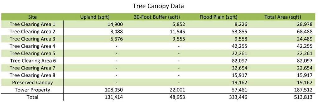
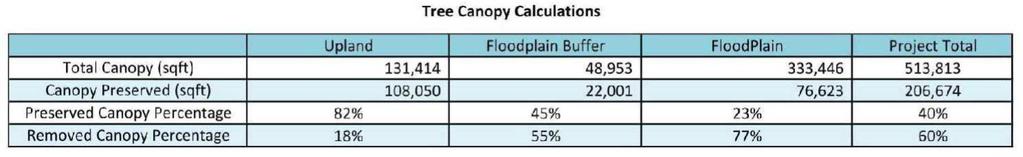
6 Addendum No 2. Q&A and Construction Document Changes Page 6 Contract Document Changes The following are changes and clarifications to the drawings or specifications and shall hereby be made part of and shall be attached to the subject Contract Documents. Reference attached specifications and drawing revisions: Specifications (6 pages): Add Specification for Pavement Markings. Page number and insertion of contract document will be provided at contract award. Drawings (1 sheet): Non landscape/clearing amended sheets will not be provided with this amendment. The answers that impact drawings mentioned in the Q&A above will be amended and provided upon contract award. Sheet T6 1. Tree General Notes and Calculations added Mitigation Calcs and Notes. See Attached Revised Specifications and Drawings

7 666 Item 666 Retroreflectorized Pavement Markings 1. DESCRIPTION 2. MATERIALS Furnish and place retroreflectorized, non-retroreflectorized (shadow) and profile pavement markings Type I Marking Materials. Furnish in accordance with DMS-8220, Hot Applied Thermoplastic. Furnish pavement marking material used for Type I profile markings and shadow markings that have been approved by the Construction Division, and in accordance with DMS-8220, Hot Applied Thermoplastic Type II Marking Materials. Furnish in accordance with DMS-8200, Traffic Paint Glass Traffic Beads. Furnish drop-on glass beads in accordance with DMS-8290, Glass Traffic Beads or as approved. Furnish a double-drop of Type II and Type III drop-on glass beads where each type bead is applied separately in equal portions (by weight), unless otherwise approved. Apply the Type III beads before applying the Type II beads Labeling. Use clearly marked containers that indicate color, mass, material type, manufacturer, and batch number. 3. EQUIPMENT 3.1. General Requirements. Use equipment that: is maintained in satisfactory condition, meets or exceeds the requirements of the National Board of Fire Underwriters and the Texas Railroad Commission for this application, applies beads by an automatic bead dispenser attached to the pavement marking equipment in such a manner that the beads are dispensed uniformly and almost instantly upon the marking as the marking is being applied to the road surface. The bead dispenser must have an automatic cut-off control, synchronized with the cut-off of the pavement marking equipment, has an automatic cut-off device with manual operating capabilities to provide clean, square marking ends, is capable of producing the types and shapes of profiles specified, and can provide continuous mixing and agitation of the pavement marking material. The use of pans, aprons, or similar appliances which the die overruns will not be permitted for longitudinal striping applications. Provide a hand-held thermometer capable of measuring the temperature of the marking material when applying Type I material. When pavement markings are required to meet minimum retroreflectivity requirements on the plans: Use a mobile retroreflectometer approved by the Construction Division and certified by the Texas A&M Transportation Institute Mobile Retroreflectometer Certification Program. Use a portable retroreflectometer that: uses 30-meter geometry and meets the requirements described in ASTM E1710; has either an internal global positioning system (GPS) or the ability to be linked with an external GPS with a minimum accuracy rating of 16 ft. 5 in., in accordance with the circular error probability 821
8 666 (CEP) method (CEP is the radius of the circle with its origin at a known position that encompasses 50% of the readings returned from the GPS instrument); can record and print the GPS location and retroreflectivity reading for each location where readings are taken Material Placement Requirements. Use equipment that can place: at least 40,000 ft. of 4-in. solid or broken non-profile markings per working day at the specified thickness; at least 15,000 ft. of solid or broken profile pavement markings per working day at the specified thickness; linear non-profile markings up to 8 in. wide in a single pass; non-profile pavement markings other than solid or broken lines at an approved production rate; a centerline and no-passing barrier-line configuration consisting of 1 broken line and 2 solid lines at the same time to the alignment, spacing, and thickness for non-profile pavement markings shown on the plans; solid and broken lines simultaneously; white line from both sides; lines with clean edges, uniform cross-section with a tolerance of ±1/8 in. per 4 in. width, uniform thickness, and reasonably square ends; skip lines between 10 and 10-1/2 ft., a stripe-to-gap ratio of 10 to 30, and a stripe-gap cycle between 39-1/2 ft. and 40-1/2 ft., automatically; beads uniformly and almost instantly on the marking as the marking is being applied; beads uniformly during the application of all lines (each line must have an equivalent bead yield rate and embedment); and double-drop bead applications using both Type II and Type III beads from separate independent bead applicators, unless otherwise approved by the Engineer. 4. CONSTRUCTION Place markings before opening to traffic unless short-term or work zone markings are allowed General. Obtain approval for the sequence of work and estimated daily production. Minimize interference to roadway operations when placing markings on roadways open to traffic. Use traffic control as shown on the plans or as approved. Protect all markings placed under open-traffic conditions from traffic damage and disfigurement. Establish guides to mark the lateral location of pavement markings as shown on the plans or as directed, and have guide locations verified. Use material for guides that will not leave a permanent mark on the roadway. Apply markings on pavement that is completely dry and passes the following tests: Type I Marking Application Place a sample of Type I marking material on a piece of tarpaper placed on the pavement. Allow the material to cool to ambient temperature, and then inspect the underside of the tarpaper in contact with the pavement. Pavement will be considered dry if there is no condensation on the tarpaper. Type II Marking Application Place a 1-sq. ft. piece of clear plastic on the pavement, and weight down the edges. The pavement is considered dry if, when inspected after 15 min., no condensation has occurred on the underside of the plastic. Apply markings: that meet the requirements of Tex-828-B, 822
9 that meet minimum retroreflectivity requirements when specified on the plans (applies to Type I markings only), using widths and colors shown on the plans, at locations shown on the plans, in proper alignment with the guides without deviating from the alignment more than 1 in. per 200 ft. of roadway or more than 2 in. maximum, without abrupt deviations, free of blisters and with no more than 5% by area of holes or voids, with uniform cross-section, density and thickness, with clean and reasonably square ends, that are retroreflectorized with drop-on glass beads, and using personnel skilled and experienced with installation of pavement markings. Remove all applied markings that are not in alignment or sequence as stated on the plans, or in the specifications, at the Contractor s expense in accordance with Item 677, Eliminating Existing Pavement Markings and Markers, except for measurement and payment Surface Preparation. Prepare surfaces in accordance with this Section unless otherwise shown on the plans Cleaning for New Asphalt Surfaces and Retracing of All Surfaces. Air blast or broom the pavement surface for new asphalt surfaces (less than 3 years old) and for retracing of all surfaces to remove loose material, unless otherwise shown on the plans. A sealer for Type I markings is not required unless otherwise shown on the plans Cleaning for Old Asphalt and Concrete Surfaces (Excludes Retracing). Clean old asphalt surfaces (more than 3 years old) and all concrete surfaces in accordance with Item 678, Pavement Surface Preparation for Markings, to remove curing membrane, dirt, grease, loose and flaking existing construction markings, and other forms of contamination Sealer for Type I Markings. Apply a pavement sealer to old asphalt surfaces (more than 3 years old) and to all concrete surfaces before placing Type I markings on locations that do not have existing markings, unless otherwise approved. The pavement sealer may be either a Type II marking or an acrylic or epoxy sealer as recommended by the Type I marking manufacturer unless otherwise shown on the plans. Follow the manufacturer s directions for application of acrylic or epoxy sealers. Clean sealer that becomes dirty after placement by washing or in accordance with Section , Cleaning for New Asphalt Surfaces and Retracing of All Surfaces, as directed. Place the sealer in the same configuration and color (unless clear) as the Type I markings unless otherwise shown on the plans Application. Apply markings during good weather unless otherwise directed. If markings are placed at Contractor option when inclement weather is impending and the markings are damaged by subsequent precipitation, the Contractor is responsible for all required replacement costs Type I Markings. Place the Type I marking after the sealer cures. Apply within the temperature limits recommended by the material manufacturer. Flush the spray head if spray application operations cease for 5 min or longer by spraying marking material into a pan or similar container until the material being applied is at the recommended temperature. Apply on clean, dry pavements passing the moisture test described in Section , General, and with a surface temperature above 50 F when measured in accordance with Tex-829-B Non-Profile Pavement Markings. Apply Type I non-profile markings with a minimum thickness of: in. (100 mils) for new markings and retracing water-based markings on surface treatments involving Item 316, Seal Coat,
10 in. (60 mils) for retracing on thermoplastic pavement markings, or in. (90 mils) for all other Type I markings. The maximum thickness for Type I non-profile markings is in. (180 mils). Measure thickness for markings in accordance with Tex-854-B using the tape method Profile Pavement Markings. Apply Type I profile markings with a minimum thickness of: in. (60 mil) for edgeline markings, or in. (90 mil) for gore and centerline/no-passing barrier line markings. In addition, at a longitudinal spacing indicated on the plans, the markings must be profiled in a vertical manner such that the profile is transverse to the longitudinal marking direction. The profile must not be less than 0.30 in. (300 mil) nor greater than 0.50 in. (500 mil) in height when measured above the normal top surface plane of the roadway. The transverse width of the profile must not be less than 3.25 in., and the longitudinal width not less than 1 in., when measured at the top surface plane of the profile bar. The profile may be either a 1 or 2 transverse bar profile. When the 2 transverse bar profile is used, the spacing between the bases of the profile bars must not exceed 0.50 in. The above transverse bar width is for each 4 in. of line width Type II Markings. Apply on surfaces with a minimum surface temperature of 50 F. Apply at least 20 gal. per mile on concrete and asphalt surfaces and at least 22 gal. per mile on surface treatments for a solid 4-in. line. Adjust application rates proportionally for other widths. When Type II markings are used as a sealer for Type I markings, apply at least 15 gal. per mile using Type II drop-on beads Bead Coverage. Provide a uniform distribution of beads across the surface of the stripe for Type I and Type II markings, with 40% to 60% bead embedment Retroreflectivity Requirements. When specified on the plans, Type I markings must meet the following minimum retroreflectivity values for edgeline markings, centerline or no passing barrier-line, and lane lines when measured any time after 3 days, but not later than 10 days after application: White markings: 250 millicandelas per square meter per lux (mcd/m 2 /lx) Yellow markings: 175 mcd/m 2 /lx 4.5. Retroreflectivity Measurements. Use a mobile retroreflectometer for projects requiring minimum retroreflectivity requirements to measure retroreflectivity for Contracts totaling more than 200,000 ft. of pavement markings, unless otherwise shown on the plans. For Contracts with less than 200,000 ft. of pavement markings or Contracts with callout work, mobile or portable retroreflectometers may be used at the Contractor s discretion Mobile Retroreflectometer Measurements. Provide mobile measurements averages for every 0.1 miles unless otherwise specified or approved. Take measurements on each section of roadway for each series of markings (i.e., edgeline, center skip line, each line of a double line, etc.) and for each direction of traffic flow. Measure each line in both directions for centerlines on two-way roadways (i.e., measure both double solid lines in both directions and measure all center skip lines in both directions). Furnish measurements in compliance with Special Specification, Mobile Retroreflectivity Data Collection for Pavement Markings, unless otherwise approved. The Engineer may require an occasional field comparison check with a portable retroreflectometer meeting the requirements listed above to ensure accuracy. Use all equipment in accordance with the manufacturer s recommendations and directions. Inform the Engineer at least 24 hr. before taking any measurements. A marking meets the retroreflectivity requirements if: the combined average retroreflectivity measurement for a one-mile segment meets the minimum retroreflectivity values specified, and no more than 30% of the retroreflectivity measurement values are below the minimum retroreflectivity requirements value within the one-mile segment. 824
11 666 The Engineer may accept failing one-mile segments if no more than 20% of the retroreflectivity measurements within that mile segment are below the minimum retroreflectivity requirement value. The one-mile segment will start from the beginning of the data collection and end after a mile worth of measurements have been taken; each subsequent mile of measurements will be a new segment. Centerlines with 2 stripes (either solid or broken) will result in 2 miles of data for each mile segment. Each centerline stripe must be tested for compliance as a stand-alone stripe. Restripe at the Contractor's expense with a minimum of in. (60 mils) of Type I marking if the marking fails retroreflectivity requirements. Take measurements every 0.1 miles a minimum of 10 days after this second application within that mile segment for that series of markings. If the markings do not meet minimum retroreflectivity after 10 days of this second application, the Engineer may require removal of all existing markings, a new application as initially specified, and a repeat of the application process until minimum retroreflectivity requirements are met Portable Retroreflectometer Measurements. Take a minimum of 20 measurements for each 1-mi. section of roadway for each series of markings (i.e., edgeline, center skip line, each line of a double line, etc.) and direction of traffic flow when using a portable reflectometer. Measure each line in both directions for centerlines on two-way roadways (i.e., measure both double solid lines in both directions and measure all center skip lines in both directions). The spacing between each measurement must be at least 100 ft. The Engineer may decrease the mileage frequency for measurements if the previous measurements provide satisfactory results. The Engineer may require the original number of measurements if concerns arise. Restripe once at the Contractor's expense with a minimum of in. (60 mils) of Type I marking material if the average of these measurements fails. Take a minimum of 10 more measurements after 10 days of this second application within that mile segment for that series of markings. Restripe again at the Contractor's expense with a minimum of in. (60 mils) of Type I marking material if the average of these measurements fall below the minimum retroreflectivity requirements. If the markings do not meet minimum retroreflectivity after this third application, the Engineer may require removal of all existing markings, a new application as initially specified, and a repeat of the application process until minimum retroreflectivity requirements are met Traffic Control. Provide traffic control, as required, when taking retroreflectivity measurements after marking application. On low volume roadways (as defined on the plans), refer to the figure, Temporary Road Closure in Part 6 of the Texas Manual on Uniform Traffic Control Devices for the minimum traffic control requirements. For all other roadways, the minimum traffic control requirements will be as shown on the Traffic Control Plan (TCP) standard sheets TCP (3-1) and TCP (3-2). The lead vehicle will not be required on divided highways. The TCP and traffic control devices must meet the requirements listed in Item 502, Barricades, Signs, and Traffic Handling. Time restrictions that apply during striping application will also apply during the retroreflectivity inspections except when using the mobile retroreflectometer unless otherwise shown on the plans or approved Performance Period. All markings must meet the requirements of this specification for at least 30 calendar days after installation. Unless otherwise directed, remove pavement markings that fail to meet requirements, and replace at the Contractor s expense. Replace failing markings within 30 days of notification. All replacement markings must also meet all requirements of this Item for a minimum of 30 calendar days after installation. 5. MEASUREMENT This Item will be measured by the foot; by each word, symbol, or shape; or by any other unit shown on the plans. Each stripe will be measured separately. 825
12 6. PAYMENT This is a plans quantity measurement item. The quantity to be paid is the quantity shown in the proposal unless modified by Article 9.2., Plans Quantity Measurement. Additional measurements or calculations will be made if adjustments of quantities are required. Acrylic or epoxy sealer, or Type II markings when used as a sealer for Type I markings, will be measured by the foot; by each word, symbol, or shape; or by any other unit shown on the plans. The work performed and materials furnished in accordance with this Item and measured as provided under Measurement will be paid for at the unit price bid for Pavement Sealer of the size specified, Retroreflectorized Pavement Markings of the type and color specified and the shape, width, size, and thickness specified as applicable, Retroreflectorized Pavement Markings with Retroreflective Requirements of the types, colors, sizes, widths, and thicknesses specified or Retroreflectorized Profile Pavement Markings of the various types, colors, shapes, sizes, and widths specified. This price is full compensation for application of pavement markings, materials, equipment, labor, tools, and incidentals. Surface preparation of new concrete and asphalt concrete pavements more than 3 years old, where no stripe exists, will be paid for under Item 678, Pavement Surface Preparation for Markings. Surface preparation of all other asphalt and old concrete pavement, except for sealing, will not be paid for directly but is subsidiary to this Item. Work zone pavement markings (Type II, paint and beads) used as a sealer for Type I markings (thermoplastic) will be paid for under Item 662, Work Zone Pavement Markings. If the Engineer requires that markings be placed in inclement weather, repair or replacement of markings damaged by the inclement weather will be paid for in addition to the original plans quantity

13
SPECIAL PROVISION TO SPECIAL SPECIFICATION Reflectorized Pavement Markings with Retroreflective Requirements
 2004 Specifications CSJ 0072-05-084, etc. & 0017-04-039, etc. SPECIAL PROVISION TO SPECIAL SPECIFICATION 6110---022 Reflectorized Pavement Markings with Retroreflective Requirements For this project, Special
STATE OF OHIO DEPARTMENT OF TRANSPORTATION. SUPPLEMENTAL SPECIFICATION 817 SPRAY THERMOPLASTIC PAVEMENT MARKING April 15, 2011
 817.01 Description 817.02 Materials 817.03 Equipment 817.04 Surface Preparation 817.05 Application 817.06 Basis of Payment STATE OF OHIO DEPARTMENT OF TRANSPORTATION SUPPLEMENTAL SPECIFICATION 817 SPRAY
ITEM 644 THERMOPLASTIC PAVEMENT MARKING
 ITEM 644 THERMOPLASTIC PAVEMENT MARKING 644.01 Description 644.02 Materials 644.03 Equipment 644.04 Application 644.05 Layout and Premarking 644.06 Basis of Payment 644.01 Description. This work consists
KANSAS DEPARTMENT OF TRANSPORTATION SPECIAL PROVISION TO THE STANDARD SPECIFICATIONS, 1990 EDITION
 Sheet 1 of 5 KANSAS DEPARTMENT OF TRANSPORTATION SPECIAL PROVISION TO THE STANDARD SPECIFICATIONS, 1990 EDITION NOTE: This special provision is generally written in the imperative mood. The subject, "the
Appendix D Answers To Chapter Review Questions
 Appendix D Answers To Chapter Review Questions Chapter 1 Standard Practices 1. The purpose of pavement markings is to communicate information about the traveled roadway so motorists can safely reach their
C. For cold-applied tape, the pavement temperature shall be at least 70 F.
 SECTION 6100 - PAVEMENT MARKING (THERMOPLASTIC) PART 1 - GENERAL 1.01 SCOPE: This Section covers hot-applied, extruded thermoplastic and cold-applied tape for white and yellow pavement marking. Topics
SPECIAL SPECIFICATION 8582 All Weather Thermoplastic Pavement Markings
 2004 Specifications CSJ 0610-06-076, etc. 1. Description. SPECIAL SPECIFICATION 8582 All Weather Thermoplastic Pavement Markings A. This specification covers a reflectorized thermoplastic pavement striping
SECTION 58 PRECAST CONCRETE BOX CULVERT. This work consists of furnishing and installing Pre-cast Concrete Box Culverts.
 SECTION 58 PRECAST CONCRETE BOX CULVERT 58.1 DESCRIPTION A. General This work consists of furnishing and installing Pre-cast Concrete Box Culverts. B. Related Work Section 51 Section 52 Section 53 Section
DIVISION PAVEMENT MARKINGS AND MARKERS
 DIVISION 61 66 PAVEMENT MARKINGS AND MARKERS 66.01 SCOPE: The purpose of these specifications is to describe the minimum requirements of the City of Chesapeake for pavement markings and shall be in addition
IGGA Guide Specification: Dowel Bar Retrofit (DBR) Introduction
 Introduction") IGGA Guide Specification: Dowel Bar Retrofit (DBR) Introduction This standard developed by the International Grooving and Grinding Association (IGGA) specifies the procedures for construction of dowel
IGGA Guide Specification: Dowel Bar Retrofit (DBR) Introduction This standard developed by the International Grooving and Grinding Association (IGGA) specifies the procedures for construction of dowel
SUPPLEMENTAL SPECIFICATION SINGLE COMPONENT HYBRIDIZED POLYMER PAVEMENT MARKINGS
 July 1, 016 SUPPLEMENTAL SPECIFICATION SINGLE COMPONENT HYBRIDIZED POLYMER PAVEMENT MARKINGS 66.1 6.1 Description 1 66.1 This section contains specifications for the materials, equipment, construction,
Section 7 Specification 7.2 Painted Roadway Lines TABLE OF CONTENTS
 TABLE OF CONTENTS 7.2 PAINTED ROADWAY LINES... 1 7.2.1 GENERAL... 1 7.2.1.1 Description... 1 7.2.1.2 Contractor Quality Control Inspection Plan... 1 7.2.2 MATERIALS... 1 7.2.3 EQUIPMENT... 1 7.2.3.1 General...
Section 914. JOINT AND WATERPROOFING MATERIALS
 914.01 Section 914. JOINT AND WATERPROOFING MATERIALS 914.01. General Requirements. Joint and waterproofing material for use in concrete construction must meet the requirements of this section. 914.02.
REQUEST FOR PROPOSALS
 REQUEST FOR PROPOSALS PROJECT: Painting of the Signal Poles, Mast Arms and Decorative Bases OWNER: City of Goose Creek, Department of Public Works RECEIPT OF PROPOSALS: Separate sealed proposals for the
SUPPLEMENTAL SPECIFICATION. PROFILE ROAD MARKING SYSTEM South Carolina Department of Transportation
 April 1, 2011 SUPPLEMENTAL SPECIFICATION PROFILE ROAD MARKING SYSTEM South Carolina Department of Transportation GENERAL The object of this specification is to describe a profile, (raised shape) marking
Item P-620 Runway and Taxiway Marking
 Item P-620 Runway and Taxiway Marking DESCRIPTION 620-1.1 This item shall consist of the preparation and painting of numbers, markings, and stripes on the surface of runways, taxiways, and aprons, in accordance
1.1 RELATED DOCUMENTS
 SECTION 050505 -BEVEL RAIL ENDS PART 1- GENERAL 1.1 RELATED DOCUMENTS A. Drawings and general provisions of the contract, including General and Supplementary Conditions and Division 01 Specification Sections
Item 550 Chain Link Fence
 Item Chain Link Fence 1. DESCRIPTION 2. MATERIALS Furnish, install, remove, repair, or replace chain link fence and gates. Furnish certification from the chain link fence materials manufacturer stating
SECTION STEEL LIGHTING STANDARDS. 1. Electrical conduit and fittings; Section
 02760-1 of 5 SECTION 02760 STEEL LIGHTING STANDARDS 02760.01 GENERAL A. Description Steel lighting standards shall include, but not necessarily be limited to, furnishing and installing steel lighting poles,
SPECIAL SPECIFICATION LIGHTNING PROTECTION SYSTEM
 2004 Specifications CSJ 3622-01-001, ETC. SPECIAL SPECIFICATION 8398 LIGHTNING PROTECTION SYSTEM 1. Description. This Special Specification governs the design and installation of Lightning Protection System
SECTION STRUCTURAL STEEL. A. PART A and DIVISION 1 of PART B are hereby made a part of this SECTION.
 SECTION 051200 PART 1 GENERAL 1.01 GENERAL REQUIREMENTS A. PART A and DIVISION 1 of PART B are hereby made a part of this SECTION. B. Examine all conditions as they exist at the project prior to submitting
SECTION BULLET- RESISTANT DOORS
 1 SECTION 08 3950 BULLET- RESISTANT DOORS PART 1- GENERAL 1.01 SUMMARY A. This Section Includes: 1. Bullet- resistant steel door and frame systems. 2. Door hardware for bullet- resistant steel door and
STATE OF OHIO DEPARTMENT OF TRANSPORTATION SUPPLEMENT 1073 PRECAST CONCRETE CERTIFICATION PROGRAM JULY 20, 2018
 STATE OF OHIO DEPARTMENT OF TRANSPORTATION SUPPLEMENT 1073 PRECAST CONCRETE CERTIFICATION PROGRAM JULY 20, 2018 1073.01 Program Overview 1073.02 Qualification 1073.03 Documentation Phase 1073.04 Documentation
For crossing under a railroad, contact the specific railroad company's engineering department.
 PAGE 330524-1 SECTION 330524 SPECIFIER: This section is for the underground installation of piping by directional drilling. When specifying this method of piping installation, care must be taken to ensure
DIVISION 1 - GENERAL REQUIREMENTS SECTION SUBMITTALS
 DIVISION 1 - GENERAL REQUIREMENTS SECTION 01300 - SUBMITTALS PART 1 - GENERAL 1.1 STIPULATIONS A. The section "Special Requirements" forms a part of this section by this reference thereto and shall have
INDEX TO CLAUSES PART 1 - GENERAL
 [PROJECT NAME] PAVEMENT INDEX TO CLAUSES PART 1 - GENERAL 1.1 Work Included 1.2 Related Sections 1.3 Reference Standards 1.4 Shop Drawings 1.5 Codes, Bylaws, Ordinances and Regulations 1.6 Certificates
Precast Concrete Pavement Background Concepts. Project 1517 FHWA, CTR & TxDOT Gary Graham November 15, 2001
 Precast Concrete Pavement Background Concepts Project 1517 FHWA, CTR & TxDOT Gary Graham November 15, 2001 Project Background CTR contracted by FHWA/TxDOT to investigate the feasibility of using precast
4.1. Foremen 4.2. Concrete plant manager 4.3. Concrete plant operator 4.4. Personnel performing saw cutting and joint sealing
 10-1. JOINTED PLAIN CONCRETE PAVEMENT GENERAL Summary This work includes constructing jointed plain concrete pavement. Comply with Section 40, "Concrete Pavement," of the Standard Specifications. Submittals
SPECIAL SPECIFICATION 7368 High Build Paint
 2004 Specifications CSJ 6163-41-001 1. Description. SPECIAL SPECIFICATION 7368 High Build Paint A. This work will consist of furnishing and installing a multiple component, retroreflective traffic marking
AMENDMENTS Manual of STANDARD SPECIFICATIONS. Adopted by Standard Specifications Committee. Amendment. No. 6. Published by
 AMENDMENTS to 2012 Manual of STANDARD SPECIFICATIONS Adopted by Standard Specifications Committee Amendment No. 6 Published by Utah LTAP Center Utah State University 8305 Old Main Hill Logan UT 84322-8205
SPECIAL SPECIFICATION Inch LED Traffic Signal Lamp Unit
 1993 Specifications SPECIAL SPECIFICATION 1201 12 Inch LED Traffic Signal Lamp Unit 1. Description. This specification describes the minimum acceptable design and performance requirements for a twelve
4. Metal roof jacks at penetrations and attachments
 - - - - - - - - - - - - - - - - - - - - - - - - - - - - - - - - - - - - - - - - - - - - - - - - - - - - - - - - - - - - - - - - - - - - - - SECTION 07 61 00 METAL SHINGLE ROOFING - - - - - - - - - - -
DMS-8220, Hot Applied Thermoplastic
 Overview Effective Date: August 2004 August 2007 (refer to 'Archived Versions' for previous versions). This Specification governs for the materials, composition, quality, sampling, and testing of thermoplastic
SPECIFICATIONS FOR THE MANUFACTURE AND DESIGN OF PRECAST THREE SIDED ARCH STRUCTURES, WINGWALLS AND HEADWALLS
 SPECIFICATIONS FOR THE MANUFACTURE AND DESIGN OF PRECAST THREE SIDED ARCH STRUCTURES, WINGWALLS AND HEADWALLS 1. DESCRIPTION THESE SPECIFICATIONS ARE FOR A PRECAST THREE SIDED ARCH STRUCTURE, HEADWALLS
1.0 DESCRIPTION. This specification covers steel snowplow blades with tungsten carbide inserts.
 (Page 1 of 5) (Rev.02-26-09) CARBIDE TIPPED SNOWPLOW BLADES MGS-91-01Q 1.0 DESCRIPTION. This specification covers steel snowplow blades with tungsten carbide inserts. 2.0 MATERIALS. 2.1 Steel. The blades
DOCUMENT ADDENDUM NO. 4. Issued to all Bidders: Date: October 14, Contract Name: Electrical Installation. Contract Number: C8410
 DOCUMENT 009104 - ADDENDUM NO. 4 Issued to all Bidders: Date: October 14, 2015 Contract Name: Electrical Installation Contract Number: C8410 This addendum forms a part of the Bid described above. The original
DMS-8290, Glass Traffic Beads
 Overview Effective Date: March 2001 April 2003. This specification shall govern for the materials, composition, quality, sampling, and testing of glass traffic beads. Bidders and/or Suppliers Requirements
Proposal PROJECT MANUAL P R O P E R T Y M A N A G E M E N T F A L L O N C O U N T Y. Baker, MT P.O. Box 846
 PROJECT MANUAL P R O P E R T Y M A N A G E M E N T F A L L O N C O U N T Y Proposal P.O. Box 846 Baker, MT 59313 P R E C A S T R E I N F O R C E D C O N C R E T E B O X C U L V E R T F O R W E S T M O
Opening date has been changes from October 29, 2014 to November 3, 2014.
 October 28, 2014 ADDENDUM #1 BL115-14 PAVEMENT MARKING SERVICES ON AN ANNUAL CONTRACT Opening date has been changes from October 29, 2014 to November 3, 2014. Q1. In Regards to Pavement Marking Eradication,
3 All Weather Paint. Product Bulletin January Second Drop Glass Beads
 3 All Weather Paint Product Bulletin January 2010 Description 3M All Weather Paint is a traffic paint system consisting of high-build waterborne paint and 3M bonded core elements. 3M all weather paint
SECTION PANELBOARDS
 PART 1 - GENERAL 1.1 DESCRIPTION SECTION 26 24 16 PANELBOARDS SPEC WRITER NOTE: Delete between // --- // if not applicable to project. Also, delete any other item or paragraph not applicable in the section
Product Bulletin July 2011
 3 Dry Elements Dry Standard/S Elements for Paint and Thermoplastic Pavement Markings Dry P Elements for 3M Polyurea Pavement Markings Dry E Elements for Epoxy Pavement Markings Dry M Elements for MMA Pavement
TABLE OF CONTENTS. 1.0 Scope. 2.0 References. 3.0 Definitions. 4.0 Submission and Design Requirements. 5.0 Materials 5.1 General 5.
 1.0 Scope 2.0 References 3.0 Definitions 4.0 Submission and Design Requirements 5.0 Materials 5.1 General 5.2 Marking 6.0 Equipment 7.0 Production 7.1 Steel Octagonal Poles 7.2 Base Plate 7.3 Top Cap 7.4
2016 Specification Treads, Base, Stringers and other Amenities Wausau Tile Precast Epoxy Terrazzo
 2016 Specification Treads, Base, Stringers and other Amenities 09400 Wausau Tile Precast Epoxy Terrazzo PART 1 - GENERAL 1.1 SUMMARY A. Perform all work required to complete, as indicated by the Contract
Item P-620 Runway and Taxiway Marking
 Item P-620 Runway and Taxiway Marking DESCRIPTION 620-1.1 This item shall consist of the preparation and painting of numbers, markings, and stripes on the surface of runways, taxiways, and aprons, in accordance
Traffic Line Painting and Other Pavement Markings
 Gateway to the 1000 Islands QUOTATION FOR: Traffic Line Painting and Other Pavement Markings QUOTATION CLOSING: May 23, 2013 QUOTATION NUMBER: RDS-2013-02 Submit completed quotations to: Quotation for
Standard Specifications
 Standard Specifications PART 1.00 GENERAL 1.01 DECRIPTION SECTION 02620 PRECAST REINFORCED CONCRETE SANITARY MANHOLES A. Work included: The Contractor shall furnish all labor, materials, equipment, and
ADDENDUM NO. 3 PROJECT: COURTLAND PUMP STATION CONTRACT: IFB NO COM.00030
 ADDENDUM NO. 3 PROJECT: COURTLAND PUMP STATION CONTRACT: IFB NO. 2018-008-COM.00030 To: Prospective Bidders of Record Date: January 8, 2019 The following changes, additions, revisions, and/or deletions
Edgerail Aluminum Bridge Railing System Specification & Installation Instructions
 Edgerail System Specification & Installation Instructions Hill & Smith, Inc 1000 Buckeye Park Road Columbus, Ohio 43207 Tel: 614-340-6294 Fax: 614-340-6296 www.hillandsmith.com Section A System Specification
SPECIAL SPECIFICATION 8802 Radio Communication Tower Inspection, Maintenance, and Repair
 2004 Specifications CSJ 6228-45-001 & 6248-06-001 SPECIAL SPECIFICATION 8802 Radio Communication Tower Inspection, Maintenance, and Repair 1. Description. This specification describes service to provide
CONSTRUCTION SPECIFICATION FOR PRECAST REINFORCED CONCRETE BOX CULVERTS AND BOX SEWERS
 ONTARIO PROVINCIAL STANDARD SPECIFICATION METRIC OPSS 422 MAY 1993 CONSTRUCTION SPECIFICATION FOR PRECAST REINFORCED CONCRETE BOX CULVERTS AND BOX SEWERS 422.01 SCOPE 422.02 REFERENCES 422.03 DEFINITIONS
3400 Tectura Designs Precast Concrete
 3400 Tectura Designs Precast Concrete PART 1 - GENERAL 1.1 SUMMARY A. Perform all work required to furnish and complete the proper installation of precast concrete. B. Types of Precast Concrete work include:
PORT OF ST. HELENS SCAPPOOSE INDUSTRIAL AIRPARK PARALLEL TAXIWAY B RELOCATON AIP PROJECT ADDENDUM NO. 1
 PORT OF ST. HELENS SCAPPOOSE INDUSTRIAL AIRPARK PARALLEL TAXIWAY B RELOCATON AIP PROJECT 3-41-0056-024-2018 ADDENDUM NO. 1 Addendum No. 1 hereby amends the contract documents and drawings for the Scappoose
SPECIAL PROVISION Description of Project, Scope of Contract and Sequence of Work
 2004 Specifications CSJ 0110-04-166 SPECIAL PROVISION 000--363 Description of Project, Scope of Contract and Sequence of Work 1. General. The work to be performed on this project consists of furnishing,
SECTION STRUCTURAL STEEL FRAMING PART 1 - GENERAL 1.1 RELATED DOCUMENTS
 SECTION 05 12 00 - STRUCTURAL STEEL FRAMING PART 1 - GENERAL 1.1 RELATED DOCUMENTS A. Drawings and general provisions of the Contract, including General and Supplementary Conditions and Division 01 Specification
Re-Roofing Policy SPECIAL REQUIREMENTS AND NOTES
 CITY OF MANTECA COMMUNITY DEVELOPMENT DEPARTMENT 1001 West Center Street Manteca, CA 95337 FAX (209) 923-8949 Building Safety Division (209) 456-8550 Planning Division (209) 456-8500 Public Works/Engineering
Portable retroreflectometers and structured pavement markings
 TECHNICAL NOTE RS104 Portable retroreflectometers and structured pavement markings Introduction This paper addresses the question: "can portable retroreflectometers be used to measure the retroreflection
5/16" Flange nut. Bolt Keeper Plate (8" Sq. SYS.) (3) 1/2" x 3" Hex head connector zinc plated bolt w/ washers and nut. Anchor 3" sq. 7 Ga.
 (3) 1/2 x 3 Hex head connector zinc plated bolt w/ washers and nut. Anchor 3 sq. 7 Ga.") 2 1/2" x 2 1/2" x 10 Ga. 6" 5" 4" Variable Slipbase (8" Sq. SYS.) 5/16 Corner Bolt W/ nut 5/16" Flange nut Stub Insert (8" Sq. SYS.) Bolt Keeper Plate (8" Sq. SYS.) (3) 1/2" x 3" Hex head connector zinc
2 1/2" x 2 1/2" x 10 Ga. 6" 5" 4" Variable Slipbase (8" Sq. SYS.) 5/16 Corner Bolt W/ nut 5/16" Flange nut Stub Insert (8" Sq. SYS.) Bolt Keeper Plate (8" Sq. SYS.) (3) 1/2" x 3" Hex head connector zinc
Anticipated schedule, Page 2. Change the Contract Term from 635 Days to be 1,127 Days.
 This addendum is hereby made part of the Request for Bid for the above-named project and shall be taken into consideration by all firms preparing a submittal on this project. Acknowledge receipt of this
SECTION 025 INDUSTRIAL PAINTING
 SECTION 025 INDUSTRIL PINTING Industrial painting, including all necessary preparation and application, except as modified in this Section, shall conform to the recommendations of the manufacturer of the
SYMBOL DESCRIPTION TRAFFIC CONTROL SIGN TYPE III BARRICADE = IMPACT ATTENUATOR STRIPING KEY TRIANGLE - PAINT PLASTIC MARKING 1ST DIGIT WIDTH 4" OR 8"
 TES & GUIDELINES TRAIC CONTROL DEVICES & SYMBOLS LEGEND INDEX 2. GENERAL IRMATION: THE CONTRACTOR SHALL URNISH, INSTALL AND MAINTAIN THE DEVICES IN THIS TRAIC CONTROL PLAN UNLESS OTHERWISE TED. IELD CONDITIONS
MPA Project No. M545-C2 Project Title: New Berth 10 Project - Phase II Location: Conley Terminal, South Boston, Massachusetts
 MPA Project No. M545-C2 Project Title: New Berth 10 Project - Phase II Location: Conley Terminal, South Boston, Massachusetts RESPONSES TO QUESTIONS and/or RFI s # 3 Date: 09/14/18 The attention of Contractors
Dowel Bar Alignment and Location for Placement by Mechanical Dowel Bar Insertion
 Dowel Bar Alignment and Location for Placement by Mechanical Dowel Bar Insertion January 7, 2013 Scope, Background and Applicability This guide specification is directly applicable to 18 in. (457 mm) long,
A. Extent of structural precast concrete work is shown on drawings and in schedules.
 SECTION 03 41 00 - STRUCTURAL PRECAST CONCRETE PART 1 GENERAL 1.1 RELATED DOCUMENTS A. Drawings and general provisions of Contract, including General and Supplementary Conditions and Division 1 specification
Product Guide Specification
 Shield Casework February 2014 3421 Merriam Lane Overland Park, Kansas 66203 Phone 913-744-2183 Fax 913-384-3477 Website www.shieldcasework.com E-mail info@shieldcasework.com Product Guide Specification
Liquid Pavement Marking Series 1200
 Liquid Pavement Marking Series 1200 Product Bulletin 1200 October 2009 Replaces PB 1200 dated March 2004 Description M Liquid Pavement Marking (LPM) Series 1200 is designed for use on roadways and highways
B. Shop Drawings: Include elevations, door edge details, frame profiles, metal thicknesses, preparations for hardware, and other details.
 SECTION 081113 - HOLLOW METAL DOORS AND FRAMES PART 1 - GENERAL 1.1 SUMMARY A. Section Includes: 1. Standard hollow metal doors and frames. 1.2 SUBMITTALS A. Product Data: For each type of product indicated.
REVISION #1. Section. fire alarm B. C. the hot. intent of. required. manufacturer. materials. C. Warranty
 HOT AISLE CONTAINMENT SYSTEM (HACS) REVISION #1 PART 1 - GENERAL 1.1 RELATED DOCUMENTS A. B. C. Drawings and general provisions of the Contract, including General and Supplementary. Conditions apply to
SECTION MANHOLES
 SECTION 33 05 13 MANHOLES PART 1 GENERAL 1.01 SECTION INCLUDES A. CONTRACTOR shall furnish and install precast concrete manhole base, sections, adjusting rings, steps, and manhole ring and cover, complete.
SECTION CABLE TRAYS FOR COMMUNICATIONS SYSTEMS
 SECTION 270536 - CABLE TRAYS FOR COMMUNICATIONS SYSTEMS PART 1 - GENERAL 1.1 RELATED DOCUMENTS A. Drawings and general provisions of the Contract, including General and Supplementary Conditions and Division
D. Thermally Sprayed Metallic Coating (Flame Spray): STD SPEC
: STD SPEC") STANDARD SPECIFICATION SECTION 05121 MISCELLANEOUS METALWORK PART 1 - GENERAL 1.01 DESCRIPTION This section includes materials, fabrication, and installation of structural steel, connecting bolts, pipes,
STANDARD SPECIFICATION SECTION 05121 MISCELLANEOUS METALWORK PART 1 - GENERAL 1.01 DESCRIPTION This section includes materials, fabrication, and installation of structural steel, connecting bolts, pipes,
SECTION 39 - MANHOLES TABLE OF CONTENTS
 SECTION 39 - MANHOLES TABLE OF CONTENTS Section Page 39-1 GENERAL... 39.1 39-2 PRECAST CONCRETE MANHOLES... 39.1 39-2.01 Precast Concrete Sewer Manholes... 39.1 39-2.02 Precast Concrete Storm Drain Manholes...
Heavy and Medium Duty Fire Doors
 Heavy and Medium Duty Fire Doors 10 06.06.2011 Add. Section 1.4. JES VK 09 14.12.2009 New doc. Frontpage JES VK 08 29.11.2006 Page 8 and 13 revised JES VK 07 08.11.2006 Page 15 revised JES VK 06 08.03.2005
WATER MAIN ALONG ENTRANCE TO ENCINO PS / HWY 281 TO ENCINO TANK Solicitation Number: CO Job No.:
 WATER MAIN ALONG ENTRANCE TO ENCINO PS / HWY 281 TO ENCINO TANK Solicitation Number: CO-00111 Job No.: 16-7003 To Respondent of Record: ADDENDUM 2 July 5, 2017 This addendum, applicable to work referenced
SPECIAL SPECIFICATION 7415 All Weather Paint
 2004 Specifications CSJ 6182-27-001 1. Description. SPECIAL SPECIFICATION 7415 All Weather Paint A. This work will consist of furnishing and installing a multiple component, retroreflective traffic marking
CITY OF TOMBALL. Section FIRE HYDRANTS 1.01 SECTION INCLUDES. A. Fire hydrants. B. Adjustment of fire hydrants and gate valves.
 Section 02520 PART 1 G E N E R A L 1.01 SECTION INCLUDES A. Fire hydrants. B. Adjustment of fire hydrants and gate valves. 1.02 MEASUREMENT AND PAYMENT A. Unit Prices. 1. Payment is on a unit price basis
B. Shop Drawings: Include elevations, door edge details, frame profiles, metal thicknesses, preparations for hardware, and other details.
 SECTION 081113 - HOLLOW METAL DOORS AND FRAMES PART 1 - GENERAL 1.1 SUMMARY A. Section Includes: 1. Standard hollow metal doors and frames. 1.2 SUBMITTALS A. Product Data: For each type of product indicated.
SECTION 1085 PRECAST REINFORCED CONCRETE BOX CULVERT
 1085.1 1085.2(k) SECTION 1085 PRECAST REINFORCED CONCRETE BOX CULVERT 1085.1 DESCRIPTION This work is the manufacture, storage, delivery, installation, and assembly of precast reinforced concrete box culvert
STRUCTURED PAVEMENT MARKINGS 90 TH ANNUAL TRANSPORTATION SHORT COURSE TRAFFIC OPERATIONS SESSION I PRESENTED BY HERBERT BICKLEY, P.E.
 STRUCTURED PAVEMENT MARKINGS 90 TH ANNUAL TRANSPORTATION SHORT COURSE TRAFFIC OPERATIONS SESSION I PRESENTED BY HERBERT BICKLEY, P.E. PRODUCTS AND PROCESSES Structured markings have been in use for some
OPERATING PAVEMENT PROFILOGRAPH AND EVALUATING PROFILES
 Test Procedure for OPERATING PAVEMENT PROFILOGRAPH AND EVALUATING PROFILES Texas Department of Transportation TxDOT Designation: Tex-1000-S Effective Date: August 1999 1. SCOPE 1.1 This method covers the
Facility Services Subgroup Preface for Divisions 21` through 28
 Facility Services Subgroup Preface for Divisions 21` through 28 1.1 EXECUTIVE SUMMARY A. This document provides standards for the Consultants and Contractors producing mechanical and electrical design
CHAPTER 1: TITLE SHEET and GENERAL LAYOUT
 CHAPTER 1: TITLE SHEET and GENERAL LAYOUT AREA OF ENVIRONMENTAL SENSITIVITY It is important to show the areas of environmental sensitivity in the plan to make sure these areas are not impacted. These locations
SPECIFICATIONS FOR THE INSTALLATION OF CONDUIT SYSTEMS IN RESIDENTIAL SUBDIVISIONS. Notification of Completed Conduit Sections
 SPECIFICATIONS FOR THE INSTALLATION OF CONDUIT SYSTEMS IN RESIDENTIAL SUBDIVISIONS Section 1 Definitions 2 Scope of Work 3 Extent of Work 4 Inspection and Performance of Work 5 Trenching 6 Duct Installation
MATERIAL COMBINATION NUMBER 2: Corrosive environment requiring harder, wear-resistant seating faces and resistance to dezincification.
 Cast Iron Slide Gates Spec Sheet General The contractor shall furnish and install the following cast iron slide gate assemblies as listed on the Gate Schedule and detailed on the manufacturer s drawings.
A. Action Submittals: Written and graphic information that requires Architect's responsive action.
 SECTION 01330 - SUBMITTAL PROCEDURES PART 1 - GENERAL 1.1 RELATED DOCUMENTS A. Drawings and general provisions of the Contract, including General and Supplementary Conditions and other Division 1 Specification
RESIDENTIAL ROOFS ADDENDUM NUMBER ONE. August 28, 2017
 RESIDENTIAL ADDENDUM NUMBER ONE August 28, 2017 The following additions to, deletions from, and clarifications of the Contract Documents govern insofar as they apply and shall take precedence over those
Section Meetings Section Material and Equipment. None Required
 January 2000 Page 1 of 8 PART 1 GENERAL 1.01 OTHER CONTRACT DOCUMENTS 1.02 DESCRIPTION OF WORK 1.03 RELATED WORK PART 2 PRODUCTS The General Conditions of the Contract, General Requirements and Supplemental
SECTION PRECAST CONCRETE SECTIONAL MANHOLES
 SECTION 02545 PRECAST CONCRETE SECTIONAL MANHOLES PART 1 - GENERAL 1.01 SUMMARY A. Section Includes: 1. Precast reinforced concrete cylindrical sectional manholes, complete with openings, inserts, hardware,
SECTION METAL FABRICATIONS
 SECTION 05100 PART 1 - GENERAL 1.01 DESCRIPTION A. Section includes specifications for metal fabrications, including minimum requirements for fabricator, and galvanizing. 1.02 REFERENCE STANDARDS A. ASTM
JEFFERSON LAB TECHNICAL ENGINEERING & DEVELOPMENT FACILITY (TEDF ONE) Newport News, Virginia
 Newport News, Virginia") BULLETIN NO. 6 TO THE PLANS AND SPECIFICATIONS FOR JEFFERSON LAB TECHNICAL ENGINEERING & DEVELOPMENT FACILITY (TEDF ONE) Newport News, Virginia EwingCole Architects.Engineers.Interior Designers.Planners
BULLETIN NO. 6 TO THE PLANS AND SPECIFICATIONS FOR JEFFERSON LAB TECHNICAL ENGINEERING & DEVELOPMENT FACILITY (TEDF ONE) Newport News, Virginia EwingCole Architects.Engineers.Interior Designers.Planners
East Central College
 SECTION 013300 - SUBMITTAL PROCEDURES PART 1 - GENERAL 1.1 RELATED DOCUMENTS A. Drawings and general provisions of the Contract, including General and Supplementary Conditions and other Division 01 Specification
A. Action Submittals: Written and graphic information that requires Engineer's responsive action.
 SECTION 01330 - SUBMITTAL PROCEDURES PART 1 - GENERAL 1.1 RELATED DOCUMENTS A. Drawings and general provisions of the Contract, including General and Supplementary Conditions and other Division 1 Specification
CITY OF PITTSBURG ENGINEERING DEPARTMENT CONTRACT NO A WATER TREATEMENT PLANT CAPITAL IMPROVEMENTS PHASE 1A ADDENDUM #1 FENCE AND DITCH AUGUST
 CITY OF PITTSBURG ENGINEERING DEPARTMENT CONTRACT NO. 2012-16A WATER TREATEMENT PLANT CAPITAL IMPROVEMENTS PHASE 1A ADDENDUM #1 FENCE AND DITCH AUGUST 2014 CHAIN LINK FENCE SPECIFICATIONS Chain link fence,
StormTrap Guide Specification. StormTrap SingleTrap on Pad Foundation Groundwater BELOW Invert Revised 11/21/18
 StormTrap Guide Specification StormTrap SingleTrap on Pad Foundation Groundwater BELOW Invert Revised 11/21/18 This product guide specification is written according to the Construction Specifications Institute
GUIDELINE SPECIFICATIONS
 GUIDELINE SPECIFICATIONS GORDON MILLENNIUM DECORATIVE METAL COLUMN COVERS DIVISION 05 7500 or DIVISION 09 2000 Note To Specifier: Column Covers are a finished, decorative product and should be installed
American Institute of Timber Construction 7012 South Revere Parkway Suite 140 Centennial, CO Phone: 303/ Fax: 303/
 American Institute of Timber Construction 7012 South Revere Parkway Suite 140 Centennial, CO 80112 Phone: 303/792-9559 Fax: 303/792-0669 404.1. SCOPE STANDARD FOR RADIALLY REINFORCING CURVED GLUED LAMINATED
SECTION SUBMITTAL PROCEDURES PART 1 - GENERAL 1.1 RELATED DOCUMENTS
 SECTION 01 33 00 - SUBMITTAL PROCEDURES PART 1 - GENERAL 1.1 RELATED DOCUMENTS A. Drawings and general provisions of the Contract, including General and Supplementary Conditions and other Division 01 Specification
SECTION SUBMITTAL PROCEDURES
 SECTION 01330 - SUBMITTAL PROCEDURES PART 1 - GENERAL 1.1 RELATED DOCUMENTS A. Drawings and general provisions of the Contract, including General and Supplementary Conditions and other Division 1 Specification
Bid No :01 Exterior Roynon Elementary & La Verne Heights (Alternate #1) SCOPE OF WORK
 SCOPE OF WORK") Part I. General 1.01 General Conditions SCOPE OF WORK A. The contractor shall provide all paint, labor, tools and supplies to perform a complete repaint of all exterior/interior surfaces of the building,
Part I. General 1.01 General Conditions SCOPE OF WORK A. The contractor shall provide all paint, labor, tools and supplies to perform a complete repaint of all exterior/interior surfaces of the building,
SECTION CABLE TRAYS
 SECTION 16139 CABLE TRAYS PART 1 - GENERAL 1.1 RELATED DOCUMENTS A. Drawings and general provisions of the Contract, including General and Supplementary Conditions and Division 1 Specification Sections,