SECTION 3 SUBMISSION REQUIREMENTS
|
|
|
- Emery Franklin
- 6 years ago
- Views:
Transcription
1 SECTION 3 SUBMISSION REQUIREMENTS Table of Contents Page No 3.1 GENERAL COORDINATION WITH OUTSIDE AGENCIES PRELIMINARY DESIGN FINAL DESIGN GENERAL PHASE A SUBMISSION PHASE B SUBMISSION PHASE C SUBMISSION Pre-Phase C Phase C Submission PHASE D SUBMISSION POST-PHASE D SERVICES Addenda Engineer s Estimate Evaluation of Bid Results Changes-of-Plan Shop Drawing Review Requests for Information As-Built Plans Lighting System CONSTRUCTABILITY REPORT PURPOSE AND INTENT WHEN TO SUBMIT THE REPORT GENERAL REPORT FORMAT Introduction Construction Methods Existing Structure Demolition Limits of Traffic Effects Specialty Equipment or Water Work Construction Staging and Storage Areas Approximate Construction Schedule March
2 List of Exhibits Page No Exhibit 3-1 Phase A Checklist... 9 Exhibit 3-2 Phase B Checklist Exhibit 3 3(a) Pre-Phase C Checklist Exhibit 3 3(b) Phase C Checklist Exhibit 3-4 Phase D Checklist Exhibit 3-5 Design Element Modification Request Exhibit 3-6 Summary of Permit Requirements Exhibit 3-7 Environmental Permits Exhibit 3-8 Shop and Working Drawings Exhibit 3-9 Material Acceptance Criteria Matrix March
3 3.1 GENERAL SECTION 3 SUBMISSION REQUIREMENTS A project may be a single construction contract, or it may consist of multiple construction contracts within a project or a Design Section. Generally, all projects have a preliminary and final design. However, if in the Authority s Engineering Department opinion a preliminary design phase is unnecessary, such as a deck repair project, they may direct that a project proceed directly to the later stages of final design. In the following pages, the number of sets of plans required for submittal with each phase submittal is given. These are approximate numbers anticipated to be required for complete plan review; however, the Authority s Engineering Department may at times find it necessary to revise the number of sets required for any phase submittal. The Engineer shall confirm the number of sets required with the Authority s Project Manager three (3) weeks prior to each submission. When a phase review is completed, one (1) or more set(s) of contract documents may be returned to the Engineer, which will reflect the comments of the reviewers noted in red. When the succeeding Phase is submitted, the Engineer is to include these comment sets as part of the submission. Every comment shown on the sets is to be addressed. No comments are to be ignored or dismissed, but they all must be acknowledged with a check mark signifying agreement, or an explanation or answer given. All of the Engineer s responses to the comments are to be green pencil and written directly on the comment set. Review periods will be established on a project-by-project basis. Generally, the Authority s Engineering Department requires two (2) weeks to review a phase submission, and the Engineer will be permitted a two (2) week period to prepare a rebuttal to the comments. 3.2 COORDINATION WITH OUTSIDE AGENCIES As part of their work in preparing contract plans, it will be necessary for the Engineer to meet with outside agencies as approved or as directed by the Authority s Engineering Department concerning such matters as the relocation or rearrangement of local roadways, utilities, sewerage works, etc. To keep the Authority s Engineering Department well informed regarding the progress of the plans and the commitments made by both sides during these discussions, the Engineer is to submit to the Authority s Engineering Department four (4) copies of a memorandum of record covering each meeting held with any outside agencies. The memoranda are to contain at least the following: Agency contacted and the reason for the meeting; the date and location of the meeting; list of persons in attendance with their titles and level of responsibility; topics discussed and solutions reached; criteria used for resolving problems such as: company policy, municipal ordinance, State Board of Health requirement, etc.; areas March
4 requiring Authority decisions; problems unresolved; and areas where betterments are involved and the extent to which the outside agency is aware of its participation. In addition, the Engineer is to submit to the Authority s Engineering Department four (4) copies of all correspondence both to and from these outside agencies in which approvals, concurrences or any commitments are made by either the Engineer or the outside agency. Four (4) copies of correspondence for receipt of transmission of plans, specifications, etc., to or from the Engineer, are also to be sent to the Authority s Engineering Department. 3.3 PRELIMINARY DESIGN Preliminary design studies are to be developed at either 1 =100 or 1 =200 scale, which will be used to establish preliminary horizontal and vertical alignment, stormwater management characteristics, interchange configurations and local road treatments. During this stage, preliminary cost estimates and tentative maintenance and protection of traffic schemes will be initiated, and an approximate right of way impact identified. Studies are to be shown on reproducible topographic or aerial photo base maps, as directed by the Authority s Engineering Department and are to be accurately drawn in Computer Aided Design (CAD) software. Where required or warranted, alternative studies are to be made. The studies may consist of, but need not be limited to, horizontal and vertical alignment shifts, channelization alternatives, alternative interchange configurations and right of way comparisons. In all alternative studies, the presentation is to be similar to the remainder of the project and for each alternative, the Engineer will prepare a cost estimate, a list of advantages and disadvantages and their recommendations. When the preliminary plans are submitted for review and approval, the submission shall consist of the following: 1. Three (3) sets of prints and a printable document format (PDF) file of the plans and profiles. A minimum of one (1) set shall be colored, and additional colored sets may be requested by the Authority s Engineering Department, showing the proposed construction in accordance with the following legend: Water and Waterways aqua Authority Roadways yellow mainline, ramps, U-turns, etc. Authority Shoulders brown Local Roads green Right of Way red Structure Outlines black Slope Lines dashed Cut brown Fill green Parks, Hatched green March
5 Mileposts, Outlined black 2. Alternatives studied including alignments, environmental concerns, schedule considerations and cost estimates. 3. Project cost estimate and contract breakdown with respective costs. 4. A statement describing the project; any problem areas warranting detailed studies during a subsequent phase; meetings held with various agencies to resolve problems such as roadway widths, etc.; brief construction sequence; estimated earthwork as to quantity of borrow or waste for the project; environmental and permit concerns and construction coordination with adjacent projects. 5. Typical sections showing lane dimensions, local roadway widths, grading criteria, median treatment, etc. 6. Show the proposed project and the approximate locations of existing utilities in plan with conflicts identified. 3.4 FINAL DESIGN General During the preparation of final design documents, interim phase submissions are to be made to the Authority s Engineering Department. These phase submissions are required at various stages in development to allow for review of the material first, for concept, subsequently for specifics and, finally, for completeness. The submissions are defined as follows: Phase A - graphical 1 = 50 or 1 = 30 scale plans - contract documents 35 percent complete. A single submission should cover an entire project or Design Section. Phase B - computed alignment - contract documents 70 percent complete. A separate submission is required for each construction contract within a project or Design Section. Phase C - complete plans, quantities, specifications, schedule and cost estimates - contract documents are 95 percent complete and subject to thorough review by the Authority s Engineering Department. A separate submission is required for each construction contract within a project or Design Section. Phase D complete plans and specifications revised in accordance with comments resulting from Phase C review. The Contract is 100 percent complete and ready for advertisement. A separate submission is required for each construction contract within a project or Design Section. However, when multiple construction contracts are required within a Design Section, or the environmental permitting encompasses multiple Design Sections, the Phase A submittal requirements may be modified at the direction of the Authority s Project Manager, to include more-detailed design. Such elements may include, but are not limited to, computed alignment, March
6 recommended foundation type(s), structural GP&E, completed drainage system, etc. In such instances, interim submissions, as directed by the Authority s Project Manager, will be required before the formal Phase A submission, which may include the computed alignment, stormwater management impacts, bridge type studies, etc. In the case of construction contracts involving Architecture / Buildings, Subsection 6B.7 of Section 6B (Structures Plan Preparation) of this Manual shall be referred to for modified submission requirements. All submission documents shall indicate the phase submittal and the date of the submission. The Design Phase schedule shall be maintained in CapEx, and as directed by the Authority s Project Manager. Electronic deliverables shall be uploaded to CapEx where indicated, or as directed by the Authority s Project Manager. Refer to the CapEx & Specifications Design Guidelines on the Authority s website for instructions Phase A Submission A Phase A submission is a graphical 1 =50 or 1 =30 scale horizontal alignment and graphical 1 =5 vertical and 1 =50 horizontal scale profiles. The minimum information required for a Phase A submission is as follows: 1. The submission shall consist of a complete electronic submission in PDF format and six (6) copies of all materials, with three (3) sets of plans colored in accordance with the color scheme noted for Preliminary Plans. One (1) or more sets will be returned to the Engineer with review comments in red, and there may be additional written comments in memorandum format. 2. The Engineer shall submit a Design Element Modification Request (Exhibit 3-5) to the Authority s Engineering Department listing all design elements that do not meet the minimum criteria, if there are any. Except in very specific cases with explicit justification, approval of modified design elements will not be granted. Back up shall be included detailing why a design element shall not be standard, including impacts and costs. If any specific design criteria is not met and appropriate approvals from the Authority s Engineering Department are not received, the submission will be rejected without further or complete review, and a resubmission will be required, at no additional cost to the Authority. 3. The alignment shall be at 1 =50 or 1 =30 scale. If 2 x 3 cut sheets are used, the same information as shown on these sheets is to be reproduced and the cut sheets are to be spliced together to form a manuscript. Large sheets shall be used in interchange areas in an attempt to show the full interchange on the fewest number sheets possible. 4. Alignments shall show all horizontal information, including roadway designations, stationing, station equations, normal pavement dimensions and cross slopes, pavement dimensions at beginning and end of transitions, radii, PC and PT locations, superelevation for each curve, slope line, existing property lines, proposed right of way lines, existing and proposed utility relocations and detours. March
7 5. Profiles shall show roadway designations, structures, stationing, grades, existing ground, proposed ground, minimum vertical clearances, complete vertical curve information including K values, ramp take-offs superimposed on mainline, mainline superimposed at ramp nose, physical noses, and in loops, the adjacent ramp profiles superimposed in concentric areas, superelevation, superelevation transitions, horizontal curve radii and the design speed. Profiles shall be at a scale of 1 =5 vertical and 1 = 50 horizontal. 6. Typical Sections are required for mainline roadways, ramps, local roads, access roads and any other roadway or parking lot areas. The sections shall include pavement make up, curb types, guide rail treatment, grading criteria, sidewalks, medians, barrier, etc. 7. A completed boring contract and special soils treatment recommendation submitted for approval. See Section 5 (Geotechnical Engineering) of this Manual for additional details as well as Pre-Phase A requirements. 8. State, County and Municipal agency approval, in writing, as to concurrence with the concept for all affected roadways as to proposed construction, maintenance, protection of traffic, and intent as to participation in betterments. 9. The roadway plans shall show existing property lines and proposed right of way lines and method of setting right of way. The Authority s Project Manager shall be informed of any unique situations or problem areas once identified. Right-of-Way documents required shall be in accordance with Section 8 (Right-of-Way) of this Manual. 10. Conceptual lighting plans and supporting documents prepared in accordance with Section 7 (Lighting and Power Distribution Systems) of the Design Manual. 11. Conceptual ITS plans prepared in accordance with Section 8 (ITS and Communications) of the Design Manual. 12. Show the existing utilities and the proposed project in plan with the utility conflicts identified. See Section 7 (Utility Installations, Relocations and Adjustments) of this Manual for additional information. 13. For Contracts with bridge structures, 8½ x 11 structure sketches shall be submitted for review and approval as soon as the necessary information is available (prior to the Phase A submission). See Section 6B (Structures Plan Preparation) of this Manual for additional information on this submission. 14. Provide the Authority s Engineering Department with a written confirmation of the structural maintenance jurisdiction. 15. Noise Barrier Report prepared in accordance with Section 2 (Structures Design) of the Design Manual. 16. Toll Plaza buildings typically require an Architect and close coordination with the Engineer. A detailed written list of activities to be completed shall be submitted identifying responsibilities and who shall complete them. March
8 See Section 11 (Facility Buildings and Toll Plazas) of the Design Manual for more information. 17. Conceptual signing and striping layouts prepared in accordance with Sections 6A and 6B (Signing and Striping) of the Design Manual. 18. The layout of Maintenance Buildings shall be discussed with the Maintenance Division and recommendations are to be part of this submission. See Section 11 (Facility Buildings and Toll Plazas) of the Design Manual for more information. 19. Alternatives studied in developing the recommended alignment shall be submitted in sufficient detail, including costs, maintenance and protection of traffic schemes and constructability issues, so that the reason(s) they are not being considered for further development are readily apparent. Alternatives suggested by the Authority s Engineering Department shall be studied by the Engineer in complete detail. 20. Environmental considerations shall be incorporated into the plans such as wetlands, contaminated or hazardous material, earth berms, walls, low profiles, glare/light pollution, water retention/infiltration basins and/or swales, etc. A summary of anticipated environmental permits shall also be provided. See Exhibit 3-6 for a sample table and Exhibit 3-7 for a partial listing of potential permits/approvals. Unless already completed in conjunction with the Preliminary Design of the project, in accordance with Section 12 of the Design Manual, an Environmental Screening Report shall be provided with or prior to the Phase A submission. If applicable, an E.O. 215 Environmental document shall also be provided at this time. 21. Contract cost estimate (to the nearest $100,000), any comparative cost estimates made in connection with alternative studies, approximate earthwork, indicating total yardage, and whether the project is a waste or borrow project. 22. Any changes in the previously submitted cost estimate or construction schedule are to be noted and the reason(s) given. 23. Conceptual construction sequence and schematics for maintenance and protection of traffic during construction for mainline roadways, ramps and local roads. Plans shall show existing and proposed roadways and shall include a brief explanation of construction sequence including any detours. 24. Completed Phase A checklist. See Exhibit 3-1 for a sample. March
9 Exhibit 3-1 Phase A Checklist Phase A Checklist 35 Percent Complete 1 = 30 or 1 = 50 Scale Plans SUBMISSION SUBMISSION REMARKS a. Six (6) Sets of All Material, with Three (3) Sets of Plans Colored and PDF Files b. Design Element Modification Request Form c. Completed Boring Contract and Special Soil Treatment Recommendations d. State, County and Municipal Approval in Writing e. Preliminary Right of Way Review f. Conceptual Lighting Plans and Supporting Documents g. Conceptual ITS Plans* h. Proposed Utility Conflicts* i. Structure Sketches* j. Structural Maintenance Jurisdiction Confirmed k. Noise Barrier Report* l. Toll Plaza Building Activity Summary* m. Conceptual Signing and Striping n. Maintenance Building Recommendations* o. Summary of Alternatives p. List of Environmental Permits / Approvals Anticipated q. Environmental Screening Report r. Cost Estimate s. Construction Sequence *IF APPLICABLE Phase B Submission The Phase B submission occurs for each construction contract at the stage of plan development when the horizontal and vertical alignment has been computed but the work has not progressed to the point of computing detailed quantities. These submission requirements may be modified by the Authority s Project Manager to account for project specific needs. The following information is required at the time a Phase "B" submission is made: March
10 1. Ten (10) half-size sets of printed plans without cross sections (twelve (12) sets if the Contract includes a toll plaza), and one full-size set of plans without cross sections along with a complete electronic submission in PDF format. Additional plans may be required for review by outside entities such as NJDOT, Counties or Municipalities. 2. Three (3) bound copies of the drainage calculations, geotechnical report, roadway lighting design calculations, and any other material deemed pertinent to the project as determined by the Authority s Engineering Department. 3. Complete computed horizontal and vertical alignment based upon the approved Phase A submission. This information is to be shown on the final plan sheets. See Section 6A (Plan Preparation) of this Manual for additional information. 4. Two half-size sets of Cross-sections at 50 foot intervals, or grading plans. 5. Final Typical Sections. 6. Maintenance and Protection of Traffic schematics, including a written description and a Traffic Impact Report, if applicable. Details of construction access to the work site shall be included. See Section 9 (Traffic Control During Construction) of the Design Manual for additional information. 7. Construction Sequence. 8. Detours, including written approval from local jurisdictions. For roadway closures of non-state highways not under Authority jurisdiction in excess of 48 hours, certification reports shall be submitted to the State in accordance with N.J.A.C.16:27-4.2(f), copies of which shall be provided to the Authority. 9. Fencing and construction access treatment. 10. Complete drainage pattern with the major drainage sized. See Section 4 (Drainage) of the Design Manual for additional information. 11. The Engineer s Estimate, and any requested Unit Codes, per the CapEx & Specifications Design Guidelines. 12. Approximate earthwork quantities together with any special soils treatment including the location and type of sand drains, muck excavation, contaminated or hazardous material, overload, etc. 13. List of Standard Drawings and Reference Drawings to be included. 14. Preliminary construction details = 30 scale layouts and supporting calculations and documents of signing, ITS and lighting design in accordance with the requirements noted in Sections 6A and 6B (Signing and Striping) and Section 7 (Lighting and Power Distribution Systems) of the Design Manual. Include major sign structures and the lighting layout as detailed in Section Three (3) sets of prints of the approved reconstruction plan and one (1) copy of letter(s) of approval from affected agencies noting their March
11 concurrence in the Engineers recommendations. Scanned PDF files of the original plans shall be provided. 17. Structural Drawings and Non-Standard Bearing Report (if required) as noted in Section 6B (Structures Plan Preparation) of this Manual. 18. Landscaping drawings as noted in Section 10 (Landscaping) of the Design Manual. 19. Approved utility checklists and schemes with utility owners preliminary cost estimates. See Section 7 (Utility Installations, Relocations and Adjustments) of this Manual for additional information. 20. Utility services to Authority facilities preliminarily established with utility suppliers. 21. A written description of the contract calling attention to any unusual problems, special treatments, or any area where a change would cause considerable revisions if altered at a future date. 22. Preliminary right of way plans, together with a list of parcels required for contract construction in accordance with Section 8 (Right-of-Way) of this Manual. Construction easements, temporary and permanent access roads and utility, drainage or slope easements shall be noted and a separate written statement included stating the reason for the easements and the proposed method of treatment. See Section 7 (Utility Installations, Relocations and Adjustments) and Section 8 (Right-of-Way) of this Manual for additional information. An incomplete submission must be accompanied by a statement listing the parcels not completed, why they are incomplete and when they will be submitted. 23. Flood Hazard Area, wetlands, soil erosion and all other environmental permit application(s) or navigation permit application forwarded to the Authority s Engineering Department. Completed summary of permit requirements, (see Exhibit 3-6 for a sample table and Exhibit 3-7 for a partial listing of permits). 24. Riparian grant applications forwarded to the Authority s Engineering Department. 25. Completed Phase B Checklist (see Exhibit 3-2 for a sample). 26. Phase A review material with responses to plan sheet comments either in writing or written in green on the plans, and written responses to all written comments. March
12 Exhibit 3-2 Phase B Checklist 70 Percent Complete Contract Documents Phase B Checklist SUBMISSION SUBMISSION REMARKS a. Ten (10) half-size Sets of Plans without cross sections Twelve (12) Sets if Contract Affects a Toll Plaza). One full-size Set of Plans, without cross sections and a complete set of PDF Files including cross sections. b. Three (3) Copies Drainage Calculations c. Three (3) Copies Geotechnical Report Noting Special Soils Treatment Including Location and Type of Sand Drains, Muck Excavation and Overload* d. Three (3) Copies Roadway Lighting Calculations e. Complete Computed Horizontal & Vertical Alignment f. Two half-size sets of Cross Sections at 50 Foot Intervals g. Final Typical Sections h. Maintenance and Protection of Traffic Schematics i. Construction Sequence j. Detours* k. Fencing and Construction Access Treatment* l. Complete Drainage Pattern with Major Drainage Sized m. Engineer s Estimate per the CapEx & Specifications Design Guidelines. n. Approximate Earthwork Quantities o. List of those Proposal Items for which the Unit Codes are NOT known. To be submitted in accordance with the Manual for Unit Codes. p. List of Standard Drawings and Reference Drawings q. Preliminary Construction Details r. Signing Layouts s. Preliminary ITS Drawings t. Preliminary Lighting Plans, Calculations and Supporting Documents March
13 SUBMISSION SUBMISSION REMARKS u. Three (3) Sets of Prints of the Plan and One (1) Copy of Letter(s) of Approval of Affected Local Agencies Noting Their Concurrence With the Engineer s Recommendations, and PDF Copies of the Plans*. For roadway closures of non- State highways not under Authority jurisdiction in excess of 48 hours, copies of certification reports submitted to the State in accordance with N.J.A.C.16:2-4.2(f) shall be provided. v. Structural Drawings and Non-Standard Bearing Report* w. Landscaping Drawings* x. Approved Utility Check Lists and Schemes and utility owners preliminary cost estimates y. Utility Services to Authority Facilities* z. Written Description of Contract Calling Attention to: 1. Unusual Problems* 2. Special Treatments* 3. Areas Where Change Would Cause Considerable Revisions* aa. Approved Right of way Plans, Together with a List of Parcels Required bb. Environmental Permit Applications Forwarded to the Authority s Engineering Department, and a Summary of Permit Requirements* cc. Remedial Action Workplan* / Remedial Investigation Report* / Site Investigation Report* dd. Riparian Grant Application* ee. Phase A Review Material with Responses *IF APPLICABLE Phase C Submission Pre-Phase C The Pre-Phase C submission shall be submitted at least four (4) weeks prior to the Phase C submission deadline, unless otherwise noted, to allow appropriate time to review and include all necessary changes in the Phase C submission. The Pre-Phase C submission is to include: March
14 1. Utility Orders forwarded to the Authority s Engineering Department for execution. 2. Construction Railroad Data forms (see the Authority s website for additional information) shall be completed by the Engineer and submitted to the Authority s Engineering Department with the necessary plans and work description immediately after Phase B is approved. The Authority s Engineering Department will transmit this information to the railroad, and upon its return from the railroad, notify the Engineer what insurance limits will be required in the contract specifications. 3. Final approvals in writing of State, County and Municipal agencies involved. This includes State approval of the submitted certification reports for roadway closures of non-state highways not under Authority jurisdiction in excess of 48 hours, per N.J.A.C.16:27-4.2(f). 4. Utility service to Authority facilities finalized in accordance with Section 7 (Utility Installations, Relocations and Adjustments) of this Manual. 5. Agreements for jurisdiction and maintenance submitted in accordance with the requirements of Section 1 (Policies) of this Manual. 6. Pre-Phase C lighting and ITS submission in accordance with Section 7 (Lighting and Power Distribution Systems) and Section 8 (ITS and Communication Systems) of the Design Manual. 7. Initial submission to DCA, if applicable, in accordance with Section 11 (Facility Buildings/Toll Plazas) of the Design Manual Phase C Submission A Phase C submission is a 95 percent complete contract consisting of plans, supplementary specifications, quantity calculations, Engineer s Estimate, and other material deemed appropriate by the Authority s Engineering Department. All items required for the construction, such as right of way, necessary permits and utility orders, have been completed. The Phase C submission is to include: 1. Ten (10) half-size sets of printed plans without cross sections (twelve (12) sets if the contract includes a toll plaza), one full-size set of plans without cross sections, including quantities, pay items and final construction details, along with a complete electronic submission in PDF format. Additional plans may be required for review by outside entities such as NJDOT, Counties or Municipalities. 2. Five (5) sets of completed Supplementary Specifications prepared in accordance with the instructions on the Authority s website, along with a complete electronic submission in PDF format. March
15 3. Two (2) half-size sets of cross sections at 50-foot intervals. 4. Two (2) sets of roadway and structure quantity calculations. 5. Proposed field office location if applicable, and method of access. 6. Utility service to Authority facilities finalized in accordance with Section 7 (Utility Installations, Relocations and Adjustments) of this Manual. 7. An Engineer s Estimate, without rounding or contingencies, showing any reimbursable items. 8. Three (3) copies of the Road User Cost calculations prepared in accordance with the Authority s Road User Cost Manual and Calculation Model, as directed by the Authority s Project Manager. 9. Three (3) copies of the calculations to determine the dollar amount to charge for Liquidated Damages, as directed by the Authority s Project Manager. 10. Completed summary of permit status. See Exhibit 3-6 for a sample table and Exhibit 3-7 for partial listing of permits. 11. Three (3) copies of the Critical Path Method (CPM) Progress schedule for the Construction Activities. See Section 2 (OPS Reporting) of this Manual for additional information. 12. Completed Phase C Checklist (see Exhibit 3-3 for a sample.) 13. Phase B review material with responses to plan sheet comments either in writing or written in green on the plans, and written responses to all written comments. 14. Lighting and electrical calculations, if required. See Section 7 (Lighting and Power Distribution Systems) of the Design Manual. 15. The Engineer s Estimate, and any requested Unit Codes, per the CapEx & Specifications Design Guidelines. 16. Completed LRFR load rating analyses calculations. 17. A PDF entitled Phase C Reference Request List, which is a list of reference documents and all reports, as-builts, contract drawings, permits and any other information to be made available during advertising. This list shall be duplicated in Subsection of the Supplementary Specifications. 18. Completed Highway Agency Stormwater General Permit Post- Construction Program Design Checklist for Individual Projects form. 19. Contract Specific Materials Acceptance Criteria Matrix. March
16 Exhibit 3 3(a) Pre-Phase C Checklist 95 Percent Complete Contract Documents 1. PRE-PHASE C SUBMISSION SUBMISSION REMARKS a. Utility Orders Forwarded* b. Construction Railroad Data Forms* c. Final Approvals, in Writing, from Local Agencies*. This includes State approval of the submitted certification reports for roadway closures of non-state highways not under Authority jurisdiction in excess of 48 hours, per N.J.A.C.16:27-4.2(f). d. Final Utility Service to Authority Facilities* e. Agreements for Jurisdiction and Maintenance* f. Pre-Phase C Lighting and ITS Submission Submitted and Approved g. Initial submission to DCA* *IF APPLICABLE Exhibit 3 3(b) Phase C Checklist Phase C Checklist 2. PHASE C CHECKLIST SUBMISSION REMARKS a. Ten (10) Sets of half-size Contract Plans without cross sections (twelve (12) Sets if Contract affects a Toll Plaza), one full-size set without cross sections and a complete set of PDF Files b. Five (5) Sets of Supplementary Specifications and PDF Files c. Two (2) half-size sets of Cross Sections at 50 foot intervals d. Two (2) Sets of Roadway and Structure Quantity Calculations e. Field Office Location and Access* f. Utility Service to Authority Facilities Finalized g. Detailed Engineer s Estimate including breakdown March
17 h. Three (3) Copies Road User Cost Calculations i. Three (3) Copies Liquidated Damages Cost Evaluation j. Summary of Permit Requirements k. Remedial Action Selection Report* Remedial Action Workplan* l. Three (3) Copies Construction Schedule m. Phase B Review Material with Responses n. List of those Proposal Items for which the Unit Codes are requested, in accordance with the CapEx & Specifications Design Guidelines. o. List of approved light Standard Vendors as required in accordance with Design Manual Section 2.6 p. Highway Agency Stormwater General Permit Post-Construction Program Design Checklist for Individual Projects form. q. Contract Specific Materials Acceptance Criteria Matrix *IF APPLICABLE Phase D Submission A Phase D submission is a 100 percent complete contract consisting of plans, supplementary specifications, Engineer s Estimate, and other material deemed appropriate by the Authority s Engineering Department. The Phase D submission is to include: 1. Three (3) half-size bound sets of the Final Design plans, one (1) of which shall have each sheet signed and sealed by the Engineer-of-Record, licensed in the State of New Jersey. 2. One (1) complete set of signed original Mylar drawings. Mylars of Standard and Reference Drawings are not required. 3. One (1) CD labeled Phase D Final (CADD Contract Deliverable) containing all electronic files in accordance with the current NJTA CADD Manual entitled NJTA, New Jersey Turnpike and Garden State Parkway Roadways CADD Standards Manual. This disk must be delivered to the CADD Section for inspection and archival procedures. 4. The following shall be uploaded to CapEx in a single ZIP file named [Contract No.] Phase D Advertisement Packet, e.g. T Phase D Advertisement Packet. a. The signed Plans as a multi-page PDF or ZIP of individual TIF files. The plans may be digitally stamped with a signature, or a scan of the original signed plans. The resolution of the plan set shall be a minimum of 300 DPI. March
18 b. The Supplementary Specifications per the CapEx & Specifications Design Guidelines. c. The Engineer s Estimate per the CapEx & Specifications Design Guidelines. d. All Reference Drawings and/or Reference Material listed in Supplementary Specification Subsection shall be submitted according to these guidelines: All files shall be compressed into a single ZIP file and named: [Contract No.]_Reference.zip, e.g. T _Reference.zip. If the files were provided by the Authority, the filenames shall not be altered. They should otherwise follow the file naming convention provided for in the CADD Standards Manual. Within the ZIP file, the files may be organized into folders labeled with their corresponding Location (i.e., Str. No.). 5. Two (2) bound copies of the Final Design Supplementary Specifications. 6. Three (3) copies of the Critical Path Method (CPM) estimated construction schedule for the Construction Activities. See Section 2 (OPS Reporting) for additional information. 7. A completed Fiber Optic Cable Design Review Certification Form, (see the Authority s website for additional information). 8. Phase C review material with responses to plan sheet comments either in writing or written in green on the plans, and written responses to all written comments. 9. Completed Phase D Checklist, See Exhibit 3-4 for a sample. 10. Three (3) hard copies and one (1) electronic copy of the Drainage Infrastructure Maintenance Plan, if required. The letter of transmittal shall indicate status of utility orders, permits, right of way and any other requirements not fully met. When directed by the Authority s Engineering Department, additional sets of plans, as directed by the Authority s Engineering Department, shall be sent to the County and/or Municipal Engineer for their information. Exhibit 3-4 Phase D Checklist Phase D Checklist 100 Percent Complete Contract Documents Revised in Accordance with Phase C Review Comments, and Ready for Advertisement March
19 1. SUBMISSION SUBMISSION REMARKS a. Three (3) half-size Sets of Prints (One (1) Set with Raised Seal on Each Sheet) b. One (1) Set Original Mylar Drawings Signed. Standard and Reference Drawings NOT required. c. One (1) CD labeled Phase D Final (CADD Contract Deliverable) containing the files described in d. One (1) ZIP file named [Contract No.] Phase D Advertisement Packet containing the files described in e. Two (2) Bound Copies of Supplementary Specifications f. Three (3) Copies Estimated Construction Schedule g. Fiber Optic Cable Design Review Certificate h. Letter of Transmittal with Status of Utility Orders, Permits, ROW and any Requirements not Fully Met i. Phase C Review Material with Responses j. Drainage Infrastructure Maintenance Plan k. Copies of resolutions of support from counties and/or local municipalities for any roadway closures of non-state highways not under Authority jurisdiction in excess of 48 hours Post-Phase D Services Addenda Addenda shall be prepared and submitted per the CapEx & Specifications Guidelines Engineer s Estimate Three (3) hardcopies of the Engineer s Estimate shall be submitted by the time of the bid opening. The Estimate shall be of the following format, a sample of which is shown in Exhibit 3-4a: It shall be signed by either a Principal of the design firm or the Engineer-of-Record. It shall be signed by a Principal of the General Consultant. Signatures shall appear on the same page as the total price. This statement is to be included: The foregoing unit prices and lump sum figures represent the fair and reasonable cost of performing the work by contract, including profit. Item numbers, unit codes, descriptions, units and quantities shall be exactly as they appear on the Proposal items prepared in CapEx. March
20 The heading on the estimate shall be identical to the project description shown on the contract Title Sheet. Exhibit 3 4a NEW JERSEY TURNPIKE CONTRACT NO. P/TXXX.XXX PROJECT DESCRIPTION AS SHOWN ON THE TITLE SHEET OF THE PLANS CONTRACT ITEM NO. UNIT CODE ITEM UNIT QUANTITY UNIT PRICE TOTAL COST 1 1DO1LAY CONSTRUCTION LAYOUT LS 1 -- $31, D10MOB MOBILIZATION LS 1 -- $309, B01REX ROADWAY EXCAVATION, EARTH CY 17,500 $27.00 $472, B03REX ROADWAY EXCAVATION, ROCK CY 8,944 $ $2,325, B05REX ROADWAY EXCAVATION, MUCK (IF AND WHERE DIRECTED) CY 1,700 $36.00 $61, C01EMB EMBANKMENT, COMMON CY 630 $30.00 $18, C03EMB EMBANKMENT, GRADE A CY 4,900 $35.00 $171, N2N01BOL 10-FOOT LONG ROCK BOLT (IF AND WHERE DIRECTED) EA 5 $3, $15, N2N02BOL 20-FOOT LONG ROCK BOLT (IF AND WHERE DIRECTED) EA 5 $5, $25, Total $3,429, THE FOREGOING UNIT PRICES AND LUMP SUM FIGURES REPRESENT THE FAIR AND REASONABLE COST OF PERFORMING THE WORK BY CONTRACT, INCLUDING PROFIT. Name of Engineering Company Principal's Name, P.E. Principal's Title Name of General Consulting Engineer Principal's Name, P.E. Principal's Title Evaluation of Bid Results Within one (1) business day of a bid opening, the Engineer shall review all the results and check them for any irregularities, such as an unbalanced bid. The Engineer shall then transmit a formal letter of recommendation as to the award of the contract to the Authority, and send a copy to the General Consultant. The General Consultant will review the Engineer s recommendation and either approve or disagree with the Engineer s recommendation Changes-of-Plan If during the course of the construction the Resident Engineer determines that a formal change-of-plan is necessary, the Authority s Engineering Department will direct the Engineer to prepare it. The procedures for preparing a change-of-plan are located in the CapEx & Specifications Design Guidelines. To prevent costly construction delays, the Engineer shall expeditiously prepare a change-of-plan, as directed by the Authority s Engineering Department Shop Drawing Review During the course of construction, the Resident Engineer (Construction Manager or CM) will forward to the Design Engineer (DE), shop drawings and working drawings for review and approval. March
21 The DE shall review and return all shop drawings and working drawings to the CM or the Authority, as appropriate, in accordance with Subsection of the Specifications and the below provisions. When estimating the level of effort required to perform post-design and construction management services, the DE and CM shall assume that the level of shop drawing and working drawing review, outlined in the below provisions, will be included in their respective scopes of service. The DE shall review and approve all required shop drawings for permanent features designed by the DE, which are represented within the Contract Documents. Shop drawings are documents furnished by suppliers and/or manufacturers of various materials and equipment, which illustrate how specific portions of the works shall be fabricated. Review of shop drawings is for general compliance with the Contract documents. All reviewed shop drawings shall be stamped by the DE using Stamp A shown in Exhibit 3-8. The DE shall review and recommend for approval shop drawings and working drawings for permanent features designed by the Contractor, including supporting calculations, which include proprietary design elements which have been provided by the Contractor or the Contractor s vendors including (but not limited to) Mechanically Stabilized Earth (MSE) walls, High Load Multi-Rotational (HLMR) bearings, and modular bridge joint systems. Review of these shop and working drawings is for general conformance with the design concepts and criteria represented within the Contract documents. All reviewed shop and/or working drawings shall be stamped by the DE using Stamp B shown in Exhibit 3-8. Submissions stamped as Recommended for Approval shall be returned to the Authority for approval by the Office of the Chief Engineer of the New Jersey Turnpike Authority. Where the Office of the Chief Engineer deems the submitted shop and/or working drawings acceptable, they will be stamped as Approved by an authorized representative of the Chief Engineer using Stamp C as shown in Exhibit 3-8. Approved shop and/or working drawings will then be returned to the CM by the Office of the Chief Engineer for final distribution to the Contractor. Shop and /or working drawings, which are not approved by the Office of the Chief Engineer, will be returned to the DE for further review. The DE shall also review and recommend for approval all shop and/or working drawings, including supporting calculations, for items of work that were presented in the Contract documents as conceptual, including temporary works for which the Contractor is required to complete the final design, erection plans, and demolition plans. These shop and/or working drawings, including supporting calculations, must be reviewed to a level where the DE has taken no exceptions to the drawings and supporting calculations before they can be stamped Recommended for Approval using Stamp B shown in Exhibit 3-8. Submissions stamped as Recommended for Approval March
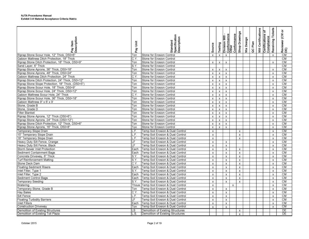
22 shall be returned to the Authority for approval by the Office of the Chief Engineer of the New Jersey Turnpike Authority. Where the Office of the Chief Engineer deems the submitted shop and/or working drawings acceptable, they will be stamped as Approved by an authorized representative of the Chief Engineer using Stamp C as shown in Exhibit 3-8. Approved shop and/or working drawings will then be returned to the CM by the Office of the Chief Engineer for final distribution to the Contractor. Shop and /or working drawings, which are not approved by the Office of the Chief Engineer, will be returned to the DE for further review. The CM will review and approve Contractor submissions in accordance with a Project Specific Materials Acceptance Review Matrix, which will be developed by the DE during Design and provided to the CM for review and acceptance prior to the Pre-Construction meeting for the contract. The CM will also be responsible for review and approval of shop drawings for all items, which are covered by Authority Standard drawings and do not require explicit design on the part of the contractor. All reviewed shop drawings shall be stamped by the CM using Stamp A shown in Exhibit 3-8. A sample matrix of DE and CM responsibilities for review of Contractor Submissions has been prepared as the Materials Acceptance Criteria Matrix (Matrix) as shown in Exhibit 3-9. An electronic spreadsheet version of the Matrix (Exhibit 3-9) will be furnished to the DE by the Authority Project Engineer as part of the Project Design kick-off meeting. This matrix is provided as an example and shall be modified by the DE as appropriate based on specific contract requirements and provided with the Design Phase C submission. This Matrix shall be made available for the scoping and procurement of CM services. A Pre-construction handoff meeting shall be scheduled between the DE and CM to review the design aspects of the project and finalize the Matrix. The Matrix will be updated by the DE and provided to the CM prior to the Pre-Construction meeting for the contract. For the purposes of clarity, the Reviewer shown in the matrix is the party responsible (CM or DE) for review of Contractor submitted materials. Where CM/DE is shown, the Construction Manager shall bear primary responsibility for review of these Contractor submitted materials with assistance and additional review provided by the DE as required for specialty or unusual work features. Where DE/CM is shown, the Design Engineer shall bear primary responsibility for review of these Contractor submitted materials with assistance and additional review provided by the CM as required for features where complex or unusual field performed procedures are to be executed. In any event, where both CM and DE parties are shown in the Reviewer column, both parties shall review the Contractor submitted materials. March
23 Requests for Information During the course of construction, the Resident Engineer may forward to the Engineer a Request for Information (RFI). To prevent costly construction delays, the Engineer shall expeditiously prepare a response to the Resident s question As-Built Plans The preparation of As-built plans shall be the responsibility of the Resident Engineer. The Phase D submission to the Authority s Engineering Department includes the drawings in individual PDF Files with signature and MicroStation Format, which will be forwarded to the Resident. If necessary, the NJTA Engineer shall forward any changes-of-plan in PDF and MicroStation Format that may have occurred during the course of construction to the Resident Engineer. As contracts are ready to be finalized for As-built revisions, the Original Title Sheet Mylar with the Design Engineer and Chief Engineer s signatures and a CD of Electronic Files in PDF and MicroStation Format will be transmitted to the Resident Engineer. This can be picked-up at the Authority s reception desk in the lobby when available. Submission of Final As-built Mylar Drawings and corresponding Electronic Files shall be delivered to Tony Valte, Assistant Project Supervisor with a transmittal containing the following enclosures: 1. One (1) Set of Final As-Built Mylar Drawings sized at 22 X 36 and shall contain the following: a.) Title Sheet must be the Original Title Sheet as provided with the Design Engineer and Chief Engineer s signature. b.) Title Sheet must be dated and Stamped AS-BUILT, signed and dated by the Resident Engineer. The Resident Engineer s Certification Stamp shall state: I CERTIFY THAT TO THE BEST OF MY KNOWLEDGE THIS CONTRACT HAS BEEN CONSTRUCTED IN CONFORMITY WITH THE ORIGINAL PLANS, SPECIFICATIONS AND MODIFICATIONS, AS IDENTIFIED HEREIN AS-BUILT. c.) All other sheets must be stamped AS-BUILT on top of the TITLE BLOCK or REVISION BOX. Note: The text AS-BUILT shall be shown with a bold face font at a one-half inch text height on the Title Sheet above the signatures and above all Title Blocks on all other drawings. d.) The REVISION BOX must have the following information: 1st Column (REV.) shall denote a number inside a triangle to indicate the number of times the sheet was revised. 2nd Column (DESCRIPTION) shall denote either ADDENDUM NO. COP NO. or AS-BUILT 3rd Column (DATE) shall denote date ADDENDUM, COP OR AS-BUILT of sheet completed. March
24 4th Column (BY) shall denote initials of DRAFTER. 5th Column (CHK) shall denote initials of Resident Engineer. 2. One (1) CD of Individual and combined Electronic Files in PDF Version with all required signatures and MicroStation Format. Electronic Files shall contain the same information above. 3. One (1) half-size bound set of As-Built prints and shall contain the same information above Lighting System After the lighting system has been constructed, the Engineer shall perform a verification of the lighting installation, to ensure that the lighting has been installed according to the approved design. This procedure is outlined in Section 7 (Lighting and Power Distribution Systems) of the Design Manual, and will be required before the Authority s Engineering Department issues final acceptance for any lighting system. 3.5 CONSTRUCTABILITY REPORT Purpose and Intent A constructability review shall be performed for specific projects with concurrence of the Chief Engineer. The purpose of this review is to verify that subject projects are safely and logistically constructible using means and methods available to the local contractor community. The intent of the review is not to identify the actual means and methods a contractor will use to construct the project, or to identify all means and methods possible to construct the project. The intent is to identify obstacles before a project is advertised to reduce or prevent delays and unnecessary cost overruns as well as verify that the prepared contract documents are biddable and buildable and that the work described in those documents is theoretically capable of being completed as follows: Within the time provided for each stage and for the overall Contract Using available construction work force, materials, equipment and methods Allowing for the physical space necessary for the work and storage, and available site access Without affecting the safety of the traveling public and without significantly affecting the flow of traffic (i.e. adhering to operational constraints) Without affecting the integrity of the Authority s infrastructure / structures to remain March
25 Respecting external control factors such as environmental / permit restrictions (i.e. in-water work restrictions), seasonal weather, and coordination, with local road, rail, and utility crossings (where present) With due consideration of current or planned projects in the vicinity, as determined by project specific maintenance and protection of traffic (MPT) requirements. For the purposes of the Constructability Report, the limit of consideration is defined in approximate as 3 miles from the outer limits of defined roadway MPT limits visible to the travelling public. This limit may be extended on a project by project basis. The constructability review shall be completed by qualified construction personnel and shall meet qualifications defined in the OPS RFEOI/RFP. The staff performing the constructability review shall not be members of the design team, i.e. they shall be construction supervision personnel or an independent constructability expert. A copy of the Final Constructability Report should be provided to the Construction Manager at the Design to Construction handoff meeting When to Submit the Report The constructability review should be initiated coincident with preparation of the Phase A submission documents, and be advanced as maintenance and protection of traffic is being reviewed. An updated version of the Constructability Report is to be submitted with each phase submission. Comments to the Constructability Report provided by the reviewers are to be addressed with a comment resolution summary document and returned with the phase review comments. Results of the review shall be consolidated in the form of the Constructability Report. The draft Constructability Report shall be submitted no later than four (4) weeks prior to the formal Phase B submission so that the Authority may better compare the documents. It is understood that at the Phase B level of development, estimates of work durations and costs will not be exact. The finalized version of the Report shall be submitted coincident with the Phase D submission package. Depending on the type of work being designed, the Constructability Report will follow the general format below, but will vary on the type of construction proposed. The Design Engineer is advised to consult their Authority Project Engineer for specific format requirements prior to assembling the draft report. It is highly recommended that the Design Engineer submit the proposed table of contents for the report to the Authority Project Engineer prior to proceeding with the draft report General Report Format The following format shall be utilized for the Constructability Report: March
26 Introduction Provide a general description of the work including type, location, milepost limits, total anticipated project construction duration, and milepost-to- milepost limits of traffic lane shifts (taper point to taper point or placement of advance signing, whichever is greater) where present with any potential detours or roadway closures Construction Methods Describe anticipated methods of construction with respect to protecting adjacent traffic, facilities / roadways underneath, size of equipment to be used, temporary works or erection support placement and staging of components to be erected, and anticipated duration and timeframe of construction activities subdivided by construction stage Existing Structure Demolition Describe methods of demolishing major existing structures with respect to protecting adjacent traffic, facilities / roadways underneath, maintaining integrity of structures to remain, size of equipment to be used, behavior changes to the existing structure from partial demolition (if anticipated), placement and staging of both demolition equipment and demolition spoils, and anticipated duration and timeframe of demolition activities subdivided by construction stage Limits of Traffic Effects Where existing traffic must be shifted, show in schematic form the severity of the move as a cross section through the work zone. Also list the limits of the traffic effects, i.e. impacts to entrance / exit ramps and toll plazas, and detours or alternate routes, as the outer limits of the project lane shift taper point mile posts. Also, the availability of lane closings to implement shifts shall be reviewed. The Design Engineer shall review the need for special provisions such as stand-by wrecker service, emergency pull-offs, or special traffic / queue monitoring systems, especially if the length of closing / shift requires such measures and / or the number of lanes are reduced, or shoulders are eliminated during peak travel periods. The Design Engineer shall also verify with their Authority Project Engineer whether other projects (Authority and non-authority) are anticipated to be taking place concurrently to the subject project within the vicinity of the work zones, and where force account work in the Contract is to be provided to allow for emergency maintenance of other structures / infrastructure within the limits of the work zones. March
27 The Design Engineer shall identify the improvements to be addressed by the Contract prior to the traffic shift so flow of traffic in the shifted position is maintained for the stage duration (i.e. installation of additional / new safety features, construction of pavement, reconstruction of existing pavement, pavement repairs, welding of inlet grates, etc.). The Design Engineer shall identify any anticipated detours or High Intensity Construction Cycle (HICC) work as may be required to complete the work or to respect stakeholder limited timeframe accessible work (such as railroads or other facility owners) Specialty Equipment or Water Work Identify specialty construction equipment as it may be required to construct the project, such as large cranes, barge based work, transport equipment for large or heavy prefabricated bridge components, etc. Where long lead times to obtain specialty equipment may be anticipated or if limited use of specialty equipment is required by adjacent facility owners, the Design Engineer shall adjust the project duration as appropriate Construction Staging and Storage Areas Identify lay-down areas for major equipment and components and describe how equipment will access the construction site for supply of labor and materials and for placement of large equipment including temporary construction easements and rights of entry. Need for barges or trestles should be considered for shallow draft water work. Use of schematic representations of the laydown areas and access routes to the construction site is encouraged for the report Approximate Construction Schedule Create a baseline schedule that roughly estimates the order of various construction operations and their durations. The schedule should account for mobilization time for the contractor, winter shut-downs for concrete work, black-out periods for environmental concerns or utility work, any external restrictions such as seasonal traffic, water work limits, stakeholder constraints (railroad closures, navigable channel impacts, etc.) and adjacent roadway project work, lead times for complex or specialty construction items and coordination efforts where long lead times are anticipated such as for local agency approvals or DEP/USCG/ACOE/etc. review periods. March
28 The approximate construction schedule need only be submitted with the draft Constructability Report up to the Phase B submission. For Phase C and Phase D submissions, the overall construction schedule is expected to be submitted as a separate item. March
29 Exhibit 3-5 Design Element Modification Request CONTRACT NO. PHASE DATE DESIGN ELEMENT DESIGN CRITERIA APPROXIMATE COST DESIRABLE MINIMUM PROPOSED DESIRABLE PROPOSED RAMP RADIUS $1,250,000 $250,000 * PROVIDE GENERAL LAYOUT SKETCH(S) OR CORRESPONDENCE AS APPROPRIATE IMPACTS/REASONS: Providing the desirable radius requires the total acquisition of a small commercial property. Reducing the radius eliminates the total acquisition and only requires a slope easement. March
30 Exhibit 3-6 Summary of Permit Requirements CONTRACT NO. PHASE DATE AGENCY TYPE OF PERMIT REASON FOR PERMIT STATUS NJDEP GENERAL WETLANDS BRIDGE PIER IMPACTS TRANSITION AREA PREPARING INITIAL DRAFT FOR REVIEW March
31 Exhibit 3-7 Environmental Permits FEDERAL U.S. Coast Guard (Bridge) USCOE Section 404 (Individual/Nationwide) discharge of fill USCOE Section 10 (Navigable Waters) Section 7 (Endangered Species Consultation) STATE Coastal Area Facility Review Act Hazardous Waste Site Investigation NJDEP Tidal Wetlands NJDEP Waterfront Development NJDEP Tidal Conveyance NJDEP Freshwater Wetlands NJDEP Flood Hazard/Riparian NJDEP Water Quality Certificate OTHERS Delaware Basin Commission Meadowland Commission Pineland Commission Historic Sites Council Green Acres/State House Commission NJ No Net Loss Reforestation Act State Agricultural Development Commission March
32 Exhibit 3-8 Shop and Working Drawings March
33 Exhibit 3-9 Material Acceptance Criteria Matrix March
34
35

36

37
38
39

40

41
42
43

44
45

46

47
48

49

50

51
SECTION 6A ROADWAY PLAN PREPARATION
 SECTION 6A ROADWAY PLAN PREPARATION Table of Contents Page No 6A.1 GENERAL...1 6A.2 PRELIMINARY PLANS...3 6A.2.1 PRELIMINARY PLAN SHEETS...3 6A.2.2 PRELIMINARY PROFILE SHEETS...4 6A.3 PHASE A PLANS...4
Survey Data and TOPO Checklist
 Checklists Survey Data and TOPO Preliminary Plan Field Review Plans o Field Review Erosion Control Right-of-Way and Utility Meeting Plans Final Plan Field Review Plans Methods of Plan Markups Plan-in-Hand
Florida's Turnpike Enterprise Roadway Phase III (90%) & Phase IV (100%) Check List Per FDM and TDH Part 3
 & Phase IV (100%) Check List Per FDM and TDH Part 3") Notes to Reviewers Section 301 Design Exceptions, Variation, and Technical Memorandums Special directives date and source Key Sheet Section 302 Location Map w/ location of project on map All applicable
Notes to Reviewers Section 301 Design Exceptions, Variation, and Technical Memorandums Special directives date and source Key Sheet Section 302 Location Map w/ location of project on map All applicable
SECTION SUBMITTAL PROCEDURES
 SECTION 01330 - SUBMITTAL PROCEDURES PART 1 - GENERAL 1.1 RELATED DOCUMENTS A. Drawings and general provisions of the Contract, including General and Supplementary Conditions and other Division 1 Specification
Maintenance of Traffic sequence of operations including any phasing and detour maps;
 All Local-let projects are required to have a Stage 2 submittal to the LPA Manager for review. The only exceptions are 2-lane resurfacing, striping, guardrail, and raised pavement markers, unless otherwise
SECTION 2 GENERAL REQUIREMENTS
 SECTION 2 GENERAL REQUIREMENTS 2-1 ENGINEER REQUIRED: All plans and specifications for Improvements which are to be accepted for maintenance by the County and private, on-site drainage and grading shall
JEFFERSON LAB TECHNICAL ENGINEERING & DEVELOPMENT FACILITY (TEDF ONE) Newport News, Virginia
 Newport News, Virginia") BULLETIN NO. 6 TO THE PLANS AND SPECIFICATIONS FOR JEFFERSON LAB TECHNICAL ENGINEERING & DEVELOPMENT FACILITY (TEDF ONE) Newport News, Virginia EwingCole Architects.Engineers.Interior Designers.Planners
BULLETIN NO. 6 TO THE PLANS AND SPECIFICATIONS FOR JEFFERSON LAB TECHNICAL ENGINEERING & DEVELOPMENT FACILITY (TEDF ONE) Newport News, Virginia EwingCole Architects.Engineers.Interior Designers.Planners
CITY OF LOMPOC DEVELOPMENT ASSISTANCE BROCHURE ENCROACHMENT PERMITS AND PUBLIC IMPROVEMENT PLANS
 CITY OF LOMPOC DEVELOPMENT ASSISTANCE BROCHURE E-10 ENCROACHMENT PERMITS AND PUBLIC IMPROVEMENT PLANS The City of Lompoc has determined that the Engineering Division should administer and issue Encroachment
Working Drawing Manual
 Working Drawing Manual 2012 Table of Contents Section 1 Working Drawing Types... 1 1.1 General... 1 Section 2 Processing Steps... 1 2.1 Project Manager... 1 2.2 Engineering Document Unit... 2 2.3 Contractor...
List of Figures. List of Forms
 City of Columbia Engineering Regulations PART 1: SUBMISSION OF PLANS Table of Contents Paragraph Description Page No. 1.1 General 1-1 1.2 Engineer s Report 1-1 1.3 Plans 1-3 1.4 Revisions to Approved Plan
TABLE OF CONTENTS 1200 PLAN PREPARATION
 1200 PLAN PREPARATION TABLE OF CONTENTS PAGE 1201 General Plan Sheet Information... 12-1 1201.1 Introduction... 12-1 1201.2 Unit of Measure... 12-1 1201.3 Plan Sheet Materials and File Format... 12-1 1201.4
MISSISSIPPI STATE UNIVERSITY Office of Planning Design and Construction Administration
 SECTION 01 340 - SHOP DRAWINGS, PRODUCT DATA AND SAMPLES PART 1 - GENERAL 1.1 RELATED DOCUMENTS A. Drawings and general provisions of the Contract, including General and Supplementary Conditions and other
PROCEDURE FOR PROCESSING WORKING DRAWINGS
 PROCEDURE FOR PROCESSING WORKING DRAWINGS MAY 2005 Procedure for Processing Working Drawings GENERAL: The procedure for the review and processing of working drawings provide for two primary types of drawings,
SITE PLAN Application Packet (Required For All Non-Residential Development Projects)
") SITE PLAN Application Packet (Required For All Non-Residential Development Projects) Community Development Department 90 North Main Street, Tooele, UT 84074 (435) 843-2130 Fax (435) 843-2139 Dear Applicant,
SITE PLAN Application Packet (Required For All Non-Residential Development Projects) Community Development Department 90 North Main Street, Tooele, UT 84074 (435) 843-2130 Fax (435) 843-2139 Dear Applicant,
A. This section specifies procedural requirements for Shop Drawings, product data, samples, and other miscellaneous Work-related submittals.
 SECTION 01300 PART 1 GENERAL 1.1 SECTION INCLUDES A. Description of Requirements B. Submittal Procedures C. Specific Submittal Requirements D. Action on Submittals E. Repetitive Review 1.2 DESCRIPTION
UNION COUNTY VOCATIONAL-TECHNICAL SCHOOLS West Hall Addition Project Raritan Road, Scotch Plains, NJ
 SECTION 013300 - SUBMITTAL PROCEDURES PART 1 - GENERAL 1.1 RELATED DOCUMENTS A. Drawings and general provisions of the Contract, including General and Supplementary Conditions and other Division 1 General
Update: July 20, 2012
 Location and Design Manual, Volume 3 ODOT Office of CADD and Mapping Services Update: July 20, 2012 ** NOTE: All metric references have been removed from this manual. ** PREFACE REVISIONS Glossary of Terms
SECTION SUBMITTAL PROCEDURES
 SECTION 013300 PART 1 - GENERAL 1.1 RELATED DOCUMENTS A. Drawings and general provisions of the Contract, including General and Supplementary Conditions and other Division 01 Specification Sections, apply
Working Drawing Procedure
 Working Drawing Procedure June 2007 Prepared by Structural Engineering & Construction Services 1.0 Working Drawing Procedure 1.1 General There are two primary types of working drawings, those requiring
A. Action Submittals: Written and graphic information that requires Architect's responsive action.
 SECTION 01330 - SUBMITTAL PROCEDURES PART 1 - GENERAL 1.1 RELATED DOCUMENTS A. Drawings and general provisions of the Contract, including General and Supplementary Conditions and other Division 1 Specification
TCC/SHORE TRANSIT BUS MAINTENANCE FACILITY - PHASE II
 SECTION 013300 - SUBMITTAL PROCEDURES PART 1 - GENERAL 1.1 RELATED DOCUMENTS A. Drawings and general provisions of the Contract, including General and Supplementary Conditions and other Division 01 Specification
Washington County Road Engineering Plan Submittal/Review Checklist
 Washington County Road Engineering Plan Submittal/Review Checklist Washington County Land Use Case File Number: Parcel(s): Developer/Owner Name(s): Developer/Owner E-mail(s): The following elements should
SANITARY SEWER SYSTEM ADMINISTRATIVE STANDARDS A.1 SANITARY SEWER SYSTEM PLAN SUBMITTAL PROCEDURES AND GENERAL REQUIREMENTS
 SANITARY SEWER SYSTEM ADMINISTRATIVE STANDARDS A.1 SANITARY SEWER SYSTEM PLAN SUBMITTAL PROCEDURES AND GENERAL REQUIREMENTS All plans for sanitary sewer main extensions, improvements and modifications
East Central College
 SECTION 013300 - SUBMITTAL PROCEDURES PART 1 - GENERAL 1.1 RELATED DOCUMENTS A. Drawings and general provisions of the Contract, including General and Supplementary Conditions and other Division 01 Specification
PRELIMINARY PLAT CHECK LIST
 Name of Proposed Subdivision: The following items must be included with the initial submittal of a Preliminary Plat: Application, filled out completely Project Narrative Pre-application Conference Report
Site Plan Review Application. Interest in the Property (e.g. fee simple, land option, etc.)
") 1. Identification CITY OF FENTON 301 South Leroy Street Fenton, Michigan 48430-2196 (810) 629-2261 FAX (810) 629-2004 Site Plan Review Application Project Name Applicant Name Address City/State/Zip Phone
1. Identification CITY OF FENTON 301 South Leroy Street Fenton, Michigan 48430-2196 (810) 629-2261 FAX (810) 629-2004 Site Plan Review Application Project Name Applicant Name Address City/State/Zip Phone
CITY OF LA MARQUE CHAPTER GRAPHIC REQUIREMENTS CONSTRUCTION PLAN AND MISCELLANEOUS REQUIREMENTS
 CITY OF LA MARQUE CHAPTER 2 -------------------------------------------- GRAPHIC REQUIREMENTS CONSTRUCTION PLAN AND MISCELLANEOUS REQUIREMENTS CHAPTER 2 ------------------------------------------------
B.2 MAJOR SUBDIVISION PRELIMINARY PLAN CHECKLIST
 B.2 MAJOR SUBDIVISION PRELIMINARY PLAN CHECKLIST YES* GENERAL SUBMISSION ITEMS Does the submission include: 1. Thirteen (13) copies of completed Application Form? 2. Thirteen (13) copies of the Preliminary
DIVISION 1 - GENERAL REQUIREMENTS SECTION SUBMITTALS
 DIVISION 1 - GENERAL REQUIREMENTS SECTION 01300 - SUBMITTALS PART 1 - GENERAL 1.1 STIPULATIONS A. The section "Special Requirements" forms a part of this section by this reference thereto and shall have
UCCS University Hall Fire Sprinkler System Upgrade March 1, 2011 RTA SECTION SUBMITTAL PROCEDURES PART 1 - GENERAL
 SECTION 013300 - SUBMITTAL PROCEDURES PART 1 - GENERAL 1.1 RELATED DOCUMENTS A. Drawings and general provisions of the Contract, including General and Supplementary Conditions and other Division 01 Specification
SECTION SUBMITTAL PROCEDURES PART 1 - GENERAL 1.1 RELATED DOCUMENTS
 SECTION 01 33 00 - SUBMITTAL PROCEDURES PART 1 - GENERAL 1.1 RELATED DOCUMENTS A. Drawings and general provisions of the Contract, including General and Supplementary Conditions and other Division 01 Specification
A. Action Submittals: Written and graphic information that requires Engineer's responsive action.
 SECTION 01330 - SUBMITTAL PROCEDURES PART 1 - GENERAL 1.1 RELATED DOCUMENTS A. Drawings and general provisions of the Contract, including General and Supplementary Conditions and other Division 1 Specification
NORTHWESTERN UNIVERSITY PROJECT NAME JOB # ISSUED: 03/29/2017
 SECTION 01 3300 - SUBMITTAL PROCEDURES PART 1 - GENERAL 1.1 RELATED DOCUMENTS A. Drawings and general provisions of the Contract, including General and Supplementary Conditions and other Division 01 Specification
SECTION ADMINISTRATIVE REQUIREMENTS SECTION ADMINISTRATIVE REQUIREMENTS
 PART 1 GENERAL 1.01 SECTION INCLUDES A. Project Coordination. B. Preconstruction meeting. C. Progress meetings. D. Preinstallation conferences. E. Requests for information (RFI). F. Coordination drawings.
City of Massillon Site Plan Checklist
 City of Massillon Site Plan Checklist The following information MUST be included with all Site Plans submitted for review and processing in order to constitute a complete Site Plan Package. Incomplete
CHAPTER 14: TRAFFIC SIGNAL STANDARDS Introduction and Goals Administration Standards Standard Attachments 14.
 14.00 Introduction and Goals 14.01 Administration 14.02 Standards 14.03 Standard Attachments 14.1 14.00 INTRODUCTION AND GOALS The purpose of this chapter is to outline the City s review process for traffic
TOWN OF AMHERST PLANNING DEPARTMENT MINOR SITE PLAN AND MINOR ADJUSTMENT REVIEW AND APPROVAL PROCEDURE
 TOWN OF AMHERST PLANNING DEPARTMENT MINOR SITE PLAN AND MINOR ADJUSTMENT REVIEW AND APPROVAL PROCEDURE This application package includes the following: Application Procedures Application Form & Checklist
SECTION SUBMITTALS. A. PART A and DIVISION 1 of PART B are hereby made a part of this SECTION.
 SECTION 013300 PART 1 GENERAL 1.01 GENERAL REQUIREMENTS A. PART A and DIVISION 1 of PART B are hereby made a part of this SECTION. B. Examine all conditions as they exist at the project prior to submitting
Answer: Qualification statement should be provided with the bid.
 Little Diversified Architectural Consulting, Inc. 5815 Westpark Drive Charlotte, North Carolina 28217 Phone: 704-525-6350 Fax: 704-561-8700 Lincoln County Probation Renovation 208 N. Government Street
CHECKLIST PRELIMINARY SUBDIVISION AND PRELIMINARY SITE PLAN
 N/A Waiver (1) Four (4) copies of application form. (2) Fifteen (15) copies of plan (3) Subdivision/site plan application fee & professional review escrow deposit (4) Variance application fee & professional
CHAPTER 2 SUBMITTAL AND REVIEW PROCEDURES TABLE OF CONTENTS
 CHAPTER 2 SUBMITTAL AND REVIEW PROCEDURES TABLE OF CONTENTS Section Title Page 2.1 General... 2-1 2.1.1 General Submittal Criteria and Procedures...2-1 2.1.2 Authorization/Certification...2-1 A. Designer
SECTION CONTRACTOR SUBMITTALS. A. All submittals by the CONTRACTOR shall be submitted to the ENGINEER.
 SECTION 01300 - PART 1 - GENERAL 1.1 GENERAL A. All submittals by the CONTRACTOR shall be submitted to the ENGINEER. B. Unless otherwise noted, within 14 days after the date of commencement as stated in
CITY OF BEVERLY HILLS Department of Public Works and Transportation Civil Engineering Division SANITARY SEWER IMPROVEMENT PLAN REVIEW CHECKLIST
 CITY OF BEVERLY HILLS Department of Public Works and Transportation Civil ing Division SANITARY SEWER IMPROVEMENT PLAN REVIEW CHECKLIST The following checklist consists of the minimum requirements for
CHAPTER 11 PRELIMINARY SITE PLAN APPROVAL PROCESS
 CHAPTER 11 PRELIMINARY SITE PLAN APPROVAL PROCESS 11.01.00 Preliminary Site Plan Approval 11.01.01 Intent and Purpose 11.01.02 Review 11.01.03 Application 11.01.04 Development Site to be Unified 11.01.05
SECTION SHOP DRAWINGS, PRODUCT DATA, AND SAMPLES
 SECTION 01334 SHOP DRAWINGS, PRODUCT DATA, AND SAMPLES PART 1 GENERAL 1.01 SUMMARY A. Submit to the ENGINEER for review, such working drawings, shop drawings, test reports and data on materials and equipment
APPLICATION FOR SITE PREPARATION PERMIT
 Engineering Division 550 Landa Street New Braunfels, Texas 78130 (830) 221-4020 1. Subdivision/Plat Name: Location Description/ Nearest Intersection: Acreage: APPLICATION FOR SITE PREPARATION PERMIT No.
CITY OF BEVERLY HILLS Department of Public Works and Transportation Civil Engineering Division STREET/ALLEY IMPROVEMENT PLAN REVIEW CHECKLIST
 CITY OF BEVERLY HILLS Department of Public Works and Transportation Civil ing Division STREET/ALLEY IMPROVEMENT PLAN REVIEW CHECKLIST The following checklist consists of the minimum requirements for preparation
Plan Preparation Checklist
 Appendix D Plan Preparation Checklist It is the responsibility of the Designer to complete and submit this checklist along with all required drawings for OUC (EFP) Review. All drawings submitted for OUC
Porter County Plan Commission
 Plan Type: Development Plan Administrative DRC PC Primary Plan Administrative DRC PC Secondary Plat/Replat Administrative DRC PC PUD Conceptual Detailed Final Project Information Project Name: Developer
City of Beaumont. Public Works Engineering. Street Improvement Plan Checklist REV 4/18/16
 City of Beaumont Public Works Engineering Project Name: TR: Project No.: Date: Street Improvement Plan Checklist Chk A. All Sheets 1. 24" x 36" 2. Signed by the engineer-of-work 3. Marked with the contact
CITY OF BEVERLY HILLS Department of Public Works and Transportation Civil Engineering Division STORM DRAIN IMPROVEMENT PLAN REVIEW CHECKLIST
 CITY OF BEVERLY HILLS Department of Public Works and Transportation Civil ing Division STORM DRAIN IMPROVEMENT PLAN REVIEW CHECKLIST The following checklist consists of the minimum requirements for preparation
Section Meetings Section Material and Equipment. None Required
 January 2000 Page 1 of 8 PART 1 GENERAL 1.01 OTHER CONTRACT DOCUMENTS 1.02 DESCRIPTION OF WORK 1.03 RELATED WORK PART 2 PRODUCTS The General Conditions of the Contract, General Requirements and Supplemental
SECTION 9.00 AS-BUILT DRAWING REQUIREMENTS SUB-INDEX
 SECTION 9.00 AS-BUILT DRAWING REQUIREMENTS SUB-INDEX 9.00 AS-BUILT DRAWING REQUIREMENTS 9.01 As-Built Check List 1 Supp 1 2016 Supp # 2 Aug. 2017 AS-BUILT DRAWING REQUIREMENTS As-Built Review Fee is $200.00
SECTION 3 IMPROVEMENT PLAN REQUIREMENTS
 SECTION 3 IMPROVEMENT PLAN REQUIREMENTS CONTENTS Page 3-1 Digital Submittals 3-2 3-2 Paper Size and Scale 3-2 3-3 Drafting Standard 3-2 3-4 Title Sheet 3-2 3-5 Title Block 3-3 3-6 Drainage, Sewer, Water,
MnDOT Contract Exhibit A - Scope of Services
 Introduction Information Introduction This Scope of Services represents work on two individual highway improvement projects as described below. The State intends to let two of the projects as separate
State College Area School District
 State College Area School District The following is a guideline for project design submittals to the Facility Committee of the State College Area School District. During the design process the committee
Mailing Address: Fax number: City: State: Zip: Property Owner: City: State: Zip: City: State: Zip:
 / Department of Community Development ARCHITECTURAL REVIEW APPLICATION 73-510 Fred Waring Drive Palm Desert California 92260 (760) 346-0611 Fax (760) 776-6417 Applicant: Telephone: Mailing Address: Fax
SECTION ADMINISTRATIVE REQUIREMENTS
 PART 1 GENERAL 1.01 SECTION INCLUDES A. Electronic document submittal service. B. Preconstruction meeting. C. Progress meetings. D. Construction progress schedule. E. Coordination drawings. SECTION 013000
Detail Design For Pavement Rehabilitation on Trunk Highway 14 From Tracy to Revere
 Detail Design For Pavement Rehabilitation on Trunk Highway 14 From Tracy to Revere Section 1 Introduction and Intersection Information State Project (SP) 6401-37 on MN Highway 14 SP 6401-37 is a Bituminous
LARAMIE COUNTY PLANNING & DEVELOPMENT OFFICE 3966 Archer Pkwy Cheyenne, WY Phone (307) Fax (307)
 Fax (307)") 3966 Archer Pkwy Cheyenne, WY 82009 planning@laramiecounty.com Phone (307) 633-4303 Fax (307) 633-4616 SITE PLAN REVIEW PROCESS 1. Pre-Application Meeting: The applicant shall meet with a Laramie County
3966 Archer Pkwy Cheyenne, WY 82009 planning@laramiecounty.com Phone (307) 633-4303 Fax (307) 633-4616 SITE PLAN REVIEW PROCESS 1. Pre-Application Meeting: The applicant shall meet with a Laramie County
SECTION SUBMITTALS PART 1 - GENERAL 1.01 RELATED DOCUMENTS
 SECTION 01300 SUBMITTALS PART 1 - GENERAL 1.01 RELATED DOCUMENTS A. Drawings and general provisions of Contract, including General and Supplementary Conditions and other Division-1 Specification Sections,
CHAPTER 3 INFORMATION REQUIRED FOR PUBLIC IMPROVEMENT CONSTRUCTION PLANS TABLE OF CONTENTS
 CHAPTER 3 INFORMATION REQUIRED FOR PUBLIC IMPROVEMENT CONSTRUCTION PLANS TABLE OF CONTENTS Section Title Page 3.1 General... 3-1 3.1.1 Plan Set...3-1 A. Loveland (City Limits Only)...3-1 3.1.2 Final Mylars...3-1
Grading, Erosion and Sediment Control (GESC) Checklist
 Checklist") Development Services Department 100 N. Wilcox Street, Castle Rock CO 80104 Planner of the Day 303-660-1393 Grading, Erosion and Sediment Control (GESC) Checklist A complete Grading, Erosion and Sediment
Development Services Department 100 N. Wilcox Street, Castle Rock CO 80104 Planner of the Day 303-660-1393 Grading, Erosion and Sediment Control (GESC) Checklist A complete Grading, Erosion and Sediment
CHAPTER 2C - PRELIMINARY DESIGN. General... 2C-1. Review of Work Load... 2C-2 Establishing Priorities... 2C-2
 SECTION 2C - 1 - PROJECT REVIEW CHAPTER 2C - PRELIMINARY DESIGN General... 2C-1 SECTION 2C - 2 - COORDINATING TIME SCHEDULES Review of Work Load... 2C-2 Establishing Priorities... 2C-2 SECTION 2C 3 - REVIEW
City of Colleyville Community Development Department. Site/Landscape Plan Application Packet
 City of Colleyville Community Development Department Site/Landscape Plan Application Packet 1 Development Application Fees City of Colleyville 100 Main Street Colleyville TX 76034 817.503.1050 Zoning Zoning
HAMILTON TOWNSHIP Department of Planning and Zoning Application for a Commercial / Industrial Site Plan Review
 HAMILTON TOWNSHIP Department of Planning and Zoning Application for a Commercial / Industrial Site Plan Review Date: Application is hereby made for a Site Plan Review for a commercial or industrial use.
SECTION A. RFI: Request from Contractor seeking interpretation, information, or clarification of the Contract Documents.
 SECTION 01 3000 PART 1 GENERAL 1.1 SECTION INCLUDES A. Electronic document submittal service. B. Preconstruction meeting. C. Submittals for review, information, and project closeout. D. Submittal procedures.
MnDOT Contract Exhibit A- Scope of Services. Project Information -
 Detail Design For Pedestrian Improvements on Trunk Highways 23, 59, and 68 In the Marshall Area Introduction and Project Information Introduction The purpose of this contract is to provide the State with
VARIANCE APPLICATION (NO SITE PLAN OR SUBDIVISION)
") VARIANCE APPLICATION (NO SITE PLAN OR SUBDIVISION) 190-66. General procedure for completeness review. A. In order to be determined complete for review by the Board, all of the required information must
VARIANCE APPLICATION (NO SITE PLAN OR SUBDIVISION) 190-66. General procedure for completeness review. A. In order to be determined complete for review by the Board, all of the required information must
This specification describes the general requirements for Engineering Services provided to Vale.
 1/9 1.0 PURPOSE This specification describes the general requirements for Engineering Services provided to Vale. 2.0 GENERAL For the purposes of this document, the Engineering Consultant shall be referred
SECTION SHOP DRAWINGS, PRODUCT DATA, AND SAMPLES
 SECTION 01 33 23 SHOP DRAWINGS, PRODUCT DATA, AND SAMPLES PART 1 GENERAL 1.1 DESCRIPTION A. This specification defines the general requirements and procedures for submittals. A submittal is information
Ohio Department of Transportation Division of Production Management Office of Geotechnical Engineering. Geotechnical Bulletin
 Ohio Department of Transportation Division of Production Management Office of Geotechnical Engineering Geotechnical Bulletin GB 5 GEOTECHNICAL SUBMISSION GUIDELINES Geotechnical Bulletin GB5 was developed
Chapter 1 General Design Information
 Chapter 1 General Information Introduction The primary aim in both designing and checking is to produce a structure that will safely carry the anticipated loads. The design team, consisting of the designers,
CHAPTER 10 MICHIGAN DESIGN MANUAL BRIDGE DESIGN (SI) SHOP DRAWING REVIEW TYPES OF SHOP DRAWINGS Structural Steel
 SHOP DRAWING REVIEW TYPES OF SHOP DRAWINGS Structural Steel") CHAPTER 10 SHOP DRAWING REVIEW 10.01 TYPES OF SHOP DRAWINGS 10.01.01 Structural Steel 10.01.02 Prestressed Concrete 10.01.03 Bearings 10.01.04 Metal Stay - In - Place Forms () 10.01.05 Expansion Joints
CHAPTER 10 SHOP DRAWING REVIEW 10.01 TYPES OF SHOP DRAWINGS 10.01.01 Structural Steel 10.01.02 Prestressed Concrete 10.01.03 Bearings 10.01.04 Metal Stay - In - Place Forms () 10.01.05 Expansion Joints
Site Plan/Building Permit Review
 Part 6 Site Plan/Building Permit Review 1.6.01 When Site Plan Review Applies 1.6.02 Optional Pre- Application Site Plan/Building Permit Review (hereafter referred to as Site Plan Review) shall be required
Exhibit A SCOPE OF WORK AND DELIVERABLES T.H. 169 Mountain Iron to Hoover Road in Virginia
 Exhibit A SCOPE OF WORK AND DELIVERABLES T.H. 169 Mountain Iron to Hoover Road in Virginia PROJECT OVERVIEW S.P. 6935-89 is on T.H. 169 from 0.07 miles west of CR 109 in Mt. Iron to Hoover Road in Virginia
DIVISION 1 GENERAL REQUIREMENTS SECTION SUBMITTAL PROCEDURES
 DIVISION 1 GENERAL REQUIREMENTS SECTION 01 33 00 PART 1 - GENERAL 1.1 SUMMARY A. This section includes administrative and procedural requirements for submittals required for performance of the work, including
RESIDENTIAL DEMOLITION PERMIT APPLICANT CHECKLIST
 RESIDENTIAL DEMOLITION PERMIT APPLICANT CHECKLIST The purpose of this form is to inform applicants of: 1) the requirements for building permits and stormwater permits for residential demolition projects;
Minor Site Plan Application and Checklist Land Disturbing Activities
 Minor Site Plan Application and Checklist Land Disturbing Activities INSTRUCTIONS: Please provide the requested information below. The Development Services Department reviews each site plan submittal based
APPENDIX K DEPARTMENT OF PLANNING AND CODE ENFORCEMENT SUBDIVISION APPLICATION CENTER SUBMITTAL CHECKLIST
 VI-K -1 of 8 APPENDIX K DEPARTMENT OF PLANNING AND CODE ENFORCEMENT SUBDIVISION APPLICATION CENTER SUBMITTAL CHECKLIST Final Submittal Major Subdivision Project Name Subdivision Number Location (Street
LOWNDES COUNTY ENGINEERING PLAN REVIEW CHECKLIST. Design Professional: Phone: Developer: Phone: 2 nd Submittal (No Fee)
") MEMORANDUM MICHAEL B. FLETCHER, P.E. COUNTY ENGINEER 327 N. Ashley Street Valdosta, GA 31601 Telephone: (229) 671-2424 Fax: (229) 245-5299 mfletcher@lowndescounty.com LOWNDES COUNTY ENGINEERING PLAN REVIEW
MEMORANDUM MICHAEL B. FLETCHER, P.E. COUNTY ENGINEER 327 N. Ashley Street Valdosta, GA 31601 Telephone: (229) 671-2424 Fax: (229) 245-5299 mfletcher@lowndescounty.com LOWNDES COUNTY ENGINEERING PLAN REVIEW
580 - NOISE BARRIERS OPSS 580 INDEX
 580 - OPSS 580 INDEX 580.1 GENERAL 580.1.1 Noise Barrier Design Elements 580.1.1.1 Wind-Load Designs 580.1.1.2 Sound-Absorptive Barriers 580.1.1.3 Noise Barrier Colour, Pattern and Texture 580.1.2 Grading
3. The PAC (Permit Application Center) will notify the design professional of plan review results.
 will notify the design professional of plan review results.") Planning and Development Dept. Infrastructure Division P.O. Box 11706, or 155 Johnston Street Rock Hill, South Carolina 29731-1706 Phone: 803-329-5515 FAX: 803-329-7228 www.cityofrockhill.com AS-BUILT
Planning and Development Dept. Infrastructure Division P.O. Box 11706, or 155 Johnston Street Rock Hill, South Carolina 29731-1706 Phone: 803-329-5515 FAX: 803-329-7228 www.cityofrockhill.com AS-BUILT
Conceptual, Preliminary and Final Site Plan Review in Holladay City
 Conceptual, Preliminary and Final Site Plan Review in Holladay City The City of Holladay incorporated in December, 1999 and adopted its own zoning ordinance in May, 2000. All land use decisions are made
FREMONT COUNTY. APPLICATION FOR ZONE CHANGE #2 USE DESIGNATION PLAN (Requires Subsequent Approval of ZC #2 Final Designation Plan) 1.
 1.") FREMONT COUNTY APPLICATION FOR ZONE CHANGE #2 USE DESIGNATION PLAN (Requires Subsequent Approval of ZC #2 Final Designation Plan) 1. Project Name: 2. Applicant: Address: City: State: Zip Code: Telephone
FREMONT COUNTY APPLICATION FOR ZONE CHANGE #2 USE DESIGNATION PLAN (Requires Subsequent Approval of ZC #2 Final Designation Plan) 1. Project Name: 2. Applicant: Address: City: State: Zip Code: Telephone
Minor Site Plan Review Process
 Minor Site Plan Review Process Pre-Application Conference Community Meeting (optional) Submit Application Determination of Completeness Staff Report (optional) Technical Review Committee Decision Notice
SECTION SUBMITTAL PROCEDURES
 SECTION 01330 SUBMITTAL PROCEDURES PART 1 - GENERAL 1.1 DESCRIPTION A. Scope: 1. CONTRACTOR shall provide submittals in accordance with the General Conditions as modified by the Supplementary Conditions,
SECTION PROJECT MANAGEMENT AND COORDINATION
 SECTION 013100 - PROJECT MANAGEMENT AND COORDINATION PART 1 - GENERAL 1.1 RELATED DOCUMENTS A. Drawings and general provisions of the Contract, including General and Supplementary Conditions and other
.2 Accompany all submissions with a transmittal letter, in duplicate, containing:.4 Specification Section number for each submittal
 City of Winnipeg Brady Road Landfill Site Section 01300 New Entrance and Scale Facility Page 1 of 4 SUBMITTALS 1. SHOP DRAWINGS 1.1 General.1 Arrange for the preparation of clearly identified Shop Drawings
Taylor County July 2011 SECTION SHOP DRAWINGS, WORKING DRAWINGS AND SAMPLES
 SECTION 01340 SHOP DRAWINGS, WORKING DRAWINGS AND SAMPLES PART 1 - GENERAL 1.1 REQUIREMENTS INCLUDED A. Contractor shall submit to the Architect/Engineer for review and exception, if any, such working
Exhibit A Scope of Services and Deliverables West Swan River Bridge Approaches
 Exhibit A Scope of Services and Deliverables West Swan River Bridge Approaches PROJECT OVERVIEW S.P. 6929-21 is on T.H. 73 in St. Louis County. The project includes replacement of existing Bridge #9262
SPECIAL PROVISION Description of Project, Scope of Contract and Sequence of Work
 2004 Specifications CSJ 0110-04-166 SPECIAL PROVISION 000--363 Description of Project, Scope of Contract and Sequence of Work 1. General. The work to be performed on this project consists of furnishing,
September 6, 2018 CITY OF BERKELEY SHATTUCK RECONFIGURATION AND PEDESTRIAN SAFETY PROJECT SPECIFICATION NO C ADDENDUM NO.
 Department of Public Works Transportation Division September 6, 2018 CITY OF BERKELEY SHATTUCK RECONFIGURATION AND PEDESTRIAN SAFETY PROJECT SPECIFICATION NO. 17-11090-C ADDENDUM NO. 3 Dear Bidder: The
SECTION SCHEDULE OF VALUES PART 1 - GENERAL 1.1 THE REQUIREMENT A. This Section defines the process whereby the Schedule of Values (Lump Sum
 SECTION 013201 - SCHEDULE OF VALUES PART 1 - GENERAL 1.1 THE REQUIREMENT A. This Section defines the process whereby the Schedule of Values (Lump Sum Pay Unit price breakdown) shall be developed and ultimately
TAB B-9 RECORD DRAWINGS
 TAB B-9 RECORD DRAWINGS Project record drawings and shall be prepared for all University of Arizona projects. The concept Record Drawings shall replace what has previously been called As-Builts. During
APPLICATION FOR CERTIFICATE OF APPROPRIATENESS IN THE HISTORIC DESIGN REVIEW DISTRICT
 209 South Main Street Marysville, Ohio 43040 Phone: (937) 645-7350 Fax: (937) 645-7351 www.marysvilleohio.org APPLICATION FOR CERTIFICATE OF APPROPRIATENESS IN THE HISTORIC DESIGN REVIEW DISTRICT *** IMPORTANT
SUBMITTAL REQUIREMENTS FOR USE PROCESS III OR PROCESS IV
 COMMUNITY DEVELOPMENT DEPARTMENT 33325 8 th Avenue South Federal Way WA 98003 253-835-2607; Fax 253-835-2609 www.cityoffederalway.com SUBMITTAL REQUIREMENTS FOR USE PROCESS III OR PROCESS IV USE PROCESS
DIGITAL DATA SUBMISSION STANDARDS Procedures and Guidelines
 DIGITAL DATA SUBMISSION STANDARDS Procedures and Guidelines 2014 Citizens Wastewater of Westfield - GIS Digital Standards Table of Contents Introduction... 3 Definitions and Terms... 3 Reference Documents...
DEVELOPMENT REVIEW COMMENTS LAND DISTURBANCE PERMIT (LDP) CLEARING CLEARING & GRUBBING GRADING. Date Reviewed by. Project Name
 CLEARING CLEARING & GRUBBING GRADING. Date Reviewed by. Project Name") GWINNETT COUNTY Department of Planning and Development One Justice Square 446 West Crogan Street Suite 150 1 st Floor Lawrenceville, GA 30046 Phone: 678.518.6000 Fax: 678.518.6240 www.gwinnettcounty.com
GWINNETT COUNTY Department of Planning and Development One Justice Square 446 West Crogan Street Suite 150 1 st Floor Lawrenceville, GA 30046 Phone: 678.518.6000 Fax: 678.518.6240 www.gwinnettcounty.com
Guidelines for the Preparation of Traffic Signal & Intelligent Transportation System Plans on Design-Build Projects August 2007
 Guidelines for the Preparation of Traffic Signal & Intelligent Transportation System Plans on Design-Build Projects August 2007 INTRODUCTION Use the following Guidelines in conjunction with the Traffic