ENGINEERING SURVEYING (221 BE) Setting Out And Site Control. Sr Tan Liat Choon Mobile:
|
|
|
- Mervin Campbell
- 6 years ago
- Views:
Transcription


1 ENGINEERING SURVEYING (221 BE) Setting Out And Site Control Sr Tan Liat Choon Mobile:
2 WHAT IS SETTING OUT Setting out is all about transferring measurements from working drawings to the building plot Setting out is simply the physical transfer into the ground what was initially on plan or in paperwork. Transferring the building professionals drawing (the architect) plan onto the ground is a process of setting out Plan or drawing where a projected building is drawn and numeric values of setting out elements are written Pegs and profiles are set out to mark the positions of corners, walls and foundations. Most working drawings show separate measurements for individual features such as walls, windows and doors For setting out, it is useful to turn these separate measurements into running dimensions. To do this, each measurement along the plan is added to the ones before it 2
3 SETTING OUT OF BUILDING Undertaken once the site has been cleared of any details and any reduced level excavation work is finished Accurate setting out is of principal importance and should therefore only be carried out by competent person and all their work thoroughly checked The first task in setting out the building is to establish a base line to which all the setting out can be related Marking of a building position, size and shape in terrain A temporary bench mark is a fix point on site to which all levels related and should be established at an early stage 3
4 SETTING OUT OF BUILDING Frame buildings are usually related to a grid The intersections of the grid lines being the centre point of an isolated or pad foundation The grid is established using a total station and marking the grid line intersections with pegs One the grid has been set out, offset pegs or profiles can be fixed clear of any subsequent excavation work The overall outline of the reduced level area can be set out using a total station, ranging rods, tape and pegs working from a base line To control the depth of excavation, sight rails are set up at a convenient height and at positions which will enable a traveller to be used 4


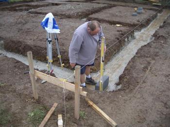
5 SETTING OUT OF BUILDING 5
6 SETTING OUT OF BUILDING A block plan will show where a building will be positioned on site and the shape and size of the building on plan. Measurements are marked on the plan to show distances of the building from the boundaries or other fixed points and the measurements of the building itself. These are used when setting out the perimeter wall To mark out the site wooden pegs are driven into the ground at corners. Nails are fixed on the tops of the pegs and a builder s line pulled taut from nail to nail to show the position of the wall 6

7 SETTING OUT OF BUILDING The tops of the pegs must be level for accurate measurements to be obtained. This is achieved by making the first peg (usually on the front line of the building) a datum peg. It is from this peg that all the other pegs are levelled. Levelling is done by putting a straight-edge and spirit level across two pegs and hammering the second peg down until the bubble in the spirit level is level 7
8 SETTING OUT OF BUILDING Distances between corners are often more than the length of the straight-edge and so temporary, intermediate pegs are used to transfer the level across to the next corner. Reverse the spirit level to check if it is accurate 8
9 SETTING OUT OF BUILDING Pegs are often positioned beyond corners so that the line crosses at the exact corner 9
10 SETTING OUT OF BUILDING Right angles: Most buildings are based on squares or rectangles. This means that corners will be right angles 90º. To make sure that lines are at right angles to each other, corners can be set out using the 3:4:5 method. This will always give a perfect right angle of measurement accurately 10
11 SETTING OUT OF BUILDING Checking for square: An easy way of checking if a square or rectangle has been set out correctly, with all corners at 90º, is to check the diagonals across corners. If they are exactly the same length the setting out is correct 11
12 SETTING OUT OF BUILDING Horizontal lines: Horizontal lines are needed when carrying out most construction skills, e.g. courses of brickwork, wall tiles, work tops etc. A spirit level, sometimes with a straight-edge, is used to obtain the true level The bubble should be between the two lines on the glass tube of the level when it is perfectly flat. The accuracy of the level can be checked, by turning it end to end, to see that the bubble is still between the lines. If not, the level itself needs adjusting 12

13 SETTING OUT OF BUILDING Vertical lines: Vertical lines are needed for most construction activities, e.g. corners of brickwork, vertical lines of wall tiles, window and door openings etc. A spirit level, usually 600 m/m to 1200 m/m is used The bubble is the opposite way to that for making horizontal lines. A plumb bob is also used for drawing vertical lines or transferring points vertically. It is made from a heavy piece of metal, usually turned brass, hung from a piece of line. When drawing lines on walls, e.g. for wallpapering, the weight must hang clear of the wall to get a correct marking 13
14 SETTING OUT OF BUILDING Centre lines: Centre lines are used, for example, when holes have to be bored in brickwork or other materials. In these cases vertical and horizontal lines cross and the hole is bored at the cross point Sometimes the centre of a wall or other area is needed for setting out items such as wall tiles or decorative coverings. The ability to measure and mark centres is very important 14
15 SETTING OUT OF A POSITION 1) Setting out of an angle 2) Setting out of a point position 3) Setting out of a straight line 4) Setting out of a circular arc 15
16 SETTING OUT OF AN ANGLE Setting out of a general angle by means of a theodolite or a total station Task: horizontal angle ω should be set out at the survey station S from point A 16
17 SETTING OUT OF AN ANGLE Procedure: Centering and levelling of the instrument at the survey station S Pointing at A in the face left position of the telescope and horizontal circle reading Adding the angle ω to this reading and setting calculated value by means of the alidade turning Marking of point B in this direction in required distance d (if high accuracy is not necessary result) If high accuracy is demanded, setting-out of the angle has to be repeated in the face right position of the telescope and point B is marked. In the middle of points B and B B (result) 17
18 SETTING OUT OF THE RIGHT ANGLE By means of a theodolite By means of a pentagonal double prism (if high accuracy is not demanded) 18
19 SETTING OUT OF THE RIGHT ANGLE 19
20 SETTING OUT OF THE RIGHT ANGLE Images of the range poles at points A and C have to create one vertical line in the field of view of the pentagonal prism then the prism is above point B The range pole at point D (it is observed by eye closely above or under the prism) has to be in the same vertical line Angular accuracy of the setting out is 0,04 gon, therefore the prism is used for the maximum distance 40 m 20
21 SETTING OUT OF A POINT POSITION 1) Setting out from rectangular coordinates 2) Setting out from polar coordinates 3) Setting out of a point by forward intersection 4) Setting out of a point as the intersection of two straight lines 21
22 SETTING OUT FROM RECTANGULAR COORDINATES Task: setting-out of the building main position line defined by points A and B. Rectangular coordinates x A, x B, y A, y B in reference to a part of setting-out network given by points 1 and 2 are known 22
23 SETTING OUT FROM RECTANGULAR COORDINATES The foot of a perpendicular A is set out by means of a theodolite at point 1. Point A is in the distance x A from point 1. This distance is called stationing and it is measured by a tape. The right angle is set out by a theodolite at point A and distance y A (called offset) is measured by a tape. The same procedure is used for setting out of point B If high accuracy is not demanded, points A and B can be set out by means of a pentagonal double prism and a tape 23
24 SETTING OUT FROM POLAR COORDINATES Setting out elements = the horizontal angles A, B and the horizontal distances d A, d B The procedure of horizontal angles setting-out is described in 1.1 (setting-out of a general angle) This is the most frequent method of setting out of a point position especially if a total station is available A B d A B d B 1 A 24 2
25 CALCULATION OF POLAR SETTING OUT ELEMENTS USING COORDINATES Given: rectangular coordinates of points P 1, P 2 and P 3 : P 1 survey station P 2 orientation point P 3 point which is set out Calculate: horizontal distance d 13, horizontal angle 1 25
26 CALCULATION OF POLAR SETTING OUT ELEMENTS USING COORDINATES First of all the bearings σ 12 and 13 are calculated using coordinates of the points P 1, P 2 and P 3 The horizontal angle 1 : 1 = The horizontal distance d 13 : d x13 y13 26
27 SETTING OUT OF A POINT BY FORWARD INTERSECTION Setting out elements = the horizontal angles 1 and 2 B Two theodolites placed at the survey stations 1 and 2 are used for setting out 1 1 A
28 SETTING OUT OF A POINT AS THE INTERSECTION OF TWO STRAIGHT LINES A set out point is the intersection of two lines of sight which connect permanent marked points 28
29 SETTING OUT OF A POINT AS THE INTERSECTION OF TWO STRAIGHT LINES Points A, B, C, D are set out by one of the previously mentioned methods So-called berms (boards nailed up to stakes) are established so that they cannot be demaged by building operations A wire is stretched across points AB, AD etc. and points A, A etc. are marked by notches at berms When earthwork is realized, points A, B, C, D can be set out anytime quickly in the intersections of particular straight lines 29
30 SETTING OUT OF A STRAIGHT LINE Setting out of intermediate points if the end points A and B are accessible and mutually visible 30
31 SETTING OUT OF A STRAIGHT LINE High accuracy is required intermediate points are set out by a theodolite placed at one of the end points High accuracy is not necessary the end points are marked by range poles and the observer stands to extended straight line (several metres behind the range pole at A). Then the observer places a lineman (helper) with a range pole to the alignment of points A and B 31
32 SETTING OUT OF A STRAIGHT LINE Setting out of intermediate points if the end points A and B are inaccessible and if they are not mutually visible 32
33 SETTING OUT OF A STRAIGHT LINE Point C 1 is chosen approximately in the straight line AB and it is marked by a range pole. Points A and B have to be visible from the point C 1. A lineman with a range pole is placed by sight to the straight line C 1 B and point D 1 is marked. Then the range pole from the point C 1 is placed by sight to the straight line D 1 A and point C 2 is marked. Then a range pole is placed by sight to the straight line C 2 B and point D 2 is marked. This procedure is repeated till the points C a D lie in the straight line AB 33
34 EXTENSION OF A STRAIGHT LINE By turning of the telescope of the theodolite around the horizontal axis (horizontal rough clamp is tightened) By setting-out of the straight angle 34
35 SELECTING THE ROAD ALIGNMENT When constructing a new road, there are several possible choices of alignments. Although the shortest connection between two points is a straight line, the road alignment will very seldom be entirely straight for various reasons: a) A straight and short alignment may cross through villages, farms or other public or private property. In most cases, this is not acceptable as it would destroy crops, buildings or public facilities b) In rolling, hilly or mountainous terrain, the gradients on a straight alignment would often be too steep or the earthworks required excessive 35
36 SELECTING THE ROAD ALIGNMENT c) The straight alignment may pass through extremely difficult terrain (rocks, dense forest, swamps, etc.) which should be avoided to minimize construction costs d) If a river or other obstacle has to be crossed, another alignment may be necessary in order to find a crossing at the most suitable location e) By choosing a slightly longer alignment, the road can be constructed on a soil type more suitable for road construction 36
37 SELECTING THE ROAD ALIGNMENT In addition, the choice of alignment may be influenced by the location of suitable sources of water and the location of gravel deposits When rural roads are built to provide access, existing tracks should be followed whenever possible to minimize earthworks It is also sensible to first make sure that all interested parties agree on the route and places to be linked by a new or rehabilitated road 37

38 SELECTING THE ROAD ALIGNMENT 38
39 SELECTING THE ROAD ALIGNMENT Check List: Locate the best sites for river crossings Avoid rocky areas Avoid areas with heavy bush-clearing Try to avoid complicated drainage solutions Try to follow existing alignments of roads and tracks Avoid steep gradients (maximum 10%) Keep earth-moving at a minimum Be considerate with existing farming activities in the area Avoid triggering soil erosion 39
40 FACTORS AFFECTING CHOICE OF ROUTE Where several alignments are possible, the engineer will decide on the detailed design after considering: a) Construction costs - e.g. an alignment of a certain length with steep gradients up to 20 percent (Alignment 1) will be cheaper to construct than an alignment of the same length with gradients up to 5 percent (Alignment 2). For the latter, the necessary earthworks will be far more extensive. Try to avoid steep side long ground even if the existing road is cut into it. Although it is possible to overcome the problem, any solution is expensive in terms of labour, materials and finance. Route selection is therefore important. If possible, relocate the line lower down the hill side where the ground is flatter 40
41 FACTORS AFFECTING CHOICE OF ROUTE b) Costs to future traffic - these costs will be greater for Alignment 1 than for Alignment 2. More energy is used to climb/descend steep gradients and will cause more wear to brakes. Stronger means of transport will be required for Alignment 1. For village roads, it is to assume that these may become market roads as the country develops. Steep gradients should therefore be avoided c) Maintenance costs - the costs to maintain steep gradients are considerably higher than the costs to maintain gentle gradients 41
42 FACTORS AFFECTING CHOICE OF ROUTE d) Social costs and benefits - in many cases, the higher construction costs of a longer alignment may be justified if the road also serves a public facilities (e.g. school, health centre). The engineer also has to consider existing land use and to whom the land belongs. Although compensation arrangements would normally be made, careful consideration of all possible alternatives at the design stage may avoid such issues e) Watershed route - normally cross drainage is expensive but can be avoided if the road follows the line of the watershed. Ditching may then be unnecessary and considerable cost savings will derive. It is therefore advantageous, where possible, to locate and use the watershed route 42
43 THE INITIAL SURVEY It is important to set out the centre line of a new road well in advance of the start of the construction works. This will allow the local people to resolve any right-of-way problems and to ensure that no new crops are planted in the road area The initial survey will be an essential component of the cost calculation and budget allocation. From the survey, quantities of work can be derived, soil conditions observed and productivity norms assumed. The line as established by the surveyor must be clearly defined to facilitate construction 43
44 THE INITIAL SURVEY It is important to stress, however, that during the survey the subsequent end product must be borne in mind. For a new road to be built by labour based methods and likely to carry low traffic volumes, the alignment selected should reflect this. A high speed alignment is irrelevant and expensive. Undulating vertical curvature and comparatively sharp curves are more compatible with low volume roads. The objective of such a survey is to refine actual position and dimensions of the road. The survey and methods used should be simplified without prejudicing the level of accuracy desired 44
45 SUPPLEMENTARY SURVEY Often, immediately preceding road construction, a supplementary survey is undertaken. The purpose may be to investigate a better line or cheaper route. But more frequently, it comprises pegging out the route, and establishing the width and level of the road. Salient points should be staked to normally form the basis of any recalculation of quantities, the basis for measurement of work undertaken and assessment of performance of the work force 45
46 INSTRUMENTS AND SURVEYING AIDS There are a number of appropriate methods for setting out the road alignment. The surveying equipment required is based on the setting out methods chosen. When choosing a specific method of surveying, it is important to bear in mind the required level of accuracy for the works. Obviously, the requirements of a rural road may not be the same as for major highways or city streets. Bearing this in mind, the following section describes some low-cost but still accurate enough methods of setting out rural road alignments 46
47 TYPES OF SURVEY EQUIPMENT AND USE Reference pegs are used to mark the alignment and road levels. They are invariably of wood, tree branches or stakes cut to length, ideally 40 cm long and 5 cm diameter or 5 cm x 5 cm square. It is advisable to paint them white or yellow for visibility and paint the chainage on a prepared face. To avoid loss or damage, the pegs should be offset from the road width, hammered deep into the ground to avoid pilferage and placed in a prominent location 47
48 TYPES OF SURVEY EQUIPMENT AND USE Survey pegs are usually set on the centre line, but unless there are no earthworks to be undertaken, they should be off-set from the road width. Multipurpose pegs may be needed to stake out cross-section, tasks, levels, etc. They are normally sharpened sticks 30 cm long used in conjunction with a string line to define horizontal or vertical 48
49 TYPES OF SURVEY EQUIPMENT AND USE Tape measures are made of steel or linen, the most useful length is 20 or 30 meters. Steel is expensive, liable to damage and illegibility after a period of use. It is recommended that the linen tape are used although they are not quite as accurate as steel. Tapes are vital for length and width setting out as well as setting tasks or defining contract limits. Smaller tapes, 2m, 3m or 5m in length, are useful for small construction elements, such as profiles of ditches, raising cambers, etc. 49
50 TYPES OF SURVEY EQUIPMENT AND USE Profile Boards and Ranging Rods are useful for setting out levels. Also, the ranging rods are used for setting out straight lines and curves. A long lasting profile board is made from thin steel plate which is welded to a short length of metal tubing that can slide up and down and be clamped to a metal ranging rod. A useful size for the metal profile boards has been found to be 40 cm by 10 cm, painted red to make it easy to see The profile boards, ranging rods and travellers are inexpensive and can easily be made by a local metal work business. The ranging rods are made of hollow metal tubes, often 12.5mm diameter galvanised water pipe, with a pointed end of sharpened reinforcement steel. They are normally 2 metres long, and are painted red and white to make them easy to see during setting out 50
51 TYPES OF SURVEY EQUIPMENT AND USE Before starting setting out works, make sure that you have a sufficient supply of ranging rods and profile boards. A supply of 20 rods and 20 profile boards is regarded as a minimum to effectively carry out the job In very compact, or rocky ground, it is useful to first make a hole for the ranging rod by first producing a hole by hammering down a metal spike produced from high tensile reinforcement steel. Crow bars can also be used for this purpose A very useful additional tool is a sliding hammer with a weighted head that fits over the ranging rod and can be used to drive the ranging rod into the ground 51

52 TYPES OF SURVEY EQUIPMENT AND USE 52
53 TYPES OF SURVEY EQUIPMENT AND USE Line Level - The level of each of the profile boards can be controlled by using a line level. The line level is a short spirit level (about 100 mm long) with a hook at each end to hang it from a nylon string. This instrument needs two persons to operate - one at the end of the line, and the second to watch the spirit level. The line operator moves the string up or down until the bubble is centred in the middle between the ach end to hang it from a nylon string spirit level marks. The string line will then indicate the horizontal line. The line level can be used to: Transfer the exact level of one profile board to another profile, thereby ensuring that both are at the same level Measure up or down from a known horizontal level, and set a new level Find the slope between two fixed profile boards, and determine which one is higher 53
54 TYPES OF SURVEY EQUIPMENT AND USE The line level has a range of up to about 50 metres. It is easy to carry around and with care can be used for setting out levels and slopes not less than 1 in 300 Points to remember when using a line level: The string used should be a thin nylon fishing line, enabling the line level to easily slide along the string The line level must be placed half-way between the two ranging rods. Use a measuring tape to find the exact middle point Keep the string tight - do not let it sag The line level is an delicate instrument, look after it - do not throw it around and treat it roughly Check the accuracy of the line level regularly in the field 54
55 TYPES OF SURVEY EQUIPMENT AND USE Checking the Line Level: Take two ranging rods across the road and transfer a level from one rod to the other. Mark the level on the second rod Then keeping the string in the same position on the first rod, take the line level and turn it around on the string. Adjust the string on the second rod until the bubble is in the middle again and mark the new level Check to see if the two marks are at the same place. If not, measure the difference between the two marks If the difference between the two marks is less than 10 cm, you can get the right level by taking the point half way between the two marks 55
56 TYPES OF SURVEY EQUIPMENT AND USE If the difference is greater than 10 cm, you should replace the line level for a new and more accurate one It is always a good idea to turn the line level around every time you use it and take the middle of the two marks as the horizontal level 56
57 TYPES OF SURVEY EQUIPMENT AND USE Boning rods are generally manufactured on site from wooden laths to a " T " profile and of uniform height. A simple stand can also be manufactured 57
58 TYPES OF SURVEY EQUIPMENT AND USE Boning rods are used in sets of 3 and the crosspiece is frequently painted, ideally each with a different colour. They are used to establish additional levels between fixed levels (interpolation) or beyond (extrapolation). They are particularly useful to check gradients of ditches and culverts. In the figure below, it can be seen that the ground level at point 3 is too low and the boning rod is positioned too far to the right. By raising this boning rod and aligning it with rods 1 and 2, the bottom of rod 3 indicates the required level and its location is on a straight line The same exercise can be carried out using profile boards, with the advantage that it would only require two persons to perform the task 58
59 TYPES OF SURVEY EQUIPMENT AND USE 59
60 TYPES OF SURVEY EQUIPMENT AND USE The Profile Board Method: A commonly used setting out procedure is based on the use of a series of profile boards and a string line level giving control of levels during construction. The basic principle when using profile boards is that when they are set out we are placing a series of level boards that show the level 1 metre above the completed construction levels 60
61 TYPES OF SURVEY EQUIPMENT AND USE Imagine that a ditch is to be excavated from A to B at the level shown in by the dotted line: To ensure that the correct level is obtained in the ditch, profile boards are placed at positions A and B, 1 metre above the level of the planned ditch: 61
62 TYPES OF SURVEY EQUIPMENT AND USE Traveller: A travelling profile is used to obtain levels between two profile boards. A boning rod or a profile can be used as a traveller. Along the line from A to B, slots are excavated to the level of the ditch. By placing the traveller in a slot and sight from the profile board in position A to the profile board in position B, we can see if the traveller lines up with the two fixed profile boards. If the traveller is too low, the slot has been dug too deep. If the traveller sticks up above the sight line, the slot needs top be dug deeper 62
63 TYPES OF SURVEY EQUIPMENT AND USE To provide good guidance, slots are dug at regular intervals, say at every 4 to 5 metres along the sight line. When sufficient slots have been dug, the workers can start excavating the ditch by joining up the slots. The traveller can then be used to check that the finished work is to the correct level and that there are no high or low spots 63
64 TYPES OF SURVEY EQUIPMENT AND USE Temporary travellers: It is also possible to take measurements below the line sighted between two profile boards by using a temporary traveller 64
65 TYPES OF SURVEY EQUIPMENT AND USE The temporary traveller is easily made on site by measuring the length needed from the blunt end of a ranging rod to the further edge of the profile, which is then clamped in position. The temporary traveller is then ready for use When used with fixed set out profiles, the traveller will give an indication of the finished construction levels anywhere along the sight line of the set out profiles 65
66 TYPES OF SURVEY EQUIPMENT AND USE This is very useful for the site supervisor when setting out. The most frequent use the supervisor will make of temporary travellers, is to mark earthwork levels on the edge of road pegs. But there are other uses for the traveller: To guide and check excavation below earthwork levels (e.g. for excavation for drift base construction) To find out whether large boulders are above or below road levels before the road levels are finally decided upon To estimate the amount of fill needed if the road is "lifted", or when the road crosses low areas - this will help estimate the work involved and help decide on the optimal road levels To locate the end of drains and approaches To provide a quick check on work, levels, string lines etc. However, for guiding drainage work the labourers and gang leaders should use the specially built travellers or a boning rod. This is because the profile on a temporary traveller can become loose and the supervisor may not be present to check and re-set the traveller length 66
67 TYPES OF SURVEY EQUIPMENT AND USE Triangles: Triangle sets can be manufactured by the site carpenter from laths and used for various purposes: to set out a right angle to the centre line (which has to be done when cross- sections are set out) to control or estimate the steepness of gradients - in this case a spirit level or plumb line is also required The steepness of gradients is described as a ratio. For example, a gradient of 2 : 1 means two metres horizontal one metre vertical 67
68 TYPES OF SURVEY EQUIPMENT AND USE Existing gradients are measured using the triangle principle, incorporating a spirit level as the horizontal member with pinned joints rather than fixed The triangle can also be useful in establishing a right angle to the road centre line as illustrated in the figure below 68
69 TYPES OF SURVEY EQUIPMENT AND USE Optical Square is a small instrument using either mirrors or a prism to establish a right angle as illustrated in the figure below The observer can see both point B, through a narrow opening left in the optical, square and point C in the mirror or prism 69
70 TYPES OF SURVEY EQUIPMENT AND USE When two ranging rods are placed at points B and C, the observer will see ranging rod B direct and ranging rod C reflected as illustrated in the figure below When points A and B on the survey line are known and point C has to be found, as shown in the figure above, the person holding ranging rod C should move forwards or backwards until the observer see the reflection of rod C in one line with his direct view of rod B. At this point angle CAB, is now at a right angle 70
71 TYPES OF SURVEY EQUIPMENT AND USE Straight Edge is a simple beam, usually wooden, which in conjunction with a spirit level and tape measure, can be used to establish a gradient/or road camber The straight edge is usually 3 metres long and set horizontally with the aid of a spirit level. This method should be used for the measurement of gradients which continue only for short distances, e.g. culvert beds, drain slopes and road camber. The figure below shows how a gradient of 1:15 is measured 71
72 TYPES OF SURVEY EQUIPMENT AND USE Tube Water Level: A very accurate and simple instrument for measuring the level differences of two points is the "tube water level" This level, illustrated in the figure below, consists of a length of clear plastic pipe clipped at each end to a wooden levelling staff. The two levelling staffs should be of the same length, about 1.5 m long. A graduated tape is attached to each stave, with the zero level with the top end of the stave. The tube is filled with water until the level is about 1 m high from the ground. The ends of the tube are fitted with rubber stoppers to prevent loss of water. The total length of tube, which defines the range of the instrument, is variable, but is usually limited to about 15 m by the difficulty of moving the level around 72
73 TYPES OF SURVEY EQUIPMENT AND USE The two standpipes are brought together at the starting point, the stoppers removed and the readings taken level with the bottom of each meniscus. The readings should be the same (e.g. reading A = 50 cm, reading B = 50 cm). The surveyor takes his/her standpipe to the point being measured and takes another reading. The difference between the two readings is the difference in level (e.g. now reading A = 30 cm and reading B = 70 cm, the difference in level is now = 40 cm) Range is limited only by the convenience of being able to carry the tube. The two points whose difference in level is being measured do not need to be in sight of one another. The level gives accurate results and with care can be used for setting level lines or slopes not less than 1 in 1,000 73
74 TYPES OF SURVEY EQUIPMENT AND USE 74
75 TYPES OF SURVEY EQUIPMENT AND USE Abney Level can be used for the measurement of vertical angles for setting out levels Vertical angles, are measured as follows: The sight is taken on to a point which should be at the same height above the ground as the eye of the observer. The line of sight will then be parallel to the ground surface between A and B (see figure below) 75
76 TYPES OF SURVEY EQUIPMENT AND USE Holding the abney level in this position (the cross hair intersects the target), the air- bubble in the tube of the abney level should be positioned in the middle against the cross hair by turning the milled head. The angle of the line of sight with the horizontal can then be read on the arc The abney level can also be used to set out gradients. The arc should be set at the required angle or gradient (e.g. 5 o 40' or 1:10) and a line of sight established to a profile board which is moved up or down until the top of the profile board is at the correct height Finally, the abney level can be used to measure distances and to transfer heights. The degree of accuracy that can be achieved, however, is not very high. Where greater accuracy is required it is recommended to use tape measures for distances and levelling instruments for heights 76
77 TYPES OF SURVEY EQUIPMENT AND USE The dumpy level is used to measure height differences used in combination with a levelling staff. Levels can be transferred from a bench mark and new levels can be established very accurately over distances up to 100 meters. There are several types of dumpy levels on the market, each with its own system. It is recommended that engineers or surveyors should practice using the instrument by checking its accuracy before taking it into the field 77
78 TYPES OF SURVEY EQUIPMENT AND USE A camber board can be used to establish the camber of the road. Its length is usually the distance from the centre line to the shoulder of the road. In cases where the shoulders have the same gradient as the running surface, the length of the camber board can also include the shoulder The figure below shows a 2.50 meter long camber board showing a gradient of 6 percent (1:20). The length and gradient should be modified to suit the required profile 78
79 TYPES OF SURVEY EQUIPMENT AND USE The camber board is used in combination with a spirit level as shown below: 79
80 TYPES OF SURVEY EQUIPMENT AND USE Ditch templates are generally a trapezoid constructed of timber laths or plywood to check the profile of ditches, mitre drains, back slopes, etc. 80
81 SETTING OUT HORIZONTAL ALIGNMENTS Planning the Vertical Alignment: The vertical alignment or longitudinal section, defines exact level of the road. As with the horizontal alignment, most government departments have standards for how the vertical alignment is designed. Rules concerning the gradients greatly influence the alignment of the road and the amount of earthworks required The setting out of the vertical alignment of a road in hilly or mountainous terrain calls for experience. Major earthworks can be avoided if the contours of the terrain are followed. This can often be done in the case of rural roads since the standards for such roads allow for smaller radiuses on the horizontal alignment. Maximum allowable gradients should not be exceeded except in very exceptional circumstances. If possible, the option of alternative horizontal alignment should be explored to avoid steed vertical gradients 81
82 SETTING OUT HORIZONTAL ALIGNMENTS Setting Out: Several methods can be used for setting out the vertical alignment of rural roads in hilly or mountainous terrain. One method is to set out the road using an abney level and boning rods. Another method, described in this section, is by using a string line level and profile boards When the horizontal road alignment has been established, the next step is to set out the vertical alignment. The vertical alignment sets out the level of the road in relation to the surrounding terrain. The method shown below is based on the use of profile boards to optimise the road level, avoiding unnecessary earth movement 82
83 SETTING OUT HORIZONTAL ALIGNMENTS 83
84 SETTING OUT HORIZONTAL ALIGNMENTS 84
85 SETTING OUT HORIZONTAL ALIGNMENTS Step 3: If the level of the centre line is too deep into the terrain, i.e. involving too much excavation works, you can move the profile boards up or down to reduce the levelling works, achieving a balance between the volumes of excavation and fill Step 4: Finally, make sure that the profile boards along the centre line has been correctly placed. All other levels for the road structure will be set out based on the profiles along the centre line 85
86 SETTING OUT HORIZONTAL ALIGNMENTS Road Gradients: When setting out the centre line of a road, it is important to check the gradients along the road profiles. Transfer the level of one profile board to the next ranging rod and measure the difference. The slope or the gradient is then calculated as follows: 86
87 SETTING OUT HORIZONTAL ALIGNMENTS So, if the difference of levels is measured to 0.5m between two profile boards with a length of 20m between them, the gradient is calculated to: 87
88 SETTING OUT HORIZONTAL ALIGNMENTS This procedure is very useful in order to find low spots along the road line and to check that the slope of the side drains will not cause erosion or silting. If the road gradient is found to be unsuitable, the road levels can and should be changed before construction works start It is also useful, when selecting the road centre line, to check the slope of the existing terrain to make sure it is not too steep or too flat before fixing the location of the centre line 88
89 SETTING OUT HORIZONTAL ALIGNMENTS This is done by setting a profile 1m above the ground at the start of the section in question, and another 1m above the ground on the proposed centre line at the end of the section. A third profile is set 10m from the first profile along the line from the other two 89
90 SETTING OUT HORIZONTAL ALIGNMENTS Using a line level, the difference in level between the two profiles 10m apart is measured and the percentage slope of the terrain can be calculated This way, the gradient can be checked before the centre line is fixed, avoiding unsuitable gradients. Try different centre line locations to select the best possible gradient for the road 90
91 SETTING OUT HORIZONTAL ALIGNMENTS Pegging: When the alignment has been determined, it is the task of the supervisor to set the pegs showing excavating limits. It is good practice to place such pegs at a fixed distance (say 1.0 metre) outside the area where the excavation has to take place. To guide the workers, multipurpose pegs can be set at the exact place where excavation has to start. To further guide the workers, these pegs are then connected with strings The place where this upper line of pegs will have to be set depends on: (i) the width of the road (ii) the angle of the hill side slope (iii) the angle of the face of the cut 91
92 SETTING OUT HORIZONTAL ALIGNMENTS "Slots" showing (i) the level of the road and (ii) the areas of excavation can be dug into the hill side to facilitate the supervision and the setting of tasks (see hatched areas in the figure below. Slots are discussed in detail in module M-10 "Earthworks" 92
93 SETTING OUT HORIZONTAL ALIGNMENTS Where embankments have to be set out, the survey pegs should be marked to indicate how much will have to be dug or filled as shown below. When level measurements are written on the pegs, always measure from the top of the peg The pegs are set outside the areas of filling, not to be lost during the work (multi- purpose pegs can of course be put at the exact limits of excavation The width of cut or fill is determined by the formation width of the road and the angles of the side slopes of the excavation/embankment. Multi-purpose pegs should be set while the work goes on to show the workers where to dump or excavate the soil 93
94 SETTING OUT CROSS SECTIONS General Procedure: When a cross-section is set out in the field, survey pegs and multi-purpose pegs show: The centre line of the road The level of the road (flat/hilly/mountainous terrain, cut, fill) The location of the ditches The limit of excavation (cut, side long cut) The foot of the embankment (fill) Normally, the road camber is set out together with the side drains. Once the position and levels of the centre line have been determined, it is possible to construct the camber and side drains. The cross section pegs should be set out at a right angle to the centre line pegs 94
95 SETTING OUT CROSS SECTIONS Setting Out the Road Camber: When setting out the road camber and side drains, it is important to reduce the amount of excavation to a minimum by following the existing level of the terrain along the road line. The procedure described below is an efficient way of setting out the road levels, achieving a well placed road with good drainage and which does not involve massive excavation and/or fill works Step 1: Using the previously set out centre line, set out ranging rods at 10m intervals along the centre line for a section of 50 to 100 metres. At the start of the section, measure out the position of the road shoulders and the outer end of the side drains from the centre line. Repeat this exercise at the other end of the section Place a wooden peg next to each of the ranging rods 95
96 SETTING OUT CROSS SECTIONS Step 2: Once the key positions of the road have been set out at the start and the end of the road section, sight in intermediate ranging rods at every 10m along the road shoulders and side drains Place wooden pegs next to each of the intermediate ranging rods 96
97 SETTING OUT CROSS SECTIONS Step 3: On the centre line of the road, fix the first profile board. This profile may already be in position as the last profile from the previous set out section. If not, measure 1m up from the existing ground level, and mark this level on the ranging rod. Fix a profile board to the ranging rod so that the top edge of the profile board is at the mark made on the rod Step 4: Go to the centre line ranging rod at the other end of the road section and repeat the procedure, measuring up 1m from the ground level 97
98 SETTING OUT CROSS SECTIONS Step 5: By sighting in the intermediate profiles from one end, fix profile boards on the intermediate ranging rods along the centre line so that they are all at the same level 98
99 SETTING OUT CROSS SECTIONS Step 6: Check the height of each profile board above the ground level. If the height is approximately 1m, there is no need to adjust them and you can use the level of the profile as it is If the height of the profile boards is greater or less than 1m by 10cm, then inspect the line. There may be humps or depressions along the line. The set out line will in most cases smooth out these variations. However, it may be that the set out line is over a hill or a dip in the terrain. In such cases, it is necessary to adjust the profiles to avoid too much excavation works 99

100 SETTING OUT CROSS SECTIONS Adjust the profile at position D so that it is 1m above the ground and then lift the profiles at B, C and E to sight in line with the profiles at A to D and D to F. This exercise will reduce the amount of excavation works Before starting on the next step, make sure that the side drains can be emptied. It is important to spend time on this step to get the levels right. All other levels will be set out based on the profiles along the centre line of the road 100
101 SETTING OUT CROSS SECTIONS Step 7: Transfer the levels to the ranging rods at the outer end of the side drains. Start with the beginning of the road section. Using a string and a line level, transfer the level of the profile board at the centre line to the ditches on both sides of the road. Once the levels are set out with profile boards, mark the levels on pegs next to each ranging rod Repeat this procedure for the same two ranging rods at the other end of the road section and for any intermediate profile along the centre line that was lifted or lowered to reduce excavation works. Then, sight in the intermediate side drain levels In most cases, the height of the drain profile on the low side of the centre line is more than 1m. This is because we have started from higher grounds, and since the road is level, the lower side drains will be less deep 101
102 SETTING OUT CROSS SECTIONS Step 8: Mark the levels for the centre line on pegs placed next to the ranging rods along the centre line. Now, use the centre line profile boards to set out intermediate pegs placed at every 5 m along the centre line. This is easily carried out with a 1m traveller. Mark these pegs at the point where the bottom of the traveller touches the peg, when lined up with the profiles. On all the centre line pegs, mark the level of the crest of the camber Levels are usually written as three-digit numbers, showing the required cut or fill in metres (e.g means that a fill of 20 centimetres is required). When the level is indicated, always measure from the top of the peg You have now set out the profiles for the levelling of this road section 102
103 SETTING OUT CROSS SECTIONS Step 9: Place the levels of the shoulders along the road. For this, it is useful to have a traveller 1m high. If we line up the traveller along the line between the two side drain profiles, the bottom of the traveller will show the correct level of the shoulder Place pegs every 5m along the edge of the shoulder, and using the traveller, mark these pegs at the point where the bottom of the traveller ends when it lines up with the profiles 103
104 SETTING OUT CROSS SECTIONS Step 10: Locate and set out the mitre drains. It is important that the mitre drains are set out before the excavation works for the side drains and camber is commenced Step 11: Set out with string line the side drains that need to be excavated. Remember to leave out the mitre drain block-offs 104
105 SETTING OUT CROSS SECTIONS Cross-section of Standard Formation (flat terrain): In this case, the survey pegs serve to mark the centre line as well as the road level. When it is necessary to cut or fill to reach the required level, this is shown on the peg 105
106 SETTING OUT CROSS SECTIONS Cross-section of Side Cut: Here the survey peg marks the road level. After the road has been excavated to level, the centre line and ditch slope pegs will be placed 106
107 SETTING OUT CROSS SECTIONS Cross-section of Cut to Fill: Again, the survey peg marks the future level of the road. The figure below shows that the volume of the excavation is approximately twice the volume of the fill and that a bench-notch should be dug to provide a stable foundation for the fill side of the road 107
108 SETTING OUT CROSS SECTIONS Cross-section of a Fill: The survey pegs on both sides of the road show the height to be filled. The height is marked on the peg and measured from the top of the peg. With a slope of 1:1 on both sides, the formation width can be calculated by adding hf1 and hf2 to the road width 108
109 SETTING OUT HAIRPIN BENDS The figure below shows a longitudinal section of a hairpin bend. The bend joins two sloping road sections but the curve itself is nearly flat. This is necessary to provide a "rest" point to climbing or descending vehicles while they are negotiating the bend 109
110 HAIRPIN BENDS Description and Function: In mountainous terrain where very steep slopes are encountered, it is sometimes unavoidable to use hairpin bends. These are bends with a very small radius continuing in some cases until the direction of the road has changed 180 degrees. When a number of hairpin bends are constructed, it is possible to descend a slope where little space for road construction is available. However, hairpin bends are not only difficult to construct and maintain but also difficult for traffic to use. Therefore, they should be avoided if alternative alignments can be found 110
111 HAIRPIN BENDS Setting Out Hairpin Bends: The following figure shows how the hairpin bend looks as viewed from above (plan). The survey pegs, which serve as road level pegs, are placed as shown on the plan during the initial survey of the road. Point "X" is the intersection point of the two level lines Z-X and Y-X. From this point the inner curve can be set out. In the example used (radius of inner curve 3 m and road width 6 m), a cut of 12 metres will have to be made from Point X inwards. (2x3 m + 6m; see cross-section A-A). In the example, the radius of the outer curve is chosen to be 9.5 metres However, to provide more space to the vehicles the centre of the inner and outer curve is not on the spot. The plan shows that the centre of the outer curve has been moved 2 metres inwards 111
112 HAIRPIN BENDS 112
113 HAIRPIN BENDS To provide good drainage and safety, the outer curve of the bend is set out to be higher than the inner curve. This means that the road will be sloping inwards, so that when the surface is slippery, vehicles will never slip towards the dangerous outer side of the curve. Also, all surface water will be collected at the inner side of the bend, so that erosion on the outside is minimized The figure on the following page shows the three cross-sections A-A, B-B, C- C which are indicated on the above plan These cross-sections can be set out after the road levels have been determined. Since hairpin bends normally occur in mountainous terrain, the normal camber is usually not applied, but the road is sloping towards the mountain to provide more safety and better drainage 113
114 HAIRPIN BENDS 114
115 SETTING OUT TASKS Importance of Setting Out Tasks: When using task work, it is necessary to set out the task clearly to show individual workers how much work constitutes the daily task. If the work is to be undertaken by pakyaw or contract, the work must also be set out to define the limits of the contract. The principal difference being that, for task work, the limits for individual workers have to be set daily but for contract or pakyaw only the limits of the contract are to be defined. Thus task work requires a greater involvement by supervisors 115
116 SETTING OUT TASKS Setting Out: Pegs and strings are normally used to set out lines or areas, not volumes. While it is therefore easy to stake out tasks for certain road construction activities, such as bush clearing and scrubbing, it is more difficult for other activities such as excavation to level, ditching and sloping. In the latter cases, you will have to use additional setting out aids (triangle set, boning rods, templates, or measuring sticks) to check the work after a certain area is covered 116
117 SETTING OUT TASKS When for example, you have set out a certain length and width of a ditch to be excavated, you will have to check the depth with a measuring stick of a predetermined length after the job has been completed You should accomplish this by using many multi purpose pegs at close intervals or connecting the pegs with strings. This will clearly define and show what the workers have to do 117
118 RECORDING THE WORK PROGRAMME Calculation of Quantities: To establish quantities, the survey will be used to derive cross sections drawn to a reasonable scale (1/50 or 1/100), usually recorded at 20 or 25 metre intervals. Where conditions warrant it, the interval can be altered. In very flat and uniform terrain, the interval may be increased to say 100 m. Conversely, in steep or difficult terrain the interval should be reduced to 10 m or even 5 m For each survey station, the cross section should be drawn to enable the area of cut and fill to be derived. Also, different soil types may be recorded This format will record basic earthworks data of cut and fill between each control station. It is also a guide to the location of surplus cut and/or fill and indicates haul distances between adjacent cut and fill sections. A study of this format will reveal if cut and fill are reasonably balanced over sections of the project and whether or not the alignment may have to be revised in order to achieve a better balance of earthworks 118
RURAL ROAD MAINTENANCE TRAINING MODULES FOR FIELD ENGINEERS
 MINISTRY OF RURAL DEVELOPMENT RURAL ROAD MAINTENANCE TRAINING MODULES FOR FIELD ENGINEERS Module-5 APPROPRIATE SETTING OUT TECHNIQUES Ministry of Rural Development RURAL ROAD MAINTENANCE TRAINING MODULES
Department of Civil and Environmental Engineering
 Department of Civil and Environmental Engineering CEE213L Surveying & Introduction to GIS Lab SURVEYING LABORATORY NORTH SOUTH UNIVERSITY Center of Excellence in Higher Education The First Private University
IAN HUMBY TEACHING. List of Hand-Outs. Levelling
 IAN HUMBY TEACHING List of Hand-Outs Levelling 6-1 Equipment List (Levelling) 11-1 to 11-3 Introduction to Levelling 11-4 Levelling Terminology 12-1 to 12-2 Measuring Height Change by Basic Methods 13-1
QUANTITY SURVEYS. Introduction
 QUANTITY SURVEYS Introduction In engineering surveying, we often consider a route (road, sewer pipeline, channel, etc.) from three distinct perspectives. The plan view of route location is the same as
Chapter 23. Garage Construction
 Chapter 23. Garage Construction 23.1 ESTABLISHING CHALK LINES 23.2 MEASURING AND CUTTING WALL PLATES 23.3 MARKING WINDOW & DOOR LOCATIONS ON EXTERIOR WALL PLATES 23.4 MARKING STUDS ON EXTERIOR WALL PLATES
determining the relative height of different
 Levelling & Contouring Principle of levelling Principle:-The principle of levelling is to obtain horizontal line of sight with respect to which vertical distances of the points above or below this line
8/17/2014. Process of directly or indirectly measuring vertical distances to determine the elevation of points or their differences in elevation
 Process of directly or indirectly measuring vertical distances to determine the elevation of points or their differences in elevation Leveling results are used: To design highways, railroads, canals, sewers,
Suveying Lectures for CE 498
 Suveying Lectures for CE 498 SURVEYING CLASSIFICATIONS Surveying work can be classified as follows: 1- Preliminary Surveying In this surveying the detailed data are collected by determining its locations
Contour An imaginary line on the ground surface joining the points of equal elevation is known as contour.
 Contour An imaginary line on the ground surface joining the points of equal elevation is known as contour. In other words, contour is a line in which the ground surface is intersected by a level surface
COMPONENTS OF THE CLICKFAST FASCIA AND GUTTER SYSTEM 5: INTERNAL MITRE
 INTRODUCING THE CLICKFAST FASCIA AND GUTTER SYSTEM The Clickfast Fascia and Gutter System was originally designed by Stratco and has proven to be the most successful fascia and gutter system in Australia
Installation Manual for Gate Guard
 Installation Manual for Gate Guard Fast Opening Barrier Gate for Emergencies and Contra Flow Innovative safety technology from SGGT of Germany TABLE OF CONTENTS Page Number Preface 3 Introduction 3 System
Question bank. Unit 1: Introduction
 Question bank Unit 1: Introduction 1. Define surveying. 2. State the objects of surveying 3. State and explain the principle of surveying 4. State and explain the classification of surveying 5. Differentiate
Ranch Rail Vinyl Fence
 Ranch Rail Vinyl Fence INSTALLATION INSTRUCTIONS These instructions are to be used as general guidelines for the installation of your vinyl fence under normal installation conditions. Local conditions
Installation Guide. Capped Cellular PVC Fencing. Table of Contents. Storage and Handling Tools Needed Fence Layout and Locating Posts
 Capped Cellular PVC Fencing Installation Guide Table of Contents Storage and Handling Tools Needed Fence Layout and Locating Posts Installation instructions 4 x 4 Over Sleeve Post - 3.5 Rail Privacy Shadowbox
Sketching Fundamentals
 Sketching Fundamentals Learning Outcome When you complete this module you will be able to: Make basic engineering sketches of plant equipment. Learning Objectives Here is what you will be able to do when
6a. Eight Steps to Chain-Link Fence Installation
 6a. Eight Steps to Chain-Link Fence Installation Before You Start You will need the following tools to install your chain-link fence: Post hole digger Wheelbarrow, shovel and hoe for mixing concrete Tape
STEEL RULE. Stock TRY SQUARE
 FITTING INTRODUCTION Fitting consists of a handwork involved in fitting together components usually performed at a bench equipped with a vice and hand tools. The matting components have a close relation
HBS-AP ASSEMBLING INSTRUCTIONS
 ALUMINIUM PIPEWORK - ALUMINIUM PIPEWORK - ALUMINIUM PIPEWORK 97 HBS-AP ASSEMBLING INSTRUCTIONS 1. INTRODUCTION 1.1. This manual is very easy to consult and we recommend reading it before starting work,
This Land Surveying course has been developed by. Failure & Damage Analysis, Inc. Earthwork
 This Land Surveying course has been developed by Failure & Damage Analysis, Inc. www.discountpdh.com www.pepdh.com Earthwork CHAPTER 4 EARTHWORK Section I. PLANNING OF EARTHWORK OPERATIONS IMPORTANCE In
Low/High Tunnel Greenhouse Plans
 Low/High Tunnel Greenhouse Plans Tools Needed (See the complete list of Greenhouse Tools) Hacksaw or Reciprocating Saw Socket Wrench, Adjustable Wrench or Nut Drivers Electric Drill with Drill Bits Sledge
Lesson 8: Surveying the Forest
 Lesson 8: Surveying the Forest TEACHER: SCHOOL: GRADE LEVEL: 9-12 TASKS/COMPETENCIES ANR8046.172 Set up and operate a transit level and rod. ANR8046.173 Read a rod and a level to calculate slope. ANR8046.174
Cleveland State University
 CVE 212 - Surveying Lab #4 LOCATION SURVEY EQUIPMENT Right angle mirror (pentaprism) Surveyor s tape Plumb bobs Range poles INTRODUCTION Many times the surveyor is called upon to catalog details of a project
Constructing Wire Fences
 1 of 6 12/3/2010 9:48 AM University of Missouri Extension G1192, Reviewed October 1993 Constructing Wire Fences Richard E. Phillips Department of Agricultural Engineering This guide will provide some basic
Site Engineering Guide
 Site Engineering Guide TOOLS & MARKING OUT ACCESSORIES Updated: 07/01/13 Andrew Burgess B.Sc Hons www.ajb-settingout.co.uk This resource is protected by United Kingdom and International copyright laws
Engineering Surveying -1 CE212 Contouring Lectures. Lecture 2016, November 29 th Muhammad Noman
 Engineering Surveying -1 CE212 Contouring Lectures Lecture 2016, November 29 th Muhammad Noman Contour An Imaginary line on the ground surface joining the points of equal elevation is known as contour.
Copyrighted Material. Copyrighted Material. Copyrighted. Copyrighted. Material
 Engineering Graphics ORTHOGRAPHIC PROJECTION People who work with drawings develop the ability to look at lines on paper or on a computer screen and "see" the shapes of the objects the lines represent.
CURTAINS SUPPLEMENTARY NOTES SIMPLYFURNISHINGS.COMLTD
 TEACHYourself SOFT FURNISHINGS CURTAINS SUPPLEMENTARY NOTES SIMPLYFURNISHINGS.COMLTD Copyright 2000 CURTAINS SUPPLEMENTARY NOTES INTRODUCTION This supplementary section has been produced for use in junction
INSPECTION AND CORRECTION OF BELLHOUSING TO CRANKSHAFT ALIGNMENT
 INSPECTION AND CORRECTION OF BELLHOUSING TO CRANKSHAFT ALIGNMENT BACKGROUND Proper alignment of the transmission input shaft to the crankshaft centerline is required in order to achieve the best results
CONSTRUCTION GUIDE 21ft Wide and 24ft Wide SHEEP HOUSE
 The Outside, Inside CONSTRUCTION GUIDE 21ft Wide and 24ft Wide SHEEP HOUSE Thank you for purchasing a Premier Sheep House. Please take the time to carefully read through this Construction Guide before
FORWARD FUSELAGE SIDES & REAR TOP SKINS
 FORWARD FUSELAGE SIDES & REAR TOP SKINS WORK REPORT Step No. Check Parts / Tools Qty Preparations. 1 [ ] 6F5-3 Upper Front Longerons 2 2 [ ] 6F5-5 Heel Support 1 3 [ ] 6F5-2 Front Floor Skin 1 3 [ ] Firewall
A H M 531 The Civil Engineering Center
 Table of Contents contents Page Introduction 1 Objectives 2 Background 2 Apparatus and tools 3 Requirements 5 Procedures 6 Conclusion 10 References 10 1 Introduction Carpentry work is one of the most important
CONSTRUCTION GUIDE 27ft Wide and 30ft Wide SHEEP HOUSE
 The Outside, Inside CONSTRUCTION GUIDE 27ft Wide and 30ft Wide SHEEP HOUSE Thank you for purchasing a Premier Sheep House. Please take the time to carefully read through this Construction Guide before
To determine the difference in levels of points/objects. To determine the depth cutting and filling in engineering works.
 UET-11-CE-SCET WAH SURVEYING-I Dumpy (Wye) Level LEVELLING: It is a surveying method used to determine the level of points/objects with reference to the selected datum. It is also used to set out engineering
A vibration is one back-and-forth motion.
 Basic Skills Students who go to the park without mastering the following skills have difficulty completing the ride worksheets in the next section. To have a successful physics day experience at the amusement
DUTCH GABLE FREESTANDING CARPORT
 DUTCH GABLE FREESTANDING CARPORT STRATCO OUTBACK ASSEMBLY INSTRUCTIONS. Your complete guide to building a FREESTANDING Outback DUTCH GABLE CARPORT BEFORE YOU START Carefully read these instructions. If
580 - NOISE BARRIERS OPSS 580 INDEX
 580 - OPSS 580 INDEX 580.1 GENERAL 580.1.1 Noise Barrier Design Elements 580.1.1.1 Wind-Load Designs 580.1.1.2 Sound-Absorptive Barriers 580.1.1.3 Noise Barrier Colour, Pattern and Texture 580.1.2 Grading
PRIVACY FENCE WITH LATTICE INSTALLATION INSTRUCTIONS
 PRIVACY FENCE WITH LATTICE INSTALLATION INSTRUCTIONS These instructions are to be used as general guidelines for the installation of your vinyl fence under normal installation conditions. Local conditions
XL JOINERY LTD LA PORTE VISTA MODULAR 3 ASSEMBLY INSTRUCTIONS
 XL JOINERY LTD LA PORTE VISTA MODULAR 3 2090mm High x 4687mm Wide ASSEMBLY INSTRUCTIONS READ AND UNDERSTAND THESE INSTRUCTIONS FULLY PRIOR TO STARTING INSTALLATION. IT IS STRONGLY RECOMMENDED THAT A COMPETENT
Installation - Sub Cills
 Installation - Sub Cills Fitting of Subcill Drainage paths through the sub-cill can be seen on the illustration alongside so care must be taken to ensure they are not obstructed and that screw fixings
Side Light Frame Pack Assembly Instructions
 Please read this complete set of assembly instructions before starting the installation and only when you understand the construction method start to follow the step by step guide. IDENTIFY THE PACK CONTENTS
ASS 70 FD folding / sliding door. Installation Guide
 ASS 70 FD folding / sliding door Installation Guide IMPORTANT! These doors should be fitted by competent and trained installers. Please read these instructions thoroughly before beginning the installation.
LONGITUDINAL PROFILE COMPLETION
 LONGITUDINAL PROFILE COMPLETION Vertical alignment of the ditch bottom determine using cross-sections plot (refer to fig. 0630) according to the chainage direction: ditch bottom on right side... dotted
Dave's Glossary of Construction Terms. by Dave Osborne (www.daveosborne.com)
") Dave's Glossary of Construction Terms by Dave Osborne (www.daveosborne.com) 5/4" A thickness of decking material between 1 x 6 and 2 x 6. Although it is called 5/4 x 6, it is actually 1" thick and 5 1/2"
Dave's Glossary of Construction Terms by Dave Osborne (www.daveosborne.com) 5/4" A thickness of decking material between 1 x 6 and 2 x 6. Although it is called 5/4 x 6, it is actually 1" thick and 5 1/2"
Side Light Frame Pack Assembly Instructions
 Side Light Frame Pack Assembly Instructions Please read this complete set of assembly instructions before starting the installation and only when you understand the construction method start to follow
SHADOWBOX INSTALLATION FOR: Standard 6 H x 8 W Shadowbox Fence 5 x 5 Routed Posts Dog Ear or Straight-Edge Pickets 1.75 x 3.5 Rail
 SHADOWBOX INSTALLATION FOR: Standard 6 H x 8 W Shadowbox Fence 5 x 5 Routed Posts Dog Ear or Straight-Edge Pickets 1.75 x 3.5 Rail Storage and Handling Fence Preparation and Layout Locate and Set Posts
Slope analysis & Grading. Earth shape and earthwork Topographic map Slope form Slope analysis Grading
 6 Slope analysis & Grading Earth shape and earthwork Topographic map Slope form Slope analysis Grading 81 Topographic Map Topographic Contour map Topographic contour map are composed of a series of line
PRIVACY INSTALLATION FOR: Standard 6 H x 8 W Privacy Fence 4 x 4 Post Sleeve & Brackets Dog Ear or Straight-Edge Pickets 1.75 x 3.
 PRIVACY INSTALLATION FOR: Standard 6 H x 8 W Privacy Fence 4 x 4 Post Sleeve & Brackets Dog Ear or Straight-Edge Pickets 1.75 x 3.5 Rail Storage and Handling Fence Preparation and Layout Locate and Set
Manual for Shelter W3,5xL8,0xH3,8m
 Manual for Shelter W3,5xL8,0xH3,8m 22-11-2016 Congratulations on your purchase of our instant shelter. This unit is a combination of excellent manufacturing and design. It is comprised of a rigid frame
COPYRIGHTED MATERIAL. Contours and Form DEFINITION
 1 DEFINITION A clear understanding of what a contour represents is fundamental to the grading process. Technically defined, a contour is an imaginary line that connects all points of equal elevation above
Applications and Setups
 1 Applications and Setups Manhole stake This section describes three fundamentals for using the Model DG813/613 to install gravity flow pipe; they are Grade, Elevation, and Line otherwise known as G-E-L.
Instructions For sheeting a typical Single Span Polytunnel
 Instructions For sheeting a typical Single Span Polytunnel Instructions For sheeting a typical Single Span Polytunnel Index of Contents Page No. Description 1. Applying Protective Tape / Pads 2. Trenching
Spiral Slide
 IMPORTANT Page 1 PLEASE READ THESE INSTRUCTIONS BEFORE COMMENCING ASSEMBLY. All equipment must be installed in accordance with these instructions. Check your shipment against Bill of Lading and Parts list.
INSTALLATION INSTRUCTIONS CHAIN-LINK FENCE AND GATE
 INSTALLATION INSTRUCTIONS CHAIN-LINK FENCE AND GATE 1 BEFORE YOU START, IT S IMPORTANT TO CHECK......That fence footings do not exceed legally established property lines. If uncertain, refer to real estate
1. Layout. Step 1. Step 2. Step 3. Fig. 1
 1-3/8 Panel Clamp Tools You Will Need: Tape Measure, Mason s String, Stakes, Hole Digger, Shovel, Level, Wheelbarrow, Wrenches or Adjustable Wrench, Hacksaw, Pliers, Cutting Pliers, Fence Stretcher and
VYTEX PREMIUM SLIDING GLASS DOOR. Table of Contents. Precautions and Safety 2. Tools Required...3. Inspect and Prepare Door...4
 VYTEX PREMIUM SLIDING GLASS DOOR Table of Contents Precautions and Safety 2 Tools Required...3 Inspect and Prepare Door...4 Hardware and Parts Check List....4 Master Frame Assembly 5 Master Frame Installation..7
6 1/2 x 6 1/2 Wood Grain Flat Top Pergola
 / x / Wood Grain Flat Top Pergola A S S E M B LY G U I D E Models: Lakewood OPTIONAL ACCESSORY Bolt Down Bracket Kit V.-09 Ta b l e o f Co n t e n t s The PAGE Introduction & Overview.......................................................
Flex Fence Instruction Manual
 The Safer Stronger Smarter Choice Flex Fence Instruction Manual Table of contents 2 3 4 4 5 5 6 7 8 10 10 11 11 12 13 13 15 18 18 19 20 22 Table of contents Supplies, tools and equipment Introduction Laying
PRIVACY FENCE WITH SCALLOPED PICKET INSTALL INSTRUCTIONS
 PRIVACY FENCE WITH SCALLOPED PICKET INSTALL INSTRUCTIONS These instructions are to be used as general guidelines for the installation of your vinyl fence under normal installation conditions. Local conditions
16ft Polytunnel Assembly Instructions
 CONTENTS Section Page 1. FOUNDATION TUBES: Option A Ground Anchor Plates 3 2. FOUNDATION TUBES: Option B Concreted Foundation Tubes 5 3. STEEL FRAME ASSEMBLY & INSTALLATION 6 4. CROP BARS 8 5. TIMBER END
NON-ELECTRIC DOG FENCES
 NON-ELECTRIC DOG FENCES Thank you! Thank you for ordering your non-electric dog fence kit from Pet Playgrounds. In less than a day you will have your very own personal dog park installed on your property.
Gardman Lean-to Greenhouse Assembly Instructions
 Page 1 Gardman Lean-to Greenhouse Assembly Instructions Our Help Line provides support and advice to customers of Summer Garden Buildings after ordering. For advice before you buy you can phone us free
Tools: Sharpie, Square, Vise, Hack saw, Ruler, Punch, Hammer, File. 2. Cut the stock Place stock in vise and cut with hack saw
 Purpose: MAKE CATAPULT ARM Step 1 Tools: Sharpie, Square, Vise, Hack saw, Ruler, Punch, Hammer, File Materials: Flat aluminum ½ inch stock (see picture below) Gloves required 1. Pick up the aluminum ½
Greenhouse Assembly Instructions
 Greenhouse Assembly Instructions Our Help Line provides support and advice to customers of Summer Garden Buildings after ordering. For advice before you buy you can phone us free 7 days a week on 0800
ASS 70 FD folding/sliding door installation guide
 ASS 70 FD folding/sliding door installation guide 2 Preparation IMPORTANT These doors should be fitted by competent and trained installers. Please read these instructions thoroughly before beginning the
Engineering Surveying -1 CE212 Chain Survey
 Engineering Surveying -1 CE212 Chain Survey Lecture 2016, September 26-27 Muhammad Noman Chain Survey Chain survey is the simplest method of surveying. In this survey only measurements are taken in the
Material measures of length for general use
 INTERNATIONAL OIML R 35 RECOMMENDATION Edition 1985 (E) Material measures of length for general use Material measures of length for general use OIML R 35 Edition 1985 (E) ORGANISATION INTERNATIONALE DE
FOLDING DOOR - FOR FACTORY ASSEMBLED JAMBS WITH APPLIED SILL
 FOLDING DOOR - FOR FACTORY ASSEMBLED JAMBS WITH APPLIED SILL READ SPECIFIC INSTALLATION INSTRUCTIONS COMPLETELY BEFORE STARTING ANY INSTALLATION Failure to install and maintain our product according to
Dowelling joints with VS 600
 No. 112 Dowelling joints with VS 600 A Description Dowelling joints with round dowels (in addition to flat dowels) are part of the standard wood joints in furniture manufacture. This joint is very stable.
DTU Animal Cart Programme
 DTU Animal Cart Programme TECHNICAL 25 LIGHT STEEL AND WOOD DONKEY CART RELEASE Development Technology Unit, Department of Engineering, University of Warwick, Coventry, CV4 7AL UK, tel: +44 (0)203 523523
EXPERIMENT 4 INVESTIGATIONS WITH MIRRORS AND LENSES 4.2 AIM 4.1 INTRODUCTION
 EXPERIMENT 4 INVESTIGATIONS WITH MIRRORS AND LENSES Structure 4.1 Introduction 4.2 Aim 4.3 What is Parallax? 4.4 Locating Images 4.5 Investigations with Real Images Focal Length of a Concave Mirror Focal
bridges Installation Manual
 bridges Installation Manual 0 OHSAS 800:007 CGSB #0HS-009 ISO 900:008 CGSB #96- ISO 00:00 CGSB #EMS-00 Global Contract Inc. 6 Petrolia Road North York, Ontario, MJ X8 Visit us on the Internet at globalcontract.com
TECHNICAL MANUAL. OPTIMAJOINT Free Movement Joint. Free Movement Joint System for Heavy Traffic
 TECHNICAL MANUAL OPTIMAJOINT Free Movement Joint Free Movement Joint System for Heavy Traffic Version: PEIKKO GROUP 12/2018 OPTIMAJOINT Free Movement Joint Free Movement Joint System for heavy traffic
Frameless Inline Door With Return QCI5263
 INSTALLATION INSTRUCTIONS Frameless Inline Door With Return QCI5263 WALL MOUNT HINGES FRAMELESS DOOR / PANEL / RETURN PANEL QCI5263 REV. 0 Page 1 Certified 06/17/2016 Parts List with wall mount hinges
15 Dovetail Jig. Instruction Manual. Part # 3452
 15 Dovetail Jig Instruction Manual Part # 3452 CAUTION: Please read, understand, and follow all manufacturers instructions, guidelines and owners manuals that come with your power tools. Peachtree Woodworking
CertainTeed INSTALLATION GUIDE SIMTEK FENCE PRODUCTS. Fence Installation Guide 3', 4' & 6' High
 CertainTeed INSTALLATION GUIDE SIMTEK FENCE PRODUCTS Fence Installation Guide 3', 4' & 6' High INSTALLATION GUIDE These instructions are designed to assist both professional installers and do-it-yourselfers
Side "A" Stake here. Side "C" Side "D" Side "B" Here Shirley and I are setting up a 10 X 16 ground work.
 Choosing the Location It is always best to locate your greenhouse so that it can receive maximum sunlight at all times of the year especially in winter months. If Possible orient the long side towards
CONVERTING BEARINGS CONT. Grid to Magnetic subtract (GMS - grand ma sleeps) 1 BACK BEARINGS CONVERTING BEARINGS
 1 BACK BEARINGS CONVERTING BEARINGS") CONVERTING BEARINGS CONT 2 Grid to Magnetic subtract (GMS - grand ma sleeps) ^Khd,YhE^>E h^dz>/ezdzd^z/' Es/'d/KE CONVERTING BEARINGS 1 BACK BEARINGS 3 Magnetic to Grid add (MGA - my great aunt) Back Bearings
CONVERTING BEARINGS CONT 2 Grid to Magnetic subtract (GMS - grand ma sleeps) ^Khd,YhE^>E h^dz>/ezdzd^z/' Es/'d/KE CONVERTING BEARINGS 1 BACK BEARINGS 3 Magnetic to Grid add (MGA - my great aunt) Back Bearings
12ft Ultra Polytunnel Assembly Instructions
 CONTENTS Section Page 1. FOUNDATION TUBES: Option A Hammered-In Foundation Tubes 3 2. FOUNDATION TUBES: Option B Ground Anchor Plates 4 3. FOUNDATION TUBES: Option C Concreted Foundation Tubes 5 4. STEEL
Model No.'s B
 owners manual Model No.'s 45-01012 190-653B UTILITY CARTS (SEE SPECIFICATIONS ON PAGE 7) CAUTION: Read Rules for Safe Operation and Instructions Carefully Assembly Operation Maintenance Repair Parts the
Surveying & Measurement. Detail Survey Topographic Surveying
 Surveying & Measurement Detail Survey Topographic Surveying Introduction Mapping surveys are made to determine the relief of the earth s surface and locate critical points on it. to determine the locations
CONTOURS SURVEYING 1 CE 215 CHAPTER -3- Ishik University / Sulaimani Civil Engineering Department 12/7/2017. Ishik University / Sulaimani
 Civil Engineering Department SURVEYING 1 CE 215 CHAPTER -3- CONTOURS 1 2 1 3 4 2 PURPOSE OF CONTOURING Contour survey is carried out at the starting of any engineering project such as a road, a railway,
Tools and Tips: ( 1 )
") Tools and Tips: As you build instructions will show in my many picture manual how to assemble. You can use your own methods as you desire, my results are very good. A smooth, flat work surface is very
Tools and Tips: As you build instructions will show in my many picture manual how to assemble. You can use your own methods as you desire, my results are very good. A smooth, flat work surface is very
SURVEYING 1 CE 215 CHAPTER -3-
 Civil Engineering Department SURVEYING 1 CE 215 CHAPTER -3- PROFILE AND CROSS SECTION LEVELING 1 2 1 3 4 2 5 6 3 7 8 4 9 10 5 11 12 6 13 14 7 15 16 8 17 18 9 19 20 10 21 22 11 23 24 12 25 26 13 27 28 14
Sketch-Up Guide for Woodworkers
 W Enjoy this selection from Sketch-Up Guide for Woodworkers In just seconds, you can enjoy this ebook of Sketch-Up Guide for Woodworkers. SketchUp Guide for BUY NOW! Google See how our magazine makes you
Module-4 Lecture-2 Perpendicularity measurement. (Refer Slide Time: 00:13)
") Metrology Prof. Dr. Kanakuppi Sadashivappa Department of Industrial and Production Engineering Bapuji Institute of Engineering and Technology-Davangere Module-4 Lecture-2 Perpendicularity measurement (Refer
Metrology Prof. Dr. Kanakuppi Sadashivappa Department of Industrial and Production Engineering Bapuji Institute of Engineering and Technology-Davangere Module-4 Lecture-2 Perpendicularity measurement (Refer
Hoop House Plans By Steve Robinson
 Hoop House Plans By Steve Robinson This Ebook is Shareware It is meant to be shared by farmers alike. I give you permission to share this EBook to as many people as you like. It can not be sold, but it
Introduction 3. System Overview 3. Before Installation 3. Limitations and Warnings 4. Safety Statements 4. Parts Identification 5.
 June 2015 Table of Contents Introduction 3 System Overview 3 Before Installation 3 Limitations and Warnings 4 Safety Statements 4 Parts Identification 5 Preparation 7 Soil Conditions 7 Tools Required 7
 SUPREME WALL GARDEN ASSEMBLY INSTRUCTIONS 24/08/16 www.hallsgreenhouses.com Please refer to website for the most up to date instructions. SAFETY WARNING 1. Always wear protective glasses, shoes, gloves
Layout and Fitting. Chapter 6 Layout and Fitting
 6 Layout and Fitting A. RESILIENT SHEET FLOORING Layout and Fitting There are three general methods of fitting resilient sheet flooring into a room: freehand knifing, direct (or straight) scribing and
Treviso POCKET BILLIARD TABLE INSTALLATION MANUAL. SERVICE DEPARTMENT P.O. BOX 68 BRISTOL, WI 53104
 Treviso TM POCKET BILLIARD TABLE INSTALLATION MANUAL www.brunswickbilliards.com SERVICE DEPARTMENT P.O. BOX 68 BRISTOL, WI 53104 51-905881-000 NOVEMBER 2008 NOTE: Please use the instructions in this manual
Gared Pro-S Portable Backstop
 Models: 9616 & 9618 Installation, Operation and Maintenance Instructions Please read all instructions before attempting installation or operation of these units SAVE THESE INSTRUCTIONS FOR FUTURE USE PUBLICATION
How to install your Landroid
 How to install your Landroid 4 The installation of the Landroid is easy. Depending on the size of your garden, the entire process only takes a short amount of time. If you are like us, you hate wasting
Bio-Sand Filtration Mould Construction Guidelines
 Bio-Sand Filtration Mould Construction Guidelines Adriaan Mol & Eric Fewster BioSandFilter.org December 19, 2007 Introduction On the following pages, you will find an illustrated construction guide that
Chapter 2: Dimensioning Basic Topics Advanced Topics Exercises
 Chapter 2: Dimensioning Basic Topics Advanced Topics Exercises Dimensioning: Basic Topics Summary 2-1) Detailed Drawings 2-2) Learning to Dimension 2-3) Dimension Appearance and Techniques. 2-4) Dimensioning
Surface Developments. Sacramento City College Engineering Design Technology. Surface Developments 1
 Surface Developments Sacramento City College Engineering Design Technology Surface Developments 1 Surface Developments A surface development is a full-size layout of an object made on a single flat plane.
Survey Requirements. Design Guidelines and Standards. June Office of the University Architect
 Design Guidelines and Standards Survey Requirements June 2004 Office of the University Architect Construction Management P.O. Box 210181 Cincinnati, Ohio 45221-0181 Table of Contents Survey Requirements
1. If one side of a regular hexagon is 2 inches, what is the perimeter of the hexagon?
 Geometry Grade 4 1. If one side of a regular hexagon is 2 inches, what is the perimeter of the hexagon? 2. If your room is twelve feet wide and twenty feet long, what is the perimeter of your room? 3.
Installation Guide. Step-by-Step Guide
 Installation Guide Step-by-Step Guide Thank you for choosing one of our quality products. We are the industry leaders in designer panel fencing. This product will provide you with years of trouble free
CONTRACT PLANS READING
 CONTRACT PLANS READING A training course developed by the FLORIDA DEPARTMENT OF TRANSPORTATION This 2009 revision was carried out under the direction of Ralph Ellis, P. E., Associate Professor of Civil
The AstroGazer Instruction ManualV1.923
 The AstroGazer Instruction ManualV1.923 Thank you for your purchase. If you have any questions, please call or email JGS Enterprises, LLC 540-898-0636 or info@astrogizmos.com 2/24/2008 1 Note: We are no