Installation Manual for Gate Guard
|
|
|
- Sybil Evans
- 5 years ago
- Views:
Transcription


1 Installation Manual for Gate Guard Fast Opening Barrier Gate for Emergencies and Contra Flow Innovative safety technology from SGGT of Germany
2 TABLE OF CONTENTS Page Number Preface 3 Introduction 3 System Overview 3 Equipment and Tools 4 Before Installing 5 Components 6-14 Preparing the Site 14 Installation Appendices a. General System Drawing plan and profile (no.: SGGT e page 1-3)
3 Preface Page 3 The SGGT GateGuard barrier gate incorporates the latest engineering techniques and processes and has been tested and approved to the European norms contained in EN at test level H2. It is robust enough to safely contain vehicles up to 13,000 kgs traveling at 70 km/h and impacting at a 20 degree angle. As with all roadside safety devices, the GateGuard system must be correctly installed to ensure proper performance. Thoroughly review and understand the installation instructions before starting to install. Do not start without the proper plans and tools required. Should you need further information or have any queries, please contact the SGGT Customer Service Department on Introduction The GateGuard system is a semi rigid barrier gate designed to safely redirect impacting vehicles when closed acting in a similar to normal road barriers but to be quick and easy to open when required, providing safe channeling of traffic. It is ideal for all dual carriageways (divided roads). The system is modular and is supplied in 4 metre long sections. The sections can be connected forming gates of any length up to 40 metres per gate. Sometimes turning point are too short and it is advisable to lengthen them by modifying existing civil works to improve ease of turning for emergency vehicles or contra flow traffic. SGGT will also supply transition sections to link the GateGuard to existing barriers. These would be purpose made and tailored to each individual site. System Overview The GateGuard system is designed and constructed to provide acceptable structural adequacy, minimal occupant risk and safe vehicle trajectory as set forth in EN & 2. It is a fully crashworthy gate constructed of galvanized steel with a barrier height of 900mm. The upper part resembles box beam. The system s broad base gives maximum stability and safety. The system consists of five primary parts: o eight fixed anchored end sections, o two gates and, o one connecting section between the two gates.
4 Page 4 Equipment & Tools Flatbed truck with lifting equipment Core drilling tool capable of drilling a core 32 and 45 mm in diameter and to a depth of 400mm. Power generator Compressor Rotohammer for drilling holes in concrete Drills bits 18/32 and 35/57 Tape measure and chalk line Long handle crow bar Sledgehammer Saw for cutting metal Screw driver, hammer, broom and other miscellaneous tools Pipe wrench, large adjustable spanner (preferably two or three sets) Safety equipment for workers (steel capped boots, high visibility jackets, gloves, protective glasses) and, Traffic control items road (traffic cones, warning signs, etc.) First aid kit Note: The tool list is a general recommendation. Depending on the specific characteristics of the work site, more or less tools may be required.
5 Page 5 Before Installation 1. Please send site details to SGGT or its local agent so that we can provide recommendations and detailed drawings. 2. Let us know what is on either end of the proposed gate site so that we can recommend transitions from GateGuard to existing barriers. 3. Let us know what type of road surface there is at the site. We would prefer to install onto concrete but it might be possible to install onto asphalt. SGGT or its local agent will be able to advise you. 4. We also need to know if there are any expansion joints or storm water drains or other obstacles running across or near the proposed site. 5. The site should be prepared for installation before the system is delivered to site. This might include removing existing barriers, pouring concrete foundations and modifying civil works. 6. All traffic control devices should be in place before arrival of the system. 7. The GateGuard can be installed in one day or less if there is an experienced crew with the right tools. However, it is better to allow two days for installation if this is the first time you have carried out an installation. 8. The GateGuard is a highly engineered road safety device made up of a relatively small number of parts. Before starting to assemble, become familiar with the basic elements that make up the system. The GateGuard components are illustrated on the following page.
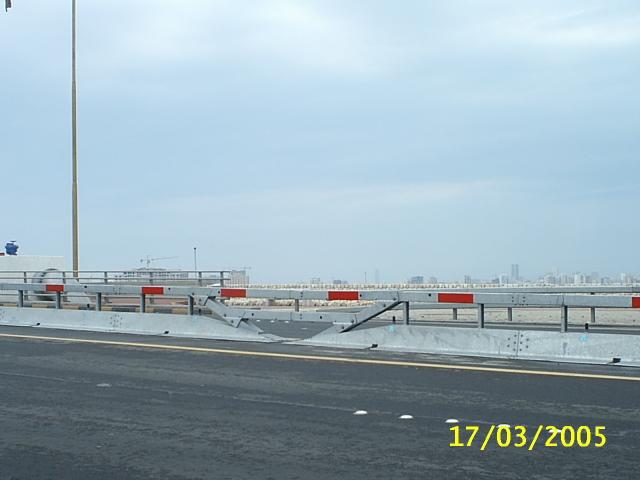
 General photo of")
6 Page 6 Components (Photos with each item) General photo of system


7 Page 7 Installation photos


8 Gate in open position Page 8 Gate section


9 Page 9 Gate hinge Fixed end section with hinge

10 Page 10 Hinge pin Upper box beam Lower box beam


11 Anchor poles Page 11 Box beam end caps


12 Page 12 Steel pins Safety clip


13 Page 13 Lifting rod Threaded Spindle
 In most cases, systems will be dispatched in containers when shipped to destinations outside of Europe. Assembly is typically done on site.")
14 Page 14 Wheels Preparing the Site a) Make sure traffic control/safety devices are positioned around the worksite in accordance with local safety regulations before work begins. b) In most cases, systems will be dispatched in containers when shipped to destinations outside of Europe. Assembly is typically done on site. Before beginning assembly, check the packing list against system components to ensure all parts are present. c) Make sure location where the GateGuard is to be installed is flat without unevenness or significant changes in cross gradient and is clear of dirt and other debris. If there is a significant unevenness, this should be rectified before installing. Unevenness can create problems when opening the gate. d) If concrete foundations are to be laid at the anchor points, this should be done at least 5 days before installation. e) It is important to determine the system s intended position in accordance to the drawings provided. Mark with a chalk line the position. Also, mark the exact centre. f) Additionally, mark 13 cm either side of the centre. (Gates have a 26 cm gap between them).
15 Page 15 Installation Step 1 a) When the truck arrives on site, offload the gate centre (diagonal) sections first placing the tip of the lower ends at the 13 cm marks. This will form a V shape. b) Then offload the gate sections. The base plates overlap one another with part of the base sliding under the other. It is important to ensure the sections are the right way round to order to do this. Use the truck s crane and crow bar to maneuver them into position. These sections are heavy and caution should be taken in keeping heads, feet and hands out of the way when offloading and positioning. Note: one section has a hinge. This section must be the last gate section with the hinge facing outwards. c) After the gate sections are in position, offload the end (fixed) sections. The hinge should be facing towards the centre and should marry up to the last gate section. Using the crane and crow bar, insert the hinge pin. d) Lastly, offload the transition sections. These are likely to have been specially made for the site and will differ in length and type. e) Other parts of the system should be left to one side for the moment. f) Check that the system fits the space allocated and there are no problems with the positioning. Step 2 The sequence of installation may change depending on site conditions but in normal circumstances, we recommend that installation starts at one end and continues towards the middle and onto the other end. DON T START AT BOTH ENDS AT ONCE. The transitions can be the difficult part of the installation. SGGT recommends that one starts with the more complicated end (if there is one). Therefore, attach one of the transitions to existing barrier and to the GateGuard fixed end. All bolts, nuts and washers are supplied and the drawings will clearly mark which ones to use. In some cases, chemical adhesive is required to secure the bolts in place. Please read the instructions detailed on the cans carefully. If adhesive is used, do not tighten the bolts for at least 6 hours. Note: Some small adjustments to the positioning of the system may be necessary either to avoid rebar or to give a better visual appearance to the transitions. Minor adjustments do not create problems.
16 Page 16 Step 3 Next, secure the end (fixed) sections to the road surface. Use the section s base as a template and drill holes through it into the road surface to the depth and diameter shown on the drawings. Clean loose dirt from the holes using compressed air and/or brush. Place a nut on an anchor bolt and drop it into each hole ensuring that the holes are deep enough for the bolt s length. Then half fill holes with adhesive supplied and insert a bolt into each hole. We recommend that a nut with washer is placed on each bolt so that the right height is achieved. To ensure good bonding, twist the bolt backwards and forwards when installing until the bolt is to the correct depth. Note: Don t attempt to tighten nuts for at least six hours to allow the adhesive to cure. Step 4 The gate sections must now be bolted together. There are many bolts and one should have several people working on tightening them. The drawings will indicate which size of bolt is required. Bolts in the base plate are smaller. Take care in lining up the lower sections before attempting to insert the bolts. Minor adjustments to the sections position may be necessary. Ensure all bolts are tightly done up. Step 5 There are two box beam rails which connect the two gates at the centre. They are held in place by steel pins. Each pin has a safety clip. The longer beam goes on top and the shorter below. Install them now. Note: One of the gate sections has a metal rod passing vertically through the top and bottom parts of it. It is not fixed in any way. Look for it. It can be removed and placed through the box beams. It is long enough for two people to use it to lift the beams. The rod simply facilitates ease of movement when one needs to move them from the closed to the open position and back. The beams will slide along the top of the gates and are secured with the steel pins. You will find holes in the first sections of the gates for this purpose. Step 6 Bolt up the second gate in exactly the same way as the first.
17 Page 17 Step 7 Install the second fixed end section as the first. Step 8 Install the second transition. In some cases, there is the need to shorten or lengthen the transition slightly to fit accurately the space available. This is usually fairly easy to do. If modifications are necessary, the site engineer should be consulted. If new holes are drilled or beams cut, the steel parts should be treated with galvanizing paint to protect them against corrosion. Step 9 a) Remove the centre box beam. Remove the plates at the base of each gate. These cover a circular hole. Mark the position the holes with chalk and move gates to one side. Using the core drilling tool, drill holes to the diameter and depth shown on the drawings. b) After removing the core, insert the metal anchor sleeve. This is sometimes a tight fit. A sledge hammer can be used to install it to the correct depth. c) Move the gates back into their original position and insert the anchor poles. d) Remove all dirt, gravel or sand which the cores may have created. The GateGuard installation for the closed position is completed. Step 10 The final step is the make the holes in the lanes to secure the gate open when required. a) Along the lower section of each gate section is a black cap. Remove them. Beneath, is a threaded spindle with a large nut. By turning this nut, the wheels can be lowered, raising the gate off the ground. Raise each wheel to the same height. b) Remove the anchor poles which are securing the gates in the closed position. Swing the gates open both to the left and right. This can easily be accomplished by one or two people. With the assistance of the site engineer, determine what positions are required when the gate is open. Depending on gate length, one will normally make holes at the outer edges of the first and second lanes closest to the GateGuard. Make a chalk marks using the gate to determine exact positions and drill_holes.
18 Page 18 c) There are several lane anchoring solutions and one should consult the drawings for the type being used on your project. In most cases, metal sleeves are inserted into the road surface at the points drilled. A cap is supplied to stop dirt getting into it. The centre anchor poles are usually used to hold the gates open. Final Checks o Close gates. o Insert anchor pins in closed position. o Replace cover plates above anchor pins. o Replace upper and lower box beams. o Replace the lift rod o Clean all dirt from site If there are any queries or the need for some help, please contact our local agent or SGGT. Our contact details are: SGGT Strassenausstattungen GmbH Customer Service Dept. Bahnhofstrasse Ottweiler Germany Tel.: Fax: export@sggt.com
Installation Instructions. Tools Needed. Tape measure. Level. Shovel or Post hole digger. Concrete. Drill. Stakes. Mallet or hammer.
 Installation Guide EcoStone Fence 1330 West 400 North Orem, UT 84057 Toll Free 1.866.648.9336 Tel. 1.801.655.5236 Fax 1.801.655.5240 www.ecostonefence.com Installation Instructions Introduction. These
BUMP GATE FITTING INSTRUCTIONS.
 1 BUMP GATE FITTING INSTRUCTIONS. HEAVY DUTY MODEL FOR STEEL POSTS. Hinge post Lock post Bump arms Two-way lock Thank you for purchasing a Bump Gate. This device will provide you with many years of good
X-TENSION 350 Guardrail End Terminal Tangent and Flared
 X-TENSION 350 Guardrail End Terminal Tangent and Flared December 2015 Table of Contents Introduction 3 System Overview 3 Before Installation 3 Limitations and Warnings 4 Safety Statements 4 Parts Identification
Introduction 3. System Overview 3. Before Installation 3. Limitations and Warnings 4. Safety Statements 4. Parts Identification 5.
 June 2015 Table of Contents Introduction 3 System Overview 3 Before Installation 3 Limitations and Warnings 4 Safety Statements 4 Parts Identification 5 Preparation 7 Soil Conditions 7 Tools Required 7
INSTALLATION INSTRUCTIONS FOR #101NS & #101QR FIXED BASE
 INSTALLATION INSTRUCTIONS FOR #101NS & #101QR FIXED BASE #165 Anchor Kit #160/161 Epoxy Kit #163 Super Bundy Plus NOTE: BITUMINOUS PRODUCTS CANNOT BE USED TO INSTALL #101 FIXED BASE Revised MAY 2010 IMPACT
X-350 Guardrail End Terminal
 X-350 Guardrail End Terminal Tangent and Flared Step by Step Instructions for the Tangent and Flared Applications Ph 0800 655 200 or visit www.csppacific.co.nz August 2011 / Page 1 Table of Contents Introduction
HOOP RACK HEAVY DUTY Setbacks WALL 36" WALL 42" 36" STREET 59" STREET Dero
 Setbacks WALL 36" WALL 42" STREET 36" 59" STREET Installation Instructions Tape Measure Marker or Pencil Masonry Drill Bit Drill (Hammer drill recommended) Hammer Wrench 9/16 Level RECOMMENDED BASE MATERIAL
CertainTeed INSTALLATION GUIDE SIMTEK FENCE PRODUCTS. Fence Installation Guide 3', 4' & 6' High
 CertainTeed INSTALLATION GUIDE SIMTEK FENCE PRODUCTS Fence Installation Guide 3', 4' & 6' High INSTALLATION GUIDE These instructions are designed to assist both professional installers and do-it-yourselfers
INSTALLATION INSTRUCTIONS
 INSTALLATION INSTRUCTIONS A CSW Industrials Company PJC Floor Pan Expansion Joint Covers The following instructions are very important. Read them carefully, and be sure you understand them completely before
Terminus TM CEN End Terminal
 Product/Installation Manual Corporate Offices: 35 East Wacker Dr., 11 th Floor Chicago, IL 60601-2076, USA Tel: +1 (312) 467-6750 Fax: +1 (312) 467-1356 http://www.energyabsorption.com/ Quixote Europe
STRATUS SHELTER. Take bike parking to new heights
 Take bike parking to new heights The Stratus Shelter is a striking bike shelter option for any transit station, university campus, or multi-family residential building project. It is constructed of American
E N G L I S H GARDEN SHED. Assembly Instructions. Suitable for Models WITH VARYING DEPTHS
 GARDEN SHED Assembly Instructions Suitable for Models 6' Wide 8' Wide 0' Wide WITH VARYING DEPTHS GI0003 November 0 INSTALLATION ADVICE It's Not That Difficult! The construction of your shed isn't as complicated
FENCE INSTALLATION GUIDE 8 HIGH WALLS
 FENCE INSTALLATION GUIDE 8 HIGH WALLS 1.866.648.9336 www.simtekfence.com INSTALLATION GUIDE These instructions are designed to assist both professional installers and do-it-yourselfers of SimTek decorative
SILVERBACK INSTALLATION MANUAL
 SILVERBACK INSTALLATION MANUAL R-SERIES SOLAR RACKS T OLL FREE 866-766-3727 WWW.ROOFSCREEN.COM Introduction... 2 The Silverback Solar Racking System... 2 This manual... 2 Application... 2 System Overview...
6a. Eight Steps to Chain-Link Fence Installation
 6a. Eight Steps to Chain-Link Fence Installation Before You Start You will need the following tools to install your chain-link fence: Post hole digger Wheelbarrow, shovel and hoe for mixing concrete Tape
Bumper Sign INSTALLATION INSTRUCTIONS
 Bumper Sign INSTALLATION INSTRUCTIONS BUMPERSIGN TOOL CHECKLIST SDS MAX Rotary Hammer Drill Marker/Pencil SDS MAX 1 Carbide Drill Bit Tape Measure Torque Wrench with ½ Drive Power Source Vacuum ½ Drive
FENCE INSTALLATION GUIDE 6 HIGH FENCE
 FENCE INSTALLATION GUIDE 6 HIGH FENCE 1.866.648.9336 www.simtekfence.com INSTALLATION GUIDE These instructions are designed to assist both professional installers and do-it-yourselfers of SimTek decorative
Independent Containment System (ICS)
") Installing the Independent Containment System (ICS) Complete these instructions to install the Independent Containment System (ICS). Prerequisites This installation requires a team of at least two people.
Installing the Independent Containment System (ICS) Complete these instructions to install the Independent Containment System (ICS). Prerequisites This installation requires a team of at least two people.
X-Tension TM Guardrail End Terminal
 Installation and Maintenance Manual X-Tension TM Guardrail End Terminal Step by Step Instructions for the Tangent, Flared and Median Applications Barrier Systems Sales and Service 3333 Vaca Valley Pkwy,
Office Installation Guidelines
 UH Structures Inc. dba Ebtech Industrial 2241 Industrial Drive Connellsville, PA 15425-6181 Telephone: 724-628-6100 Fax: 1-412-774-2429 www.ebtechindustrial.com Office Installation Guidelines INTRODUCTION
Oceanside Outdoor Vinyl Shower Kit (3 x 3 Enclosure)
") Oceanside Outdoor Vinyl Shower Kit ( x Enclosure) A B ASSEMBLY GUIDE REQUIRED FOR INSTALLATION (A) Zippity Post Extension for In-Ground Installation (Sold as 4-Packs) (B) Zippity Galvanized Steel Surface
Oceanside Outdoor Vinyl Shower Kit ( x Enclosure) A B ASSEMBLY GUIDE REQUIRED FOR INSTALLATION (A) Zippity Post Extension for In-Ground Installation (Sold as 4-Packs) (B) Zippity Galvanized Steel Surface
Swerve Rack CUSTOM RACKS AVAILABLE
 CUSTOM RACKS AVAILABLE Swerve Rack The design of the Swerve mirrors the bike frame, thus providing superior bike support while making it easy to secure both the bike frame and wheel with a standard u-lock.
The following instructions will guide you through the installation of your new vinyl railing.
 Installation Guide St. James Vinyl T-Rail Tools Required Protective eye glasses 3/8 x 3 Concrete Anchors/Fasteners (for Tape measure concrete installations) Variable speed drill/screwdriver Philips Driver
Free Standing Frame and Canopy
 Patriot Docks Free Standing Frame and Canopy Required Tools: Cordless Drill, 3/8 drill bit, 17mm wrench, 18mm wrench, 6mm hex key (included), 8mm hex key (included) Helpful Tips: Assembling and installing
INSTALLATION GUIDE DUOFUSE SLAT WALL SYSTEM
 06/2013 ENG 1 INSTALLATION GUIDE DUOFUSE SLAT WALL SYSTEM The Duofuse wood composite slat wall system is much more durable than wooden fences, and correct installation is necessary to enjoy the fences
ALUMINUM FOOTBALL GOALS INSTRUCTIONS WARNING WARNING Upright. Upright. Flag. Flag. Offset Pole.
 ALUMINUM FOOTBALL GOALS INSTRUCTIONS 800-67-090 Flag Flag Ground Sleeve Anchor Kit WARNING Football goals are shipped unassembled. Read all instructions thoroughly before attempting to assemble this equipment.
ABSORB 350 Crash Cushion Product Specifications
 ABSORB 350 Crash Cushion Product Specifications Product Specification: ABSORB 350 TL-2 Non Re-directive, Gating, Crash Cushion Applied to Permanent or Portable Concrete Barrier I. General The ABSORB 350
S W E RV E RAC K. Simple Security. Simple Stability.
 S W E RV E RAC K Simple Security. Simple Stability. The Swerve Rack is a proven design that provides high security and easy bike parking. The Swerve Rack uses thick pipe construction and the full radius
#4 Phillips Driver Bit 1/8, 4mm, 5.5mm & 8mm (5/16 ) Allen Wrench. Safety Glasses
 Allen Wrench. Safety Glasses") ATLANTIS RAIL Contact Information: Atlantis Rail Systems 70 Armstrong Road 3900 Civic Center Drive Plymouth, MA 02360 North Las Vegas, NV 89030 (800) 541-6829 or (508) 732-9191 (508) 732-9798 www.atlantisrail.com
ATLANTIS RAIL Contact Information: Atlantis Rail Systems 70 Armstrong Road 3900 Civic Center Drive Plymouth, MA 02360 North Las Vegas, NV 89030 (800) 541-6829 or (508) 732-9191 (508) 732-9798 www.atlantisrail.com
P a r k c o n s o l e s i n k a s s e m b l y i n s t r u c t i o n s
 P a r k c o n s o l e s i n k a s s e m b l y i n s t r u c t i o n s Before You Begin: Professional installation by two-person crew is required for this fixture. Install water supply and drain piping
Downtown Rack. Custom logo option available
 Custom logo option available Downtown Rack The Downtown Rack uses thick, square-tube construction that can t be cut with a pipe cutter. The extended width of the Downtown Rack makes for easy bike parking
Elo Touch Solutions Wallmounting Kit for the 7001L IDS Touchmonitors
 Installation Manual Elo Touch Solutions Wallmounting Kit for the 7001L IDS Touchmonitors SW602083 Rev E Table of Contents Chapter 1: Safety Warning... 3 Chapter 2: Kit Contents... 4 Included in Kit...
GROWING BETTER THROUGH DESIGN. 6ft Lean-To LEAN-TO. Assembly Instructions 04/02
 GROWING BETTER THROUGH DESIGN 6ft Lean-To LEAN-TO Assembly Instructions 04/02 6ft Lean-To Greenhouse Base Plan Introduction/Tools/Contents / / Contents This is a copy of our Lean-To greenhouse base plan.
Panoramic Door Block Frame Installation Manual
 Units 5 & 6 Park House Lane Sheffield S9 1XA 01142 439593 Panoramic Door Block Frame Installation Manual Panoramic Door Block Frame Door Installation Guide 10-10-17 1 of 1 Thank you for choosing Panoramic
H O O P RAC K. Simple Security
 H O O P RAC K Simple Security The Hoop Rack is a proven design that provides high security and easy bike parking. The Hoop Rack uses thick pipe construction and the full radius of the bend makes the Hoop
Installation Manual. QuadGuard System. The World Wide Standard In Crash Cushions ENERGY ABSORPTION
 The World Wide Standard In Crash Cushions ENERGY ABSORPTION SYSTEMS, INC. A Quixote Company Saving Lives By Design Corporate Offices: 35 East Wacker Dr., 11th Floor Chicago, IL 60601-2076 Telephone: (312)
Installation Instructions Kit, Base Rail Bracket Part # 31413
 Installation Instructions Kit, Base Rail Bracket Part # 31413 Dealer / Installer: Provide a copy of these Instructions to the end user of this product. These Instructions provide important operating and
RBP-1215B-RX DODGE RAM QUAD CAB RX3
 RBP-1215B-RX3 2002-2017 DODGE RAM 15-3500 QUAD CAB RX3 Passenger side RX-3 Side Step Drill Template Passenger side rear Modular Bracket (6) L Support Brackets Driver side rear Modular Bracket Driver side
Installation Guide. Capped Cellular PVC Fencing. Table of Contents. Storage and Handling Tools Needed Fence Layout and Locating Posts
 Capped Cellular PVC Fencing Installation Guide Table of Contents Storage and Handling Tools Needed Fence Layout and Locating Posts Installation instructions 4 x 4 Over Sleeve Post - 3.5 Rail Privacy Shadowbox
FABA. Installation Instructions. Conductor Bar System. Publication #FABA-03 3/1/04 Part Number: Copyright 2004 Electromotive Systems
 FABA Conductor Bar System Installation Instructions Publication #FABA-03 3/1/04 Part Number: 005-1062 Copyright 2004 Electromotive Systems 1S 100 Z Installation Instructions Contents: Basic Diagram - -
The following instructions will guide you through the installation of your new vinyl railing stair kit.
 Installation Guide Vinyl Standard Stair Railing Tools Required Protective eye glasses Tape measure Variable speed drill/screwdriver Rotary hammer or hammer drill and masonry percussion bit recommended
MSP-WRTIDSKY1 Light Weight Suspended Ceiling Kit for use with Island Display Skybox
 INSTALLATION INSTRUCTIONS MSP-WRTIDSKY1 Light Weight Suspended Ceiling Kit for use with Island Display Skybox The MSP-WRTIDSKY1 Light Weight Suspended Ceiling Kit provides a sturdy support for LCD displays
Plastibeton Trench System. Installation Packet
 Plastibeton Trench System Installation Packet Plastibeton Installation Guide This Installation Guide is intended to assist in the preparation and installation of Plastibeton products manufactured by Oldcastle
ALUMINUM POLE VAULT STANDARDS SPECIFICATIONS
 SPECIFICATIONS Specifications: All aluminum construction for superior corrosion resistance. Dual height scales provide English and Metric measurements ranging from 7' to 8'. Wide stance base for improved
Boat Lift Canopy Frame Assembly Instructions
 Patriot Docks Boat Lift Canopy Frame Assembly Instructions Helpful Tips: Assembling and installing the canopy frame and cover is a two person job. Additional help makes installation easier and is recommended.
Post & Rail Crossbuck
 Post & Rail Crossbuck 1. Getting Started 6. Crossbuck Be sure to call underground prior to digging Assemble gates (if necessary) and decide where they will be located Stake out the fence line Space and
Melamine Plastic Laminate. Toilet Partition Installation Manual
 Melamine Plastic Laminate Toilet Partition Installation Manual PHONE: FAX: 1-866-317-2786 ATTENTION DO NOT MIX FASTENER PACKS EACH FASTENER PACK HAS THE NECESSARY BOLTS, BARRELS AND SCREWS TO INSTALL THE
INSTALLATION MANUAL Sluice Gates, Stop-logs & Screens
 INSTALLATION MANUAL Sluice Gates, Stop-logs & Screens INTRODUCTION During manufacture and assembly of equipment great care is taken to ensure accuracy in mating the sealing faces on frame and doors, especially
INSTALLATION INSTRUCTIONS
 INSTALLATION INSTRUCTIONS SOLID PHENOLIC TOILET PARTITIONS 1080 DuraLineSeries Class-A Fire Rated Includes Institutional Hardware Option.67 IMPORTANT: Storage and Handling Information on last page. Review
H O O P RAC K. Simple Security
 H O O P RAC K Simple Security The Hoop Rack is a proven design that provides high security and easy bike parking. The Hoop Rack uses thick pipe construction and the full radius of the bend makes the Hoop
LAWN AND GARDEN GREENHOUSE
 MODELS# OG0AL8-BKE OGAL-8 OGrow Walk-in ' x 8' LAWN AND GARDEN GREENHOUSE With Heavy Duty Aluminium Frame MANUAL VERSION # Grow r! e h t e g To Let's Thank you for purchasing the OGROW greenhouse Follow
Portable System Owners Manual
 Portable System Owners Manual Customer Service Center N53 W24700 South Corporate Circle Sussex, WI 53089 U.S.A. Adult Assembly Required. This manual, accompanied by sales receipt, should be saved and kept
END FRAMES. End frames built using pressure treated 2x4 (1 1/2" x 3 1/2") 36" 34" 7/16" pilot hole. 5 1/2" x 1/2" lag bolt 8" wheel 23"
 36 34 7/16 pilot hole. 5 1/2 x 1/2 lag bolt 8 wheel 23") END FRAMES End frames built using pressure treated 2x4 (1 1/2" x 3 1/2") 23" 17 1/2" (B) (B) Measure from the bottom of your stone to 1" below the lip to get your measurement. 17 1/2"(B) 36" 34" 1/2" flat
END FRAMES End frames built using pressure treated 2x4 (1 1/2" x 3 1/2") 23" 17 1/2" (B) (B) Measure from the bottom of your stone to 1" below the lip to get your measurement. 17 1/2"(B) 36" 34" 1/2" flat
10x10 Trellis Pergola
 0x0 Trellis Pergola ASSEMBLY GUIDE Ver.0-7 Table of Contents PAGE Introduction & Overview...................................................... Pergola Materials Overview..............................................................
Installation Instruction
 Tools Needed for Assembly Stud finder (for wood stud wall) Pencil Mark Electric drill Wood Stud Wall Installation Step 1. Locate the Wood Studs Installation Instruction Drill bit (for wood stud wall) Masonry
ASSEMBLY INSTRUCTIONS FOR STORETTE STA42
 ASSEMBLY INSTRUCTIONS FOR STORETTE STA42 A01 CAUTION: Some parts have sharp edges. Care must be taken when handling the various pieces to avoid a mishap. For safety sake, please read the safety information
INSTALLATION INSTRUCTIONS FOR SL-LB MANUAL LIFT BARRIER GATE ARMS
 INSTALLATION INSTRUCTIONS FOR SL-LB MANUAL LIFT BARRIER GATE ARMS Questions? Call 520-780-9751 or visit our website at: www.barriergatearm.com YOUR SL-LB MANUAL LIFT BARRIER GATE ARM WILL ARRIVE WITH WEIGHT
1. Layout. Step 1. Step 2. Step 3. Fig. 1
 1-3/8 Panel Clamp Tools You Will Need: Tape Measure, Mason s String, Stakes, Hole Digger, Shovel, Level, Wheelbarrow, Wrenches or Adjustable Wrench, Hacksaw, Pliers, Cutting Pliers, Fence Stretcher and
Installation of Balustrade Systems
 Installation of Balustrade Systems IMPORTANT: Be sure to mark the center point of each newel post's location prior to installation to insure proper spacing. All product interfaces must use PL Premium Adhesive
Installation Manual Using StairFurb Handraail Version 5.1 OCT 2017
 Installation Manual Using StairFurb Handraail Version 5.1 OCT 2017 ORDER OF ASSEMBLY TOOLS YOU WILL NEED - Fine Saw - Sander - Wood Filler - Allen keys - Screw Driver - Drill - Suitable Screws PROTECTING
Warnings. Description. Prior to Installation Tools Needed
 Warnings Failure to act in accordance with the following may result in death or personal injury. The JT Strong Arm Stabilizer System is intended to eliminate chassis movement in travel trailers and fifth
Fig. 2 DORMA-Glas Stand/Issue 02/03 Seite/Page 1/7
 FSW Installation instructions Track rail 75 x 72 mm 1. Ceiling substructure and installation of the track rail (Fig. 1): The track rail must be bolted over its entire length (including the stacking track
Frameless Inline Door With Return QCI5263
 INSTALLATION INSTRUCTIONS Frameless Inline Door With Return QCI5263 WALL MOUNT HINGES FRAMELESS DOOR / PANEL / RETURN PANEL QCI5263 REV. 0 Page 1 Certified 06/17/2016 Parts List with wall mount hinges
Pvcu Bi Folding Doors Fitting Instructions.
 Pvcu Bi Folding Doors Fitting Instructions. THE FOLLOWING INSTRUCTIONS ARE GIVEN IN GOOD FAITH AND ARE FOR GUIDANCE ONLY. NO RESPONSIBILITY WILL BE ACCEPTED FOR ANY MIS- INTERPRETATION. WHEN INSTALLING
INSTALLATION INSTRUCTIONS
 INSTALLATION INSTRUCTIONS HIGH PRESSUE LAMINATE (HPL) TOILET PARTITIONS 1030 TrimLineSeries 1040 DesignerSeries Includes continuous hardware option.65. IMPORTANT: Storage and Handling Information on last
SHADOWBOX INSTALLATION FOR: Standard 6 H x 8 W Shadowbox Fence 5 x 5 Routed Posts Dog Ear or Straight-Edge Pickets 1.75 x 3.5 Rail
 SHADOWBOX INSTALLATION FOR: Standard 6 H x 8 W Shadowbox Fence 5 x 5 Routed Posts Dog Ear or Straight-Edge Pickets 1.75 x 3.5 Rail Storage and Handling Fence Preparation and Layout Locate and Set Posts
PUSH-PULL-PROPS. and accessories ROBUSTA-GAUKEL GMBH MOUNTING TECHNOLOGY &CO.KG
 PUSH-PULL-PROPS and accessories MOUNTING TECHNOLOGY ROBUSTA-GAUKEL GMBH &CO.KG MOUNTING TECHNOLOGY PUSH-PULL-PROPS AND ACCESSORIES INDEX General information...................... 3 Push-pull-prop Type
YUKON PATIO COVER INSTALLATION INSTRUCTIONS
 YUKON PATIO COVER INSTALLATION INSTRUCTIONS Before You Begin: Consult your local building department for any required permits You may be required to obtain a building permit for this structure. Contact
Item 550 Chain Link Fence
 Item Chain Link Fence 1. DESCRIPTION 2. MATERIALS Furnish, install, remove, repair, or replace chain link fence and gates. Furnish certification from the chain link fence materials manufacturer stating
HANDLING AND ASSEMBLY INSTRUCTIONS FOR TRUE FOCUS 3.0M, 3.8M AND 4.2M ANTENNAS WITH POLAR MOUNT
 HANDLING AND ASSEMBLY INSTRUCTIONS FOR TRUE FOCUS 3.0M, 3.8M AND 4.2M ANTENNAS WITH POLAR MOUNT Introduction SECTION 1 Thank you for purchasing one of our fine True Focus products. This manual covers the
LOFT DOOR HANGER BARN DOORS & HARDWARE. Hardware Installation Instructions. Page
 LOFT DOOR HANGER Page 1 Specifications 2 7/16" 3/8" 1-1/2 1-3/4 Ø3 3 7/8" 11-1/16 Page 2 Parts and Tools Tools Needed Tape Measure Pencil Drill with 1/8, 1/4 and 3/8 bits, 1 spade bit and Phillips bit
Assembly Instructions
 Unite Panel System Hinge Door July 2016 #12 x / slotted hex washer head bolt Figure 1 threshold bracket frame Detail F threshold bracket threshold bracket (installed) #12 x / slotted hex washer head bolt
TS-20KD-1010 LOW PROFILE CARGO SCALE INSTALLATION GUIDE
 TS-20KD-1010 LOW PROFILE CARGO SCALE INSTALLATION GUIDE Triner Scale & Mfg. Co., Inc. 8411 Hacks Cross Rd. Olive Branch, MS 38654 Phone: 800-238-0152 Fax: 662-809-2386 Description The Triner Scale Model
Dura-Lock Roof System
 DLR-14 Dura-Lock Roof System Assembly and Installation Instructions Read the instructions before starting the job. They explain the steps required to produce a finished product that will meet factory specifications.
LAWN AND GARDEN GREENHOUSE
 MODEL# OGAL-66 OGrow Walk-in 6' x ' LAWN AND GARDEN GREENHOUSE With Heavy Duty Aluminium Frame Let'sGrow Together! Thank you for purchasing the OGROW greenhouse Follow the assembly and safety instructions
CHEVY SuperBracket Mounting Kit #0826
 CHEVY SuperBracket Mounting Kit #0826 #1200 SuperGlide (16K) #0800 SuperGlide (20.5K) Gross Trailer Weight (Maximum) Vertical Load Weight (Max. Pin Weight) 16,000 lbs. 4,000 lbs. Gross Trailer Weight (Maximum)
Calf-Tel Pen System Assembly Instructions
 Calf-Tel Pen System Assembly Instructions (Instructions work for 4, 6, and the 7 Pen Systems) 1 ASSEMBLY OF PEN FRONT AND WALLS START THE ASSEMBLY BY LINING UP THE TWO UNI-DIRECTIONAL ARROWS IN THE TOP,
INSTALLATION INSTRUCTIONS HEAVY DUTY TILT WALL MOUNT Model: PPH-2000
 INSTALLATION INSTRUCTIONS HEAVY DUTY TILT WALL MOUNT Model: PPH-2000 Specifications: Accomodates Akira and Orion 84" displays without interface bracket; accomodates other large flat panel displays with
General Guidelines:
 ASSEMBLY INSTRUCTIONS Congratulations on your new Patriot Dock purchase. This manual contains instructions to assemble basic dock configurations for use at typical residential shoreline application. Please
S H E D A S S E M B L Y I N S T R U C T I O N S
 T I T A N R A N G E S H E D A S S E M B L Y I N S T R U C T I O N S 8 X 10 ft Approx = 2550 x 3140 cm COMPONENT LIST Component illustrations are given as a visual guide only and are not in proportion PART
7141 & NATIONAL POLE VAULT STANDARDS SPECIFICATIONS
 SPECIFICATIONS Specifications: This standard has a clamping system and a handle added for ease of operation. The clamping system is above the base pad protectors when in the lowest position and the tightening
INS A KSCR INSTALLATION INSTRUCTIONS STANDARD PROCEDURE. 1. Unpacking the KSCR Splicing the KSCR (If Required)...
...") INS-88.500-0A KSCR INSTALLATION INSTRUCTIONS STANDARD PROCEDURE 1. Unpacking the KSCR... 2 2. Splicing the KSCR (If Required)... 4 3. Assemble Curb and Rail Corners... 5 4. Install Cross Bracing (If Required)...
INS-88.500-0A KSCR INSTALLATION INSTRUCTIONS STANDARD PROCEDURE 1. Unpacking the KSCR... 2 2. Splicing the KSCR (If Required)... 4 3. Assemble Curb and Rail Corners... 5 4. Install Cross Bracing (If Required)...
INSTALLATION INSTRUCTIONS
 INSTALLATION INSTRUCTIONS LAMINATED P LASTIC TOILET PArTITIONS 1540 ClassicSeries with Options IMPORTANT: Storage and Handling Information on last page. For faster, easier installation, please review these
REC Series Rack Installation Guide
 REC Series Rack Installation Guide 1 REC Series Rack Installation Guide TABLE OF CONTENTS SECTION SAFETY WARNINGS 1 600 WIDE EXPLODED VIEW 2 800 WIDE EXPLODED VIEW 3 SWITCHING DOOR HANDING 4 STABILIZING
INSTALLATION INSTRUCTIONS
 INSTALLATION INSTRUCTIONS SHOWER PROFESSIONAL SERIES Round Sliding Englefield has a history of making superb showers and their popularity is testament to their quality and affordability. It s the details
Greenhouse Assembly Instructions
 Greenhouse Assembly Instructions Our Help Line provides support and advice to customers of Summer Garden Buildings after ordering. For advice before you buy you can phone us free 7 days a week on 0800
Shetland Stalls Installation Instructions
 Shetland Stalls Installation Instructions RAMM Horse Fencing and Stalls 13150 Airport Hwy. Swanton, OH 43558-9615 1-800-434-8456 Rev. 1/9/18 Before you start Kit can accommodate up to 12 wide stall front
12 x 12 Flat Top Pergola
 x Flat Top Pergola Model: Regency, Roosevelt A S S E M B L Y G U I D E O P T I O N A L A C C E S S O R Y Bolt Down Bracket Kit ( for Pergola) Ver./MAR 0 Ta b l e o f Co n t e n t s PAGE x Flat Top Pergola
The Festival Assembly Instructions
 The Festival Assembly Instructions Toll Free: 866.768.8465 Hours: 9-5 Monday-Friday EST www.homeplacestructures.com Package ships as shown CONTACT INFORMATION: HomePlace Structures 301 Commerce Drive New
IMPORTANT -- SPECIAL INSTALLATION INSTRUCTIONS
 IMPORTANT -- SPECIAL INSTALLATION INSTRUCTIONS ** READ ALL INSTALLATION INSTRUCTIONS BEFORE STARTING!** If at any point, you have questions, call 1-800-851-0865...(The manufacturer will not be responsible
6 1/2 x 6 1/2 Flat Top Pergola
 6 / x 6 / Flat Top Pergola A S S E M B L Y G U I D E Models: Portland, Liberty O P T I O N A L A C C E S S O R Y Bolt Down Bracket Kit V.-0506 Ta b l e o f Co n t e n t s PAGE The Introduction & Overview......................................................
SADDLE BUDDY EASY ASSEMBLY. The Saddle Buddy is easy to install Galvanized Surface In-Ground. Rail.
 SAD D L E B U D DY Saddle Up. Designed for trailheads, bike parks and picnic areas, the Saddle Buddy offers a resting place for cyclists noble steeds. The convenient bar allows cyclists to keep their bikes
Installation Instructions for. Before You Begin TOOLS REQUIRED
 Composite Railing System STEP-BY-STEP Installation Instructions for Spectrum Composite Railing Virtually maintenance free 20-year warranty EverNew Spectrum Railing system is designed to work with a number
RUN-IN SHED INSTRUCTIONS
 RUN-IN SHED INSTRUCTIONS 14321 5th Line Nassagaweya, Rockwood, ON, N0B 2K0 Phone 519-856-9959 ~ Fax 519-856-4141 Toll Free 1-800-461-3362 ~ Email sales@systemhorse.com Website www.systemfence.com RUN-IN
CONSTRUCTION GUIDE 27ft Wide and 30ft Wide SHEEP HOUSE
 The Outside, Inside CONSTRUCTION GUIDE 27ft Wide and 30ft Wide SHEEP HOUSE Thank you for purchasing a Premier Sheep House. Please take the time to carefully read through this Construction Guide before
Thread protection accessories are installed at the MODIX production factory and delivered with couplers.
 Installation of MODIX Rebar Coupler Identification of the product The type of MODIX Rebar Coupler can be identified by the marking on the product. Size of the Coupler can be identified also according to
Gared Pro-S Portable Backstop
 Models: 9616 & 9618 Installation, Operation and Maintenance Instructions Please read all instructions before attempting installation or operation of these units SAVE THESE INSTRUCTIONS FOR FUTURE USE PUBLICATION
Installation for Full Size Polaris Ranger Crew Doors
 Installation for Full Size Polaris Ranger Crew Doors Order of Installation: Heater Doors Wiper on to Windshield Windshield Top & Back Panel Note: Most of the steps in these instructions need to be repeated
Rugged Ridge Engine Transmission Skid Plate JK
 Installation Time: 1-2 Hours Tools Required: Rugged Ridge Engine Transmission Skid Plate 2012-2017 JK Sockets: 16mm, 17mm, 18mm deep well Socket Wrench Wrenches: 16mm, 18mm Torque Wrench Drill ½ Drill
Ranch Rail Vinyl Fence
 Ranch Rail Vinyl Fence INSTALLATION INSTRUCTIONS These instructions are to be used as general guidelines for the installation of your vinyl fence under normal installation conditions. Local conditions