MECH 313 Engineering Drawing & Design
|
|
|
- Edgar Hall
- 5 years ago
- Views:
Transcription
1 1 MECH 313 Engineering Drawing & Design Lecture 11 Gears and Drawing quality assurance


2 2 Power Transmission Capacity Selecting the Spur Gear Drive
3 3 Power Transmission Capacity Selecting the Spur Gear Drive
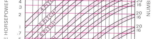
4 4 Power Transmission Capacity Selecting the Spur Gear Drive Example 3 - A 7.5-kW, 900-rpm motor is attached by means of 14.5 spur gears to a punch that operates 24 hours a day. The reduction in rpm is 4:1. Select a gear and pinion assuming that the punch is being operated at motor capacity. Solution - The operating conditions of the machine are such that the machine fits into the service class 3 and requires a service factor of 1.3. Therefore kw required for design purposes = 7.5 X 1.3 = 9.75 kw The pinion is mounted on the motor and runs at 900rpm. Refer to Fig B. Reading vertically on the 900rpm line and horizontally at 9.75 kw, we may select either a pinion having MDL = 5.08 and N = 20 or a MDL = 6.35 and N = 16. First, using a module of 5.08, we have:


")

5 5 Power Transmission Capacity Selecting the Spur Gear Drive Pinion: N = 20, MDL = 5.08, PD = N X MDL = 20 X 5.08 = 101.6mm Gear rpm = 900/4 = 225 rpm Gear: N = 4X20= 80, MDL = , PD = N X MDL = 80 X 5.08 = 406.4mm (Ratio of no. of teeth is the inverse ratio of rpm s) Second, using a module of 6.35, we have: Pinion: N = 16, MDL = 6.35, PD = N X MDL = 16 X 6.35 = mm Gear: N = 4 X 16 = 64, MDL = 6.35, PD = N X MDL = 64 X 6.35 = mm
6 6 Power Transmission Capacity Selecting the Spur Gear Drive Since both sets of gears are of the same diameter, the overall size is not a factor. Checking on the cost per set, we find that there would be considerable savings by selecting the gear and pinion having the module of Since the extra strength of the gear set having a module of 6.35 is not required in this instance, we recommend the gear and pinion having a module of 5.08.
7 7 Rack and Pinion Rack is straight bar having teeth that engage in spur gear It is a spur gear having infinite Pitch diameter all circular dimensions become linear Addendum, dedendum and thickness are same as mating gear


8 8 Rack and Pinion Divide pitch line into distances equal to Layout addendum and circular pitch in the gear dedendum d d from pitch line Divide the space by half to get linear thickness. From these points draw faces at pressure angles Complete top and bottom lines with fillet


9 9 Bevel Gears Used to transmit power between 2 shaft that intersect at any angle, most common being 90 The teeth have same shape, except on a cone instead of cylinder Miter gears have same DP, MDL and PA and number of teeth Miter gears operate in 1:1 ratio

10 10 Bevel Gears Working Drawings of Bevel Gears As in spur, the working drawings of bevel gears have dimensions only on the blank. The teeth information is given in a table Single sectional view is mostly used, and second view is drawn if needed to show details of spokes and web Both gear and pinion are drawn together sometimes to show the relationship The dimensions and teeth information - based on the teeth cutting method; but generally shown as in


11 11 Bevel Gears Working Drawings of Bevel Gears The actual gear teeth are often shown on assembly and display drawings Most common convention for drawing the teeth is Tredgold method (20-6-4) An arc whose radius taken on the back cone is used as a pitch circle and tooth is developed using spur gear formulas Tooth sizes taken on the OD and pitch dia are transferred to top view, and profiles of the teeth are drawn Radial lines from these points are used for small end of the teeth


12 Bevel Gears Working Drawings of Bevel Gears Teeth on the other views can be drawn by yprojection The tooth cross-section at the largest part of the tooth is identical to the spur gear with PD of 2* r b, and with an imaginary i N equal to 2π*r b / Circular Pitch of the bevel gear (p = πd/n) ) 12 For durability, pinion is made of stronger material as teeth in pinion comes in contact more times than the teeth th in the gear Common combinations are steel and cast iron, or steel and bronze
13 13 Worm and Worm Gears Transmit power between 2 shaft at right angles but not intersecting Teeth on the worm are similar to the teeth on the rack and teeth on the worm gear is curved to conform with the teeth on the worm Thread terms pitch and lead are used for the worm
 50:1 is preferred max, single threads are inefficient to transmit power (low helix) So")
14 14 Worm and Worm Gears Single thread worm in one revolution advances the gear by 1 tooth (a large velocity reduction is possible) Ratio of gear to worm speed is number of teeth on worm gear and number of threads on the worm (33 teeth worm gear on worm with multiple thread of 3 has a ratio of 11:1) 50:1 is preferred max, single threads are inefficient to transmit power (low helix) So multiple threaded (up to 8) worms are used
15 15 Worm and Worm Gears Figures to provide the data on work gear drawings and formulas


16 16
17 17 Worm and Worm Gears Working Drawing of Worm and Worm Gears Similar to other gears, one view drawing is used mostly, and if second view is needed, the throat and root circles are shown in solid lines When worm and gear are drawn on assembly, both views are shown; solid line for worm OD and broken lines for the gear throat dia where the teeth mesh
18 18 Chain, Gear, Belt Drives Comparison Chains - A chain drive consists of an endless chain whose links mesh with toothed wheels, called sprockets, which are keyed to the shafts of the driving and driven mechanisms Roller Chains - The unique feature of a roller chain is its freedom of joint action during its engagement with the sprocket. This is accomplished by articulation of the pins of the bushings, while the rollers turn on the outside of the bushings, thus eliminating rubbing action between the rollers and the sprocket teeth Silent Chains - Comparable ease of joint action occurs in the engagement of the silent chain with the sprocket
19 19 Chain, Gear, Belt Drives Comparison Gears - A simple gear drive consists of a toothed driving wheel meshing with a similar driven wheel. Tooth forms are designed to ensure uniform angular rotation of the driven wheel during tooth engagement. Gears are available with precision-cut teeth or with unfinished teeth Belts - A belt drive consists of an endless flexible belt that connects two wheels or pulleys. Belt drives depend on friction between the belt and the pulley surfaces for the transmission of power. In the case of V-belts, the friction for the transmission of the driving force is increased by wedging g the belt into the grooves on the pulley V-belt drives are available in single or multiple strands for varying power transmission requirements. Another type of belt has shallow teeth molded on the inside of the driving face. The pulleys have teeth for engagement with the belt teeth
20 20 Chain, Gear, Belt Drives Chain Drives Compared with Gear Drives Advantages of Chains - Shaft center distances for chain drives are relatively unrestricted, whereas with gears, the center distance must be such that the pitch surfaces of the gears are tangent. This advantage often will result in a simpler, less costly, and more practical design Chains are easily installed. Although all drive media require proper installation, the assembly tolerances for chain drives are not as restricted as those for gears. The resultant savings in the time of installation may be an important factor in meeting the production schedule required of the driven machine The ease of chain installation is a definite advantage when later changes in design, such as speed ratio, capacity, and centers, are anticipated
21 21 Chain, Gear, Belt Drives Chain Drives Compared with Gear Drives Advantages of Gears - When space limitations require the shortest possible distance between shaft centers, a gear drive is usually preferable to a chain drive Chain Drives Compared with Belt Drives Advantages of Chains - Chain drives do not slip or creep as do belt drives. So, chains maintain a positive speed ratio between the driving and the driven shafts, and no power is lost because of slippage Chain drives are more compact. For a given capacity, a chain will be narrower than a belt, and sprockets will be smaller in diameter than pulleys; thus the chain drive will occupy less overall space Chains are easy to install. Installed by wrapping it around the sprockets and then slipping the pins of a connecting link into position
22 22 Chain, Gear, Belt Drives Chain Drives Compared with Belt Drives The required minimum arc of contact is smaller for chains than for belts. This advantage becomes important as the speed ratio se and thus permits chain drives to operate on shorter shaft center distances Where several shafts are to be driven from a single shaft, positive speed synchronism between the driven shafts is usually imperative. For such applications, chains are more suitable Chains do not deteriorate with age; nor by sun, oil, and grease. They can operate at higher temperatures and are practical for low speeds Chain elongation resulting from normal wear is a slow process; the chain therefore requires infrequent adjustment. Belts stretch, which necessitates frequent tightening by shaft adjustment, by idlers, or by shortening the belt
23 23 Chain, Gear, Belt Drives Chain Drives Compared with Gear Drives Advantages of Belts - Since no metal-to-metal to contact occurs between a belt and pulleys, belts require no lubrication, although leather belts need periodic applications of belt dressing to preserve their flexibility Generally speaking, a belt drive operates with less noise than a chain drive Flat-belt drives can be used where extremely long center distances would make chain drives impractical. In the extremely high-speed ranges, flat belts can be operated to better advantage than chains


24 24
25 25 Drawing Quality Assurance Requirements of engineering drawings completeness Clarity Accuracy Standard considerations Functionality Knowledge of Design Requirements Manufacturing process Drafting practices Parts and assemblies
26 26 Drawing Quality Assurance Review Considerations Typical items for preparation and review of drawings Applied Surface Finish: Must be completely defined Expansion: Dimensions and Tolerances should be adjusted for thermal expansion or contraction during operation Inspection Processes: Such as Magnetic particle, Fluorescent penetrants, and X rays must be noted on the drawing (where required) Interchangeability: requirements must be considered d Locking features: for the retention of parts, such as Lock-wire holes, Tab washer slots, should be shown where required Material: Proper material and heat treatment must be specified
27 27 Drawing Quality Assurance Review Considerations Protective Finish: Protective finish specifications, such as painting or plating, should be specified Service: Accessibility must be provided for servicing, assembling, inspection, and adjustment Strength: Design must adequately meet all stress requirements, such as thermal, dynamic, and fatigue stresses. Deterioration (embrittlement, corrosion and wear) must be considered. Surface Texture (Roughness): Surface texture values must be specified for all surfaces requiring control. The values shown should be compatible with overall design requirements Tolerances: indicated by the linear/angular dimensions and by local, general notes must ensure proper assembly and function
28 28 Drawing Quality Assurance Drawing Considerations Abbreviations: Should conform to the country's, or the individual company's, drawing standards Dimensions: The part must be fully dimensioned and the dimensions clearly positioned Draft Angle and Radii: Proper draft angles, fillets, and corner radii should be specified Geometric Surface Relationship: Such as straightness, runout, squareness, and parallelism must be shown Revisions: All revisions must be properly recorded. All related drawings should be revised to conform
29 29 Drawing Quality Assurance Drawing Considerations Scale: The drawing should be to scale, and the scale should be identified. Must be indicated d if not to scale Surface Texture Symbols: Surface texture symbols and values must be specified for all surfaces requiring control Symbols: Whenever possible, symbols should be used in lieu of words Symmetrical Opposite parts: an AS SHOWN or OPPOSITE HAND with proper p numbers must be shown for all parts Tolerances: selection of tolerances should be carefully considered. As liberal as the design will permit Views: Sufficient i full and sectional views must be shown
30 30 Drawing Quality Assurance Fabrication Considerations Adhesives: Type of joint and adhesive used Brazing, Soldering, and Welding: Local or general notes or symbols to indicate method of fabrication Casting: Sufficient tolerances must be provided for draft, warpage, core shifting, or crossing of the parting line Economy: should be considered without sacrificing quality Forged and Molded Parts: sufficient tolerances must be allowed for die shift, die closure and warping Processing Clearance: Design must allow sufficient clearance for drills, cutters, grinding wheels, as well as welding, riveting, and other processing tools
31 31 Drawing Quality Assurance Fabrication Considerations Special Considerations: Notes for sandblast, vapor blast, and any other special operations should be included where required Holes: tolerances to be adequate to permit economical drilling and blind holes to be deep enough to permit threading Machine Lugs: when part is cast or forged, manufacturing must be facilitated by providing clamping lugs and locating pads. Removal of such lugs to be noted on drawing (where required) Tooling: Dimensions on drawings should reflect the use of standard tooling, such as reamers, cutters, and drills, wherever possible, without specifically calling out the type of tooling to be used, for example, 6.30, not 6.30 DRILL
32 32 Drawing Quality Assurance Installation Considerations Assembly: Parts should be designed so there is no possibility of misassembly. Often an offset bolt hole, or similar feature can be provided to ensure correct assembly. The design should permit servicing Clearance: The part must have sufficient clearance with surrounding parts to permit assembly and operation Driving Feature: Threaded parts require a slot, hex, or other driving feature Puller Feature: Where a part has a tight fit, it may require a puller lip, a jackscrew thread, a knockout hole, or some similar feature Tool Clearance: Adequate clearance must be provided for wrenches or other assembly tools Torque Values: Required wrench torque values should be specified where items are assembled by means of bolts, cap screws, nuts, or similar features
33 33 Functional Drafting Basic function of drawing is to provide sufficient information to produce, or to assemble parts. For the evaluation of drawing the following questions should be answered: 1. What is the purpose of the drafting shortcut? 2. Is it a personal preference disguised as a project requirement? 3. Does it meet contractual requirements? 4. Will this se costs of manufacturing, purchasing, or inspection? 5. Is it an effective communication link? 6. Are facilities available to implement it? 7. Does the shortcut bypass a real bottleneck?
34 34 Functional Drafting Procedural Shortcuts A number of procedural shortcuts, if properly applied and carefully managed, can shorten the drawing preparation cycle and result in savings Streamlined Approval Requirements It is obvious that the more signatures required on a drawing, the greater the delays in releasing data. The decision as to who will approve drawings and drawing changes must be carefully considered to make certain that all necessary functions have been taken into account (checkers, responsible engineers, important technical specialists, etc.) without imposing undue restrictions. Project ground rules and contractual requirements also play an important part in this decision
35 35 Functional Drafting Procedural Shortcuts Eliminating the Drawing Check from the Preparation Cycle One of the most common suggested shortcuts, usually proposed when a project is behind schedule or exceeding its budget or when experienced personnel are involved, is to eliminate checking from the drawing preparation cycle. Using Standard and Existing Drawings Drawings of parts are constantly being prepared that are repetitions of existing drawings. If the drafter were to incorporate into the new drawing the existing design parts, time is saved. Good drawing application records and an efficient multiple-use drawing system can eliminate duplication. Standard tabulated drawings may be used to eliminate hundreds of drawings (Figs and )
36 36


37 37
38 38 Functional Drafting Procedural Shortcuts Standard Drafting Practices Standard drafting practices are obviously the backbone of efficient drafting room operations. The best way to establish and implement these practices is through a good drafting room manual, with requirements that must be strictly observed by all personnel The drafting room manual should contain data on the use and preparation of specific types of drawings, drawing and part number requirements, standard and special drafting practices, rules for dimensioning and tolerancing, specifications for associated lists, and company procedures for the preparation, handling, release, and control of drawings
39 39 Functional Drafting Procedural Shortcuts Team Drafting Many engineering departments have turned out drawings by the method of one drafter to one drawing. Team drafting involves a number of people producing one drawing. This approach may seem uneconomical, it is faster, with visible cost savings. Some firms use to better utilize skill levels. It is a training program through h which h drafting skills are improved Data Retrieval The use of microform reader-printers provides quick and ready access to standard drawings and parts. Microfiche cards can hold up to 70 pages of information. However, for this method to be effective, a full-time librarian is needed
40 40 Functional Drafting Procedural Shortcuts Standard Parts and Design-Standard Information Encouraging the use of standard parts and approaches to design not only saves drafting time but will cut costs in purchasing, material control, and manufacturing. The odd-size cutout that requires special tooling, the design that calls for nonstandard hardware, and the equipment that uses a wide variety of fasteners when only one or two would suffice are typical cases for which properly applied standards would reduce both time and cost Training Programs To provide drafters with standard procedures and technical information is not enough; drafters must be trained in their use. New drafters are frequently overwhelmed by a strange environment.

. When a drafter needs a copy, work is delayed until the copy is made available.")
41 41 Functional Drafting Procedural Shortcuts Old employees fail to keep up with new requirements or properly use the services available. Training programs for the indoctrination of new personnel and the updating of long-service employees are rewarded by more efficient and versatile operation Copying Machines One of the most important time-saving devices, which should be available in every drafting area, is a copying machine for reference copies, checking prints of work in preparation, and similar uses (Fig ). When a drafter needs a copy, work is delayed until the copy is made available. Therefore, a good copying machine will soon pay for itself in drawing hours saved
42 42 Functional Drafting Reducing the Number of Drawings Required The cost of a project is, to some extent, directly related to the number of drawings-that must be prepared. Therefore, careful planning to reduce the number of drawings required can result in significant savings. Some ways to reduce the number of drawings are explained in the following sections.
43 43 Functional Drafting Reducing the Number of Drawings Required Detail Assembly Drawings in which parts are detailed in place on the assembly (Fig ), 4) and multi-detail assembly drawings, in which there are separate detail views for the assembly and each of its parts, will reduce the number of drawings required. However, these drawings must be used with extreme care. They can easily become too complicated (discussed Unit 14-8) Selecting the Suitable Type of Projection to Describe the Part The selection of the type of projection (orthographic, or oblique) can increase the ease with which some drawings can be read and, in many cases, reduce drafting time. For example, a single-line piping drawing drawn in isometric projection simplifies an otherwise difficult drawing problem in orthographic projection (Fig ).
44 44 Functional Drafting Reducing the Number of Drawings Required
45 45 Functional Drafting Simplified Representations in Drawing The steady rise of simplified representation in drawings prompted the ISO to prepare standard that lists the methods of simplified representation in general use for detail and assembly drawings Simplified representation is not new. Thread and pipe symbols are two examples in use for many years. Promoting and using simplified representation has many advantages. Simplified representation: 1. Raises the design efficiency 2. Accelerates the course of design 3. Reduces the workload in the drafting office 4. Enhances legibility of the drawing, so as to meet the requirements for drawings in computer: graphics and micro copying
46 46 Functional Drafting Simplified Representations in Drawing In addition to the following recommendations, with figures illustrated on the next page, simplified features are shown in this text where the appropriate drawing practices are explained. 1. Avoid unnecessary views. One or two may be sufficient 2. Use simplified drawing practices, as described throughout this text, especially on threads and common features 3. Symmetry symbol means all dimensions are symmetrical to that line 4. Complicated parts are best described by means of a drawing. However, notes can complement the drawing, thereby eliminating views that are time consuming to draw (Figs and )
47 47 Functional Drafting Simplified Representations in Drawing
48 48 Functional Drafting Simplified Representations in Drawing 5. When a number of holes of similar size are to be made in a part, there is a chance that the person producing the part may misinterpret the diameter of some of the holes. In such cases, the identification of similar-size holes should be made clear (Fig ) 6. A simplified assembly drawing should be used for assembly purposes only. Some means of simplification are: Standard parts, like nuts, bolts, and washers, need not be drawn Small cast part fillets and rounds need not be shown Phantom outlines of complex details can be used
49 49 Functional Drafting Simplified Representations in Drawing 7. Use symbol libraries 8. Eliminate hidden lines that do not add clarification 9. Show only partial views of symmetrical objects (Fig ) 10. Eliminate views when the shape or dimension can be given by description, for example,,, HEX, or THK
50 50 Functional Drafting Reproduction Shortcuts Reproduction techniques have been developed which, if properly used, can greatly reduce drawing preparation time An understanding of available techniques and their limitations, supported by the close cooperation of a reproduction group familiar with drafting operations, can help the drafting supervisor make significant cost savings. New Drawings Made from Existing Drawings When a new drawing is to be made from an existing drawing with few changes, CAD makes this task easy by simply py removing the unwanted material and drawing in the new
51 51 Functional Drafting Photodrawings Engineering drawings into which one photograph, or more, is incorporated, have increased in popularity because they can sometimes present a subject even more clearly than conventional drawings Photodrawings supplement rather than replace conventional engineering drawings by eliminating much of the tedious and time-consuming effort involved when the subject is difficult to draw They are particularly useful for assembly drawings, piping diagrams, large machine installations, switchboards, and so forth, provided, of course, that the subject of the drawings exists so that it may be photographed
52 52 Functional Drafting Photodrawings Photodrawings are also a comprehensive means of transmitting technical information; they free the drafter from having to draw things that already exist (Fig ). 10). Photodrawings are easy to make and usually take much less time to prepare than an equivalent amount of conventional drafting Background Any photodrawing must begin with a photograph of an object, a part or assembly, a building, a model, or whatever else may be the subject of the drawing Photography The best photographic angle usually is one that shows the subject in a flat view with as little perspective as possible. (If the situation calls for a perspective, select the angle that best describes the object.) Make certain that all the parts important are in view


53 53 Functional Drafting Photodrawings
54 54 Detail Drawings Drawings may be classified into two groups: detail drawings, which provide the necessary information for the manufacture of the parts, and assembly drawings, which supply the necessary information for their assembly Since working drawings may be sent to another company to make or assembly the parts, the drawings should conform with the drawing standards of that company. For this reason, most companies follow the drawing standards of their country. The drawing standards recommended by ASME have been adopted by the majority of industries in the United States
55 55 Detail Drawings Detail Drawing Requirements A detail drawing (Figs and ) must supply the complete information for the construction of a part. This information may be classified under three headings: shape description, size description, and specifications Shape Description This term refers to the selection and number of views to show or describe the shape of the part. The part may be shown in either pictorial or orthographic projection, the latter being used more frequently. Sectional views, auxiliary views, and enlarged detail views may be added to the drawing in order to provide a clearer image of the part
56 56 Detail Drawings Detail Drawing Requirements Size Description Dimensions that show the size and location of the shape features are then added to the drawing. The manufacturing process will influence the selection of some dimensions, such as datum features. Tolerances are then selected for each dimension Specifications This term refers to general notes, material, heat treatment, finish, general tolerances, and number required. This information is located on or near the title block or strip
57 57 Detail Drawings Detail Drawing Requirements Additional Drawing Information In addition to the information pertaining to the part, a detail drawing includes additional information such as drawing number, scale, method of projection, date, name of part or parts, and the drafter's name. The selection of paper or finished plot size is determined by the number of views selected, the number of general notes required, and the drawing scale used. If the drawing is to be microformed, the lettering size would be another factor to consider. The drawing number may carry a prefix or suffix number or letter to indicate the sheet size, such as A-571 or 4-571; the letter A indicates that it is made on an 8.50 X in. sheet, and the number 4 indicates that the drawing is made on a 210 X 297 mm sheet.
58 58 Detail Drawings Drawing Checklist As an added precaution against errors occurring on a drawing, many companies have provided checklists for drafters to follow before a drawing is issued to the shop. A typical checklist may be as follows: 1. Dimensions Is the part fully dimensioned, and are the dimensions clearly positioned? Is the drawing dimensioned to avoid unnecessary shop calculations? 2. Scale Is the drawing to scale? Is the scale shown? What will the plot scale be?
59 59 Detail Drawings Drawing Checklist 3. Tolerances Are the clearances and tolerances specified by the linear and angular dimensions and by local, general, or title block notes suitable for proper functioning? Are they realistic? Can they be liberalized? 4. Standards Have standard parts, design, materials, processes, or other items been used where possible? 5. Surface texture Have surface roughness values been shown where required? Are the values shown compatible with overall design requirements? 6. Material Have proper material and heat treatment been specific?
60 60 Detail Drawings Qualifications of a Detailer The detailer should have a thorough understanding of materials, shop processes, and operations in order to properly dimension the part and call for the correct finish and material In addition, the detailer must have a thorough knowledge of how the part functions in order to provide the correct data and tolerances for each dimension The detailer may be called upon to work from a complete set of instructions and drawings, or he or she may be required to make working drawings of parts that t involve the design of the part. Design considerations are limited in this unit but are covered in detail in Chapter 19
61 61 Detail Drawings Manufacturing Methods The type of manufacturing process will influence the selection of material and detailed feature of a part (Fig , p. 430 and above). For example, if the part is to be cast, rounds and fillets will be added. Additional material will also be required where surfaces are to be finished The more common manufacturing processes are machining from standard stock; prefabrication, which includes welding, riveting, soldering, brazing, and gluing; forming from sheet stock; casting; and forging. The latter two processes can be justified only when large quantities are required for specially designed parts. All these processes are described in detail in other chapters
62 62 Detail Drawings Manufacturing Methods Several drawings may be made for the same part, each one giving only the information necessary for a particular step in the manufacture of the part. A part that is to be produced by forging, for example, may have one drawing showing the original rough forged part and one detail of the finished forged part (Fig C and D)

63 63 Detail Drawings Manufacturing Methods
64 64 Detail Drawings Manufacturing Methods
Unit4 31. UnitS 39. Unit 6 47
 Preface..................... xi About the Author......... xiii Acknowledgments... xiv Unit 1 1 Bases for Interpreting Drawings........ I Visible Lines............. 3 Lettering on Drawings... 3 Sketching...
Assembly of Machine Parts
 Machine Drawing Assembly of Machine Parts Temporary Permanent Fastening Keying Fitting Welding Riveting Interference fit Machine drawing is the indispensable communicating medium employed in industries,
2010 Academic Challenge
 2010 Academic Challenge ENGINEERING GRAPHICS TEST STATE FINALS This Test Consists of 40 Questions Engineering Graphics Test Production Team Ryan K. Brown, Illinois State University Author/Team Leader Jacob
TECHNICAL DRAWING HIGHER LEVEL PAPER II(A) ENGINEERING APPLICATIONS
 ENGINEERING APPLICATIONS") M. 84 AN ROINN OIDEACHAIS AGUS EOLAÍOCHTA LEAVING CERTIFICATE EXAMINATION, 2001 TECHNICAL DRAWING HIGHER LEVEL PAPER II(A) ENGINEERING APPLICATIONS Friday, 15 June, Afternoon 2.00 5.00 p.m. 200 Marks INSTRUCTIONS
M. 84 AN ROINN OIDEACHAIS AGUS EOLAÍOCHTA LEAVING CERTIFICATE EXAMINATION, 2001 TECHNICAL DRAWING HIGHER LEVEL PAPER II(A) ENGINEERING APPLICATIONS Friday, 15 June, Afternoon 2.00 5.00 p.m. 200 Marks INSTRUCTIONS
Contents. Notes on the use of this publication
 Contents Preface xxiii Scope Notes on the use of this publication xxv xxvi 1 Layout of drawings 1 1.1 General 1 1.2 Drawing sheets 1 1.3 Title block 2 1.4 Borders and frames 2 1.5 Drawing formats 2 1.6
Continuous thick. Continuous thin. Continuous thin straight with zigzags. Dashed thin line. Chain thin. Chain thin double dash
 Types of line used Continuous thick Used for visible outlines and edges. Continuous thin Used for projection, dimensioning, leader lines, hatching and short centre lines. Continuous thin straight with
METRIC FASTENERS 1520 METRIC FASTENERS
 1520 METRIC FASTENERS METRIC FASTENERS A number of American National Standards covering metric bolts, screws, nuts, and washers have been established in cooperation with the Department of Defense in such
Student, Department of Mechanical Engineering, Knowledge Institute of Technology, Salem, Tamilnadu (1,3)
") International Journal of Scientific & Engineering Research, Volume 7, Issue 5, May-2016 11 Combined Drilling and Tapping Machine by using Cone Mechanism N.VENKATESH 1, G.THULASIMANI 2, S.NAVEENKUMAR 3,
International Journal of Scientific & Engineering Research, Volume 7, Issue 5, May-2016 11 Combined Drilling and Tapping Machine by using Cone Mechanism N.VENKATESH 1, G.THULASIMANI 2, S.NAVEENKUMAR 3,
Chapter 2: Dimensioning Basic Topics Advanced Topics Exercises
 Chapter 2: Dimensioning Basic Topics Advanced Topics Exercises Dimensioning: Basic Topics Summary 2-1) Detailed Drawings 2-2) Learning to Dimension 2-3) Dimension Appearance and Techniques. 2-4) Dimensioning
4) Drive Mechanisms. Techno_Isel H830 Catalog
 Drive Mechanisms. Techno_Isel H830 Catalog") 4) Drive Mechanisms This section will introduce most of the more common types of drive mechanisms found in linear motion machinery. Ideally, a drive system should not support any loads, with all the loads
4) Drive Mechanisms This section will introduce most of the more common types of drive mechanisms found in linear motion machinery. Ideally, a drive system should not support any loads, with all the loads
Dimensioning. Dimensions: Are required on detail drawings. Provide the shape, size and location description: ASME Dimensioning Standards
 Dimensioning Dimensions: Are required on detail drawings. Provide the shape, size and location description: - Size dimensions - Location dimensions - Notes Local notes (specific notes) General notes ASME
Guide To British Standards
 Guide To British Standards Higher Graphic Communication C O N T E N T S page TITLE BLOCK 2 DRAWING SCALES 2 LINE TYPES 3 ORTHOGRAPHIC PROJECTION 4 SECTIONAL VIEWS 4 SCREW THREADS & COMPONENTS 7 INTERUPTTED
ENGINEERING GRAPHICS ESSENTIALS. (A Text and Lecture Aid) Second Edition. Kirstie Plantenberg University of Detroit Mercy SDC PUBLICATIONS
 Second Edition. Kirstie Plantenberg University of Detroit Mercy SDC PUBLICATIONS") ENGINEERING GRAPHICS ESSENTIALS (A Text and Lecture Aid) Second Edition Kirstie Plantenberg University of Detroit Mercy SDC PUBLICATIONS Schroff Development Corporation www.schroff.com www.schroff-europe.com
ENGINEERING GRAPHICS ESSENTIALS (A Text and Lecture Aid) Second Edition Kirstie Plantenberg University of Detroit Mercy SDC PUBLICATIONS Schroff Development Corporation www.schroff.com www.schroff-europe.com
1 st Subject: Types and Conventions of Dimensions and Notes
 Beginning Engineering Graphics 7 th Week Lecture Notes Instructor: Edward N. Locke Topic: Dimensions, Tolerances, Graphs and Charts 1 st Subject: Types and Conventions of Dimensions and Notes A. Definitions
DFTG-1305 Technical Drafting Prof. Francis Ha
 DFTG-1305 Technical Drafting Prof. Francis Ha Session 5 Dimensioning Geisecke s textbook: 14 th Ed. Chapter 10 p. 362 15 th Ed. Chapter 11 p. 502 Update: 17-0508 Dimensioning Part 1 of 2 Dimensioning Summary
Engineering Working Drawings Basics
 Engineering Working Drawings Basics Engineering graphics is an effective way of communicating technical ideas and it is an essential tool in engineering design where most of the design process is graphically
MANUFACTURING TECHNOLOGY
 MANUFACTURING TECHNOLOGY UNIT V Machine Tools Milling cutters Classification of milling cutters according to their design HSS cutters: Many cutters like end mills, slitting cutters, slab cutters, angular
ENGINEERING GRAPHICS ESSENTIALS
 ENGINEERING GRAPHICS ESSENTIALS with AutoCAD 2012 Instruction Introduction to AutoCAD Engineering Graphics Principles Hand Sketching Text and Independent Learning CD Independent Learning CD: A Comprehensive
LANDMARK UNIVERSITY, OMU-ARAN
 LANDMARK UNIVERSITY, OMU-ARAN LECTURE NOTE: DRILLING. COLLEGE: COLLEGE OF SCIENCE AND ENGINEERING DEPARTMENT: MECHANICAL ENGINEERING PROGRAMME: MECHANICAL ENGINEERING ENGR. ALIYU, S.J Course code: MCE
Geometric dimensioning & tolerancing (Part 1) KCEC 1101
 KCEC 1101") Geometric dimensioning & tolerancing (Part 1) KCEC 1101 Introduction Before an object can be built, complete information about both the size and shape of the object must be available. The exact shape of
Geometric dimensioning & tolerancing (Part 1) KCEC 1101 Introduction Before an object can be built, complete information about both the size and shape of the object must be available. The exact shape of
FASTENERS. Aylin YENİLMEZ GÜRKÖK
 FASTENERS Aylin YENİLMEZ GÜRKÖK FASTENERS A fastener is a hardware device that mechanically joins or affixes two or more objects together. Welding, Soldering, Nuts & Bolts, Washers, Screws, Clips, Clamps,
CARIBBEAN EXAMINATIONS SECONDARY EDUCATION CERTIFICATE EXAMINATION MECHANICAL ENGINEERING TECHNOLOGY. Paper 02 - Technical Proficiency.
 FORM TP 2011094 CARIBBEAN EXAMINATIONS SECONDARY EDUCATION CERTIFICATE EXAMINATION TEST CODE 01335020 COUNCIL MECHANICAL ENGINEERING TECHNOLOGY Paper 02 - Technical Proficiency 2'h hours MAY/JUNE 2011
STEEL RULE. Stock TRY SQUARE
 FITTING INTRODUCTION Fitting consists of a handwork involved in fitting together components usually performed at a bench equipped with a vice and hand tools. The matting components have a close relation
ROOP LAL Unit-6 Lathe (Turning) Mechanical Engineering Department
 Mechanical Engineering Department") Notes: Lathe (Turning) Basic Mechanical Engineering (Part B) 1 Introduction: In previous Lecture 2, we have seen that with the help of forging and casting processes, we can manufacture machine parts of
Notes: Lathe (Turning) Basic Mechanical Engineering (Part B) 1 Introduction: In previous Lecture 2, we have seen that with the help of forging and casting processes, we can manufacture machine parts of
UNIT 9b: SCREW FASTENERS Introduction Functions Screw Features Elements Terms of a Thread Profile
 UNIT 9b: SCREW FASTENERS Introduction A mechanical screw is a cylinder or cone that has a helical ridge called a thread. A helix has one or more turns, so a screw can have several turns. If the helix is
MN Modelling Objects and Creating Manufacturing Strategy
 Abstract This document and the accompanying files describe the process of modelling a bell housing jig using the 3D software Catia V5. The manufacturing process by which the bell housing would be created
2009 Academic Challenge
 2009 Academic Challenge ENGINEERING GRAPHICS TEST STATE FINALS This Test Consists of 50 Questions Engineering Graphics Test Production Team Ryan Brown, Illinois State University Author/Team Leader Kevin
Design Guide: CNC Machining VERSION 3.4
 Design Guide: CNC Machining VERSION 3.4 CNC GUIDE V3.4 Table of Contents Overview...3 Tolerances...4 General Tolerances...4 Part Tolerances...5 Size Limitations...6 Milling...6 Lathe...6 Material Selection...7
MECHANICAL ASSEMBLY John Wiley & Sons, Inc. M. P. Groover, Fundamentals of Modern Manufacturing 2/e
 MECHANICAL ASSEMBLY Threaded Fasteners Rivets and Eyelets Assembly Methods Based on Interference Fits Other Mechanical Fastening Methods Molding Inserts and Integral Fasteners Design for Assembly Mechanical
CIRRUS AIRPLANE MAINTENANCE MANUAL
 FASTENER AND HARDWARE GENERAL REQUIREMENTS 1. DESCRIPTION This section contains general requirements for common hardware installation. Covered are selection and installation of cotter pins, installation
Agricultural Mechanics and Technology Power Tool Safety Rules
 Agricultural Mechanics and Technology Power Tool Safety Rules Name: BAND SAW Use: Cutting curves, circles and irregular shapes. 1. Use clean SHARP blades. 2. The teeth should always point DOWN. 3. Adjust
Geometric Dimensioning and Tolerancing
 Geometric Dimensioning and Tolerancing (Known as GDT) What is GDT Helps ensure interchangeability of parts. Use is dictated by function and relationship of the part feature. It does not take the place
2009 Academic Challenge
 2009 Academic Challenge ENGINEERING GRAPHICS TEST SECTIONAL This Test Consists of 50 Questions Engineering Graphics Test Production Team Ryan Brown, Illinois State University Author/Team Leader Kevin Devine,
Motorized M3 AX7200 Rotary-Style Gasket Cutter Operating Instructions
 Motorized M3 AX7200 Rotary-Style Gasket Cutter Operating Instructions INTRODUCTION Congratulations! You are the owner of the finest rotary-style gasket cutter in the world. Originally developed and patented
INSPECTION AND CORRECTION OF BELLHOUSING TO CRANKSHAFT ALIGNMENT
 INSPECTION AND CORRECTION OF BELLHOUSING TO CRANKSHAFT ALIGNMENT BACKGROUND Proper alignment of the transmission input shaft to the crankshaft centerline is required in order to achieve the best results
THREAD CUTTING & FORMING
 THREAD CUTTING & FORMING Threading, Thread Cutting and Thread Rolling: Machining Threads on External Diameters (shafts) Tapping: Machining Threads on Internal Diameters (holes) Size: Watch to 10 shafts
UNIT 5a STANDARD ORTHOGRAPHIC VIEW DRAWINGS
 UNIT 5a STANDARD ORTHOGRAPHIC VIEW DRAWINGS 5.1 Introduction Orthographic views are 2D images of a 3D object obtained by viewing it from different orthogonal directions. Six principal views are possible
TOP WORK ISO 9001.CE UNIVERSAL CUTTER & TOOL GRINDER
 TOP WORK ISO 9001.CE UNIVERSAL CUTTER Precise ball groove of conformation Inclination of Wheelhead The wheelhead can easily tilt up to ±15 degrees, with a 360-degrees swivel on the horizontal plane. The
TECHNICAL DESIGN II (546)
") DESCRIPTION The second in a sequence of courses that prepares individuals with an emphasis in developing technical knowledge and skills to develop working drawings in support of mechanical and industrial
DESCRIPTION The second in a sequence of courses that prepares individuals with an emphasis in developing technical knowledge and skills to develop working drawings in support of mechanical and industrial
2003 Academic Challenge
 Worldwide Youth in Science and Engineering 2003 Academic Challenge ENGINEERING GRAPHICS TEST - SECTIONAL Engineering Graphics Test Production Team Ryan Brown, Illinois State University Author/Team Coordinator
2016 Academic Challenge
 2016 Academic Challenge ENGINEERING GRAPHICS TEST REGIONAL This Test Consists of 40 Questions Engineering Graphics Test Production Team Ryan K. Brown, Illinois State University Author/Team Leader Mark
Astro-Physics Inc. 400QMD Lubrication/Maintenance Guide
 Astro-Physics Inc. 400QMD Lubrication/Maintenance Guide The following guidelines should be followed to lubricate the three main parts of the 400QMD mount. The QMD stands for Quartz Micro-Drive controller.
Chapter 7. Fasteners
 Chapter 7 Fasteners LEARNING OBJECTIVES After studying this chapter, students will be able to: Identify several types of fasteners. Explain why inch-based fasteners are not interchangeable with metric-based
Machine Drawing MEC-304. Dr. Shankar Sehgal Asst. Professor in Mech. Engg. UIET, Panjab University, Chandigarh
 Machine Drawing MEC-304 Dr. Shankar Sehgal Asst. Professor in Mech. Engg. UIET, Panjab University, Chandigarh Standard Abbreviations Standard Abbreviations Standard Abbreviations Standard Abbreviations
C-Clamps and Lifting Eyes (Eye Bolts)
") 0-C-Clamps & Lifting Eyes-R 2/21/08 9:42 PM Page 1 C-Clamps A B C Armstrong C-Clamps When your requirements call for clamps, specify Armstrong the most accepted name in the business. When you see Armstrong
0-C-Clamps & Lifting Eyes-R 2/21/08 9:42 PM Page 1 C-Clamps A B C Armstrong C-Clamps When your requirements call for clamps, specify Armstrong the most accepted name in the business. When you see Armstrong
ENGINEERING GRAPHICS 1.0 Introduction Engineering Graphics Drawing as an art Artist Graphic design Engineering graphics engineering drawing
 ENGINEERING GRAPHICS 1.0 Introduction Engineering is the profession in which the knowledge of mathematics and science gained by study, experience and practice is applied with good judgment to develop a
Question Bank Technical Drawing Metal
 Question Bank Technical Drawing Metal Table of Contents Question Bank Technical Drawing Metal...1 ASSEMBLY DRAWINGS & DETAILS...1 READING OF DRAWINGS...38 VIEWS...61 MACHINE ELEMENTS...87 i ii Question
A Concise Introduction to Engineering Graphics
 A Concise Introduction to Engineering Graphics Fourth Edition Including Worksheet Series A Timothy J. Sexton, Professor Department of Industrial Technology Ohio University BONUS Book on CD: TECHNICAL GRAPHICS
Copyrighted Material. Copyrighted Material. Copyrighted. Copyrighted. Material
 Engineering Graphics ORTHOGRAPHIC PROJECTION People who work with drawings develop the ability to look at lines on paper or on a computer screen and "see" the shapes of the objects the lines represent.
ME 114 Engineering Drawing II
 ME 114 Engineering Drawing II FITS, TOLERANCES and SURFACE QUALITY MARKS Mechanical Engineering University of Gaziantep Dr. A. Tolga Bozdana Assistant Professor Tolerancing Tolerances are used to control
System Composition. Double Edge V Ring Slide V Ring Segments 26-31
 The HepcoMotion PRT2 system comprises of a comprehensive range of ring slides, ring segments, bearings and ancillary components which provide a versatile solution for most rotary and track system applications.
Technical Manual. ETP-CLASSIC incl type R. Content
 Technical Manual ETP-CLASSIC incl type R Content Technical parts description...2 Mounting/dismantling tips...4 Design suggestions...7 Tolerances...13 Central bolt...15 Torsional stiffness...16 Screw pitch
CLOTHING REQUIREMENT SkillsUSA-VICA Blazer, sweater, or windbreaker and accompanying official dress. Or appropriate professional/business attire.
 BOARD DRAFTING - MECHANICAL PURPOSE To evaluate each contestant's preparation for employment and to recognize outstanding students for excellence and professionalism in the field of machine drafting. First,
SYSTEM OF LIMITS, FITS, TOLERANCES AND GAUGING
 UNIT 2 SYSTEM OF LIMITS, FITS, TOLERANCES AND GAUGING Introduction Definition of limits Need for limit system Tolerance Tolerance dimensions ( system of writing tolerance) Relationship between Tolerance
ENGINEERING DRAWING IM 09 AND GRAPHICAL COMMUNICATION
 IM SYLLABUS (2014) ENGINEERING DRAWING IM 09 AND GRAPHICAL COMMUNICATION SYLLABUS Engineering Drawing and Graphical Communication IM 09 (Available in September) Syllabus 1 Paper (3 hours) Aims The aims
1/2/2016. Lecture Slides. Screws, Fasteners, and the Design of Nonpermanent Joints. Reasons for Non-permanent Fasteners
 Lecture Slides Screws, Fasteners, and the Design of Nonpermanent Joints Reasons for Non-permanent Fasteners Field assembly Disassembly Maintenance Adjustment 1 Introduction There are two distinct uses
Tool and Die Maker Level 2
 Level 2 B2 Read and Interpret Drawings II Duration: 32 hours 32 hours 0 hours This unit of instruction introduces the Tool and Die Maker Apprentice with the knowledge and skills necessary to read and interpret
Trade of Toolmaking. Module 5: Press Tools, Jigs & Fixtures, Mouldmaking Unit 2: Blanking Tool (Unguided) Phase 2. Published by
 Phase 2. Published by") Trade of Toolmaking Module 5: Press Tools, Jigs & Fixtures, Mouldmaking Unit 2: Blanking Tool (Unguided) Phase 2 Published by SOLAS 2014 Unit 2 1 Table of Contents Document Release History... 3 Unit Objective...
Trade of Toolmaking Module 5: Press Tools, Jigs & Fixtures, Mouldmaking Unit 2: Blanking Tool (Unguided) Phase 2 Published by SOLAS 2014 Unit 2 1 Table of Contents Document Release History... 3 Unit Objective...
Horizontal and Vertical. Metal Cutting Band Saw MODEL: BS-115
 Horizontal and Vertical Metal Cutting Band Saw MODEL: BS-5 SAFETY. Know your band saw. Read the operator s Manual carefully. Learn the operations, applications and limitation.. Use recommended accessories.
Basket & Screen Data. Cylindrical baskets for simplex and duplex strainers up to 8" size
 Basket & Screen Data Cylindrical baskets for simplex and duplex strainers up to 8" size Slant top baskets for Model 510 simplex and Model 570 duplex strainers sizes 8" to 36" Basket and Screen Design The
Machines. 6/16 Kenworth Place, BRENDALE Ph Fx RT-060S. Horizontal / Vertical Rotary Table INSTRUCTION MANUAL
 RT-060S Horizontal / Vertical Rotary Table INSTRUCTION MANUAL Horizontal / Vertical Rotary Table - Instructions There are three methods of setting positions using a rotary table. 1. Use the degree scale
THE GATE COACHAll Rights Reserved 28, Jia Sarai N.Delhi ,-9998
 1 P a g e 1 DESIGN AGAINST STATIC AND FLUCTUATING LOADS 2 SHAFT, KEYS AND COUPLINGS CONTENTS Introduction 6 Factor of safety 6 Stress concentration 7 Stress concentration factors 8 Reduction of stress
Mechanical Drawing. Unit 2 Study Guide for Chapters 6-10
 Mechanical Drawing Unit 2 Study Guide for Chapters 6-10 Chapter 6 Multiview Drawing Section 6.1 Understanding Orthographic Projection A. Technical Drawing: How can a technical drawing give more accurate
2004 Academic Challenge
 2004 Academic Challenge ENGINEERING GRAPHICS TEST - SECTIONAL Engineering Graphics Test Production Team Ryan Brown, Illinois State University Author/Team Coordinator Kevin Devine, Illinois State University
1. The Lathe. 1.1 Introduction. 1.2 Main parts of a lathe
 1. The Lathe 1.1 Introduction Lathe is considered as one of the oldest machine tools and is widely used in industries. It is called as mother of machine tools. It is said that the first screw cutting lathe
Test Answers and Exam Booklet. Geometric Tolerancing
 Test Answers and Exam Booklet Geometric Tolerancing iii Contents ANSWERS TO THE GEOMETRIC TOLERANCING TEST............. 1 Part 1. Questions Part 2. Calculations SAMPLE ANSWERS TO THE GEOMETRIC TOLERANCING
Engineering Graphics. Class 2 Drafting Instruments Mohammad Kilani
 Engineering Graphics Class 2 Drafting Instruments Mohammad Kilani Drafting Instruments A Design is as good as its instruments A engineering drawing is a highly stylized graphic representation of an idea.
Make a Safe. Description. Lesson Objectives. Assumptions. Terminology
 Youth Explore Trades Skills Make a Safe Description Welding is a vast area in the metalworking field and a widely used joining process for metal. In this activity plan students will learn how to MIG weld
HAND TOOLS. Moore & Wright Engineers Squares. For more information visit Features. WORKSHOP SQUARES: Grade B DIMENSIONS TABLE (MM)
") Moore & Wright Engineers Squares Precision ground blade and stock Blind rivetted construction Hardened and tempered blades 3" & 4" available in Retail Packs 4006 WORKSHOP SQUARES: Grade B Blade Length
Moore & Wright Engineers Squares Precision ground blade and stock Blind rivetted construction Hardened and tempered blades 3" & 4" available in Retail Packs 4006 WORKSHOP SQUARES: Grade B Blade Length
GstarCAD Mechanical 2015 Help
 1 Chapter 1 GstarCAD Mechanical 2015 Introduction Abstract GstarCAD Mechanical 2015 drafting/design software, covers all fields of mechanical design. It supplies the latest standard parts library, symbols
Machinist A Guide to Course Content
 Machinist A Guide to Course Content Machinists work with metals; operate metal-cutting and shaping machinery. Training Requirements: To graduate from each level of the apprenticeship program, an apprentice
Designing for machining round holes
 Designing for machining round holes Introduction There are various machining processes available for making of round holes. The common processes are: drilling, reaming and boring. Drilling is a machining
Geometric Boundaries
 Geometric Boundaries Interpretation and Application of Geometric Dimensioning and Tolerancing (Using the Customary Inch System) Based on ASME Y14.5M-1994 Written and Illustrated by Kelly L. Bramble Published
Optional keyway for location & alignment via key or Hepco dowel pins. Narrow rail with register face for convenience of spacing apart.
 The HDS2 system comprises of a versatile family of slides, flat tracks, construction beams and other components, which will meet the requirements of the most demanding applications. 2 to 7 provide an overview
DRAFTING MANUAL. Dimensioning and Tolerancing Rules
 Page 1 1.0 General This section is in accordance with ASME Y14.5-2009 Dimensioning and Tolerancing. Note that Rule #1 is the only rule that is numbered in the 2009 standard. All of the other rules fall
Principles and Practice:
 Principles and Practice: An Integrated Approach to Engineering Graphics and AutoCAD 2014 Randy H. Shih Multimedia Disc SDC PUBLICATIONS Better Textbooks. Lower Prices. www.sdcpublications.com Video presentations
Curriculum for Mechanical Sub Overseer
 Curriculum for Mechanical Sub Overseer Council for Technical Education and Vocational Training Curriculum Development Division Sanothimi, Bhaktapur 2005 Course Structure of 15 Month Curriculum of Mechanical
OPERATION & MAINTENANCE MANUAL
 OPERATION & MAINTENANCE MANUAL AUTOMATIC PECAN CRACKER Food Processing Equipment and Machinery Specializing in the Pecan Industry Mailing: PO Box 817, Mansfield, Louisiana 71052 Located: 280 Independence
Precision Folding Technology
 Precision Folding Technology Industrial Origami, Inc. Summary Nearly every manufacturing process has experienced dramatic improvements in accuracy and productivity as well as declining cost over the last
Profiform 200 Profiform 320. Operating manual
 Profiform 200 Profiform 320 Operating manual Profiform 200 / Profiform 320 Operating manual Page 1 Table of contents 1. General information Page 2 2. Profile of the Profiform sheet metal working machines
The jigs and fixtures are the economical ways to produce a component in mass production system. These are special work holding and tool guiding device
 The jigs and fixtures are the economical ways to produce a component in mass production system. These are special work holding and tool guiding device Quality of the performance of a process largely influenced
Design Analysis, Simulation and Fabrication of Spur Gear Cutting Attachment for Lathe Machine
 Design Analysis, Simulation and Fabrication of Spur Gear Cutting Attachment for Lathe Machine 1 Gunturu Mohan, 2 C. Vijayabhaskar Reddy 1 UG Student, 2 Professor, Sri Venkateswara College of Engineering
Typical Parts Made with These Processes
 Turning Typical Parts Made with These Processes Machine Components Engine Blocks and Heads Parts with Complex Shapes Parts with Close Tolerances Externally and Internally Threaded Parts Products and Parts
AFB (AIR FAN BEARING) INSTALLATION GUIDE
 INSTALLATION GUIDE") 654 AFB (AIR FAN BEARING) INSTALLATION GUIDE AFB PARTS Bearing Housing - Secured together with two 3/8 x 1.25 in. Cap Screws Black Wiper Seals - Secured together with O-ring cord (Subsequently depicted
654 AFB (AIR FAN BEARING) INSTALLATION GUIDE AFB PARTS Bearing Housing - Secured together with two 3/8 x 1.25 in. Cap Screws Black Wiper Seals - Secured together with O-ring cord (Subsequently depicted
Reversing Gear. Shay Reversing Gear
 Shay Nelson Riedel Nelson@NelsonsLocomotive.com Initial: 9/23/03 Last Revised: 06/05/2004 The reversing gear is another one of those pieces I've been putting off. The reason for the postponement was that
Horological Milling Machine Bushing and Depthing Accessory
 WEAR YOUR SAFETY GLASSES FORESIGHT IS BETTER THAN NO SIGHT READ INSTRUCTIONS BEFORE OPERATING Horological Milling Machine Bushing and Depthing Accessory P/N 2118 Overview When a non-jeweled clock or watch
installation guide
 JANUS INTERNATIONAL 1 866 562 2580 w w w. j a n u s i n t l. c o m 2000 2500 3000 installation guide RIGHT DRIVE END SHOWN LH OPPOSITE LEFT TENSION END SHOWN RH OPPOSITE PUSH-UP OPERATION 2000 2500 3000
Principles and Practice
 Principles and Practice An Integrated Approach to Engineering Graphics and AutoCAD 2016 Randy H. Shih SDC PUBLICATIONS Better Textbooks. Lower Prices. www.sdcpublications.com Powered by TCPDF (www.tcpdf.org)
LocoGear. Technical Bulletin - 02 January 11, by LocoGear LIVE STEAM CASTINGS. Tech Bulletin - 02
 LIVE STEAM CASTINGS Tech Bulletin - 02 LocoGear Technical Bulletin - 02 January 11, 2003 2003 by LocoGear John D.L. Johnson 3879 Woods Walk Blvd. Lake Worth, FL 33467-2359 jjohnson@locogear.com www.locogear.com
Teach Yourself UG NX Step-by-Step
 Teach Yourself UG NX Step-by-Step By Hui Zhang Ph.D., P.Eng. www.geocities.com/zhanghui1998 Table of Contents Chapter 1 Introduction... 1 1.1 UG NX User Interface... 1 1.2 Solid Modeling Fundamentals...
Engineering Graphics, Class 8 Orthographic Projection. Mohammad I. Kilani. Mechanical Engineering Department University of Jordan
 Engineering Graphics, Class 8 Orthographic Projection Mohammad I. Kilani Mechanical Engineering Department University of Jordan Multi view drawings Multi view drawings provide accurate shape descriptions
Contents. Foreword. Using this Guide
 Foreword xv Preface xvii Scope Using this Guide xix xix 1 Specifying technical products 1 1.1 What is meant by technical product specification? 1 1.2 Design brief 1 1.3 Function 1 1.4 Specifications 2
What is a fastener? A device to locate or hold parts
 What is a fastener? A device to locate or hold parts As a repair technician you will become skilled at removing, reconditioning, replacing, and installing fasteners. An important skill to learn is how
Lecture 18. Chapter 24 Milling, Sawing, and Filing; Gear Manufacturing (cont.) Planing
 Planing") Lecture 18 Chapter 24 Milling, Sawing, and Filing; Gear Manufacturing (cont.) Planing For production of: Flat surfaces Grooves Notches Performed on long (on average 10 m) workpieces Workpiece moves / Tool
Lecture 18 Chapter 24 Milling, Sawing, and Filing; Gear Manufacturing (cont.) Planing For production of: Flat surfaces Grooves Notches Performed on long (on average 10 m) workpieces Workpiece moves / Tool
UNIT 4: (iii) Illustrate the general kinematic system of drilling machine and explain its working principle
 Illustrate the general kinematic system of drilling machine and explain its working principle") UNIT 4: Drilling machines: Classification, constructional features, drilling & related operations, types of drill & drill bit nomenclature, drill materials. Instructional Objectives At the end of this
UNIT 4: Drilling machines: Classification, constructional features, drilling & related operations, types of drill & drill bit nomenclature, drill materials. Instructional Objectives At the end of this
Trade of Toolmaking. Module 3: Milling Unit 9: Precision Vee Block Assembly Phase 2. Published by. Trade of Toolmaking Phase 2 Module 3 Unit 9
 Trade of Toolmaking Module 3: Milling Unit 9: Precision Vee Block Assembly Phase 2 Published by SOLAS 2014 Unit 9 1 Table of Contents Document Release History... 3 Unit Objective... 4 Introduction... 4
Item #28187 EASTWOOD BEAD ROLLER INSTRUCTIONS
 Item #28187 EASTWOOD BEAD ROLLER INSTRUCTIONS The Eastwood Bead Roller is a professional metal fabrication tool for producing strengthening ribs in panels used in creating replacement fl oor pans, fi rewalls,
Chapter Tests and Problems
 Chapter Tests and Problems Chapter 11 Fasteners and Springs Test INSTRUCTIONS Answer the questions with short, complete statements or drawings as needed. QUESTIONS Define the screw thread terms given in
Type XTSR71 Sizes
 (Page 1 of 13) s 494-5258 Type XTSR71 s 494-5258 Figure 1 Thomas XTSR71 Coupling 1. General Information 1.1 Thomas Couplings are designed to provide a mechanical connection between the rotating shafts
Machinist NOA (1998) Subtask to Unit Comparison
 Subtask to Unit Comparison") Machinist NOA (1998) Subtask to Unit Comparison NOA Subtask Task 1 Demonstrates safe working practices. 1.01 Recognizes potential health and safety hazards. A1 Safety in the Machine Shop 1.02 Recognizes
Machinist NOA (1998) Subtask to Unit Comparison NOA Subtask Task 1 Demonstrates safe working practices. 1.01 Recognizes potential health and safety hazards. A1 Safety in the Machine Shop 1.02 Recognizes