EGG 101L INTRODUCTION TO ENGINEERING EXPERIENCE
|
|
|
- Ashlynn Heath
- 5 years ago
- Views:
Transcription

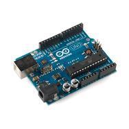
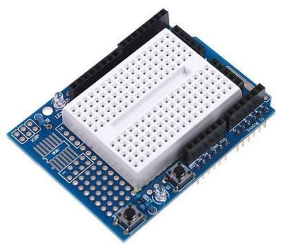
1 EGG 101L INTRODUCTION TO ENGINEERING EXPERIENCE LABORATORY 6: INTRODUCTION TO BREADBOARDS DEPARTMENT OF ELECTRICAL AND COMPUTER ENGINEERING UNIVERSITY OF NEVADA, LAS VEGAS GOAL: This section introduces breadboards and shows how they can be used in practical applications. OBJECTIVES: Understand breadboards and how they work Recreate the original LED blink exercise using a breadboard. OVERVIEW AND REQUIREMENTS: A breadboard is used to make up temporary circuits for experiments and preliminary stages of design ideas. Components are directly plugged into the board, so nothing is permanently in place and can be moved around as well as reused when necessary. The bread board has many strips of metal, usually copper, which run underneath the board connecting certain holes together and creating connective nodes. A node is a point in a circuit where two or more components are connected. The metal strips are typically laid out as shown below. DEPARTMENT OF ELECTRICAL AND COMPUTER ENGINEERING 1

, place them in the middle of the board so that half of the legs are on one side of the middle line and half are on the other side.")
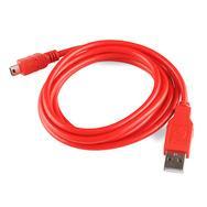
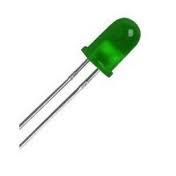
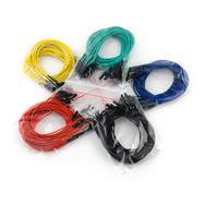
2 These strips connect the holes on the top of the board. This makes it easy to connect components together to build circuits. To use the bread board, the legs of components are placed in the holes. The long top and bottom row of holes are usually used for power supply connections. The rest of the circuit is built by placing components and connecting them together with jumper wires. Then when a path is formed by wires and components from the positive supply node to the negative supply node, we can turn on the power and current flows through the path and the circuit comes alive. For chips with many legs (ICs), place them in the middle of the board so that half of the legs are on one side of the middle line and half are on the other side. A circuit might look like the following. COMPONENTS: Arduino Uno USB A-B Cable Breadboard Shield LED Resistor Jumper Wire Host PC Installed Arduino Uno drivers and IDE DEPARTMENT OF ELECTRICAL AND COMPUTER ENGINEERING 2
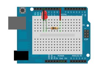
3 SCHEMATIC: Schematic 1 DEPARTMENT OF ELECTRICAL AND COMPUTER ENGINEERING 3


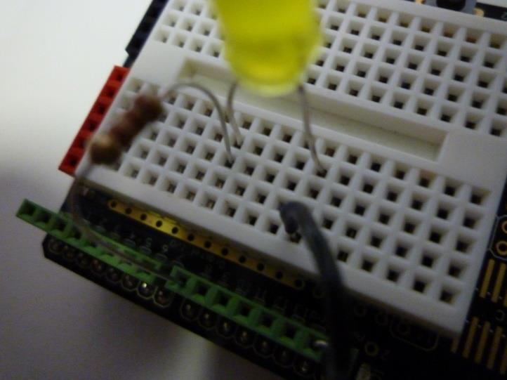
4 OPERATION: Connecting the LED 1. Attach the Breadboard Shield to the Arduino, making sure to properly align the pins. If you are using an R3 revision of the Arduino UNO, there will be 2 pins on each side that will have no corresponding pins on the shield. 2. Attach the Arduino UNO to the host PC with the use of the USB cable. Verify that the drivers have been properly installed. 3. Wire the circuit as shown in the schematic. Your final result should be something similar to the following snapshot. DEPARTMENT OF ELECTRICAL AND COMPUTER ENGINEERING 4


5 DEMO AND SCREENSHOTS: Using Danger Shield and Breadboard together: DEPARTMENT OF ELECTRICAL AND COMPUTER ENGINEERING 5
6 PRELAB: 1. List 2 ways of identifying which leg of a LED is the positive. 2. How do you set a pin as Input/Output? EXPERIMENTS: Experiment 1 1. Wire the Schematic1, connect LED to pin of your choice 2. Write your own code to blink the connected LED 3. Demonstrate the results to the TA Experiment 2 1. Extend the circuit and code from Experiment 1 the following way: a. Connect additional two LEDs, to the pins of your choice. Now you have three LEDs connected: LED1, LED2, and LED3. b. Modify the code, to have the following sequence: Light up LEDs in order (LED1=on,, LED2=on,, LED3=on) then turn off LEDS in order (LED3=off,, LED2=off,, LED1=off, ) Experiment 3 1. Use the circuit and code from Experiment Modify the code: a. Get the following sequence to work: LED1=on (LED2, LED3 are off) LED1=off (LED2, LED3 are off) LED2=on (LED1, LED3 are off) LED2=off (LED1, LED3 are off) LED3=on (LED1, LED2 are off) LED3=off (LED1, LED2 are off) repeat the sequence from the beginning Experiment 4 1. Use the code from Experiment Modify the code: a. Use slider1 to control the sequence speed. The same has to be used for the time where LED is on and off. As you have only ~half of the slider values available, multiply the value from the slider by 2. DEPARTMENT OF ELECTRICAL AND COMPUTER ENGINEERING 6
7 POSTLAB REPORT DELIVERIES Include the following elements in your postlab report: 1. Theory of operation a. Describe what the breadboard is, and why to use it. b. List 5 different components that could be placed in a breadboard. 2. Results of the experiments For each experiment, include: a. The code that you developed for the experiment. Each line that was added must be highlighted and commented with the explanation of what is its meaning. b. Brief explanation how the goal of the experiment was reached c. Screenshots of the serial monitor with the values, presenting the operation of your code 3. Answer the questions: a. What is typically found on breadboards that are missing from the breadboard shields used for this lab? b. What material is typically used to create connectivity between nodes on the breadboard? c. Why the resistor is used in series to connect LED? 4. Conclusions a. Write down your conclusions, things learned, problems encountered during the lab and how they were solved, etc. DEPARTMENT OF ELECTRICAL AND COMPUTER ENGINEERING 7
EGG 101L INTRODUCTION TO ENGINEERING EXPERIENCE
 EGG 101L INTRODUCTION TO ENGINEERING EXPERIENCE LABORATORY 7: IR SENSORS AND DISTANCE DEPARTMENT OF ELECTRICAL AND COMPUTER ENGINEERING UNIVERSITY OF NEVADA, LAS VEGAS GOAL: This section will introduce
Aim: To learn the resistor color codes and building a circuit on a BreadBoard. Equipment required: Resistances, millimeter, power supply
 Understanding the different components Aim: To learn the resistor color codes and building a circuit on a BreadBoard Equipment required: Resistances, millimeter, power supply Resistors are color coded
CPE 100L LOGIC DESIGN I
 CPE 100L LABORATORY 3: COMBINATIONAL CIRCUIT DESIGN FULL ADDER BY GRZEGORZ CHMAJ DEPARTMENT OF ELECTRICAL AND COMPUTER ENGINEERING UNIVERSITY OF NEVADA, LAS VEGAS GOALS: Develop the ability to write a
Objectives: Learn what an Arduino is and what it can do Learn what an LED is and how to use it Be able to wire and program an LED to blink
 Objectives: Learn what an Arduino is and what it can do Learn what an LED is and how to use it Be able to wire and program an LED to blink By the end of this session: You will know how to use an Arduino
EE 221 L CIRCUIT II. by Ming Zhu
 EE 221 L CIRCUIT II LABORATORY 6: OP AMP CIRCUITS by Ming Zhu DEPARTMENT OF ELECTRICAL AND COMPUTER ENGINEERING UNIVERSITY OF NEVADA, LAS VEGAS OBJECTIVE Learn to use Op Amp to implement simple linear
EE 320 L LABORATORY 9: MOSFET TRANSISTOR CHARACTERIZATIONS. by Ming Zhu UNIVERSITY OF NEVADA, LAS VEGAS 1. OBJECTIVE 2. COMPONENTS & EQUIPMENT
 EE 320 L ELECTRONICS I LABORATORY 9: MOSFET TRANSISTOR CHARACTERIZATIONS by Ming Zhu DEPARTMENT OF ELECTRICAL AND COMPUTER ENGINEERING UNIVERSITY OF NEVADA, LAS VEGAS 1. OBJECTIVE Get familiar with MOSFETs,
Lab #6: Op Amps, Part 1
 Fall 2013 EELE 250 Circuits, Devices, and Motors Lab #6: Op Amps, Part 1 Scope: Study basic Op-Amp circuits: voltage follower/buffer and the inverting configuration. Home preparation: Review Hambley chapter
EE 221 L CIRCUIT II. by Ming Zhu
 EE 22 L CIRCUIT II LABORATORY 9: RC CIRCUITS, FREQUENCY RESPONSE & FILTER DESIGNS by Ming Zhu DEPARTMENT OF ELECTRICAL AND COMPUTER ENGINEERING UNIVERSITY OF NEVADA, LAS VEGAS OBJECTIVE Enhance the knowledge
Lab 2.4 Arduinos, Resistors, and Circuits
 Lab 2.4 Arduinos, Resistors, and Circuits Objectives: Investigate resistors in series and parallel and Kirchoff s Law through hands-on learning Get experience using an Arduino hat you need: Arduino Kit:
Arduino Workshop 01. AD32600 Physical Computing Prof. Fabian Winkler Fall 2014
 AD32600 Physical Computing Prof. Fabian Winkler Fall 2014 Arduino Workshop 01 This workshop provides an introductory overview of the Arduino board, basic electronic components and closes with a few basic
Lab 2: Blinkie Lab. Objectives. Materials. Theory
 Lab 2: Blinkie Lab Objectives This lab introduces the Arduino Uno as students will need to use the Arduino to control their final robot. Students will build a basic circuit on their prototyping board and
EE 221 L CIRCUIT II. Learn to use LTspice to run circuit simulations for voltage, current, etc.
 EE 221 L CIRCUIT II LABORATORY 3: LTSPICE DEPARTMENT OF ELECTRICAL AND COMPUTER ENGINEERING UNIVERSITY OF NEVADA, LAS VEGAS OBJECTIVE Learn to use LTspice to run circuit simulations for voltage, current,
EE 221 L CIRCUIT II LABORATORY 4: AC CIRCUITS, CAPACITORS AND INDUCTORS UNIVERSITY OF NEVADA, LAS VEGAS OBJECTIVE COMPONENTS & EQUIPMENT BACKGROUND
 EE 221 L CIRCUIT II LABORATORY 4: AC CIRCUITS, CAPACITORS AND INDUCTORS DEPARTMENT OF ELECTRICAL AND COMPUTER ENGINEERING UNIVERSITY OF NEVADA, LAS VEGAS OBJECTIVE Compare the difference between DC and
The Art of Electrical Measurements
 The Art of Electrical Measurements Purpose: Introduce fundamental electrical test and measurement tools and the art of making electrical measurements. Equipment Required Prelab 1 Digital Multimeter 1 -
Industrial Electricity
 Industrial Electricity Name DUE //7 or //7 (Your next lab day) Prelab: efer to the tables on Page 5. Show work neatly and completely on separate paper for any entry labeled calculated. You do not need
EXPERIMENT 1 INTRODUCTION TO LABORATORY INSTRUMENTS
 EXPERIMENT 1 INTRODUCTION TO LABORATORY INSTRUMENTS 1.1 Objective: In this experiment, multimeters and some circuit components are introduced. You will learn the following things: i. Reading the color
Arduino Lesson 1. Blink. Created by Simon Monk
 Arduino Lesson 1. Blink Created by Simon Monk Guide Contents Guide Contents Overview Parts Part Qty The 'L' LED Loading the 'Blink' Example Saving a Copy of 'Blink' Uploading Blink to the Board How 'Blink'
EE320L Electronics I. Laboratory. Laboratory Exercise #3. Operational Amplifier Application Circuits. Angsuman Roy
 EE320L Electronics I Laboratory Laboratory Exercise #3 Operational Amplifier Application Circuits By Angsuman Roy Department of Electrical and Computer Engineering University of Nevada, Las Vegas Objective:
Build a Mintronics: MintDuino
 Build a Mintronics: MintDuino Author: Marc de Vinck Parts relevant to this project Mintronics: MintDuino (1) The MintDuino is perfect for anyone interested in learning (or teaching) the fundamentals of
Oregon State University Lab Session #1 (Week 3)
") Oregon State University Lab Session #1 (Week 3) ENGR 201 Electrical Fundamentals I Equipment and Resistance Winter 2016 EXPERIMENTAL LAB #1 INTRO TO EQUIPMENT & OHM S LAW This set of laboratory experiments
Oregon State University Lab Session #1 (Week 3) ENGR 201 Electrical Fundamentals I Equipment and Resistance Winter 2016 EXPERIMENTAL LAB #1 INTRO TO EQUIPMENT & OHM S LAW This set of laboratory experiments
THE BREADBOARD; DC POWER SUPPLY; RESISTANCE OF METERS; NODE VOLTAGES AND EQUIVALENT RESISTANCE; THÉVENIN EQUIVALENT CIRCUIT
 THE BREADBOARD; DC POWER SUPPLY; RESISTANCE OF METERS; NODE VOLTAGES AND EQUIVALENT RESISTANCE; THÉVENIN EQUIVALENT CIRCUIT YOUR NAME GTA S SIGNATURE LAB MEETING TIME Objectives: To correctly operate the
Arduino STEAM Academy Arduino STEM Academy Art without Engineering is dreaming. Engineering without Art is calculating. - Steven K.
 Arduino STEAM Academy Arduino STEM Academy Art without Engineering is dreaming. Engineering without Art is calculating. - Steven K. Roberts Page 1 See Appendix A, for Licensing Attribution information
Revision: Jan 29, E Main Suite D Pullman, WA (509) Voice and Fax
 Voice and Fax") Revision: Jan 29, 2011 215 E Main Suite D Pullman, WA 99163 (509) 334 6306 Voice and Fax Overview The purpose of this lab assignment is to provide users with an introduction to some of the equipment which
Revision: Jan 29, 2011 215 E Main Suite D Pullman, WA 99163 (509) 334 6306 Voice and Fax Overview The purpose of this lab assignment is to provide users with an introduction to some of the equipment which
EE-110 Introduction to Engineering & Laboratory Experience Saeid Rahimi, Ph.D. Labs Introduction to Arduino
 EE-110 Introduction to Engineering & Laboratory Experience Saeid Rahimi, Ph.D. Labs 10-11 Introduction to Arduino In this lab we will introduce the idea of using a microcontroller as a tool for controlling
Board Of Education, Revision C (28150)
") 599 Menlo Drive, Suite 00 Rocklin, California 95765, USA Office: (96) 624-8333 Fax: (96) 624-8003 General: info@parallax.com Technical: support@parallax.com Web Site: www.parallax.com Board Of Education,
599 Menlo Drive, Suite 00 Rocklin, California 95765, USA Office: (96) 624-8333 Fax: (96) 624-8003 General: info@parallax.com Technical: support@parallax.com Web Site: www.parallax.com Board Of Education,
Arduino Setup & Flexing the ExBow
 Arduino Setup & Flexing the ExBow What is Arduino? Before we begin, We must first download the Arduino and Ardublock software. For our Set-up we will be using Arduino. Arduino is an electronics platform.
INTRODUCTION. Figure 1 Three-terminal op amp symbol.
 Page 1/6 Revision 0 16-Jun-10 OBJECTIVES To reinforce the concepts behind operational amplifier analysis. Verification of operational amplifier theory and analysis. To successfully interpret and implement
For this exercise, you will need a partner, an Arduino kit (in the plastic tub), and a laptop with the Arduino programming environment.
, and a laptop with the Arduino programming environment.") Physics 222 Name: Exercise 6: Mr. Blinky This exercise is designed to help you wire a simple circuit based on the Arduino microprocessor, which is a particular brand of microprocessor that also includes
Physics 222 Name: Exercise 6: Mr. Blinky This exercise is designed to help you wire a simple circuit based on the Arduino microprocessor, which is a particular brand of microprocessor that also includes
Experiment 3 Ohm s Law
 Experiment 3 Ohm s Law The goals of Experiment 3 are: To identify resistors based upon their color code. To construct a two-resistor circuit using proper wiring techniques. To measure the DC voltages and
Experiment # 2 The Voting Machine
 Experiment # 2 The Voting Machine 1. Synopsis: In this lab we will build a simple logic circuit of a voting machine using TTL gates using integrated circuits that contain one or more gates packaged inside.
ZX Distance and Gesture Sensor Hookup Guide
 Page 1 of 13 ZX Distance and Gesture Sensor Hookup Guide Introduction The ZX Distance and Gesture Sensor is a collaboration product with XYZ Interactive. The very smart people at XYZ Interactive have created
PCB & Circuit Designing
 (Summer Training Program) 4 Weeks/30 Days PRESENTED BY RoboSpecies Technologies Pvt. Ltd. Office: W-53G, Sector-11, Noida-201301, U.P. Contact us: Email: stp@robospecies.com Website: www.robospecies.com
PCB & Circuit Designing (Summer Training Program) 6 Weeks/ 45 Days PRESENTED BY
 6 Weeks/ 45 Days PRESENTED BY") PCB & Circuit Designing (Summer Training Program) 6 Weeks/ 45 Days PRESENTED BY RoboSpecies Technologies Pvt. Ltd. Office: D-66, First Floor, Sector- 07, Noida, UP Contact us: Email: stp@robospecies.com
PCB & Circuit Designing (Summer Training Program) 6 Weeks/ 45 Days PRESENTED BY RoboSpecies Technologies Pvt. Ltd. Office: D-66, First Floor, Sector- 07, Noida, UP Contact us: Email: stp@robospecies.com
LAB II. INTRODUCTION TO LAB EQUIPMENT
 1. OBJECTIVE LAB II. INTRODUCTION TO LAB EQUIPMENT In this lab you will learn how to properly operate the oscilloscope Keysight DSOX1102A, the Keithley Source Measure Unit (SMU) 2430, the function generator
Precalculations Individual Portion Introductory Lab: Basic Operation of Common Laboratory Instruments
 Name: Date of lab: Section number: M E 345. Lab 1 Precalculations Individual Portion Introductory Lab: Basic Operation of Common Laboratory Instruments Precalculations Score (for instructor or TA use only):
CPSC 226 Lab Four Spring 2018
 CPSC 226 Lab Four Spring 2018 Directions. This lab is a quick introduction to programming your Arduino to do some basic internal operations and arithmetic, perform character IO, read analog voltages, drive
ArduCAM USB Camera Shield
 ArduCAM USB Camera Shield Application Note for MT9V034 Rev 1.0, June 2017 Table of Contents 1 Introduction... 2 2 Hardware Installation... 2 3 Run the Demo... 3 4 Tune the Sensor Registers... 4 4.1 Identify
Instructional Demos, In-Class Projects, & Hands-On Homework: Active Learning for Electrical Engineering using the Analog Discovery
 Instructional Demos, In-Class Projects, & Hands-On Homework: Active Learning for Electrical Engineering using the Analog Discovery by Dr. Gregory J. Mazzaro Dr. Ronald J. Hayne THE CITADEL, THE MILITARY
PSoC and Arduino Calculator
 EGR 322 Microcontrollers PSoC and Arduino Calculator Prepared for: Dr. Foist Christopher Parisi (390281) Ryan Canty (384185) College of Engineering California Baptist University 05/02/12 TABLE OF CONTENTS
EET140/3 ELECTRIC CIRCUIT I
 SCHOOL OF ELECTRICAL SYSTEM ENGINEERING UNIVERSITI MALAYSIA PERLIS EET140/3 ELECTRIC CIRCUIT I MODULE 1 PART I: INTRODUCTION TO BASIC LABORATORY EQUIPMENT PART II: OHM S LAW PART III: SERIES PARALEL CIRCUIT
Arduino: Sensors for Fun and Non Profit
 Arduino: Sensors for Fun and Non Profit Slides and Programs: http://pamplin.com/dms/ Nicholas Webb DMS: @NickWebb 1 Arduino: Sensors for Fun and Non Profit Slides and Programs: http://pamplin.com/dms/
Lab 6: Instrumentation Amplifier
 Lab 6: Instrumentation Amplifier INTRODUCTION: A fundamental building block for electrical measurements of biological signals is an instrumentation amplifier. In this lab, you will explore the operation
Workshop 9: First steps in electronics
 King s Maths School Robotics Club Workshop 9: First steps in electronics 1 Getting Started Make sure you have everything you need to complete this lab: Arduino for power supply breadboard black, red and
Lab 2 Electrical Safety, Breadboards, Using a DMM
 Lab 2 Electrical Safety, Breadboards, Using a DMM Objectives concepts 1. Safety hazards related to household electricity and electronics equipment 2. Differences between schematic and breadboard representations
PIR Motion Detector Experiment. In today s crime infested society, security systems have become a much more
 PIR Motion Detector Experiment I. Rationale In today s crime infested society, security systems have become a much more necessary and sought out addition to homes or stores. Motion detectors provide a
Adafruit 16-Channel Servo Driver with Arduino
 Adafruit 16-Channel Servo Driver with Arduino Created by Bill Earl Last updated on 2015-09-29 06:19:37 PM EDT Guide Contents Guide Contents Overview Assembly Install the Servo Headers Solder all pins Add
CPE 100L DIGITAL LOGIC DESIGN I DESIGN LABORATORY LABORATORY 1 LAB SAFETY QUIZ & LAB EQUIPMENT USE TUTORIAL UNIVERSITY OF NEVADA, LAS VEGAS GOALS:
 CPE 100L DESIGN LABORATORY LABORATORY 1 LAB SAFETY QUIZ & LAB EQUIPMENT USE TUTORIAL DEPARTMENT OF ELECTRICAL AND COMPUTER ENGINEERING UNIVERSITY OF NEVADA, LAS VEGAS GOALS: Introduce laboratory safety
Lab. I Electrical Measurements, Serial and Parallel Circuits
 Name (last, first) ECE 2100 ID Lab. I Electrical Measurements, Serial and Parallel Circuits Pre-Lab Important note: this is the pre-lab of Lab I. You can type in the answers, or print out and write in
Electric Circuit I Lab Manual Session # 2
 Electric Circuit I Lab Manual Session # 2 Name: ----------- Group: -------------- 1 Breadboard and Wiring Objective: The objective of this experiment is to be familiar with breadboard and connection made
TECH 3232 Fall 2010 Lab #1 Into To Digital Circuits. To review basic logic gates and digital logic circuit construction and testing.
 TECH 3232 Fall 2010 Lab #1 Into To Digital Circuits Name: Purpose: To review basic logic gates and digital logic circuit construction and testing. Introduction: The most common way to connect circuits
Training Schedule. Robotic System Design using Arduino Platform
 Training Schedule Robotic System Design using Arduino Platform Session - 1 Embedded System Design Basics : Scope : To introduce Embedded Systems hardware design fundamentals to students. Processor Selection
EE320L Electronics I. Laboratory. Laboratory Exercise #6. Current-Voltage Characteristics of Electronic Devices. Angsuman Roy
 EE320L Electronics I Laboratory Laboratory Exercise #6 Current-Voltage Characteristics of Electronic Devices By Angsuman Roy Department of Electrical and Computer Engineering University of Nevada, Las
Lab 5: Arduino Uno Microcontroller Innovation Fellows Program Bootcamp Prof. Steven S. Saliterman
 Lab 5: Arduino Uno Microcontroller Innovation Fellows Program Bootcamp Prof. Steven S. Saliterman Exercise 5-1: Familiarization with Lab Box Contents Objective: To review the items required for working
Revision: April 18, E Main Suite D Pullman, WA (509) Voice and Fax
 Voice and Fax") Revision: April 18, 2010 215 E Main Suite D Pullman, WA 99163 (509) 334 6306 Voice and Fax Overview In this lab assignment, we will use KVL and KCL to analyze some simple circuits. The circuits will be
Revision: April 18, 2010 215 E Main Suite D Pullman, WA 99163 (509) 334 6306 Voice and Fax Overview In this lab assignment, we will use KVL and KCL to analyze some simple circuits. The circuits will be
Weather Station Programmers Workshop October 2017
 Appui à la Recherche et au Développement Agricole (AREA) Weather Station Programmers Workshop October 2017 Prepared for Feed the Future Haiti Appui à la Recherche et au Développement Agricole (AREA) By
Adafruit 16-channel PWM/Servo Shield
 Adafruit 16-channel PWM/Servo Shield Created by lady ada Last updated on 2018-08-22 03:36:11 PM UTC Guide Contents Guide Contents Overview Assembly Shield Connections Pins Used Connecting other I2C devices
EE320L Electronics I. Laboratory. Laboratory Exercise #2. Basic Op-Amp Circuits. Angsuman Roy. Department of Electrical and Computer Engineering
 EE320L Electronics I Laboratory Laboratory Exercise #2 Basic Op-Amp Circuits By Angsuman Roy Department of Electrical and Computer Engineering University of Nevada, Las Vegas Objective: The purpose of
PCB & Circuit Designing (Summer Training Program 2014)
") (Summer Training Program 2014) PRESENTED BY In association with RoboSpecies Technologies Pvt. Ltd. Office: A-90, Lower Ground Floor, Sec- 4, Noida, UP Contact us: Email: stp@robospecies.com Website: www.robospecies.com
(Summer Training Program 2014) PRESENTED BY In association with RoboSpecies Technologies Pvt. Ltd. Office: A-90, Lower Ground Floor, Sec- 4, Noida, UP Contact us: Email: stp@robospecies.com Website: www.robospecies.com
Demon Pumpkin APPROXIMATE TIME (EXCLUDING PREPARATION WORK): 1 HOUR PREREQUISITES: PART LIST:
: 1 HOUR PREREQUISITES: PART LIST:") Demon Pumpkin This is a lab guide for creating your own simple animatronic pumpkin. This project encourages students and makers to innovate upon the base design to add their own personal touches. APPROXIMATE
Demon Pumpkin This is a lab guide for creating your own simple animatronic pumpkin. This project encourages students and makers to innovate upon the base design to add their own personal touches. APPROXIMATE
Sunday, November 4, The LadyUno Sound Unit
 The LadyUno Sound Unit Here s what we ll need for this project We start with our finished Lady Ada Wav Shield. 5V for LCD Serial Data for LCD GND for LCD 5V (coming from the BBB) is_lady_ada_busy PIN GND
APDS-9960 RGB and Gesture Sensor Hookup Guide
 Page 1 of 12 APDS-9960 RGB and Gesture Sensor Hookup Guide Introduction Touchless gestures are the new frontier in the world of human-machine interfaces. By swiping your hand over a sensor, you can control
EE-3306 HC6811 Lab #5. Oscilloscope Lab
 EE-3306 HC6811 Lab #5 Oscilloscope Lab Objectives: The purpose of this lab is to become familiar with the 68HC11 on chip Analog-to-Digital converter. In this lab, DC input voltages in 0V to +5V range are
INA169 Breakout Board Hookup Guide
 Page 1 of 10 INA169 Breakout Board Hookup Guide CONTRIBUTORS: SHAWNHYMEL Introduction Have a project where you want to measure the current draw? Need to carefully monitor low current through an LED? The
INSTALLATION MANUAL FOR 2U MODIFICATION KIT
 FOR 2U054-001 MODIFICATION KIT Kit for modification of ARC Type 385A Communication -Navigation System; (Extended COM Frequency Range: 118.000 to 136.975 MHz) Publication. No. 86M016 OCTOBER 1992 LIST OF
CPE 310L EMBEDDED SYSTEM DESIGN LABORATORY
 CPE 310L EMBEDDED SYSTEM DESIGN LABORATORY LABORATORY 1 LAB SAFETY & LAB EQUIPMENT USE TUTORIAL DEPARTMENT OF ELECTRICAL AND COMPUTER ENGINEERING UNIVERSITY OF NEVADA, LAS VEGAS GOALS: Introduce laboratory
Ardweeny 1.60" 0.54" Simple construction - only 7 parts plus pins & PCB! Ideal for breadboard applications
 Ardweeny tm Arduino -compatible Microcontroller Like to build your own breadboard-compatible Arduino? Get all the basic features of Arduino in a tidy, cost-effectve package! Build Time: 20mins Skill Level:
Breadboard Primer. Experience. Objective. No previous electronics experience is required.
 Breadboard Primer Experience No previous electronics experience is required. Figure 1: Breadboard drawing made using an open-source tool from fritzing.org Objective A solderless breadboard (or protoboard)
Practical Assignment 1: Arduino interface with Simulink
 !! Department of Electrical Engineering Indian Institute of Technology Dharwad EE 303: Control Systems Practical Assignment - 1 Adapted from Take Home Labs, Oklahoma State University Practical Assignment
GetTutorialized Workshops Brochure-2017
 GetTutorialized Workshops Brochure-2017 Internet of Things with Arduino Workshop course Content: 1. Introduction to Internet of Things 2. Introduction to Microcontrollers and Microprocessors 3. Microcontrollers
Experiment A3 Electronics I Procedure
 Experiment A3 Electronics I Procedure Deliverables: Checked lab notebook, Brief technical memo Overview Most of the transducers used in modern engineering applications are electronic, meaning they convert
LAB I. INTRODUCTION TO LAB EQUIPMENT
 1. OBJECTIVE LAB I. INTRODUCTION TO LAB EQUIPMENT In this lab you will learn how to properly operate the oscilloscope Agilent MSO6032A, the Keithley Source Measure Unit (SMU) 2430, the function generator
MAKEVMA502 BASIC DIY KIT WITH ATMEGA2560 FOR ARDUINO USER MANUAL
 BASIC DIY KIT WITH ATMEGA2560 FOR ARDUINO USER MANUAL USER MANUAL 1. Introduction To all residents of the European Union Important environmental information about this product This symbol on the device
smraza Getting Start Guide Contents Arduino IDE (Integrated Development Environment)... 1 Introduction... 1 Install the Arduino Software (IDE)...
... 1 Introduction... 1 Install the Arduino Software (IDE)...") Getting Start Guide Contents Arduino IDE (Integrated Development Environment)... 1 Introduction... 1 Install the Arduino Software (IDE)...1 Introduction... 1 Step 1: Get an Uno R3 and USB cable... 2 Step
Getting Start Guide Contents Arduino IDE (Integrated Development Environment)... 1 Introduction... 1 Install the Arduino Software (IDE)...1 Introduction... 1 Step 1: Get an Uno R3 and USB cable... 2 Step
MAE106 Laboratory Exercises Lab # 1 - Laboratory tools
 MAE106 Laboratory Exercises Lab # 1 - Laboratory tools University of California, Irvine Department of Mechanical and Aerospace Engineering Goals To learn how to use the oscilloscope, function generator,
ECE 220 Laboratory 3 Thevenin Equivalent Circuits, Constant Current Source, and Inverting Amplifier
 ECE 220 Laboratory 3 Thevenin Equivalent Circuits, Constant Current Source, and Inverting Amplifier Michael W. Marcellin The first portion of this document describes preparatory work to be completed in
UNIVERSITY OF NORTH CAROLINA AT CHARLOTTE Department of Electrical and Computer Engineering
 UNIVERSITY OF NORTH CAROLINA AT CHARLOTTE Department of Electrical and Computer Engineering EXPERIMENT 8 MOSFET AMPLIFIER CONFIGURATIONS AND INPUT/OUTPUT IMPEDANCE OBJECTIVES The purpose of this experiment
Laboratory experiments and reports
 LABORATORY INSTRUCTION MANUAL Page 1 of 8 Laboratory experiments and reports Summary This document describes how to carry out experimental exercises, and how to prepare the lab reports for the Electronic
EECS40 Lab Introduction to Lab: Guide
 Aschenbach, Konrad Muthuswamy, Bharathwaj EECS40 Lab Introduction to Lab: Guide Objective The student will use the following circuit elements and laboratory equipment to make basic circuit measurements:
Arduino An Introduction
 Arduino An Introduction Hardware and Programming Presented by Madu Suthanan, P. Eng., FEC. Volunteer, Former Chair (2013-14) PEO Scarborough Chapter 2 Arduino for Mechatronics 2017 This note is for those
How to Wire an Inverting Amplifier Circuit
 How to Wire an Inverting Amplifier Circuit Figure 1: Inverting Amplifier Schematic Introduction The purpose of this instruction set is to provide you with the ability to wire a simple inverting amplifier
ECE 2274 Lab 1 (Intro)
") ECE 2274 Lab 1 (Intro) Richard Dumene: Spring 2018 Revised: Richard Cooper: Spring 2018 Forward (DO NOT TURN IN) The purpose of this lab course is to familiarize you with high-end lab equipment, and train
ECE 2274 Lab 1 (Intro) Richard Dumene: Spring 2018 Revised: Richard Cooper: Spring 2018 Forward (DO NOT TURN IN) The purpose of this lab course is to familiarize you with high-end lab equipment, and train
ESE 350 Microcontroller Laboratory Lab 5: Sensor-Actuator Lab
 ESE 350 Microcontroller Laboratory Lab 5: Sensor-Actuator Lab The purpose of this lab is to learn about sensors and use the ADC module to digitize the sensor signals. You will use the digitized signals
EGR Laboratory 9 - Operational Amplifiers (Op Amps) Team Names
 Team Names") EG 1301 - Laboratory 9 - Operational Amplifiers (Op Amps) Team Names Objectives At the end of this lab, you will be able to: Construct and test inverting and non-inverting op amp circuits Compute calculated
EG 1301 - Laboratory 9 - Operational Amplifiers (Op Amps) Team Names Objectives At the end of this lab, you will be able to: Construct and test inverting and non-inverting op amp circuits Compute calculated
Product Manual QD1010-USB. Description. Contents. Material List. Setup. General Use. USB Cable Use. USB to RS485 Communications Converter
 Product Manual QD00-US US to Communications Converter Description The QD00-US is a US to converter used to allow asys Controls controllers to communicate with a PC. Material List QD00-US communication
Analog Discovery Arbitrary Function Generator for Windows 7 by Mr. David Fritz and Ms. Ellen Robertson
 Analog Discovery Arbitrary Function Generator for Windows 7 by Mr. David Fritz and Ms. Ellen Robertson Financial support to develop this tutorial was provided by the Bradley Department of Electrical and
ESE 150 Lab 04: The Discrete Fourier Transform (DFT)
") LAB 04 In this lab we will do the following: 1. Use Matlab to perform the Fourier Transform on sampled data in the time domain, converting it to the frequency domain 2. Add two sinewaves together of differing
LAB 04 In this lab we will do the following: 1. Use Matlab to perform the Fourier Transform on sampled data in the time domain, converting it to the frequency domain 2. Add two sinewaves together of differing
CECS LAB 4 Prototyping Series and Parallel Resistors
 NAME: POSSIBLE POINTS: 10 NAME: NAME: DIRECTIONS: We are going to step through the entire process from conceptual to a physical prototype for the following resistor circuit. STEP 1 - CALCULATIONS: Calculate
ENGR 1181 Lab 3: Circuits
 ENGR 1181 Lab 3: Circuits - - Lab Procedure - Report Guidelines 2 Overview of Circuits Lab: The Circuits Lab introduces basic concepts of electric circuits such as series and parallel circuit, used in
Non_Inverting_Voltage_Follower -- Overview
 Non_Inverting_Voltage_Follower -- Overview Non-Inverting, Unity-Gain Amplifier Objectives: After performing this lab exercise, learner will be able to: Understand and comprehend working of opamp Design
SV613 USB Interface Wireless Module SV613
 USB Interface Wireless Module SV613 1. Description SV613 is highly-integrated RF module, which adopts high performance Si4432 from Silicon Labs. It comes with USB Interface. SV613 has high sensitivity
PLAN DE FORMACIÓN EN LENGUAS EXTRANJERAS IN-57 Technology for ESO: Contents and Strategies
 Lesson Plan: Traffic light with Arduino using code, S4A and Ardublock Course 3rd ESO Technology, Programming and Robotic David Lobo Martínez David Lobo Martínez 1 1. TOPIC Arduino is an open source hardware
Laboratory 2 More Resistor Networks and Potentiometers.
 Laboratory More Resistor Networks and Potentiometers. Introduction Laboratory page of 5 This is a relatively short laboratory, because you will also be assembling your Micro-BLIP, a customized device based
Sept 13 Pre-lab due Sept 12; Lab memo due Sept 19 at the START of lab time, 1:10pm
 Sept 13 Pre-lab due Sept 12; Lab memo due Sept 19 at the START of lab time, 1:10pm EGR 220: Engineering Circuit Theory Lab 1: Introduction to Laboratory Equipment Pre-lab Read through the entire lab handout
EXPERIMENT 3 Circuit Construction and Operational Amplifier Circuits
 ELEC 2010 Lab Manual Experiment 3 PRE-LAB Page 1 of 8 EXPERIMENT 3 Circuit Construction and Operational Amplifier Circuits Introduction In this experiment you will learn how to build your own circuits
Lab 4 - Operational Amplifiers 1 Gain ReadMeFirst
 Lab 4 - Operational Amplifiers 1 Gain ReadMeFirst Lab Summary There are three basic configurations for operational amplifiers. If the amplifier is multiplying the amplitude of the signal, the multiplication
Never power this piano with anything other than a standard 9V battery!
 Welcome to the exciting world of Digital Electronics! Who is this kit intended for? This kit is intended for anyone from ages 13 and above and assumes no previous knowledge in the field of hobby electronics.
Understanding the Arduino to LabVIEW Interface
 E-122 Design II Understanding the Arduino to LabVIEW Interface Overview The Arduino microcontroller introduced in Design I will be used as a LabVIEW data acquisition (DAQ) device/controller for Experiments
LAB I. INTRODUCTION TO LAB EQUIPMENT
 LAB I. INTRODUCTION TO LAB EQUIPMENT 1. OBJECTIVE In this lab you will learn how to properly operate the basic bench equipment used for characterizing active devices: 1. Oscilloscope (Keysight DSOX 1102A),
Resistive Circuits. Lab 2: Resistive Circuits ELECTRICAL ENGINEERING 42/43/100 INTRODUCTION TO MICROELECTRONIC CIRCUITS
 NAME: NAME: SID: SID: STATION NUMBER: LAB SECTION: Resistive Circuits Pre-Lab: /46 Lab: /54 Total: /100 Lab 2: Resistive Circuits ELECTRICAL ENGINEERING 42/43/100 INTRODUCTION TO MICROELECTRONIC CIRCUITS
Lab 8. Stepper Motor Controller
 Lab 8. Stepper Motor Controller Overview of this Session In this laboratory, you will learn: To continue to use an oscilloscope How to use a Step Motor driver chip. Introduction This lab is focused around